

Ozito LFG-4100 Instruction Manual

WHAT’S IN THE BOX
CORDLESS
FINISHING
GRINDER
18V Li-ion
INSTRUCTION MANUAL
SPECIFICATIONS
Input: 18V
No Load Speed: 6000 / min
Disc Diameter: 100mm (4”)
Spindle Size: M10
Battery Power: 1.3Ah Li-ion
Charge Time: 3 - 5 Hours
Weight: 2 kg
ozito.com.au
Angle Grinder
18V Battery x 2
Pin Spanner
Allen Key
Charging Cradle
Charging Adaptor
LFG-4100
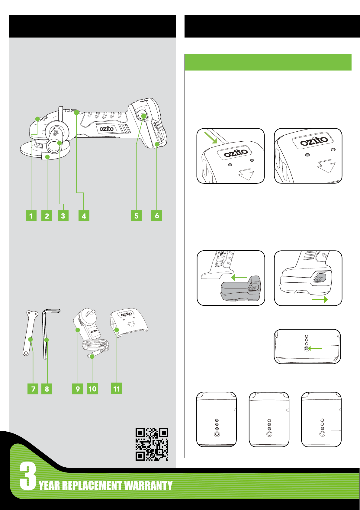
KNOW YOUR PRODUCT
SETUP & PREPARATION
CORDLESS FINISHING GRINDER
1. Spindle Lock
2. Adjustable Safety Guard
3. Side Handle
4 Lock On Slide Switch
5 Battery Release Button
6 18V Battery
1. BATTERY
This charger is recommended for use with a residual current
device with a rated residual current of 30mA or less.
Charging
1. Plug charging jack into
charging cradle. Both
lights will illuminate when
connected.
Note: Once fully charged, both the red and green lights will
illuminate.
Installing and Removing
Slide the battery into the
grinder base until it clicks into
place.
2. Slide cradle onto the battery.
Only the red light will be
illuminated when properly
connected and charging.
Hold down the battery release
buttons and slide the battery
out.
ACCESSORIES
7 Pin Wrench
8 Hex Key
9 Charging Adaptor
10 Charging Jack
11 Charging Cradle
Battery Indicator
1. Depress the battery
indicator button.
2. Observe which lights illuminate for a reading on your battery’s
charge.
ONLINE MANUAL
Scan this QR Code with your
mobile device to take you to
the online manual.
Charged
Low Charge
Flat

2. SIDE HANDLE & GUARD
Side Handle
The side handle can be tted on either side of your grinder. The
correct position will be determined by your preferred hand and the
operation being performed.
Attaching
1. Firmly attach the
side handle in the
desired position on
the grinder.
Removing
2. Remove the side
handle.
3. GRINDING DISC
Inspect the grinding disc before tment to ensure it is not cracked
or deformed. The grinding disc is suitable for grinding tasks only.
Only use grinding discs with a diameter of 100mm.
1. Depress and hold
spindle lock button.
2. Rotate spindle to locate
the lock position.
Safety Guard
The safety guard should be used at all times whilst operating the
nishing grinder.
Attaching
1. Loosen guard bolt, align tabs and
rotate guard to the required position.
Removing
3. Loosen guard bolt.
2. Tighten guard
bolt.
3. Use pin spanner to
loosen the outer ange.
5. Screw the outer ange onto the spindle.
Note: the ring on the ange must locate within the hole on the
grinding disc.
6. Depress and hold spindle
lock button. Firmly tighten
the outer ange with the
pin spanner.
4. Insert the disc with the
label facing up.
4. Align tabs on the guard with slots on the guard collar. Remove
guard.
7. Use the above operation in reverse to remove grinding disc.
CAUTION: REGULARLY CHECK THAT THE OUTER
FLANGE HAS NOT BECOME LOOSE DURING
OPERATION.
 Loading...