

Ozito JSW-6100 Instruction Manual

PENDULUM
JIGSAW
620W
INSTRUCTION MANUAL
SPECIFICATIONS
Input Power: 230-240V~50Hz
Motor: 620W
No Load Speed 800-3000spm
Stroke Depth: 20mm
Bevel: +/- 45°
Blade Fitment: Bayonet
Cutting Capacities: Timber 85mm
Mild Steel 8mm
Plastic 12mm
Weight: 2.1kg
JSW-6100
WHAT’S IN THE BOX
Jigsaw
Dust Extraction Adaptor
Parallel Guide
Splinter Guard
Blade
ozito.com.au
ONLINE MANUAL
Scan this QR Code with your
mobile device to take you to
the online manual.
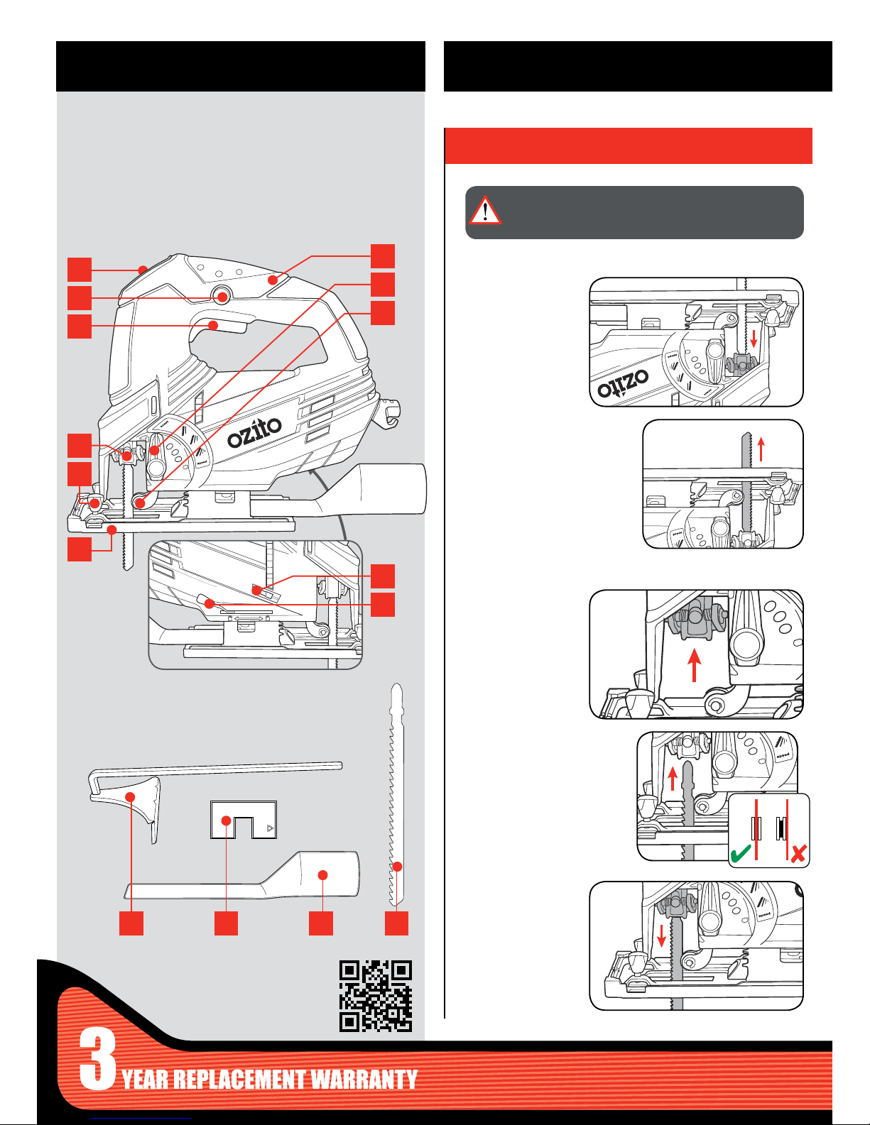
KNOW YOUR PRODUCT
1. CHANGING THE BLADE
Ensure the shoulder of
the blade sits right at
the bottom of the blade
holder.
12 Parallel Guide
13 Splinter Guard
14 Dust Extraction Adaptor
15 Blade
ACCESSORIES
1 Variable Speed Dial
2 Lock On Switch
3 On/Off Switch
4 Blade Lock
5 Guide Locking Screws
6 Adjustable Shoe
7 Soft Grip Handle
8 Pedulum Action Selector
9 Guide Roller
10 Dust Blower Switch
11 Shoe Locking Lever
PENDULUM JIGSAW
SETUP & PREPARATION
1
2
3
4
5
6
12 13 14 15
7
8
9
10
11
WARNING! ENSURE THE SAW IS SWITCHED OFF AND
DISCONNECTED FROM THE POWER SUPPLY BEFORE
PERFORMING ANY OF THE FOLLOWING ASSEMBLY.
Removing the Blade
Inserting the Blade
2 Raise the blade to remove.
2 Slide the blade into the lock
with the teeth facing forward
making sure the blade is in
the middle of the guide roller
groove.
1 Flip the saw upside
down and hold the
blade lock down.
1 Hold the blade lock
down.
3 Release the blade
lock and pull on the
blade to ensure it is
secured.
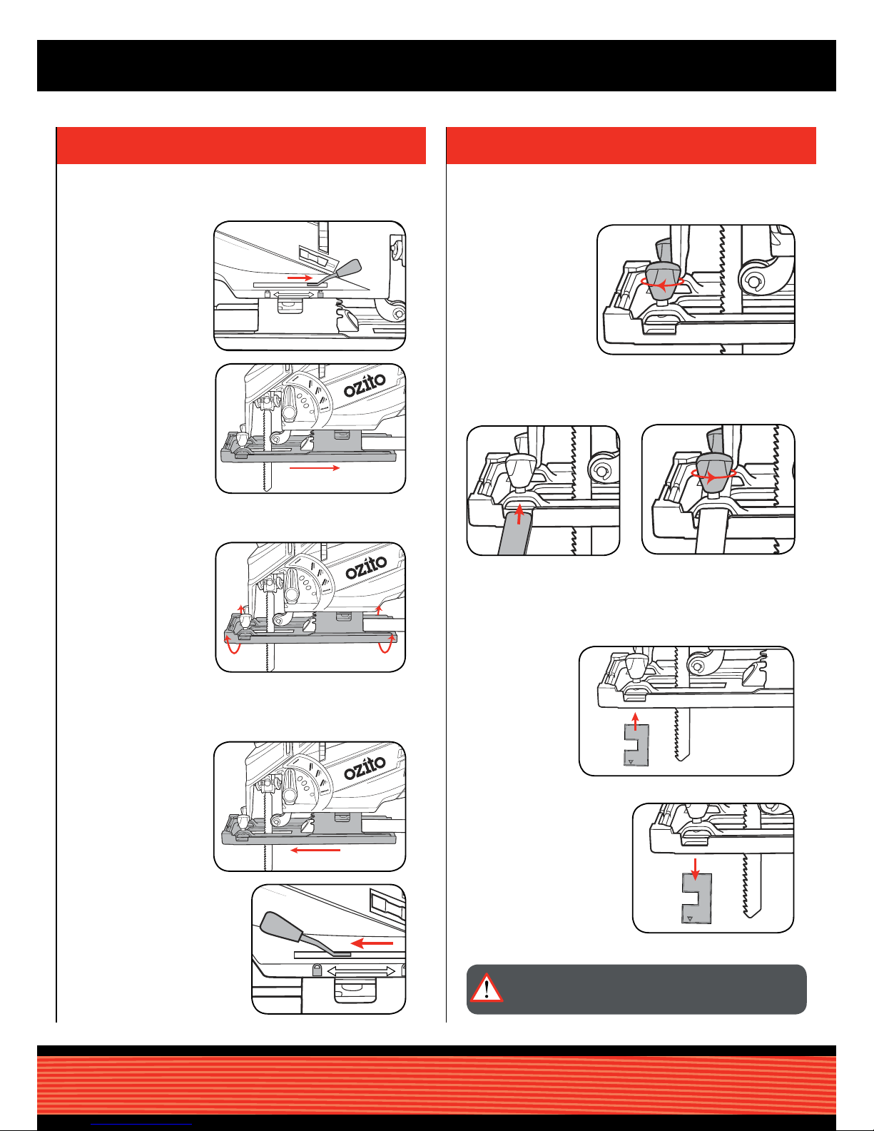
3. ATTACHING THE ACCESSORIES
The parallel guide assists in cutting in a line parallel to an edge.
The splinter guard ensures that the workpiece does not splinter and
crack while cutting.
2 Slide the parallel guide into
the slots under the locking
screws.
2 To Remove, pull splinter guard
away from the base.
1 Unscrew the guide
locking screws at the
front of the jigsaw.
1 Clip the splinter
guard into the
recesses in the
base of the jigsaw.
3 Tighten the guide locking
screws to secure position.
2. ADJUSTING SHOE ANGLE
The angle of the shoe can be adjusted to allow for bevel cuts between
0 and 45°.
WARNING! THE SPLINTER GUARD CAN ONLY BE USED
WHEN CUTTING AT A 900 ANGLE TO THE WORKPIECE.
Attaching the Parallel Guide
Using the Splinter Guard
2 Slide the shoe
backwards.
5 Secure in place by pulling the
shoe locking lever to the left.
1 Push the shoe
locking lever to the
right to unlock the
adjustable shoe.
4 Once the angle is
correct slide the
shoe foward for the
pin to make contact.
3 Tilt the shoe to the
desired angle using
the measurements.
 Loading...