


 Loading...
VDS Series PC Oscilloscopes
User Manual
WWW.OWON.COM.HK
Dec. 2013 edition V1.3
Copy Right in this Manual © Lilliput Company. All rights Reserved.
The Lilliput's products are under the protection of the patent rights in America and other countries, including ones which have already obtained the patent rights and those which are applying for. The information in this manual will replace all that in the materials published originally.
The information in this manual was correct at the time of printing. However, OWON will continue to improve products and reserves the rights to changes specification at any time without notice.
OWON is the registered trademark of the Lilliput Company.
Headquarter: Fujian Lilliput Optoelectronics Technology Co.,Ltd.: The mansion of optoelectronics, 19 Heming Road, Lantian industrial zone, Zhangzhou, Fujian, China
Tel:+86-596-2130430 |
Fax:+86-596-2109272 |
Web: www.owon.com.hk |
Mail: Business Consulting: info@owon.com.hk |
Sale service: service@owon.com.hk
Branch: Xiamen Lilliput Technology Co.,Ltd.: the 5th floor, B Area, Chuangxin Mansion, Software Park, ZhenZhuWan, Huandao RD, Xiamen, Fujian, China
Tel:+86-592-2575666 |
Fax:+86-592-2575669 |
General Warranty
Lilliput warrants that the product will be free from defects in materials and workmanship for a period of 3 years from the date of purchase of the product by the original purchaser from the Lilliput Company. And the warranty period of accessories such as probe is 12 month. This warranty only applies to the original purchaser and is not transferable to the third party. If the product proves defective during the warranty period, Lilliput either will repair the defective product without charge for parts and labor, or will provide a replacement in exchange for the defective product. Parts, modules and replacement products used by Lilliput for warranty work may be new or reconditioned to like new performance. All replaced parts, modules and products become the property of Lilliput.
In order to obtain service under this warranty, Customer must notify Lilliput of the defect before the expiration of the warranty period. Customer shall be responsible for packaging and shipping the defective product to the service center designated by Lilliput, and with a copy of customer proof of purchase.
This warranty shall not apply to any defect, failure or damage caused by improper use or improper or inadequate maintenance and care. Lilliput shall not be obligated to furnish service under this warranty a) to repair damage resulting from attempts by personnel other than Lilliput representatives to install, repair or service the product; b) to repair damage resulting from improper use or connection to incompatible equipment; c) to repair any damage or malfunction caused by the use of non-Lilliput supplies; or d) to service a product that has been modified or integrated with other products when the effect of such modification or integration increases the time or difficulty of servicing the product.
Please contact the nearest Lilliput's Sales and Service Offices for services or a complete copy of the warranty statement. For better after-sales service, please visit www.owon.com.hk and register the purchased product online.
Excepting the after-sales services provided in this summary or the applicable warranty statements, Lilliput will not offer any guarantee for maintenance definitely declared or hinted, including but not limited to the implied guarantee for marketability and special-purpose acceptability. Lilliput should not take any responsibilities for any indirect, special or consequent damages.
Table of Contents |
|
Table of Contents................................................................................................................................................................................................................................................................ |
4 |
VDS Oscilloscope Software Help..................................................................................................................................................................................................................................... |
1 |
VDS1022(I)/ VDS2052(I)................................................................................................................................................................................................................................................. |
1 |
VDS2062/VDS3102......................................................................................................................................................................................................................................................... |
2 |
VDS2064/VDS3104......................................................................................................................................................................................................................................................... |
2 |
I. PC Software USB Driver Install Guide ................................................................................................................................................................................................................. |
3 |
For Windows Vista or Windows 7..................................................................................................................................................................................................................... |
3 |
For Windows XP or Windows 2000.................................................................................................................................................................................................................. |
7 |
II. User Interface........................................................................................................................................................................................................................................................ |
10 |
III. Operations Instruction ........................................................................................................................................................................................................................................ |
11 |
1.How to Set the Probe Attenuation Coefficient........................................................................................................................................................................................... |
11 |
2.How to Set the Vertical System................................................................................................................................................................................................................... |
12 |
3.How to Set the Horizontal System .............................................................................................................................................................................................................. |
12 |
4.How to Set the Trigger System.................................................................................................................................................................................................................... |
13 |
5.How to Set the Channels.............................................................................................................................................................................................................................. |
15 |
6.How to Measure Automatically .................................................................................................................................................................................................................... |
15 |
7.How to Implement Sampling Setup ............................................................................................................................................................................................................ |
17 |
8.How to Measure with Cursors ..................................................................................................................................................................................................................... |
17 |
9.How to Set the Display System ................................................................................................................................................................................................................... |
19 |
10.Use Mathematical Manipulation Function................................................................................................................................................................................................ |
21 |
11.How to zoom the waveform........................................................................................................................................................................................................................ |
23 |
12.How to do Pass/Fail test............................................................................................................................................................................................................................. |
25 |
13.How to Record and Play a Waveform ...................................................................................................................................................................................................... |
26 |
14.How to Implement the Utility setting ......................................................................................................................................................................................................... |
27 |
15.How to Use Executive Buttons.................................................................................................................................................................................................................. |
28 |
16.Use LAN Port ............................................................................................................................................................................................................................................... |
29 |
IV. Technical Specifications ..................................................................................................................................................................................................................................... |
32 |
VDS Oscilloscope Software Help
Welcome to VDS Oscilloscope software.
The supplied accessories of the oscilloscope include a Quick Guide. The Quick Guide of the oscilloscope and the following helps are for your reference.
Minimum PC Requirements
Processor: Pentium(R) 4 2.4 GHz
Memory: 1GB
Disk space: 1GB minimum
Recommended PC Requirements
Processor: Pentium(R) Dual-Core 2.4 GHz
Memory: 2GB
Disk space: 1GB minimum
Other Requirements
Operating system: Windows XP(32-bit & 64-bit), Windows Vista(32-bit & 64-bit), Windows 7(32-bit & 64-bit)
Ports: USB2.0 USB1.1
Display Resolution: 1024 x 768
Ports Introduction
VDS1022(I)/ VDS2052(I)
1
2
 3
3
4
5
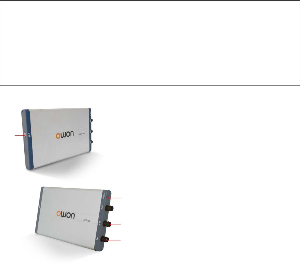
Figure Ports of the Oscilloscope(take VDS1022 for instance)
1.USB port: Supply power by PC USB or the adapter; communicate with PC
2.Probe Compensation: Measurement signal (5V/1KHz) output
3.MULTI port: EXT trigger input, trigger output or Pass/Fail output
4.Signal input of Channel 2
5.Signal input of Channel 1
Note: VDS1022(I) represents two types of machines, they are VDS1022I and VDS1022. VDS1022I contains isolation, while VDS1022 does not contain isolation. The same as VDS2052(I).
1

VDS2062/VDS3102
4
 5
5
6
7
Figure: Ports of the Oscilloscope (take VDS3102 for instance)
1.RS-232C Port (optional)
2.USB port: Supply power by PC USB or the adapter; communicate with PC
3.LAN port (optional): Network port which can be used to connect with PC
4.Probe Compensation: Measurement signal (3.3V/1KHz) output
5.EXT trigger input, trigger output or Pass/Fail output
6.Signal input of Channel 2
7.Signal input of Channel 1
VDS2064/VDS3104
Figure: Ports of the Oscilloscope (take VDS3104 for instance)
1.Probe Compensation: Measurement signal (3.3V/1KHz) output
2.MULTI port: EXT trigger input, trigger output or Pass/Fail output
3.LAN port (optional): Network port which can be used to connect with PC
4.USB port: Supply power by PC USB or the adapter; communicate with PC
5.Signal input of Channel 4
6.Signal input of Channel 3
7.Signal input of Channel 2
8.Signal input of Channel 1
Note: If you use LAN port to communicate with PC, the oscilloscope should be powered by the adapter.
2

I. PC Software USB Driver Install Guide
Use the supplied USB cable to connect the oscilloscope with a PC through their USB ports.
Note: If you use a USB cable that is not supplied by us, some problems such as connection error and signal disturbing might occur.
For Windows Vista or Windows 7
The Microsoft Windows Systems since Windows Vista or Windows 7, change a lot, which require a new installation guide of USB driver. Here it is.
During the whole installation, please assure that the device is running well and plugged into PC from USB.
Right click [Computer], you can find it on the desktop, or in [Start] menu.
in the pop up menu, click [Manage] and it will open a window named "Computer Management", as follow, in the left side click [Device Manager], it will show a devices tree in the middle, and then click the last one button "Scan for hardware changes" in tool bar as follow, and if the device is running well and plugged into PC, computer will detect an unknown device with a "!" icon.
Right click the unknown device icon, in the pop up menu click [Update Driver Software...],
In the open window, select [Browse my computer for driver software],
3
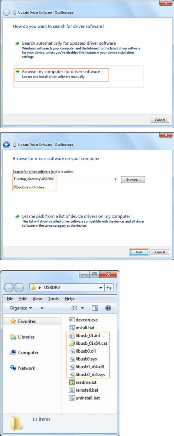
The next window, select a directory path for the driver software location, and click "Next",
Notice: the driver software location is a directory that is under the software setup folder named "USBDRV", and the contents inside are like these:
Or like this, than you should use the "USBDRV" directory to indicate the ".inf" file, and to the ".sys" or ".dll" file, you can indicate then in different directories like "x86", "ia64" or "amd64" depending on the CPU, but most of time just x86 and amd64 are enough.
4

OK, back to the driver installing, after last "Next" step, the system is installing driver software for you, as follow,
In the course,
It(for Windows XP x86&x64, Windows Vista x86&x64, Windows 7 x86) may open a window named "Windows Security" as below, and just select "Install this driver software anyway" to continue,
5
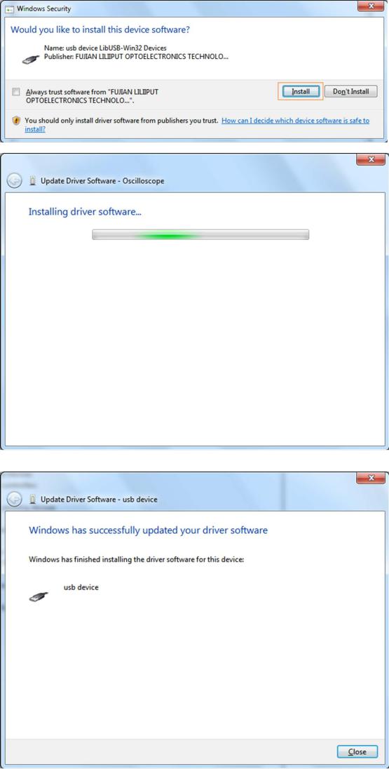
Or sometimes it(for Windows 7 x64) may open a window named "Windows Security" as below, and just click "Install" to continue,
And then continue installing,
And finish.
Now a successful installation window opens with information "Windows has successfully updated your driver software".
Close the window, have a look at the "Computer Management" window, you will find a device under [LibUSB-Win32 Devices], it should be like this:
6
Now the USB driver will work.
For Windows XP or Windows 2000
For Windows XP or Windows 2000
Notice: for both x86 and x64.
Plug into the running well device to open [Found New Hardware Wizard] dialog.
Or you can right click [My Computer] and select [Manage], in the left area of opened [Computer Management] select [Device Manager] , double click the item [USB Device] with "?" in the middle area to open the Wizard,
In the Wizard, select [No, not this time] ,
7
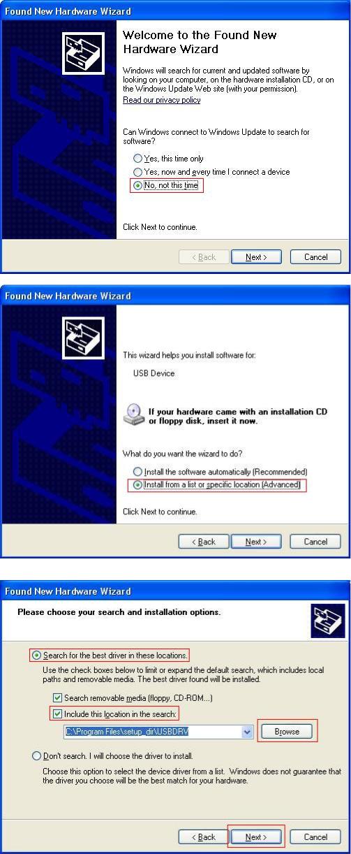
select [Install from a list or specific location(Advanced)] ,
select [Search for the best driver in these locations.] , then select [Include this location in the search] and indicate a directory location for USB driver which is named as "USBDRV" and under the directory where you installed the program at,
Then the installation is running,
8
Loading...