


PDS Series
Portable Mixed Signal Digital Storage Oscilloscope
User Manual
■PDS8102T
■PDS8202T
WWW.OWON.COM.CN

April 2010 edition
Copy Right in this Manual © Lilliput Company. All rights have been reserved.
The Lilliput’s products are under the protection of the patent rights in America and other countries,
including ones which have already obtained the patent rights and those which are applying for. The
information in this manual will replace all that in the materials published originally.
The information in this manual was correct at the time of printing. However,
Lilliput will continue to
improve products and reserves the rights to changes specification at any time without notice.
OWON is the registered trademark of the Lilliput Company.
Xiamen Lilliput Technology Co.,Ltd.: the 5th floor, B Area, Chuangxin Mansion, Software
Park,ZhenZhuWan, Huandao RD, Xiamen,Fujian,China
Fujian Lilliput Optoelectronics Technology Co.,Ltd.:The mansion of optoelectronics hengsan road,
Lantian industrial zone ,Zhangzhou,Fujian,China
Tel:+86-592-2575666
Fax:+86-592-2575669
Mail:sales@owon.com.cn

User Manual of OWON Color Mixed Signal Digital Storage Oscilloscope
General Warranty
The Lilliput warrants that the product will be free from defects in materials and
workmanship for a period of three years from the date of purchase of the product by the
original purchaser from the Lilliput company. And the warranty period of accessories such
as probe, battery, adapter is one year. This warranty only applies to the original purchaser
and is not transferable to the third party. If the product proves defective during the
warranty period, Lilliput either will repair the defective product without charge for parts
and labor, or will provide a replacement in exchange for the defective product. Parts,
modules and replacement products used by Lilliput for warranty work may be new or
reconditioned to like new performance.All replaced parts, modules and products become
the property of Lilliput.
In order to obtain service under this warranty, Customer must notify Lilliput of the defect
before the expiration of the warranty period. Customer shall be responsible for packaging
and shipping the defective product to the service center designated by Lilliput, and with a
copy of customer proof of purchase.
This warranty shall not apply to any defect, failure or damage caused by improper use or
improper or inadequate maintenance and care. Lilliput shall not be obligated to furnish
service under this warranty a) to repair damage resulting from attempts by personnel other
than Lilliput representatives to install, repair or service the product; b) to repair damage
resulting from improper use or connection to incompatible equipment; c) to repair any
damage or malfunction caused by the use of non-Lilliput supplies; or d) to service a
product that has been modified or integrated with other products when the effect of such
modification or integration increases the time or difficulty of servicing the product.
Please contact the nearest Lilliput’s Sales and Service Offices for services or a complete
copy of the warranty statement.
Excepting the after-sales services provided in this summary or the applicable warranty
statements, Lilliput will not offer any guarantee for maintenance definitely declared or hinted,
including but not limited to the implied guarantee for marketability and special-purpose
acceptability. Lilliput should not take any responsibilities for any indirect, special or consequent
damages.

User Manual of OWON Color Mixed Signal Digital Storage Oscilloscope
1
Table of Contents
1.General Safety Requirements........................................................................................... 3
2.Safety Terms and Symbols................................................................................................ 4
3.General Characteristics of the PDS Series Oscilloscope................................................6
4.Junior User Guidebook.................................................................................................... 7
Introduction to the Front Panel and the User's Interface of the PDS series Oscilloscope.... 8
Front panel ............................................................................................................................................... 8
Contrlo(key and knob) area...................................................................................................................... 9
User interface introduction....................................................................................................... 10
How to implement the General Inspection.............................................................................. 12
How to implement the Function Inspection ............................................................................ 12
How to Implement the Probe Compensation .......................................................................... 13
How to Set the Probe Attenuation Coefficient........................................................................ 14
How to Use the Probe Safely.....................................................................................................15
How to Implement Auto-calibration........................................................................................ 15
Introduction to the Vertical System......................................................................................... 16
Introduction to the Horizontal System .................................................................................... 17
Introduction to the Trigger System ......................................................................................... 18
5.Advanced User Guidebook............................................................................................. 19
How to Set the Vertical System ................................................................................................ 20
Implementation of Mathematical Manipulation Function .................................................... 25
Using FFT function ................................................................................................................................ 26
Application of VERTICAL POSITION and VOLTS/DIV Knobs........................................ 31
How to Set the Horizontal system ............................................................................................ 32
How to set trigger system.......................................................................................................... 36
Single trigger.......................................................................................................................................... 36
Alternate trigger .....................................................................................................................................41
How to Operate the Function Menu ........................................................................................ 46
How to Implement Sampling Setup .......................................................................................................46
How to Set the Display System.............................................................................................................. 48
How to Save and Recall a Wave Form................................................................................................... 53
How to Implement the Auxiliary System Function Setting.................................................................... 55
How to Implement the Automatic Measurement....................................................................................57
How to Implement the Cursor Measurement .........................................................................................59
How to use Autoscale............................................................................................................................. 64
How to Use Executive Buttons...............................................................................................................66

User Manual of OWON Color Mixed Signal Digital Storage Oscilloscope
2
6.Demonstration ................................................................................................................ 68
Example 1: Measurement of Simple Signals........................................................................... 68
Example 2: Gain of the Amplifier in the Metering Circuit ................................................... 69
Example 3: Capture the Single Signal ..................................................................................... 70
Example 4: Analyze the Details of a Signal............................................................................. 72
Example 5: Application of X-Y Function................................................................................ 73
Example 6: Video Signal Trigger............................................................................................. 74
7.F.A.Q ............................................................................................................................... 76
8. Technical Specifications................................................................................................77
General Technical Specifications ............................................................................................. 81
9. Appendix ........................................................................................................................ 82
Appendix A: Enclosure ............................................................................................................. 82
Appendix B: Maintenance, Cleaning and Repairing ............................................................. 82
Appendix C: Battery Using Guide ........................................................................................... 83

User Manual of OWON Color Mixed Signal Digital Storage Oscilloscope
3
1.General Safety Requirements
Before any operations, please read the following safety precautions to avoid any
possible bodily injury and prevent this product or any other products connected
from damage. In order to avoid any contingent danger, this product is only used
within the range specified.
Only the qualified technicians can implement the maintenance.
Prevent the Fire or Bodily Injury.
Connect the probe correctly. The grounding end of the probe corresponds to the
grounding phase. Please don't connect the grounding end to the positive phase.
Use the proper power line. Only use the power cord specially provided for this product
or that has been approved to be used in this user state.
Connect or Disconnect Correctly. When the probe or testing wire is connected to the
power lead, please do not connect and disconnect the probe or testing wire at random.
Product Grounded. This product is grounded through the power lead grounding
conductor. In order to prevent any electric shocking, the grounding conductor must be
connected to the ground. It requires guarantee that this product has been already grounded
correctly before any connection with its input or output terminal.
Pay attention to the nominal values of all terminals. In order to prevent any fire or
electric shock risks, please pay attention to all the nominal values and marks of this
product. Before implement any connections for this product, please read the user's manual
of this product to understand the information about the rated values further.
Do not make any operations without the instrument cover installed. If the cover or
panel has already been removed, please don't operate this product.
Use the proper fuse. Only the fuse complying with the specified type and nominal value
for this product can be used.
Avoid touching any exposed circuit. When the product is on power, please don't touch
the uncovered contacts and parts.
Please don't make any operations while there is an uncertain fault emerged. If
suspecting damage to this product, please contact the qualified maintenance personnel for
check.
Keep a good ventilation condition. Please consult the detailed installation instruction in
the user's manual so that this product can be erected correctly, keeping it under a good
ventilation condition.
Please do not make any operations in a moist environment.
Please do not make any operates in an explosive environment.
Keep the products surface clean and dry.
User Manual of OWON Color Mixed Signal Digital Storage Oscilloscope
4
2.Safety Terms and Symbols
Terms in this manual. The following terms may appear in this manual:
Warning. A warning statement indicates the conditions and actions which may
endanger the life safety.
Note. A note statement indicates the conditions and actions which may cause
damage to this product or other property.
Terms on the product. The following terms may appear on this product:
Danger: It indicates that there may be an immediate injury to you when you encounter
this mark.
Warning: It indicates that there may not be an immediate injury to you when you
encounter this mark.
Note: It indicates that there may be damage to this product or other property.
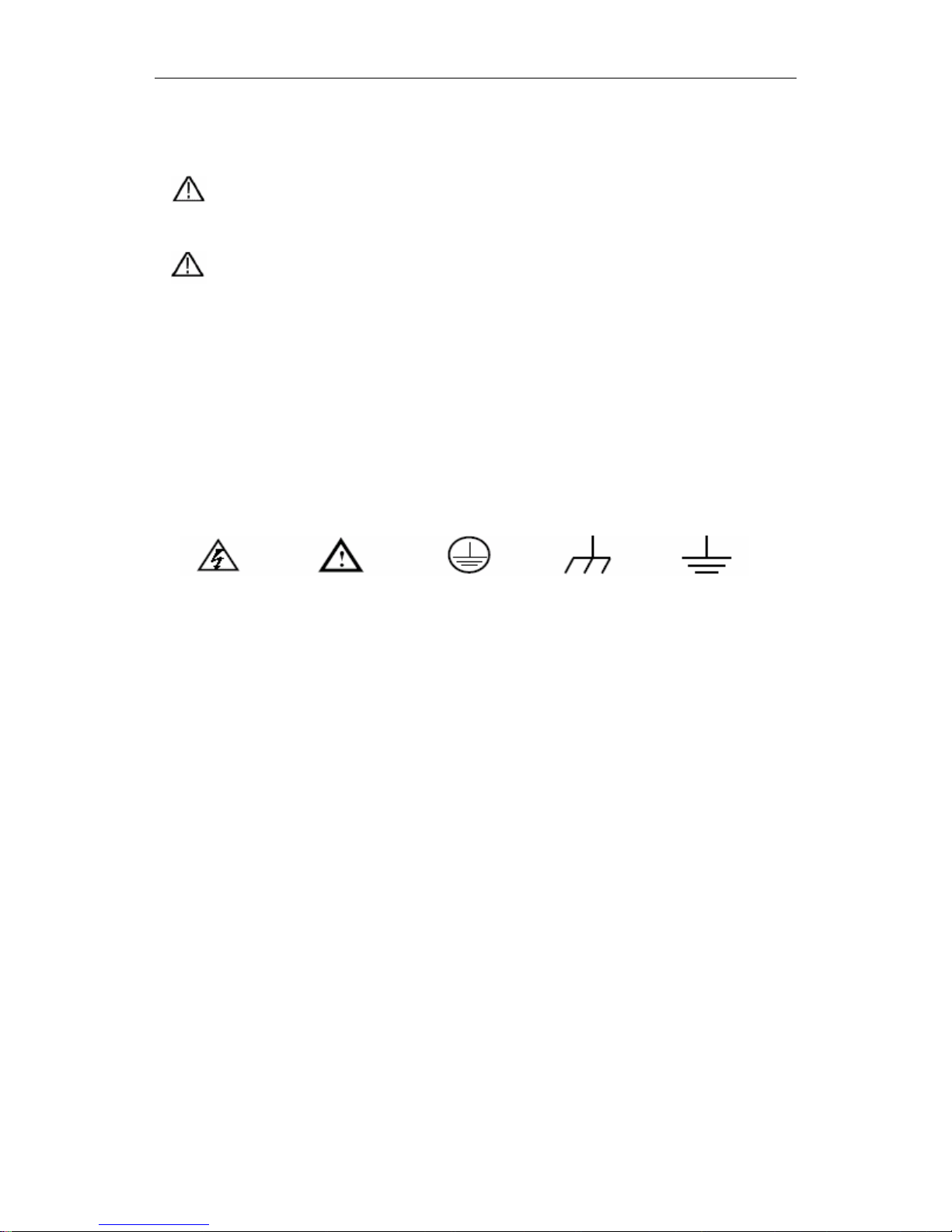
Symbols on the product. The following symbol may appear on the products:
High Voltage Please Consult the Manual. Protective Ground End Earth End on the Shell Grounding End for Measurement

User Manual of OWON Color Mixed Signal Digital Storage Oscilloscope
5
To avoid body damage and prevent product and connected equipment dam. This product
can only be used in the specified applications. Carefully read the following safety
information before using the test tool.
Warning:
When use BC(battery charge) as power supply, to avoid fire or electrical shock if
a test tool input is connected to more 42V peak (30Vrms) or on circuits of more than
4800VA:
z Only use accessory insulated voltage probes, test lead
z Before use, inspect oscilloscope probes, accessories for mechanical damage
and replace when damage.
z Remove all probes, test leads and accessories that are not in use.
z Remove computer data line
z Do not apply input voltages above the rating of the instrument Use caution
when using 1:1 test leads because the probe tip voltage will be directly
transmitted to the oscilloscope.
z Do not use exposed metal BNC or banana plug connectors
z Do not insert metal objects into connectors.

User Manual of OWON Color Mixed Signal Digital Storage Oscilloscope
6
3.General Characteristics of the PDS Series
Oscilloscope
Digital Storage Oscilloscope
z Model Bandwidth Sample Rate
PDS8102T 100MHz 1GS/s half channel*, 500MS/s each channel
PDS8202T 200MHz 2GS/s half channel*, 1G S/s each channel
z Dual channel, 2.5M points on each channel for the Record length;
z Reading-out with the cursor;
z Twenty automatic measurement functions;
z Autoscale function;
z Color liquid crystal display of high resolution and high contrast with adjustable
back light;
z Storage and call-out of waveforms;
z Automatic setting function provided capable of fast setting;
z Multiple-waveform calculation function;
z Built-in FFT function;
z Implementation of detecting the average and peak values of the waveform;
z Digital real-time oscilloscope;
z Edge, video,pulse,slope and alternate triggering function;
z RS232 or USB communication ports;
z Different continuous displaying time;
z Multiple Language User Interface.
. *Half channel is when only one channel is turned on.

User Manual of OWON Color Mixed Signal Digital Storage Oscilloscope
7
4.Junior User Guidebook
This chapter deals with the following topics mainly:
Digital Storage Oscilloscope
z Introduction to the front panel and the user’s interface of the PDS series
oscilloscope
z How to implement the general inspection
z How to implement the function inspection
z How to make a probe compensation
z How to set the probe attenuation coefficient
z How to use the probe safely
z How to implement an auto-calibration
z Introduction to the vertical system
z Introduction to the horizontal system
z Introduction to the trigger system

User Manual of OWON Color Mixed Signal Digital Storage Oscilloscope
8
Introduction to the Front Panel and the User's Interface of the
PDS series Oscilloscope
When you get a new-type oscilloscope, you should get acquainted with its front panel at
first and the PDS series mixed digital storage oscilloscope is no exception. This chapter
makes a simple description of the operation and function of the front panel of the PDS
series mixed oscilloscope, enabling you to be familiar with the use of the PDS series
mixed oscilloscope in the shortest time. The PDS series mixed oscilloscope offers a
simple front panel with distinct functions to users for their completing some basic
operations, in which the knobs and function pushbuttons are included. The knobs have the
functions similar to other oscilloscopes. The 5 buttons in the column on the right side of
the display screen are menu selection buttons (defined as F1 to F5 from top to bottom
respectively), through which, you can set the different options for the current menu. The
other pushbuttons are function buttons, through which, you can enter different function
menus or obtain a specific function application directly.
Front panel
Fig. 4-1 Front panel overview
1、 Power on/off
2、 Display area
3、 Control (key and knob) area
4、 U slot
5、 LA signal input
6、 DSO signal input
7、 Measurement signal output
User Manual of OWON Color Mixed Signal Digital Storage Oscilloscope
9
8、 Power and charging indication: Green light indicate AC supply and battery full
charged; yellow light indicate under charging.
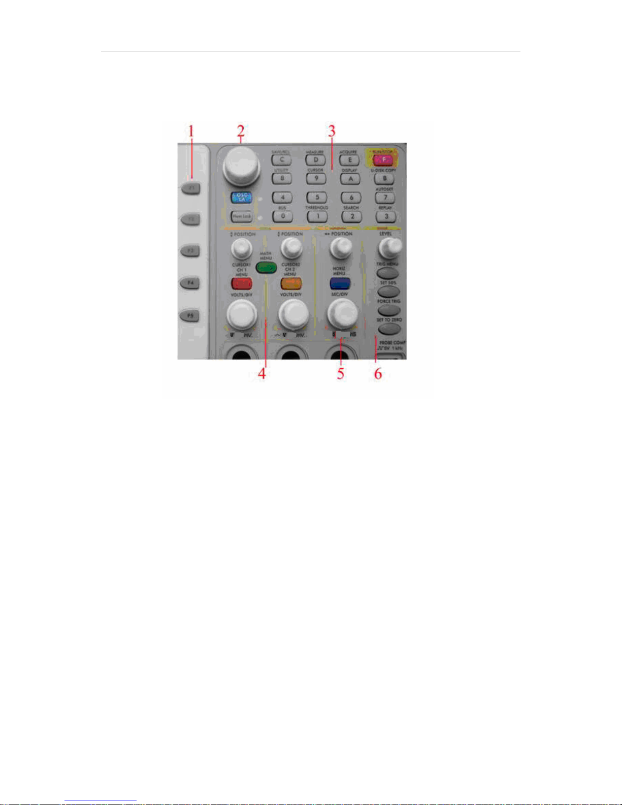
Contrlo(key and knob) area
Fig. 4-2 Keys Overview
1、1、Menu option setting: F1~F5
2、Switch
Switch includes two keys and one knob. The function for keys of "OSC/LA" and
"Info" is reserved.
For DSO “cursor” knob is idle.But it takes effect in magnifying or minificating the
waveform after FFT operation when the mode is FFT.
3、Function key area
For DSO 0~5 keys are idle and 6~F refer to different DSO function menu.
4、Vertical control area
It’s including 3 keys and 4 knobs.
For DSO: “CH1 menu” and “CH2 menu” correspond to setting menu in CH1 and CH2,
“Wave Math” key refer to math menu,the math menu consists of six kinds of
operations,including CH1-CH2、CH2-CH1、CH1+CH2 、CH1*CH2、CH1/CH2 and
FFT .Two “Vertical position” knob control the vertical position of CH1. CH2, and two
“Volts/Div” knob control voltage scale of CH1, CH2.
5、Horizontal control area with 2 knob and 1 key.
For DSO, “Horizontal position” knob control trigger position, “Volts/Div” control
time base, “Horizontal menu” key refer to horizontal system setting menu.
6、Trigger control area with 4 keys and 1 knob.
For DSO, “Trig adjust” knob is to adjust trigger voltage. Other four keys refer to
trigger system setting.
User Manual of OWON Color Mixed Signal Digital Storage Oscilloscope
10
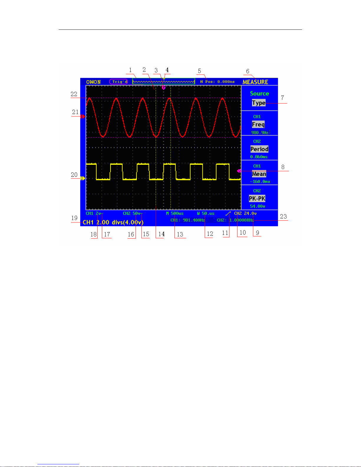
User interface introduction
Fig. 4-3 Illustrative Drawing of Display Interfaces
1. The Trigger State indicates the following information:
Auto: The oscilloscope is under the Automatic mode and is collecting the
waveform under the non-trigger state.
Trig' d: The oscilloscope has already detected a trigger signal and is collecting
the after-triggering information.
Ready: All pre-triggered data have been captured and the oscilloscope has been
already ready for accepting a trigger.
Scan: The oscilloscope captures and displays the waveform data continuously in
the scan mode.
Stop: The oscilloscope has already stopped the waveform data acquisition.
2. Waveform Viewing Area.
3. The purple pointer indicates the horizontal trigger position, which can be adjusted
by the horizontal position control knob.
4. The pointer indicates the trigger position in the internal memory.
5. This reading shows the time deviation between the horizontal trigger position and
the window centre line, which is regarded as 0 in the window center.

User Manual of OWON Color Mixed Signal Digital Storage Oscilloscope
11
6. It indicates the current function menu.
7. It indicates the operation options for the current function menu, which changes
with the function menus.
8. The purple pointer shows the trigger level position.
9. The reading shows the trigger level value.
10. The reading shows the trigger source.
11. It shows the selected trigger type:
Rising edge triggering
Falling edge triggering
Video line synchronous triggering
Video field synchronous triggering
12. The reading shows the window time base set value.
13. The reading shows the main time base set value.
14. The two yellow dotted lines indicate the size of the viewing expanded window.
15. The icon shows the coupling mode of the CH2 channel.
“—” indicates the direct current coupling
“ ~” indicates the AC coupling
“ ” indicates GND coupling.
16. The reading shows the vertical scale factor (the Voltage Division) of the CH2
channel.
17. The icon indicates the coupling mode of the CH1 channel:
The icon "–" indicates the direct current coupling
The icon "~" indicates the AC coupling
The icon " ” indicates GND coupling.
18. The reading indicates the vertical scale factor (the Voltage Division) of the CH1
channel.
19. The information shows the zero point positions of CH1 or CH2 channel.
20. The yellow pointer shows the grounding datum point (zero point position) of the
waveform of the CH2 channel. If the pointer is not displayed, it shows that this
channel is not opened.
21. The red pointer indicates the grounding datum point (zero point position) of the
waveform of the CH1 channel. If the pointer is not displayed, it shows that the
channel is not opened.

User Manual of OWON Color Mixed Signal Digital Storage Oscilloscope
12
22. The positions of two purple dotted line cursors measurements.
23. The reading shows the frequence of the two channels. It is a 6 digits
cymometer.Its measurement range of frequency is 2Hz to full bandwidth. when
the triggering mode is edge triggering,it is a one channel cymometer and it can
only measure the frequency of the tiggering channel. When the triggering mode is
alternating triggering,it is a two channel cymometer and it can measure the
frequency of two channels.
How to implement the General Inspection
After you get a new PDS series oscilloscope, it is recommended that you should make
a check on the instrument according to the following steps:
1. Check whether there is any damage caused by transportation.
If it is found that the packaging carton or the foamed plastic protection cushion has
suffered serious damage, do not throw it away first till the complete device and its
accessories succeed in the electrical and mechanical property tests.
2. Check the Accessories
The supplied accessories have been already described in the Appendix B
“Accessories” of this Manual. You can check whether there is any loss of accessories
with reference to this description. If it is found that there is any accessory lost or
damaged, please get in touch with the distributor of LILLIPUT responsible for this
service or the LILLIPUT’s local offices.
3. Check the Complete Instrument
If it is found that there is damage to the appearance of the instrument, or the
instrument can not work normally, or fails in the performance test, please get in touch
with the LILLIPUT’s distributor responsible for this business or the LILLIPUT’s
local offices. If there is damage to the instrument caused by the transportation, please
keep the package. With the transportation department or the LILLIPUT’s distributor
responsible for this business informed about it, a repairing or replacement of the
instrument will be arranged by the LILLIPUT.
How to implement the Function Inspection
Make a fast function check to verify the normal operation of the instrument, according
to the following steps:
1. Connect the Instrument to the Power and Push down the Power Switch Button.
The instrument carries out all self-check items and shows the prompt “Press any Key
Enter system”. Press the “8 (UTILITY)” button to get access to the “FUNCTION”
menu and push down F2 the menu selection button to call out the function “Recall
Factory”. The default attenuation coefficient set value of the probe in the menu is
User Manual of OWON Color Mixed Signal Digital Storage Oscilloscope
13
10X,
2. Set the Switch in the Oscilloscope Probe as 10X and Connect the Oscilloscope
with CH1 Channel.
Align the slot in the probe with the plug in the CH1 connector BNC, and then tighten
the probe with rotating it to the right side.
Connect the probe tip and the ground clamp to the connector of the probe
compensator.
3. Press the “7(AUTOSET)” Button.
The square wave of 1 KHz frequency and 5V peak-peak value will be displayed in
several seconds (see Fig. 4-4).
Fig.4-4 Auto set
Check CH2 by repeating Step 2 and Step 3.
How to Implement the Probe Compensation
When connect the probe with any input channel for the first time, make this
adjustment to match the probe with the input channel. The probe which is not
compensated or presents a compensation deviation will result in the measuring error
or mistake. For adjusting the probe compensation, please carry out the following
steps:
1. Set the attenuation coefficient of the probe in the menu as 10X and that of the
switch in the probe as 10X, and connect the oscilloscope probe with the CH1
channel. If a probe hook tip is used, ensure that it keeps in close touch with the
probe. Connect the probe tip with the signal connector of the probe compensator
User Manual of OWON Color Mixed Signal Digital Storage Oscilloscope
14
and connect the reference wire clamp with the ground wire connector of the
probe connector, and then press the button “7(AUTOSET)”.
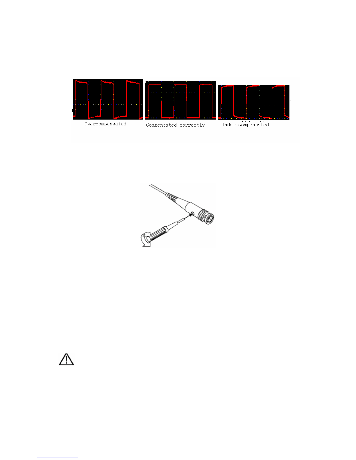
2. Check the displayed wave forms and regulate the probe till a correct
compensation is achieved (see Fig.4-5 and Fig.4-6).
Fig. 4-5 Displayed Wave Forms of the Probe Compensation
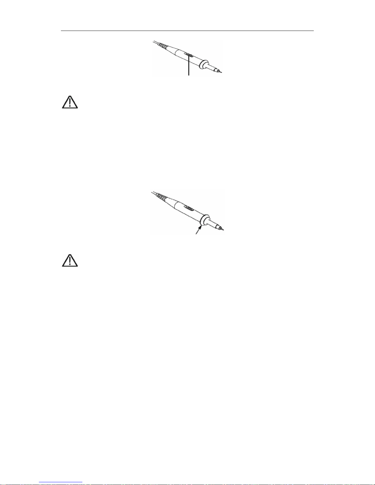
3. Repeat the steps mentioned if necessary.
Fig. 4-6 Adjust Probe
How to Set the Probe Attenuation Coefficient
The probe has several attenuation coefficients, which will influence the vertical scale
factor of the oscilloscope.
If it is required to change (check) the set value of the probe attenuation coefficient,
press the function menu button of the channels used, then push down the selection
button corresponding to the probe till the correct set value is shown.
This setting will be valid all the time before it is changed again.
Note: The attenuation coefficient of the probe in the menu is preset to 10X when
the oscilloscope is delivered from the factory.
Make sure that the set value of the attenuation switch in the probe is the same as the
menu selection of the probe in the oscilloscope.
The set values of the probe switch are 1X and 10X (see Fig. 4-7).
User Manual of OWON Color Mixed Signal Digital Storage Oscilloscope
15
Fig.4-7 Attenuation Switch
Note: When the attenuation switch is set to 1X, the probe will limit the bandwidth
of the oscilloscope in 5MHz. If it is needed to use the whole bandwidth of the
oscilloscope, the switch must be set to 10X.
How to Use the Probe Safely
The safety guard ring around the probe body protects your finger against the electric
shock, shown as Fig. 4-8.
Fig. 4-8 Finger Guard
Warning: In order to avoid suffering from the electric shock, please keep your
finger behind the safety guard ring of the probe body during the operation.
In order to protect you from suffering from the electric shock during your using the
probe, do not touch the metal part of the probe tip when the probe is connected to
the power supply.
Before making any measurements, please connect the probe to the instrument and connect the
ground terminal to the earth.
How to Implement Auto-calibration
The auto-calibration application can make the oscilloscope reach the optimum
condition rapidly to obtain the most accurate measurement value. You can carry out
this application program at any time, but when the range of variation of the ambient
temperature is up to or over 5 , this program must be executed.℃
For the performing of the self-calibration, all probes or wires should be disconnected
with the input connector first. Then, press the “8(UTILITY)” button to call out the
FUNCTION menu; push down the F3 menu selection button to choose the option
“ Do Self Cal”; finally, run the program after confirming that everything is ready now.

User Manual of OWON Color Mixed Signal Digital Storage Oscilloscope
16
Introduction to the Vertical System
Shown as Fig.4-9, there are a series of buttons and knobs in VERTICAL
CONTROLS. The following practices will gradually direct you to be familiar with
the using of the vertical setting.
Fig. 4-9 Vertical Control Zone
1. Use the button “VERTICAL POSITION” knob to show the signal in the center
of the waveform window. The “VERTICAL POSITION” knob functions the
regulating of the vertical display position of the signal. Thus, when the
“VERTICAL POSITION” knob is rotated, the pointer of the earth datum point
of the channel is directed to move up and down following the wave form.
Measuring Skill
If the channel is under the DC coupling mode, you can rapidly measure the DC
component of the signal through the observation of the difference between the wave
form and the signal ground.
If the channel is under the AC mode, the DC component will be removed by filtration.
This mode helps you display the AC component of the signal with a higher
sensitivity.
2. Change the Vertical Setting and Observe the Consequent State Information
Change.
With the information displayed in the status bar at the bottom of the waveform
window, you can determine any changes in the channel vertical scale factor.
z Rotate the vertical “VOLTS/DIV” knob and change the “Vertical Scale Factor
(Voltage Division)”, it can be found that the scale factor of the channel
corresponding to the status bar has been changed accordingly.
z Press buttons of “CH1 MENU”, “CH2 MENU” and “MATH MENU”, the
User Manual of OWON Color Mixed Signal Digital Storage Oscilloscope
17
operation menu, symbols, wave forms and scale factor status information of the
corresponding channel will be displayed in the screen.
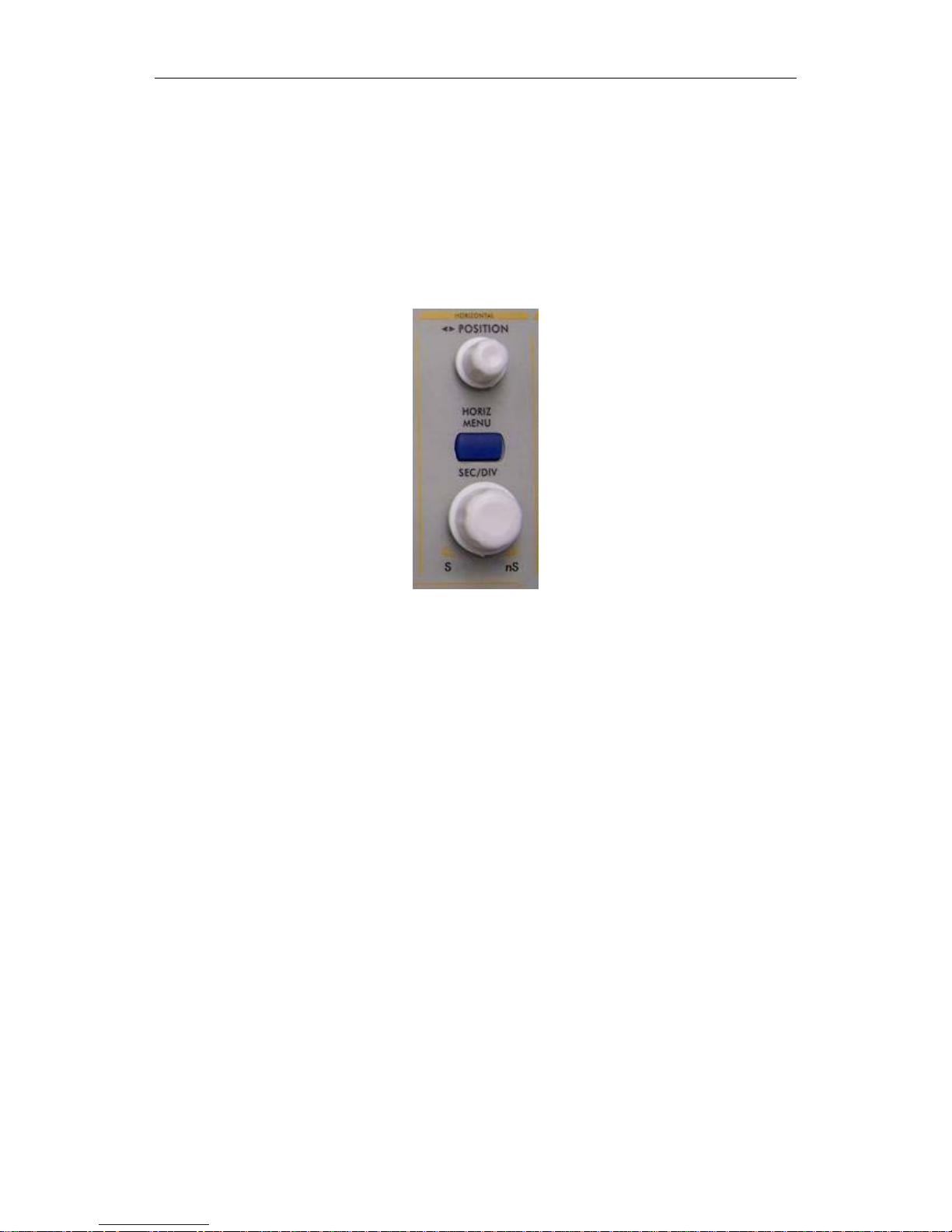
Introduction to the Horizontal System
Shown as Fig.4-10, there are a button and two knobs in the “HORIZONTAL
CONTROLS”. The following practices will gradually direct you to be familiar with
the setting of horizontal time base.
Fig. 4-10 Horizontal Control Zone
1. Use the horizontal “SEC/DIV” knob to change the horizontal time base setting
and observe the consequent status information change. Rotate the horizontal
“SEC/DIV” knob to change the horizontal time base, and it can be found that the
“Horizontal Time Base” display in the status bar changes accordingly. The
horizontal scanning speed steps from
2 ns up to 100s in the sequence of 1-2-5 -----PDS8102T;
1 ns up to 100s in the sequence of 1-2-5 -----PDS8202T.
2. Use the “HORIZONTAL POSITION” knob to adjust the horizontal position of
the signal in the waveform window. The “HORIZONTAL POSITION” knob is
used to control the triggering displacement of the signal or for other special
applications. If it is applied to triggering the displacement, it can be observed that
the wave form moves horizontally with the knob when you rotate the
“Horizontal Position” knob.
3. With the “HORIZONTAL MENU” button pushed down, you can set and
initiate the Window Expansion.
User Manual of OWON Color Mixed Signal Digital Storage Oscilloscope
18
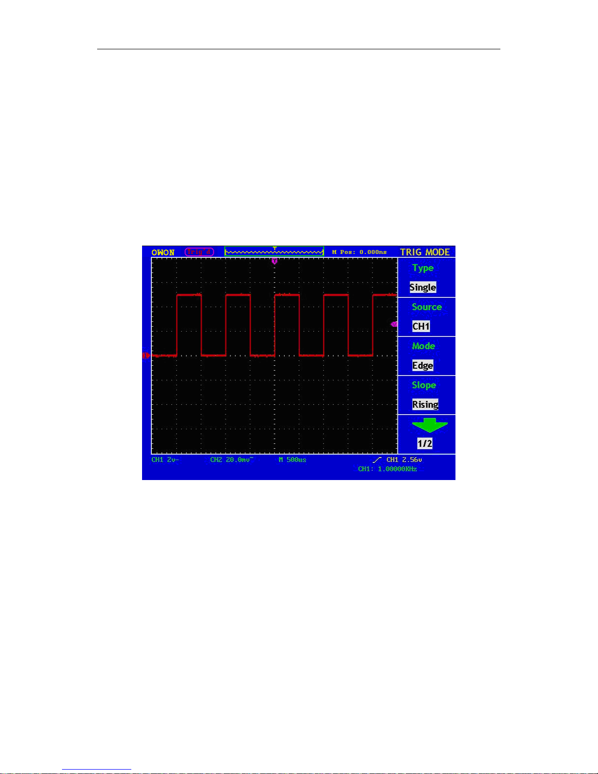
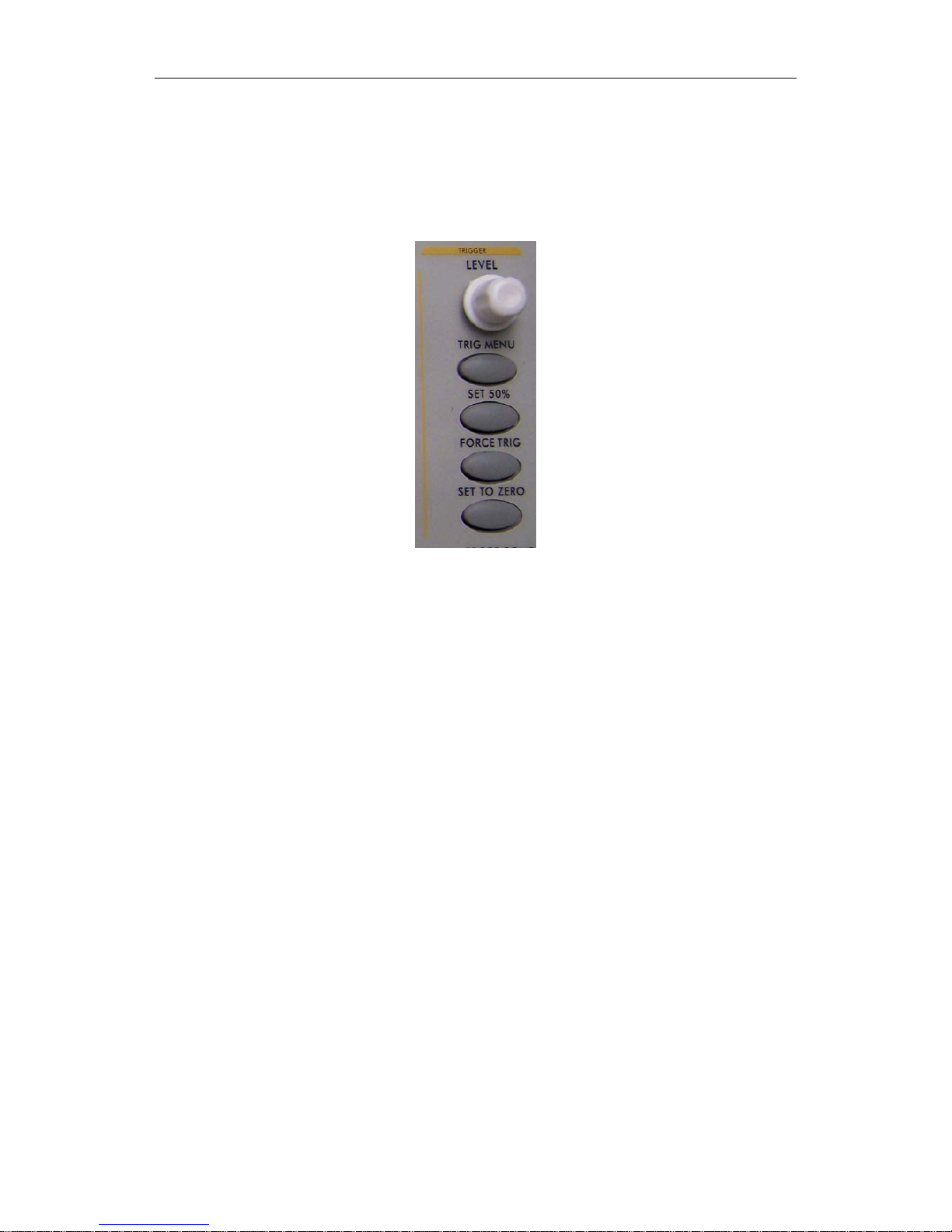
Introduction to the Trigger System
Shown as Fig.4-11, there are a knob and four buttons in the “TRIGGER
CONTROLS”. The following practices will direct you to be familiar with the setting
of the trigger system gradually.
Fig.4-11 Trigger Control Zone
1. Press the “TRIG MENU” button and call out the trigger menu. With the
operations of the 5 menu selection buttons, the trigger setting can be changed.
2. Use the “LEVEL” knob to change the trigger level setting.
With the rotation of the “LEVEL” knob, it can found that the trigger indicator in
the screen will move up and down with the rotation of the knob. With the
movement of the trigger indicator, it can be observed that the trigger level value
displayed in the screen changes.
3. Press the button “SET 50%” to set the trigger level as the vertical mid point
values of the amplitude of the trigger signal.
4. Press the “FORCE TRIG” button to force a trigger signal, which is mainly
applied to the “Normal" and "Single” trigger modes.
5. The “SET TO ZERO” button is used to reset the trigger horizontal position.

User Manual of OWON Color Mixed Signal Digital Storage Oscilloscope
19
5.Advanced User Guidebook
Up till now, you have already been familiar with the initial operations of the
functions of the function areas, buttons and knobs in the front panel of the PDS series
oscilloscope. Based the introduction of the previous Chapter, the user should have an
intimate knowledge of the determination of the change of the oscilloscope setting through
observing the status bar. If you have not been familiar with the above-mentioned
operations and methods yet, we advise you to read the section of “Chapter One Junior
Users' Guidebook”.
This chapter will deal with the following topics mainly:
z How to Set the Vertical System
z How to Set the Horizontal System
z How to Set the Trigger System
z How to Implement the Sampling Setup
z How to Set the Display System
z How to Save and Recall Wave Form
z How to Implement the Auxiliary System Function Setting
z How to Implement the Automatic Measurement
z How to Implement the Cursor Measurement
z How to Use Autoscale function
z How to Use Executive Buttons
z How to set Utility
It is recommended that you read this chapter carefully to get acquainted the various
measurement functions and other operation methods of the PDS series oscilloscope.
User Manual of OWON Color Mixed Signal Digital Storage Oscilloscope
20
How to Set the Vertical System
The VERTICAL CONTROLS includes three menu buttons such as CH1 MENU,
CH2 MENU and MATH MENU, and four knobs such as VERTICA POSITION,
VOLTS/DIV (one group for each of the two channels).
Setting of CH1 and CH2
Every channel has an independent vertical menu and each item is set respectively
based on the channel.
With the “CH1 MENU” or “CH2 MENU” menu button pushed down, the system
shows the operation menu of the corresponding channel (see Fig. 5-1).
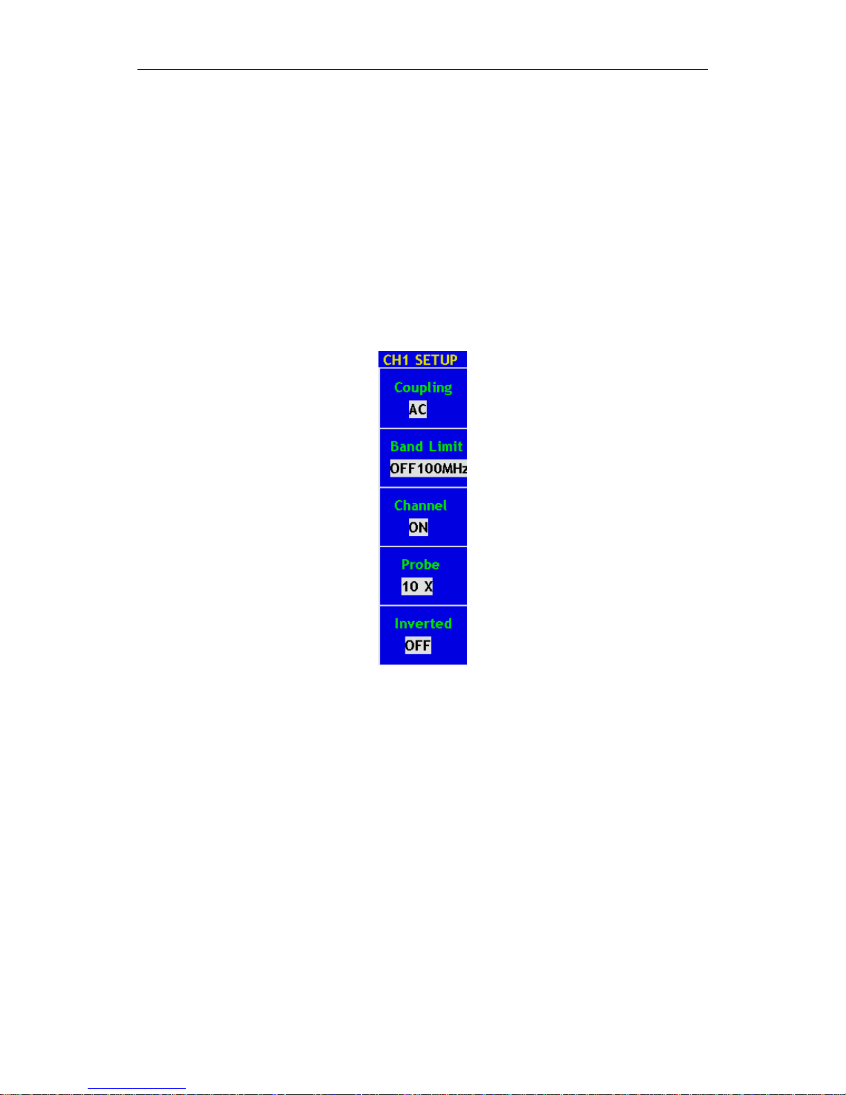
Fig. 5-1 Channel Setting Menu

User Manual of OWON Color Mixed Signal Digital Storage Oscilloscope
21
The description of the Channel Menu is shown as the following list:
Function Menu Setting Description
Coupling
AC
DC
GROUND
Block the DC component in the input signal.
Unblock the AC and DC components in the input
signal.
The Input signal is interrupted.
Band Limit
OFF 100MHz
ON 20MHz
Get full bandwidth.
Limits the channel bandwidth to 20MHz to reduce
display noise.
Channel
OFF
ON
Close the measurement channel.
Open the measuring channel.
Probe
1X
10X
100X
1000X
Choose one according to the probe attenuation factor to
make the vertical scale reading accurate.
Inverted
OFF
ON
The wave form is displayed normally.
Initiate the wave form inverted function.
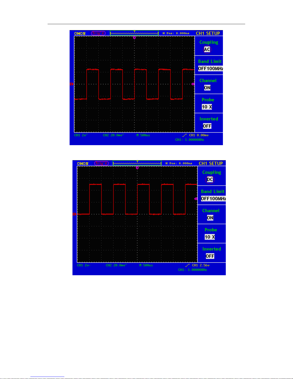
1. Setting Channel Coupling
Taking the Channel 1 for example, the measured signal is a square wave signal
containing the direct current bias. The operation steps are shown as below:
(1). Press the CH1 MENU button and call out the CH1 SETUP menu.
(2). Press the F1 menu selection button and select the Coupling item as “AC” to
set the channel coupling as ac mode, under which the direct current
component in the signal will be blocked.
Then, press the F1 menu selection button again and select the Coupling item as
“DC”, setting the channel coupling as dc mode, under which both dc and ac
components in the signal will be unblocked.
The wave forms are shown as Fig.5-2 and Fig.5-3.
User Manual of OWON Color Mixed Signal Digital Storage Oscilloscope
22
Fig. 5-2 AC Coupling Oscillogram
Fig. 5-3 DC Coupling Oscillogram
2. Setting the“Band Limit”
Taking the Channel 1 for example, the operation steps are shown as below:
(1). Press the CH1 MENU button and call out the CH1 SETUP menu.
(2). Press the F2 menu selection button and select the Band Limit as OFF
100MHz, with Channel 1 Band Limit switched off.
(3). Press F2 menu selection button again, select the Band Limit as ON
20MHz, with Channel 1 Band Limit is switched on.
User Manual of OWON Color Mixed Signal Digital Storage Oscilloscope
23
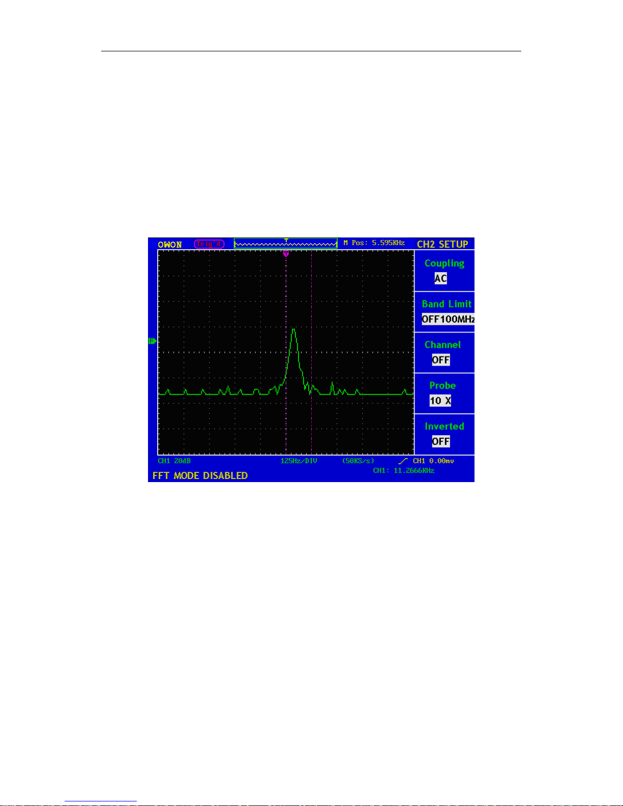
3. Setting the Channel “ON/OFF”
Taking the Channel 1 for example, the operation steps are shown as below:
(1). Press the CH1 MENU button and call out the CH1 SETUP menu.
(2). Press the F3 menu selection button and select the Channel as OFF, with
Channel 1 switched off.
(3). Press F3 menu selection button again, select the channel as ON, with
Channel 1 is switched on.
Note:In FFT mode, both CH1 and CH2 are not allowed to be ON when F3 is
pressed. See Fig.5-4.
Fig. 5-4 Channel CH1 is diable under FFT mode
4. Regulate the Attenuation Ratio of the Probe
In order to match the attenuation coefficient of the probe, it is required to adjust
the attenuation ration coefficient of the probe through the operating menu of the
Channel accordingly. If the attenuation coefficient of the probe is 1:1, that of the
oscilloscope input channel should also be set to 1X to avoid any errors presented
in the displayed scale factor information and the measured data.
Take the Channel 1 as an example, the attenuation coefficient of the probe is 10:1,
the operation steps is shown as follows:
(1). Press the CH1 MENU button, access CH1 SETUP menu.
(2). Press the F4 menu selection button and select 10X for the probe.
The Fig.24 illustrates the setting and the vertical scale factor when the probe of
the attenuation coefficient of 10:1.is used.
 Loading...