


 Loading...
HDS200 Dual Channel Series
Handheld Oscilloscope User Manual
HDS272 S
HDS242 S
HDS2102 S
For product support, visit:www.owon.com.hk/download

Oct 2021 edition V1.0.3
Copyright © LILLIPUT Company. All rights reserved.
The LILLIPUT's products are under the protection of the patent rights, including ones which have already obtained the patent rights and those which are applied for. The information in this manual will replace all materials published.
The information in this manual was correct at the time of printing. However, LILLIPUT will continue to improve products and reserves the rights to change specification at any time without notice.
is the registered trademark of the LILLIPUT Company.
Fujian LILLIPUT Optoelectronics Technology Co., Ltd.
No. 19, Heming Road
Lantian Industrial Zone, Zhangzhou 363005 P.R. China
Tel: +86-596-2130430 |
Fax: +86-596-2109272 |
Web: www.owon.com |
E-mail: info@owon.com.cn |
General Warranty
We warrants that the product will be free from defects in materials and workmanship for a period of 3 years from the date of purchase of the product by the original purchaser from the our Company. The warranty period for accessories such as probes, adapter is 12 months. This warranty only applies to the original purchaser and is not transferable to a third party.
If the product proves defective during the warranty period, we will either repair the defective product without charge for parts and labour, or will provide a replacement in exchange for the defective product. Parts, modules and replacement products used by our company for warranty work may be new or reconditioned like new. All replaced parts, modules and products become the property of our company.
In order to obtain service under this warranty, the customer must notify our company of the defect before the expiration of the warranty period. Customer shall be responsible for packaging and shipping the defective product to the designated service centre, a copy of the customers proof of purchase is also required.
This warranty shall not apply to any defect, failure or damage caused by improper use or improper or inadequate maintenance and care. We shall not be obligated to furnish service under this warranty a) to repair damage resulting from attempts by personnel other than our company representatives to install, repair or service the product; b) to repair damage resulting from improper use or connection to incompatible equipment; c) to repair any damage or malfunction caused by the use of not our supplies; or d) to service a product that has been modified or integrated with other products when the effect of such modification or integration increases the time or difficulty of servicing the product.
Please contact the nearest Sales and Service Offices for services or a complete copy of the warranty statement.
Excepting the after-sales services provided in this summary or the applicable warranty statements, we will not offer any guarantee for maintenance definitely declared or hinted, including but not limited to the implied guarantee for marketability and special-purpose acceptability. We should not take any responsibilities for any indirect, special or consequent damages

Table of Contents
1.SAFETY INFORMATION ···································3
2.HOW TO IMPLEMENT THE GENERAL INSPECTION 6
3.HOW TO USE THE OSCILLOSCOPE ··················7
The Structure of the Oscilloscope ·········································································7
Front Panel and Keys·························································································7
Side Panel·······································································································9
Introduction to the User Interface of the Oscilloscope ··············································10 Functional Check ····························································································11 Probe Compensation ·······················································································12 Probe Attenuation Coefficient Setting ···································································13 Safe Use of Probe ···························································································14 Vertical System·······························································································15 Horizontal System ···························································································16 Measuring System···························································································17
4.HOW TO USE THE MULTIMETER ·····················23
About This Chapter··························································································23
Instrument Interface·························································································24
5.HOW TO USE THE WAVEFORM GENERATOR
OPTIONAL ····················································26
Connect the output ···························································································26 Set the waveform······························································································26
Set the load ···································································································26 Output the sine waveform ·················································································27 Output the square waveform ··············································································28 Output the ramp waveform ················································································28 Output the pulse waveform················································································28 Output the Arbitrary waveform ············································································29
6.COMMUNICATION WITH PC ····························30
7.TROUBLESHOOTING ·····································31
8.TECHNICAL SPECIFICATIONS ························33
Oscilloscope ··································································································33
i

Multimeter ·····································································································35 Arbitrary Waveform Generator (Optional) ······························································36 General Technical Specifications ········································································38
9.APPENDIX ····················································39
Appendix A: List of Accessories ··········································································39 Appendix B: Maintenance and Cleaning ·······························································39
ii
1. Safety Information
(Before using this product, please read the safety information in advance)
Safety Terms
Terms in this manual (The following terms may appear in this manual):
Warning: Warning indicates conditions or practices that could result in injury or loss of life.
Caution: Caution indicates the conditions or practices that could result in damage to this product or other property.
Terms on the product. The following terms may appear on this product:
Danger: Indicates an immediate hazard or injury possibility.
Warning: Indicates a possible hazard or injury.
Caution: Indicates potential damage to the instrument or other property.
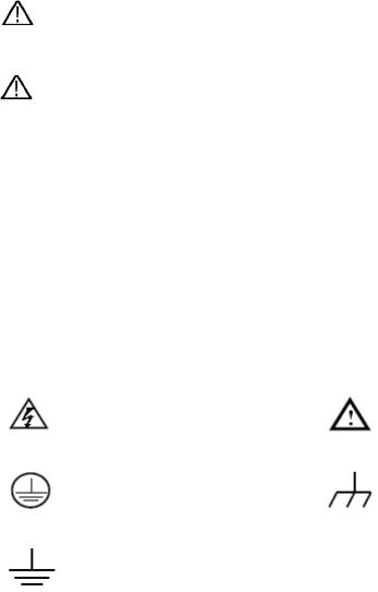
Safety Symbols
Symbols on the product. The following symbol may appear on the product:
Hazardous Voltage |
Refer to Manual |
Protective Earth Terminal |
Chassis Ground |
Test Ground
Safety Requirements
Please read the following safety precautions to avoid personal injury and prevent damage to this product or any other products connected to it. In order to avoid possible hazards, this product can only be used within the specified range.
3
 Warning:
To prevent electric shock or fire, use a suitable power adapter. Only power adapters that are dedicated to this product and approved for use in the country of use may be used.
 Warning:
The two channels of the oscilloscope are non-isolated channels. Note that the channel should use a common reference when measuring, and the ground wires of the two probes cannot be connected to two non-isolated places with different DC electrical levels, otherwise it may cause a short circuit due to the ground wire connection of the oscilloscope probe.
 Warning:
Note that the channel should use a common reference when measuring, otherwise it may cause a short circuit due to the ground wire connection of the oscilloscope probe.
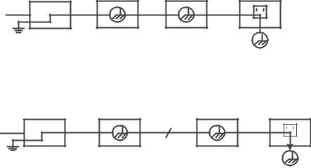
Schematic diagram of the internal ground wire connection of the oscilloscope:
Probe |
Oscilloscope |
AC Adapter |
Electrical Outlet |
Signal Input
Ground Clip
Schematic diagram of internal ground connection when oscilloscope is
connected with computer through the port:
Probe |
Oscilloscope |
PC |
Electrical Outlet |
Signal Input
USB Cable
Ground Clip
When the oscilloscope is AC powered by adapter or connected with AC
4
powered computer through the port, it is not allowed to measure the primary power supply of power grid.
 Warning:
If the input port of the oscilloscope is connected to a voltage with a peak value higher than 42V (30vrms) or a circuit with a peak value of more than 4800 VA, the following measures shall be taken to avoid electric shock or fire:
Only voltage probes, test wires and adapters with proper insulation attached to the oscilloscope or accessories suitable for oscilloscope instrument series products specified by our company shall be used.
Before use, check the multimeter test probe, oscilloscope probe and accessories for mechanical damage. If damage available, replace it.
Remove all unused multimeter test probes, oscilloscope probes and accessories (power adapter, USB, etc.).
Firstly, plug the power adapter into the AC socket, and then connect it to the oscilloscope.
When testing in a CAT II environment, do not connect a voltage higher than 400 V to any input port.
When testing in a CAT II environment, do not connect a voltage with a voltage difference of more than 400 V to the isolated input port.
Do not use an input voltage higher than the rated value of the instrument. Pay special attention when using 1:1 test wires, because the probe voltage will be directly transmitted to the oscilloscope.
Do not touch the bare metal BNC or banana plug.
Do not insert metal objects into the connector.
Use the oscilloscope only in the specified way.
The voltage rating mentioned in the "warning" information is the limited value of "working voltage". They represent V ac rms (50-60 Hz) in AC sine wave applications; and V dc in DC applications. CAT is the prefix, and II
5
refers to the level. Level II is the low voltage and high energy level, which refers to the local electrical level applicable to electrical appliances and portable equipment.
Only a qualified person should perform internal maintenance.
Check all Terminal Ratings. To avoid fire or shock hazard, check all ratings and markings on this product. Refer to the user manual for more information about ratings before connecting to the instrument.
Do not operate without covers. Do not operate the instrument with covers or panels removed.
Avoid exposed circuit. Be careful when working on exposed circuitry to avoid risk of electric shock or other injury.
Do not operate if any damage. If you suspect damage to the instrument, have it inspected by qualified service personnel before further use.
Do not operate in damp conditions.
Do not operate in an explosive atmosphere.
Keep product surfaces clean and dry.
Using the equipment not in accordance with the method specified by the manufacturer may damage the protection provided by the equipment.
2. How to Implement the General Inspection
After you get a new oscilloscope, it is recommended that you should make a check on the instrument according to the following steps:
1.Check whether there is any damage caused by transportation.
If it is found that the packaging carton or the foamed plastic protection cushion has suffered serious damage, do not throw it away first till the complete device and its accessories succeed in the electrical and mechanical property tests.
2.Check the Accessories
The supplied accessories have been already described in the "Appendix A: List of Accessories" of this Manual. You can check whether there is any loss of accessories with reference to this description. If it is found that there is any accessory lost or damaged, please get in touch with our distributor responsible for this service or our local offices.
3. Check the Complete Instrument
If it is found that there is damage to the appearance of the instrument, or the
6
instrument can not work normally, or fails in the performance test, please get in touch with our distributor responsible for this business or our local offices. If there is damage to the instrument caused by the transportation, please keep the package. With the transportation department or our distributor responsible for this business informed about it, a repairing or replacement of the instrument will be arranged by us.
3. How to Use the Oscilloscope
The Structure of the Oscilloscope
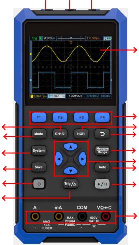
Front Panel and Keys
The front panel and keys of the oscilloscope are shown in Figure 4:
1 
 2
2
3
|
4 |
17 |
5 |
16 |
6 |
15 |
7 |
|
8 |
14 |
9 |
13 |
10 |
12 |
|
|
11 |
Figure 4: Front Panel of the Oscilloscope
7
Description:
1.CH1 and CH2 input connectors.
2.Waveform generator output connector (optional).
3.Display area.
4.The F1 - F4 keys are multi-function keys. In each menu mode, press the corresponding key to select the corresponding menu item.
5.After pressing the HOR key, through the key
 , you can change the horizontal time base setting, and observe the change of the state information caused by it; it can also be found that the horizontal time base display corresponding to the status bar has changed correspondingly; the horizontal displacement of the signal in the waveform window can be adjusted by pressing
 .
.
6.Return key. Press this key to return to the previous menu; when the menu is the first level, press the return key to close the menu.
7.Measurement menu key (oscilloscope) or range key (multimeter).
8.Zoom or move key:
Function of direction keys
 : used for the up and down movements of waveform, the time base changing, the voltage cursor movements and the trigger of electrical level change in the oscilloscope;
Function of direction keys
 : used for the left and right movements of waveform, the voltage position changing and the movements of time cursor in the oscilloscope.
9.Automatic setting key (oscilloscope) or automatic range key (multimeter).
10.Stop / run key (oscilloscope) or value hold key (multimeter) or turn on/off the signal output (waveform generator - optional).
11.Input end of the multimeter.
12.Trigger menu key (oscilloscope) or relative value key (multimeter).
13. : Power switch key.
14.Enter the save settings key.
8

15.Enter the system settings key.
16.Switch key for working state of oscilloscope and multimeter.
17.CH1 / CH2 - channel switch key.
Side Panel
 1
1
 2
2
 3
3
Description:
1.Probe compensation: 3.3V/1kHz square wave signal output
2.Charging or USB communication interface
3.Bracket
9

Introduction to the User Interface of the Oscilloscope
1 2 3 4 5 6 7 8
17 |
9 |
|
16 |
||
|
15 |
|
10 |
|
|
11 |
14 |
13 |
12 |
Figure 5: Oscilloscope Interface
Description:
1. The trigger status indicates the following information:
Auto: Automatic mode. The waveform is being collected without triggering.
Trig: A trigger has been detected and post trigger information is being collected.
Ready: All pre trigger data have been obtained and the oscilloscope is ready.
Scan: Scan mode. Continuously collect and display waveform data.
Stop: Stop collecting waveform data.
2.Run/stop.
3.Time base display.
4.The pointer indicates the trigger horizontal position.
5.The pointer indicates the trigger position within the current storage depth.
6.Indicating the value of the current trigger horizontal displacement, and displaying the position of the current waveform window in the memory.
7.It indicates that there is a USB disk connecting.
10
8.Battery power and external power supply indication.
9.Channel 1 waveform.
10.The pointer indicates the trigger electrical level position of the channel.
11.Channel 2 waveform.
12.The icon indicates trigger-related information, including trigger channel, coupling mode, trigger type and trigger electrical level. For details, please refer to P18 Trigger System.
13.The current sampling rate.
14.The channel information reading indicates the voltage position of the corresponding channel.
The icon indicates the coupling mode of the channel: "—" means DC coupling
" " means AC coupling
" " Means ground coupling
15.The pointer indicates the grounding reference point (zero position) of the waveform displayed in CH2 channel. If there is no pointer indicating the channel, it means that the channel is not open.
16.The pointer indicates the grounding reference point (zero position) of the waveform displayed in CH1 channel. If there is no pointer indicating the channel, it means that the channel is not open.
17.Waveform display area.
Functional Check
Making a quick functional check to verify that the instrument is working properly. Please proceed as follows:
1. Press the switch at the bottom left of the main unit  .
.
The internal relay will make a slight click. The instrument executes all self-check items, and the startup screen appears. Press the front panel key
System, the default probe menu attenuation coefficient setting value is 10X.
11
Loading...