


MX60 PV MPPT
(Maximum Power Point Tracking)
Charge Controller
Installation, Programming and User’s Manual
Warranty Summary
Dear OutBack Customer,
Thank you for your purchase of OutBack products. We make every effort to assure our power conversion products will give you long and reliable service for your renewable energy system.
As with any manufactured device, repairs might be needed due to damage, inappropriate use, or unintentional defect. Please note the following guidelines regarding warranty service of OutBack products:
•Any and all warranty repairs must conform to the terms of the warranty.
•All OutBack equipment must be installed according to their accompanying instructions and manuals with specifi ed over-current protection in order to maintain their warranties.
•The customer must return the component(s) to OutBack securely packaged, properly addressed, and shipping paid. We recommend insuring your package when shipping. Packages that are not securely packaged can sustain additional damage not covered by the warranty or can void
warranty repairs.
•There is no allowance or reimbursement for an installer’s or user’s labor or travel time required to disconnect, service, or reinstall the damaged component(s).
•OutBack will ship the repaired or replacement component(s) prepaid to addresses in the continental United States, where applicable. Shipments outside the U.S. will be sent freight collect.
•In the event of a product malfunction, OutBack cannot bear any responsibility for consequential losses, expenses, or damage to other components.
•Please read the full warranty at the end of this manual for more information.
2

The OutBack Power Systems MX60 PV MPPT Charge Controller is ETL listed to UL1741 (Inverters, Converters, Controllers, and Interconnection System Equipment for Use with Distributed Energy Resources). It is also in compliance with European Union standards EN 61000-6-1 and EN 61000-6-3 (see page 87).
About OutBack Power Systems
OutBack Power Systems is a leader in advanced energy conversion technology. Our products include true sine wave inverter/chargers, a maximum power point charge controller, system communication components, as well as breaker panels, breakers, accessories, and assembled systems.
Notice of Copyright
MX60 PV MPPT (Maximum Power Point Tracking) Charge Controller: Installation, Programming and User’s Manual
Copyright © 2007 All rights reserved.
Disclaimer
UNLESS SPECIFICALLY AGREED TO IN WRITING, OUTBACK POWER SYSTEMS:
(a)MAKES NO WARRANTY AS TO THE ACCURACY, SUFFICIENCY OR SUITABILITY OF ANY TECHNICAL OR OTHER INFORMATION PROVIDED IN ITS MANUALS OR OTHER DOCUMENTATION.
(b)ASSUMES NO RESPONSIBILITY OR LIABILITY FOR LOSS OR DAMAGE, WHETHER DIRECT,
INDIRECT, CONSEQUENTIAL OR INCIDENTAL, WHICH MIGHT ARISE OUT OF THE USE OF SUCH INFORMATION. THE USE OF ANY SUCH INFORMATION WILL BE ENTIRELY AT THE USER’S RISK.
Date and Revision
April, 2008 REV D Software REV 5.10 and 5.11
Contact Information
OutBack Power Systems 19009 62nd Ave. NE Arlington, WA 98223 Phone (360) 435-6030 Fax (360) 435-6019 www.outbackpower.com
3
TABLE OF CONTENTS |
|
INTRODUCTION........................................................................................................................................................................................ |
6 |
INSTALLATION GUIDELINES AND SAFETY INSTRUCTIONS............................................................................................. |
7 |
Standards and Requirements................................................................................................................................................. |
8 |
OPEN CIRCUIT VOLTAGE/WIRE AND DISCONNECT SIZING............................................................................................ |
9 |
BATTERY SYSTEM VOLTAGE.............................................................................................................................................................. |
14 |
POWERING UP ......................................................................................................................................................................................... |
15 |
STATUS SCREEN....................................................................................................................................................................................... |
18 |
PREPARING FOR RECHARGING ...................................................................................................................................................... |
19 |
ACCESSING THE MAIN MENU......................................................................................................................................................... |
20 |
CHARGER SETUP .................................................................................................................................................................................... |
21 |
AUX MODE................................................................................................................................................................................................. |
22 |
AUX MODE Path............................................................................................................................................................................ |
23 |
AUX Modes Described.............................................................................................................................................................. |
24 |
Programming the AUX MODES........................................................................................................................................... |
25 |
Manual...................................................................................................................................................................................... |
25 |
Vent Fan ................................................................................................................................................................................... |
25 |
PV Trigger ................................................................................................................................................................................ |
26 |
Float............................................................................................................................................................................................ |
27 |
Error Alarm.............................................................................................................................................................................. |
28 |
Diversion.................................................................................................................................................................................. |
28 |
Low Battery Disconnect................................................................................................................................................. |
31 |
Remote ..................................................................................................................................................................................... |
33 |
BACKLIGHT................................................................................................................................................................................................. |
34 |
EQ (Equalize)............................................................................................................................................................................................. |
34 |
MISC-MISCELLANEOUS...................................................................................................................................................................... |
37 |
WIDE/LMIT Battery Temperature Compensated Limits................................................................................................. |
38 |
ADVANCED................................................................................................................................................................................................ |
43 |
Snooze Mode.................................................................................................................................................................................. |
43 |
Park Mpp ........................................................................................................................................................................................... |
44 |
Mpp Range Limit % Voc........................................................................................................................................................... |
44 |
Sweep Interval ............................................................................................................................................................................... |
45 |
Vbatt Calibration........................................................................................................................................................................... |
45 |
Low Cutoff........................................................................................................................................................................................ |
46 |
MPPT Mode ..................................................................................................................................................................................... |
46 |
4
Absorb Time Limits ..................................................................................................................................................................... |
47 |
Wakeup Mode................................................................................................................................................................................ |
48 |
(DATA) LOGGING .................................................................................................................................................................................... |
49 |
Clearing Total and Daily Stats ............................................................................................................................................... |
50 |
LOG2.............................................................................................................................................................................................................. |
51 |
Secondary LOG2 Screen.......................................................................................................................................................... |
53 |
MICRO-HYDRO, WIND TURBINE, AND FUEL CELL APPLICATIONS............................................................................ |
54 |
ADVANCED MENU (Micro-Hydro) ............................................................................................................................................... |
56 |
MX60 ABBREVIATED MENU MAP.................................................................................................................................................. |
60 |
APPLICATION NOTES ........................................................................................................................................................................... |
61 |
FACTORY ASSISTANCE ........................................................................................................................................................................ |
62 |
SPECIFICATIONS...................................................................................................................................................................................... |
63 |
UNDERSTANDING THE VARIOUS OPERATIONAL MODES.............................................................................................. |
67 |
MATE-DISPLAYED MX60 STATUS MODE Screens ............................................................................................................... |
71 |
MATE-DISPLAYED MX60 STATUS METER Screens............................................................................................................... |
72 |
MATE-DISPLAYED MX60 STATUS SETP(SETPOINT) Screens......................................................................................... |
73 |
TROUBLESHOOTING GUIDE ............................................................................................................................................................ |
74 |
TYPICAL ARRAY SIZING GUIDE ...................................................................................................................................................... |
77 |
STANDARD vs. AUSTRALIAN DEFAULT SETTINGS............................................................................................................... |
78 |
WIRE DISTANCE CHART...................................................................................................................................................................... |
79 |
WIRE AND DISCONNECT SIZING .................................................................................................................................................. |
81 |
MULTI-STAGE BATTERY CHARGING............................................................................................................................................. |
82 |
BATTERY TEMPERATURE COMPENSATED VOLTAGE SET POINT................................................................................. |
84 |
SUGGESTED BATTERY CHARGER SET POINTS ...................................................................................................................... |
85 |
OWNER’S SYSTEM INFORMATION ............................................................................................................................................... |
86 |
EU DECLARATION OF CONFORMITY........................................................................................................................................ |
87 |
WARRANTY INFORMATION.............................................................................................................................................................. |
88 |
PRODUCT REGISTRATION................................................................................................................................................................. |
90 |
5
SCOPE
The manual provides safety guidelines and installation information for the MX60 PV MPPT Charge Controller. It does not provide information about specifi c brands of solar panels and supplies limited information on batteries. Contact the supplier or manufacturer of the solar panels or batteries for further information.
INTRODUCTION
MX60 PV MPPT (Maximum Power Point Tracking) Charge Controller
The OutBack MX60 PV MPPT Charge Controller offers an efficient, safe, multi-stage recharging process that prolongs battery life and assures peak performance from a solar array. This component allows customized battery recharging. The MX60 features include:
•60 amps maximum continuous output current
•Engineered to work with 12, 24, 36, 48, and 60 VDC battery voltages
•Backlit LCD display screen with 80 characters (4 lines, 20 characters per line)
•Last 64 days of operational data are logged for review
•Voltage step-down capability allowing a higher PV array voltage confi guration
•Manual and auto-equalize cycles
The following are the maximum recommended wattage for the most common solar arrays under Standard Test Conditions (1000 watts per square meter of solar panel at 25° C or 77° F):
•12 VDC battery systems—up to 800 watts of solar panels
•24 VDC battery systems—up to 1600 watts of solar panels
•48 VDC battery systems—up to 3200 watts of solar panels
The MX60 also features Maximum Power Point Tracking (MPPT), which seeks out the maximum power available from a solar array and uses it to recharge the batteries. Without this feature, the solar array does not operate at the ideal operating voltage and can only recharge at the level of the battery voltage itself. The MX60 “sweeps” the array’s operating voltage at user-determined sweep intervals to track the Maximum Power Point (MPP) of the PV array.
This manual covers the wiring, installation, and use of the MX60, including explanations of all the Menus displayed on the LCD screen. The MX60 is designed to seamlessly integrate with other OutBack components and can be remotely monitored (up to 1000 feet) by the optional OutBack Power Systems MATE display.
6

INSTALLATION GUIDELINES AND IMPORTANT SAFETY INSTRUCTIONS
SAVE THESE INSTRUCTIONS
This product is intended to be installed as part of a permanently grounded electrical system as shown in the system confi guration sections of this manual with the following important restrictions:
•The negative battery conductor should be bonded to the grounding system at only one point in the system. If a GFP (Ground Fault Protector) is present, the battery negative and ground are not bonded.
•With the exception of certain telcom applications, the MX60 should never be positive grounded (see page 61, Applications Notes).
• The equipment ground on the MX60 is marked with this symbol:
•If damaged or malfunctioning, the MX60 should only be disassembled and repaired by a qualifi ed service center. Please contact your renewable energy dealer/installer for assistance. Incorrect reassembly risks malfunction, electric shock or fi re.
•The MX60 is designed for indoor installation or installation inside a weatherproof enclosure. It must not be exposed to rain and should be installed away from direct sunlight.
•For routine, user-approved maintenance:
Disconnect all circuit breakers and related electrical connections before doing any cleaning or adjustments.
Solar modules may produce hazardous voltages when exposed to light; unless servicing them at night, cover the modules with opaque material before servicing any connected equipment.
Standards and Requirements
All installations must comply with national (NEC) and/or local electrical codes; professional installation is recommended.
DC and Battery-Related Installation Requirements:
•All DC cables must meet NEC standards or applicable local code standards.
•Shut off all DC breakers before connecting any wiring.
•Torque the four-position terminal block and ground terminals to 30 inch pounds/4Nm.
•All wiring must be rated at 75° C or higher.
•Use up to 2 AWG (6.54 mm) to reduce losses and ensure high performance of MX60 (smaller cables can reduce performance and possibly damage the unit).
•Keep cables together (e.g., using a tie-wrap) as much as possible.
•Ensure both cables pass through the same knockout and conduit fi ttings to allow the inductive currents to cancel.
•DC battery over-current protection must be provided as part of the installation. OutBack offers both breakers and fuses for over-current protection.
7

WARNING - WORKING IN THE VICINITY OF A LEAD ACID BATTERY IS DANGEROUS. BATTERIES GENERATE EXPLOSIVE GASES DURING NORMAL OPERATION.
Design the battery enclosure to prevent accumulation and concentration of hydrogen gas in “pockets” at the top of the enclosure. Vent the battery compartment from the highest point to the outside. A sloped lid can also be used to direct the fl ow of hydrogen to the vent opening.
CAUTION - To reduce risk of injury, charge only deep-cycle lead acid, lead antimony, lead calcium, gel cell or absorbed glass mat type rechargeable batteries. Other types of batteries may burst, causing personal injury and damage. Never charge a frozen battery.
PERSONAL PRECAUTIONS
•Someone should be within range of your voice to come to your aid if needed.
•Keep plenty of fresh water and soap nearby in case battery acid contacts skin, clothing, or eyes.
•Wear complete eye protection. Avoid touching eyes while working near batteries. Wash your hands with soap and warm water when done.
•If battery acid contacts skin or clothing, wash immediately with soap and water. If acid enters an eye, fl ood the eye with running cool water at once for at least 15 minutes and get medical attention immediately following.
•Baking soda neutralizes lead acid battery electrolyte. Keep a supply on hand in the area of the batteries.
•NEVER smoke or allow a spark or fl ame in vicinity of a battery or generator.
•Be extra cautious to reduce the risk of dropping a metal tool onto batteries. It could shortcircuit the batteries or other electrical parts that can result in fi re or explosion.
•Remove personal metal items such as rings, bracelets, necklaces, and watches when working with a battery or other electrical current. A battery can produce a short circuit current high enough to weld a ring or the like to metal, causing severe burns.
8

OPEN CIRCUIT VOLTAGE/WIRE AND DISCONNECT SIZING
Maximum Open Circuit Voltage (Voc)
•Voc is the unloaded voltage generated by the solar array.
 141 VDC
  MX60 suspends operation to protect components
150 VDC  max open circuit voltage with the coldest environment (although the MX60 shuts down at 141 VDC, it can absorb up to 150 VDC from the array; anything higher than 150 VDC will damage the MX60)
•As every brand of panel is different, be sure to know the manufacturer’s specifi cations.
•Local temperatures vary seasonally and will affect panel voltage.
Hot weather: lower open circuit voltage/lower maximum power point voltage
Cold weather: higher open circuit voltage/higher power point voltage
Allow for ambient temperature correction using the following table:
25° to 10° C (77° to 50° F) |
multiply by 1.06 |
9° to 0° C (49° to 32° F) |
multiply by 1.10 |
-1° to -10° C (31° to 14° F) |
multiply by 1.13 |
-11° to -20° C (13° to -4° F) |
multiply by 1.17 |
-21° to -40° C (-5° to -40° F) |
multiply by 1.25 |
Check the PV array voltage before connecting it to the MX60.
Wire and Disconnect Sizing
•The output current limit of the MX60 is 60 amps.
•Use a minimum of 6 AWG (4.11 mm) wire for the output between the MX60 and the battery bus bar conductors; a larger size might be required due to temperature and/or conduit fi ll corrections.
•Install OutBack OBB-60 or OBB-80 amp breakers for disconnect and over current protection.
•The largest PV array that can connect to an MX60 should have a rated short-circuit current of 48 amps STC (Standard Test Conditions).
•Input conductors and circuit breakers must be rated at 1.56 times the short-circuit current of the PV array. OutBack OBB 100% duty continuous breakers only need to be rated at 1.25 times the shortcircuit current.
•Please see the wire Distance Chart and complete Wire and Disconnect Sizing on pages 81-83 for other suitable conductor/wire sizing.
9
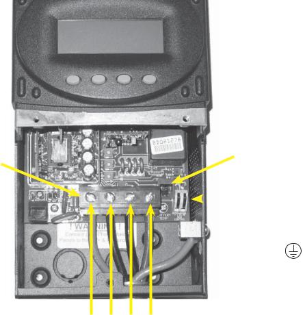
Figure 1 Field Wiring Connections and Surge Protection
Use up to 2 AWG (6.54 mm) wire and torque to 30-inch pounds/3.38 Nm at terminals.
MATE/HUB
RJ45 jack
If attaching to plywood, use a 1 5/8” wood screw to secure the MX60 at the top slotted hole and other screws as needed at interior bottom holes.
Battery Remote Temp
Sensor (RTS) RJ11 jack
Programmable AUX
Output Jack (supplies  up to 200mA @ 12 VDC
 Chassis/Equipment
Ground Lug
PV+ PVBAT- BAT+
Four-Position Terminal Block
The PV (-) and BAT (-) terminals are connected internally. Only one negative wire may be needed
to connect to the Four-Position Terminal Block if the PV - and BATconductors are bonded at the
negative bus bar. See Figures 2 and 3 for sample wiring diagrams.
NOTE: Each MX 60 requires its own PV array. DO NOT PARALLEL MX 60 PV+ AND PVTERMINALS TO THE INPUT OF THE MX60. This can cause problems with the MPPT and can cause an MX60 failure.
10
NOTES
•An optional battery Remote Temperature Sensor (RTS) is recommended for accurate battery recharging (only one RTS is needed for multiple OutBack Series Inverter/Chargers and MX60 units when an OutBack HUB and a MATE are parts of the system). When one RTS is used, it must be connected to the component plugged into the Port 1 of the HUB.
•AUX modes include powering a relay, LED indicator, and Piezo-buzzer or brushless fan.
•The OutBack MATE can display a single MX60 or multiple MX60s if connected to a HUB.
•Surge protection on the input (PV) side of the MX60 and on the battery side is required for extended warranty protection. A dwelling rooftop array requires ground fault protection (OutBack OBB-GFP-80D-125VDC-PNL recommended).
•Always install the MX60 in an upright position. The MX60 must be secured for a safe installation and to retain warranty protection. Use a 1 5/8” wood screw through the slotted hole at the top of the MX60 and at least two screws in the internally located holes at the bottom of the MX60’s enclosure.
11
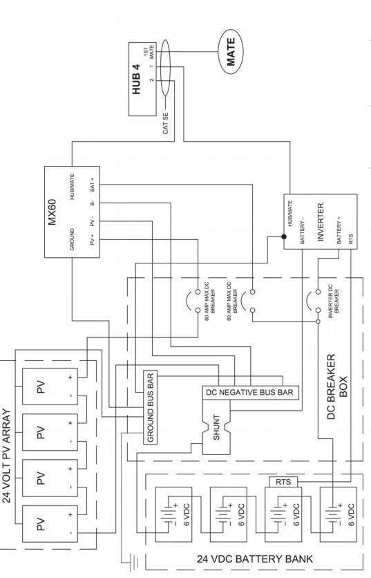
Figure 2 MX60 WIRING DIAGRAM without ground fault protection—the ground conductors tie into the
negative.
12

Figure 3 MX60 WIRING DIAGRAM with ground fault protection—the GFP/2 requires a separate ground
bus bar.
13
BATTERY SYSTEM VOLTAGE
•The MX60’s default setting is for a 12 VDC battery.
•Change the setting after powering up the MX60 if a different battery voltage is used.
•The PV array voltage—which must not exceed 150 VDC open circuit—is automatically detected.
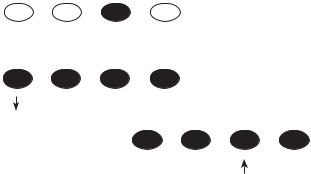
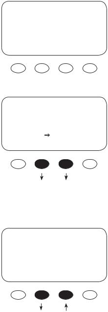
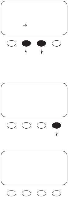
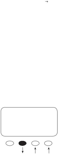
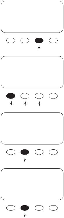
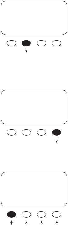
KEY TO THE EXAMPLE DIAGRAMS
Soft keys: 
(#1) (#2) (#3) (#4)
Solid black indicates key is to be pressed:
Down arrow will lead to the next screen:
Up arrow points to one or more keys that will change a value:
The keys correspond to any text immediately above them.
14
POWERING UP
The MX60 power-up sequence fi rst activates the unit and brings up a series of screens; some
screens allow the user to change the battery voltage.
NOTE: Be sure the PV input and battery breakers are off before starting the power-up sequence.
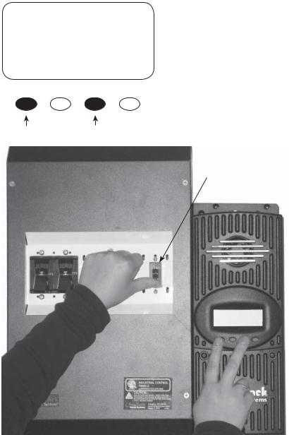
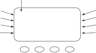
OFF SCREEN (this screen is initially blank at power up)
With the PV array and battery breakers off, press and
hold soft keys #1 and #3 and then turn on the battery
breaker (see Figure 4).
Battery Breaker
Figure 4
NOTE: The battery voltage must be at least 10.5 V or higher to power up the MX60. If the screen reads “Got Battery?” please see the Troubleshooting Guide on page 74.
15
Power-Up Screen
OutBack 12V
Power
Systems
MX60
BATTERY VOLTAGE 12 24 36 48 60
^^
EXIT ENTER
Press Either Key
Release both soft keys when the OutBack Power Systems screen appears. The selected battery voltage appears in the upper right hand corner. The BATTERY VOLTAGE screen will appear next.
NOTE: The MX60 designation in the lower left corner will read MX60AU for Australian versions and MX60ES for
Spanish versions.
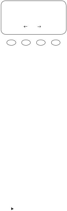
“^^” indicates the selected battery voltage. Press the “ ” or <ENTER> soft keys to proceed to the
PASSWORD screen, which prevents unauthorized changes to the system.
Password Screen
|
Press the “ – “ soft key until the password 141 shows on |
PASSWORD |
the screen. Press the <ENTER> soft key to return to the |
***150*** |
BATTERY VOLTAGE. |
ENTER - |
+ |
|
NOTE: 141 is the password for all OutBack products dis- |
|
played on a screen. |
16
Battery Voltage Screen
|
BATTERY VOLTAGE |
|||
12 |
24 |
36 |
48 |
60 |
^^ |
|
|
|
|
EXIT |
|
ENTER |
|
|
Verification Screen |
|
|
||
|
Are you sure? |
|
||
12 |
24 |
36 |
48 |
60 |
^^ |
|
|
|
|
NO |
|
|
|
Yes |
Power-Up Screen
OutBack 12V
Power
Systems
MX60
Press the “ soft key to select a battery voltage. The MX60’s default values are based on a 12 VDC system. Selecting a higher voltage system will change all the default values (e.g., the values will double with a 24 VDC system, triple with a 36 VDC system, etc.). “^^” indicates the chosen voltage. The MX60 will automatically accept the selected battery voltage if left unattended for 5 minutes in this screen. After choosing the voltage, press the <ENTER> soft key to proceed.
Press the <YES> soft key to proceed if the selected battery voltage is correct. If incorrect, press <NO> to re-enter the correct voltage.
The MX60 briefl y returns to the Power-Up screen and then automatically opens the STATUS screen which displays information regarding the recharging status. Confi rm the battery voltage displayed in the upper right corner is correct.
NOTE: Repeating the Powering Up sequence resets the MX60 Charge Controller to its factory default settings.
17
STATUS SCREEN
The STATUS screen displays system information. See page 67 for detailed information of the different Operational Modes. The optional OutBack MATE displays MX STATUS screens for convenient distant viewing from the installation location of the MX60. Please see page 71 to view the MX screens displayed on the MATE.
The PV voltage will slowly rise to the battery voltage level even when the PV breaker
is off – this is normal as the PV capacitor charges up.
PV Input Voltage |
PV 005 V |
Bat 12.5 V |
|
PV Input Current |
|||
00.0 A |
00.0 A |
||
Instantaneous Watts |
|||
Watts 0000 |
Aux Off |
||
|
|||
Daily accumulated |
kWHrs 00.0 |
Sleeping |
|
kiloWatt Hours |
|
|
Battery voltage
Output current
AUX. Status (ON or OFF) Operational Mode
NOTES
•Pressing the fi rst soft key opens the MAIN Menu screen.
•Pressing soft key #2 toggles between Amp Hours and kW Hours displays.
18

PREPARING FOR RECHARGING
PV 113 V |
Bat 12.5 V |
|
00.0 A |
00.0 A |
|
Watts |
0000 |
Aux Off |
kWHrs |
00.0 |
Sleeping |
Turn the PV input breaker on. The MX60 automatically detects the PV input voltage.
(NOTE: If PV voltage registers “000V” when the breaker is on, please check the polarity of the PV wires.)
PV 087 V |
Bat 12.5 V |
|
05.0 A |
32.9 A |
|
Watts |
0412 |
Aux Off |
kWHrs |
00.0 |
B-MPPT |
After 5 seconds of stable input voltage, the MX60 enters a “Wakeup” stage, transitions to “Sweeping” and prepares to charge the batteries by tracking the MPP of the solar array.
19
ACCESSING THE MAIN MENU
The MAIN Menu allows the user to adjust and calibrate the MX60 for maximum performance. From the STATUS screen, press soft key #1 to open the MAIN Menu screen.
*Charger |
Aux |
Light |
EQ |
Misc |
Advanced |
Logging |
Log2 |
|
EXIT |
|
GO |
Press or
or to move the asterisk “*” to the left of the desired screen. The asterisk allows access to any screen to its right.
Press the <GO> soft key after aligning the asterisk in front of the selected menu choice.
Pressing the <EXIT> soft key in the MAIN Menu returns to the STATUS Menu. Press the <EXIT> soft key in your chosen menu to return to the STATUS screen.
From the MAIN Menu, a user can choose among the following MX60 functions by aligning the asterisk:
• Charger—CHARGER SETUP
 Adjusts the Current Limit, Absorb, and Float recharging voltage set points
•Aux—AUX OUTPUT CONTROL
 Secondary control circuit for a vent fan, error alarm, and other system-related additions
•Light—BACKLIGHT CONTROL
 Adjusts the backlighting of LCD screen and soft key buttons
•EQ—BATTERY EQUALIZE
 Activates battery equalization recharging (manually or automatically)
•Misc—MISCELLANEOUS
 Additional settings and service information
•Advanced —ADVANCE MENU
 Optimizing/fi ne-tuning the MX60 (these are advanced Menus that should be left alone until the user has a good working knowledge of the MX60 and its operations)
•Logging—DATA LOGGING
 Displays recorded power production information
•Log2—LOG 2
Displays recorded peak system information
20
CHARGER SETUP
This screen allows changes to the MX60’s recharging voltage set points (Current Limit,
Absorb, Float):
• The presently selected numerical value will have an asterisk “ * ” to the left of it.
•Pressing selects the value to be changed.
•You may need to re-enter the password to change these settings.
•The default charger output current limit setting is 60 amps and is adjustable up to 70 amps. At 70 amps, a 70A or 80A breaker must be used between the battery and the MX60.
•Change ABSORB and FLOAT set points using this screen if the battery manufacturer’s recommendations are different than the default values. Otherwise, see page 80 for suggested recharging voltage set points.
•If a battery remote temperature sensor (RTS) is used, its compensated voltage values can be viewed in the MISCELLANEOUS (Misc) screen under the Tmp Comp heading.
LIMIT |
ABSORB |
FLOAT |
Amps |
Volts |
Volts |
*60.0 |
14.4 |
13.6 |
EXIT |
- + |
|
NOTE: If an RTS is used, set the ABSORB and FLOAT setting voltage based on a 25°C / 77°F setting. These are typically the manufacturer’s set points (always consult the battery manufacturer’s recommendations). If an RTS is not in use, please see the Non-Battery Temperature Compensated System values (page 86) and adjust the ABSORB/FLOAT values accordingly.
21
AUX MODE
The AUX is a secondary control circuit—essentially, a small power supply that provides a 12 VDC (up to 200 milliamps) output current. It is either active (12 VDC on) or inactive (12 VDC off ).
• To access the AUX MODE from the MAIN Menu, press the < >soft key until the asterisk is in front of the AUX selection.
•A 200 milliamps or less, 12 VDC device can be wired directly to the AUX terminal; higher output DC loads require a 12 VDC coil relay—also rated up to 200 milliamps or less for the DC coil—which itself is connected to the AUX output. An internal, re-settable Positive Temperature Coefficient (PTC) fuse protects the AUX internal components.
•For certain AUX control applications the use of a solid state relay is preferred. This is particularly benefi cial with applications such as the Diversion mode where fast switching (often called PWM control) allows a more constant battery voltage to be maintained. Both DC and AC load switching solid state relays are widely available from many sources. Eurotherm and Power-IO are two suggested solid state relay manufacturers.
•Most AUX modes or functions are designed for specialized applications and are infrequently used.
•Only one AUX MODE can operate at a time (even if other modes have been preset).
•Press the <EXIT> soft key to initiate the chosen AUX MODE.
•See Figure 5, page 30, for an AUX set-up wiring diagram.
In this Menu, ON and OFF indicators show the present state of the Aux terminals. Pressing the <ON> or <OFF> soft key changes this value.
ON indicates 12 VDC is present at the Aux output terminals. OFF indicates 0 VDC.
Terms
AUX MODE
Manual 
 Off
Off
EXIT NEXT ON OFF
The second line indicates the present mode for the Aux Output.
When the preferred mode is displayed, press the <EXIT> soft key to select it.
Pressing the <NEXT> soft key changes to the next mode.
•AUX MODE: what is displayed on the Menu
•Aux Output: 12 VDC is either available or unavailable at the Aux Terminal
•Aux Terminal: the jack to which a relay is wired
22
AUX MODE Path
*Charger |
Aux |
Light |
Charger |
*Aux |
Light |
AUX MODE |
|
|
EQ |
Misc |
Advance |
EQ |
Misc |
Advance |
Manual |
|
|
Logging |
|
Log2 |
Logging |
|
Log2 |
On |
|
|
EXIT |
|
GO |
EXIT |
|
GO |
EXIT NEXT |
ON |
OFF |
PASSWORD |
AUX MODE |
|
|
***150*** |
Manual |
|
|
ENTER - |
+ |
Off |
|
EXIT NEXT ON |
OFF |
||
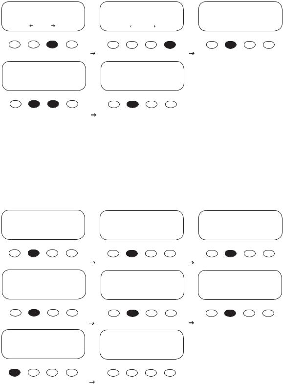
•Press the #1 soft key once from the STATUS Menu to open the MAIN Menu.
•Press either of the arrow soft keys until the “*” is to the left of Aux.
•Press the <GO> soft key. If more than ten minutes have passed since any activity, the PASSWORD screen becomes active, requiring the user to input the 141 PASSWORD and press< ENTER>. This screen will also appear after fi rst booting up the MX60 even though the password was entered when setting the battery voltage.
AUX MODE |
|
AUX MODE |
AUX MODE |
Vent Fan |
|
PV Trigger |
Float |
Off |
|
Off |
Off |
EXIT NEXT |
VOLT |
EXIT NEXT TIME VOLT |
EXIT NEXT |
AUX MODE |
AUX MODE |
AUX MODE |
ERROR ALARM |
Diversion |
Low Batt Disconnect |
On |
Off |
On |
EXIT NEXT |
EXIT NEXT TIME VOLT |
EXIT NEXT TIME VOLT |
AUX MODE |
PV 005 V |
Bat 12.5 |
V |
Remote |
00.0 A |
00.0 |
A |
Off |
Watts 0000 |
Aux Off |
|
EXIT NEXT |
kWHrs 00.0 |
Sleeping |
|
23
AUX modes in order of appearance on the MX60 display:
•Manual
•Vent Fan
•PV Trigger
•Float
•Error Alarm
•Diversion
•Low Battery Disconnect
•Remote
The most commonly used AUX modes:
•Vent Fan
•Diversion
•Low Battery Disconnect
When an AUX MODE is ON, 12 VDC is available at the AUX terminals and a condition, such as a voltage set point, is met. Other modes can be programmed in lieu of the specifi c ones listed here, but the Vent Fan mode is most easily changed (e.g., to activate an alarm instead of a fan). Here are the default AUX modes:
•Manual—pressing either the < ON> or <OFF> soft key manually activates or deactivates AUX.
•Vent Fan— when the Vent Fan voltage set point is exceeded, the vent fan will run for at least 15 seconds (the fan helps remove hydrogen from battery enclosure), even if the set point is exceeded for only a few seconds due to a surge. If the set point is exceeded for longer than 15 seconds, the fan will stay on until the voltage drops below the set point. It then takes 15 seconds before the fan shuts off. This is an external fan and not to be confused with the MX60’s internal, thermally activated fan which cools the unit.
•PV Trigger—activates an alarm or relay (that disconnects the array); when the PV input is too high and exceeds the user-determined voltage set point (should not go over 150 VDC), the PV Trigger disconnects after a minimal adjustable amount of Hold Time.
•Float—powers a load if the MX60 is producing power in the Float stage.
•Error Alarm—useful for monitoring remote sites, switches to the Off state if the MX60 has not charged the batteries for 26 hours or more (not an audible alarm, only displayed as a printed message on MX60 AUX Menu).
•Diversion—diverts excess power away from batteries when a wind or hydro generator is connected directly to the batteries.
•Low Batt Disconnect—activates/deactivates the AUX load(s) when a user-determined voltage and time levels are reached.
•Remote—allows OutBack MATE to control the operation of the AUX MODE (see MATE manual for details).
24
Programming the AUX MODES
AUX MODE
Manual
On
EXIT NEXT ON OFF
AUX MODE
Vent Fan
On |
|
EXIT NEXT |
VOLT |
VENT FAN VOLTS > 14.4
BACK - +
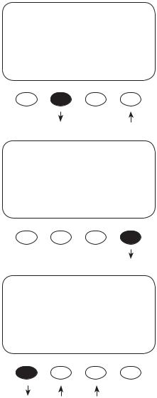
Press the <ON> or <OFF> soft keys to manually activate or deactivate AUX MODE. Press the <NEXT> soft key to view the Vent Fan screen. To view other screens, continue to press the <NEXT> soft key.
The Vent Fan helps remove hydrogen from the battery room. The ventilation fan referred to here is not the same as the MX60 cooling fan. Press the <VOLT> soft key to determine the battery voltage that will activate the AUX MODE and start the fan.
Adjust the voltage level using the < - > and < + > soft keys. Press the <BACK> soft key to return to the Vent Fan screen.
25
AUX MODE |
|
Vent Fan |
|
On |
|
EXIT NEXT |
VOLT |
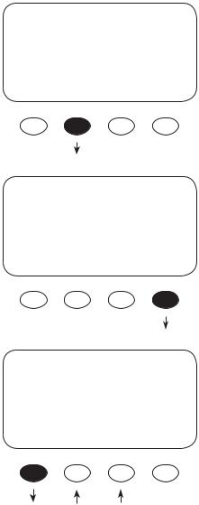
Press the <NEXT> soft key to advance to the PV Trigger soft screen.
AUX MODE
PV Trigger
Off
EXIT NEXT TIME VOLT
PV VOLTS > 140
BACK - +
When the PV input is too high and exceeds the userdetermined VOLT set point, the AUX MODE PV Trigger activates. Press the <VOLT> soft key to adjust the voltage.
Adjust the voltage within a range of 20V - 150V by pressing the < - > or < + > soft key. Press the <BACK> soft key when fi nished to return to the PV Trigger screen
26
AUX MODE
PV Trigger
On
EXIT NEXT TIME VOLT
Hold Time Sec
01.1
BACK - +
AUX MODE
PV Trigger
Off
EXIT NEXT TIME VOLT
AUX MODE
Float
Off
EXIT NEXT
To adjust the minimum amount of time the PV voltage must remain high before deactivating the AUX MODE, press the <TIME> soft key.
Press the < - > or the < + > soft key to adjust the Hold Time, then press the <BACK> soft key to return to the
PV Trigger screen. In this example, the AUX MODE will remain active for 1.1 sec after the PV voltage is below the
PV Trigger voltage before deactivating the PV Trigger and reconnecting to the array.
Press the <NEXT> soft key to view the Float screen.
The AUX MODE is active when the MX60 is in Float and producing power. Press the <NEXT> soft key to advance to the ERROR ALARM screen.
27
AUX MODE
ERROR ALARM
On
EXIT NEXT
AUX MODE
Diversion
Off
EXIT NEXT TIME VOLT
Absorb—Float—EQ
Relative Volts
|
00.0 |
00.2 |
BACK - |
+ |
HYST+ |
The default state of the ERROR ALARM is On, meaning 12 VDC is present at the AUX terminal. If the MX60 has not charged the batteries for 26 hours or more continuously, the inaudible ERROR ALARM goes into an Off state. The
ERROR ALARM is intended for remote locations to signal (e.g., a telecommunication signal to a computer) when the MX60 has not recharged for 26 hrs or more. See
MISCELLANEOUS screen 3 Err for a display of the hourly countdown. Press the <NEXT> soft key to advance to the
Diversion screen.
When external DC sources (wind, hydro) are directly connected to a battery bank, any excess power should be sent to a diversion load, such as a heating element. In
Diversion, the user programs set points—from -5.0 volts to 5.0 volts relative to the Absorb, Float and EQ voltages— to activate the AUX MODE.
This is primarily an off-grid function. Pressing the <VOLT> soft key advances to the Absorb-Float-EQ screen to adjust the voltage set points.
Use this screen to establish the set points for starting and ending the AUX MODE relative to the Absorb, Float, and EQ voltages. The < - > and < + > soft keys set the Diversion set points. The <HYST> (Hysteresis) set point establishes when the AUX MODE becomes inactive after the battery voltage falls below the Relative Volts voltage minus the HYST value. After establishing these values, press the <BACK> soft key to return to the Diversion screen (see example on next page).
28
 Loading...