


 Loading...

 powerTM ONE
Installation Manual

About OutBack Power Systems
OutBack Power Systems is a leader in advanced energy conversion technology. Our products include true sine wave inverter/chargers, maximum power point charge controllers, system communication components, as well as breaker panels, breakers, accessories, and assembled systems.
Contact Information
Telephone: |
+1.360.435.6030 (North America) |
+34.93.654.9568 (Barcelona, Spain) |
|
+1.360.618.4363 (Technical Support) |
|
|
+1.360.435.6019 (Fax) |
|
Address: |
North America |
|
|
19009 62nd Avenue NE |
|
|
Arlington, WA USA |
|
E-mail: |
Support@outbackpower.com |
|
Web Site: |
www.outbackpower.com |
|
Disclaimer
UNLESS SPECIFICALLY AGREED TO IN WRITING, OUTBACK POWER SYSTEMS:
(a)MAKES NO WARRANTY AS TO THE ACCURACY, SUFFICIENCY OR SUITABILITY OF ANY TECHNICAL OR OTHER INFORMATION PROVIDED IN ITS MANUALS OR OTHER DOCUMENTATION.
(b)ASSUMES NO RESPONSIBILITY OR LIABILITY FOR LOSS OR DAMAGE, WHETHER DIRECT, INDIRECT, CONSEQUENTIAL OR INCIDENTAL, WHICH MIGHT ARISE OUT OF THE USE OF SUCH INFORMATION. THE USE OF ANY SUCH INFORMATION WILL BE ENTIRELY AT THE USER’S RISK.
Warranty Summary
OutBack Power Systems Inc. warrants that the products it manufactures will be free from defects in materials and workmanship for a period of five (5) years subject to the conditions set forth in the warranty detail found inside the back cover of this manual.
OutBack Power Systems cannot be responsible for system failure, damages, or injury resulting from improper installation of their products.
Notice of Copyright
FLEXpower ONE™ Installation Manual ©October 2009 by OutBack Power Systems. All Rights Reserved.
Trademarks
FLEXpower ONE is a registered trademark of OutBack Power Systems. OutBack Power is a registered trademark of OutBack Power Systems.
Date and Revision
October 2009, Revision A
Part Number
900-0095-01-00 Rev A

Important Safety Instructions
READ AND SAVE THESE INSTRUCTIONS!
This manual contains important safety instructions for the FLEXpower ONE. Read all instructions and cautionary markings on the FLEXpower ONE and on any accessories or additional equipment included in the installation. Failure to adhere to these instructions could result in severe shock or possible electrocution. Exercise extreme caution at all times to prevent accidents.
Symbols Used
Symbol Description
Ground
AC Current
DC Current
Single-Phase
Sine Wave
WARNING: Hazard to Human Life
This type of notation indicates that the hazard could be harmful to human life.
CAUTION: Hazard to Equipment
This type of notation indicates that the hazard may cause damage to the equipment.
IMPORTANT:
This type of notation indicates that the information provided is important to the installation, operation and/or maintenance of the equipment. Failure to follow the recommendations in such a notation could result in voiding the equipment warranty.
Audience
These instructions are for use by qualified personnel who meet all local and governmental code requirements for licensing and training for the installation of electrical power systems with AC and DC voltage up to 240 Vac and 150 Vdc.
900-0095-01-00 Rev A |
1 |

Important Safety Instructions
Definitions
Off-Grid – Utility Grid Power is not available for use.
On-Grid – Utility Grid power is available for use. Does not imply the ability to sell power back to the utility grid.
Grid-tie, Grid-interactive, Grid-intertie – Utility Grid Power is available for use and the system is capable of returning (selling) electricity back to the utility grid.
Table 1 |
Acronyms |
|
|
|
|
Acronym |
|
Definition |
|
|
|
AC |
|
Alternating Current |
|
|
|
ANSI |
|
American National Standards Institute |
|
|
|
DC |
|
Direct Current |
|
|
|
FCC |
|
Federal Communications Commission (North America) |
|
|
|
GND |
|
Ground |
|
|
|
IEEE |
|
Institute of Electrical and Electronics Engineers |
|
|
|
N |
|
AC Neutral |
|
|
|
NEC |
|
National Electric Code (North America) |
|
|
|
NFPA |
|
National Fire Protection Association |
|
|
|
OSHA |
|
Occupational Safety and Health Association |
|
|
|
PV |
|
Photovoltaic |
|
|
|
RE |
|
Renewable Energy |
|
|
|
UL |
|
Underwriters Laboratory |
|
|
|
General Safety
WARNING: Limitations on Use
This equipment is NOT intended for use with life support equipment or other medical equipment or devices.
CAUTION: Equipment Damage
Only use components or accessories recommended or sold by OutBack Power
Systems or its authorized agents.
IMPORTANT:
Do not attempt to install this equipment if it appears to be damaged in any way. See the Troubleshooting Section for instructions on how to return the equipment if you know, or suspect, it is damaged.
2 |
900-0095-01-00 Rev A |
Important Safety Instructions
Personal Safety
WARNING: Personal Injury
This equipment weighs approximately 98 lbs (44.5 kg). Use safe lifting techniques when lifting this equipment as prescribed by the Occupational Safety and Health Association (OSHA) or other local codes.
Use standard safety equipment such as safety glasses, ear protection, steeltoed safety boots, safety hard hats, etc. as prescribed by the Occupational Safety and Health Association (or other local codes) when working on this equipment.
Use standard safety practices when working with electrical equipment (e.g., remove all jewelry, use insulated tools, wear cotton clothing, etc.)
Never work alone when installing or servicing this equipment. Have someone nearby that can come to your aid if necessary.
FLEXpower ONE System Safety
WARNING: Lethal Voltage
Review the system configuration to identify all possible sources of energy. Ensure ALL sources of power are disconnected before performing any installation or maintenance on this equipment. Confirm that the terminals are de-energized using a validated voltmeter (rated for a minimum
1000 Vac and 1000 Vdc) to verify the de-energized condition.
Do not perform any servicing other than that specified in the installation instructions unless qualified to do so or as instructed to do so by OutBack Power Systems Technical Support personnel.
WARNING: Burn Hazard
Internal parts can become hot during operation. Do not remove the cover during operation or touch any internal parts. Be sure to allow them sufficient time to cool down before attempting to perform any maintenance.
WARNING: Fire Hazard
In residential installations: check for multi-wire branch circuit wiring at the location for the installation. A possible fire hazard can exist if 120 Vac only sources (such as inverters and generators) are wired incorrectly into 120/240 Vac panels containing multi-wire branch circuits. Consult the local electric code for assistance.
Do not place combustible or flammable materials within 12 feet (3.7 m) of the equipment.
Use only the recommended cable sizes (or greater) for AC and DC conductors in compliance with local codes. Ensure all conductors and connections are in good condition. Do not operate the unit with damaged or substandard cabling.
900-0095-01-00 Rev A |
3 |
Important Safety Instructions
CAUTION: Equipment Damage
When connecting cables from the inverter to the battery terminals, ensure the proper polarity is observed. Connecting the cables incorrectly can damage or destroy the equipment.
Thoroughly inspect the equipment prior to energizing. Verify that no tools or equipment have been inadvertently left behind.
Ensure clearance requirements are strictly enforced and that all vents are clear of obstructions that can prevent proper air flow around or through the unit.
Sensitive electronics inside the equipment can be destroyed by static electricity. Be sure to discharge any static electricity built up before touching the equipment and wear appropriate protective gear.
PV Safety
WARNING: Shock Hazard
Photovoltaic (PV) arrays can be energized with minimal ambient light available. Therefore to ensure a safe disconnect from the system, be sure to install a PV disconnect, breaker, or accessible fuse box (depending on local code requirements).
CAUTION: Equipment Damage
PV Arrays must be wired with correct polarity (positive-to-positive, negative-to- negative). Connecting the cables incorrectly can damage or destroy the equipment.
Battery Safety
WARNING: Electrocution Hazard
Use the battery types recommended by OutBack Power Systems. Follow the battery manufacturer’s recommendations for installation and maintenance.
Ensure clearance requirements are strictly enforced around batteries.
Ensure the area around the batteries is well ventilated and clean of debris.
Always use insulated tools. Avoid dropping tools onto batteries or other electrical parts.
Keep plenty of fresh water and soap nearby in case battery acid contacts skin, clothing, or eyes.
If you need to remove a battery, always remove the ground terminal from the battery first. Make sure all accessories are turned off so you don’t cause a spark.
If a remote or automatic generator control system is used, disable the automatic starting circuit and/or disconnect the generator from its starting battery while performing maintenance to prevent accidental starting.
4 |
900-0095-01-00 Rev A |
Important Safety Instructions
WARNING: Fire or Burn Hazard
Ensure the cables are properly sized. Failure to size the cables properly can result in a Fire Hazard.
Wear complete eye protection and clothing protection when working with batteries. Avoid touching your eyes while working near batteries.
If battery acid contacts skin or clothing, wash immediately with soap and water. If acid enters the eye, immediately flood it with running cold water for at least 20 minutes and get medical attention immediately.
Never smoke or allow a spark or flame near the batteries.
Keep plenty of fresh water and soap nearby in case battery acid contacts skin, clothing, or eyes.
WARNING: Explosion Hazard
Never charge a frozen battery. A flooded battery discharged to 40% SOC (state- of-charge) can freeze at or below -8.9° C (16° F).
CAUTION: Equipment Damage
When connecting cables from the DC input breaker to the battery terminals, ensure proper polarity is observed (positive-to-positive, negative-to-negative). Connecting the cables incorrectly can damage or destroy the equipment.
IMPORTANT:
Baking Soda neutralizes lead-acid battery electrolyte. Vinegar neutralizes NiCad and NiFe battery electrolyte.
Have a supply of either substance readily available if using these types of batteries.
Regulatory References
National Electric Code (NEC) Article 690, (current edition)
Canadian Electrical Code, Part I (CSA 107.1)
UL 1741-2005 Static Inverter and Charge Controllers for Use in Photovoltaic Power Systems
American National Standards Institute/National Fire Protection Agency (ANSI/NFPA) 70
Recycling Information
IMPORTANT: Recycle Electronics and Batteries
Batteries are considered hazardous waste and must be recycled according to local jurisdiction. Inverters and other electronics contain metals and plastics that can (and should) be recycled. The following are some websites and phone numbers that provide information and “how” and “where” to recycle batteries and other electronic equipment.
OutBack Power Systems strongly encourages you to learn about recycling and to dispose of recyclable items accordingly. The Earth, and OutBack Power Systems, thanks you for that effort.
900-0095-01-00 Rev A |
5 |

Important Safety Instructions
Earth 911
Web site: |
www.Earth911.com |
Address: |
14646 N. Kierland Blvd., Suite 100 |
|
Scottsdale, AZ 85254 |
Phone: |
+1.480.337.3025 (direct) |
Environmental Protection Agency, USA |
|
Web site: |
www.epa.gov/recyclecity/ |
Phone: |
+1.415.947.8000 |
|
(Monday –Friday 8:00 AM to 12:00 PM and 1:00 PM to 4:00 PM PST) |
Email: |
r9.recyclecity@epa.gov |
Keep America Beautiful, USA |
|
Web site: |
www.kab.org/ |
Address: |
1010 Washington Boulevard |
|
Stamford, CT 06901 |
Phone: |
+1.203.659.3000 (Main number) |
Fax: |
+1.203.659.3001 |
Email: |
info@kab.org |
Office of Waste Management, Canada |
|
Address: |
Office of Waste Management |
|
Conservation and Protection |
|
Environment Canada |
|
Ottawa, Ontaro K1A 0H3 |
Phone: |
+1. 819.997.2800 |
Web site: |
http://www.portaec.net/library/recycling/recycling_in_canada.html |
National Institute of Recyclers, Mexico |
|
Web site: |
http://www.inare.org.mx/ |
Email: |
a57841279@prodigy.net.mx, margarita@inare.org.mx |
Phone: |
55.57.85.9160 |
Fax: |
55.57.84.1279 |
EuroRecycle.net
The following website provides general information about Recycling in Europe. It also provides a list of companies and organizations that provide recycling information or assistance.
Web site: http://euro.recycle.net/assn/index.html
E-mail: http://euro.recycle.net/cgi-bin/feedback1.cgi?w=27
(This is an online form providing a means to contact the owners of the website.)
6 |
900-0095-01-00 Rev A |

|
Table of Contents |
Important Safety Instructions |
...................................................................1 |
Symbols Used ........................................................................................................................................................................ |
1 |
Audience ................................................................................................................................................................................. |
1 |
Definitions............................................................................................................................................................................... |
2 |
General Safety ....................................................................................................................................................................... |
2 |
Personal Safety...................................................................................................................................................................... |
3 |
FLEXpower ONE System Safety....................................................................................................................................... |
3 |
PV Safety.................................................................................................................................................................................. |
4 |
Battery Safety......................................................................................................................................................................... |
4 |
Regulatory References........................................................................................................................................................ |
5 |
Recycling Information ........................................................................................................................................................ |
5 |
Earth 911 ............................................................................................................................................................................................. |
6 |
Environmental Protection Agency, USA................................................................................................................................... |
6 |
Keep America Beautiful, USA ....................................................................................................................................................... |
6 |
Office of Waste Management, Canada ..................................................................................................................................... |
6 |
National Institute of Recyclers, Mexico..................................................................................................................................... |
6 |
EuroRecycle.net ................................................................................................................................................................................ |
6 |
Introduction............................................................................................. |
11 |
Components ....................................................................................................................................................................... |
12 |
Applications ........................................................................................................................................................................ |
13 |
On-Grid Applications .................................................................................................................................................................... |
13 |
Off-Grid Applications .................................................................................................................................................................... |
14 |
Grid-Interactive Applications ..................................................................................................................................................... |
14 |
PV Array Planning .......................................................................................................................................................................... |
15 |
Battery Bank Planning .................................................................................................................................................................. |
15 |
Generator Requirements................................................................................................................................................ |
16 |
Preparation.......................................................................................................................................................................... |
17 |
Tools Required ................................................................................................................................................................................ |
17 |
Materials Required......................................................................................................................................................................... |
17 |
Accessories....................................................................................................................................................................................... |
17 |
Location............................................................................................................................................................................................. |
17 |
Environmental................................................................................................................................................................................. |
17 |
Clearance and Access Requirements ......................................................................................................................... |
18 |
Dimensions.......................................................................................................................................................................... |
19 |
Conduit and Knockout Preparation............................................................................................................................ |
20 |
Mounting.............................................................................................................................................................................. |
21 |
Removing the Covers....................................................................................................................................................... |
24 |
Accessing the Wiring Compartments ........................................................................................................................ |
25 |
Wiring .................................................................................................................................................................................... |
26 |
Grounding ........................................................................................................................................................................................ |
26 |
DC Connections.............................................................................................................................................................................. |
27 |
900-0095-01-00 Rev A |
7 |

|
Table of Contents |
AC Connections .............................................................................................................................................................................. |
31 |
Functional Test/Commissioning.................................................................................................................................. |
33 |
Pre-startup Procedures ................................................................................................................................................................ |
33 |
Energize/Startup ............................................................................................................................................................................ |
33 |
Reassembling the Enclosures ....................................................................................................................................... |
35 |
Operation................................................................................................. |
39 |
Setting Basic Parameters ................................................................................................................................................ |
39 |
MATE2 Settings............................................................................................................................................................................... |
39 |
Charger Settings............................................................................................................................................................................. |
39 |
Setting Time, Date & Display on the MATE2 ......................................................................................................................... |
40 |
Selecting the AC Source and AC Input Limit on the Inverter .......................................................................................... |
42 |
Accessing the Advanced Menu................................................................................................................................................. |
43 |
Setting Battery Amp-Hours and Return Amps using the FLEXnet DC Monitor ........................................................ |
44 |
Setting Charging Parameters..................................................................................................................................................... |
45 |
De-energize/Shutdown ............................................................................................................................................................... |
46 |
Specifications........................................................................................... |
49 |
Feature Matrix .................................................................................................................................................................... |
49 |
Electrical Specifications, 120 Vac/60 Hz Models .................................................................................................... |
50 |
Mechanical Specifications, 120 Vac/60 Hz Models................................................................................................ |
50 |
Electrical Specifications, 230 Vac/50 Hz Models .................................................................................................... |
51 |
Mechanical Specifications, 230 Vac/50 Hz Models................................................................................................ |
51 |
Surge Protector.................................................................................................................................................................. |
52 |
LEDs .................................................................................................................................................................................................... |
52 |
Renewable Energy Input & Storage............................................................................................................................ |
53 |
PV Sizing............................................................................................................................................................................................ |
53 |
Battery Bank Sizing........................................................................................................................................................................ |
53 |
Amp-Hour Requirements ............................................................................................................................................................ |
53 |
Wiring Configurations ............................................................................. |
59 |
FLEXpower ONE with FLEXnet DC Monitor and GFDI.......................................................................................... |
61 |
FLEXpower ONE with FLEXnet DC Monitor Only (no GFDI)............................................................................... |
62 |
FLEXpower ONE with GFDI Only (no FLEXnet DC Monitor)............................................................................... |
63 |
FLEXpower ONE (no FLEXnet DC Monitor or GFDI) .............................................................................................. |
64 |
Warranty .................................................................................................. |
65 |
How to Arrange for Warranty Service ........................................................................................................................ |
66 |
Return Material Authorization (RMA)...................................................................................................................................... |
66 |
Returning Product to OutBack .................................................................................................................................................. |
66 |
Index ........................................................................................................ |
67 |
8 |
900-0095-01-00 Rev A |
Table of Contents
|
List of Tables |
|
Table 1 |
Acronyms.............................................................................................................................................................................. |
2 |
Table 2 |
Basic Components of a FLEXpower ONE System.................................................................................................. |
12 |
Table 3 |
Ground Conductor Size and Torque Requirements............................................................................................. |
26 |
Table 4 |
DC Conductor Size and Torque Requirements...................................................................................................... |
27 |
Table 5 |
AC Conductor Size and Torque Requirements ...................................................................................................... |
31 |
Table 6 |
Feature Matrix................................................................................................................................................................... |
49 |
Table 7 |
Worksheet for Determining Average Daily Load in Amp-hours ............................................................ |
56 |
Table 8 |
Worksheet for Determining Battery Bank Size ................................................................................................. |
57 |
900-0095-01-00 Rev A |
9 |

Table of Contents
|
List of Figures |
|
Figure 1 |
FLEXpower ONE System Overview ............................................................................................................................ |
11 |
Figure 2 |
Basic Components of a FLEXpower ONE System.................................................................................................. |
12 |
Figure 3 |
On-Grid Applications (Example) ................................................................................................................................. |
13 |
Figure 4 |
Off-Grid Applications (Example)................................................................................................................................. |
14 |
Figure 5 |
Grid-Interactive Applications (Example).................................................................................................................. |
14 |
Figure 6 |
Clearance and Access Requirements ........................................................................................................................ |
18 |
Figure 7 |
Dimensions ........................................................................................................................................................................ |
19 |
Figure 8 |
Conduit and Knockout Preparation........................................................................................................................... |
20 |
Figure 9 |
Installing the Mounting Bracket ................................................................................................................................. |
22 |
Figure 10 |
Attaching the Mounting Plate to the Mounting Bracket ................................................................................... |
23 |
Figure 11 |
Removing the Covers ..................................................................................................................................................... |
24 |
Figure 12 |
Wiring and Breaker Compartment............................................................................................................................. |
25 |
Figure 13 |
Ground Connections ...................................................................................................................................................... |
27 |
Figure 14 |
Battery Connections with the FLEXnet DC Monitor............................................................................................. |
28 |
Figure 15 |
Battery Connections without the FLEXnet DC....................................................................................................... |
29 |
Figure 16 |
PV Connections with a FLEXnet DC Monitor.......................................................................................................... |
30 |
Figure 17 |
AC IN Connections........................................................................................................................................................... |
31 |
Figure 18 |
AC OUT Connections ...................................................................................................................................................... |
32 |
Figure 19 |
Energize Procedures....................................................................................................................................................... |
33 |
Figure 20 |
Functional Test Procedures for Initial Startup........................................................................................................ |
34 |
Figure 21 |
Replacing the Raceway and FLEXmax 80 Front Cover........................................................................................ |
35 |
Figure 22 |
Replacing the Inverter’s AC Terminal Access Cover............................................................................................. |
35 |
Figure 23 |
Replacing the AC Enclosure Front Cover................................................................................................................. |
36 |
Figure 24 |
Replacing the AC Enclosure Top Cover.................................................................................................................... |
36 |
Figure 25 |
Replacing the DC Enclosure Front Cover................................................................................................................. |
37 |
Figure 26 |
Replacing the DC Cover................................................................................................................................................. |
37 |
Figure 27 |
MATE2 Setup Screen (Page 1) ..................................................................................................................................... |
40 |
Figure 28 |
MATE2 Setup Screen (Page 2 and 3) ......................................................................................................................... |
41 |
Figure 29 |
Inverter Setup Screen – Selecting AC Source......................................................................................................... |
42 |
Figure 30 |
Accessing the Advanced Menus................................................................................................................................. |
43 |
Figure 31 |
Setting Battery Amp-hours and Return Amps ....................................................................................................... |
44 |
Figure 32 |
Setting Input Source and Current Limit................................................................................................................... |
45 |
Figure 33 |
Shutdown Procedures.................................................................................................................................................... |
46 |
Figure 34 |
Functional Test Procedures to Confirm the Unit is De-energized................................................................... |
47 |
Figure 35 |
FLEXpower ONE with FLEXnet DC Monitor and GFDI......................................................................................... |
61 |
Figure 36 |
FLEXpower ONE with FLEXnet DC Monitor Only (No GFDI).............................................................................. |
62 |
Figure 37 |
FLEXpower ONE with GFDI Only (no FLEXnet DC Monitor) .............................................................................. |
63 |
Figure 38 |
FLEXpower ONE (no FLEXnet DC Monitor or GFDI) ............................................................................................. |
64 |
10 |
900-0095-01-00 Rev A |
Introduction
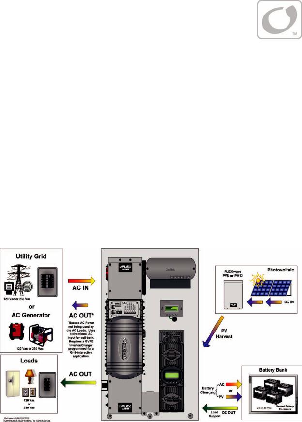
Thank you for choosing a FLEXpower ONE System from OutBack Power Systems. FLEXpower ONE is an integrated power system solution designed to be quick to install and easy to use.
The FLEXpower ONE System is intended for off-grid and on-grid applications up to 3.6 kW. It is intended for use with photovoltaic (PV) modules for harvesting energy and a battery bank for energy storage. FLEXpower ONE can also be configured as “Grid-interactive” meaning that excess energy (energy that exceeds usage) will be returned to the Grid (Sell Mode).
The FLEXpower ONE System is designed with the following features:
3.5 kW and 3.6 kW units.
120 Vac/60 Hz configurations and 230/50 Hz configurations
Rated for Indoor Installations
Includes mounting bracket for wall-mounting
Charge controller uses MPPT technology to maximize the harvest from solar modules
Grid-interactive capable (requires a configuration that features a GVFX Inverter)
Battery status monitor takes independent shunt measurements of PV and inverter power
Includes OutBack’s Surge Protector for additional protection against damaging power surges
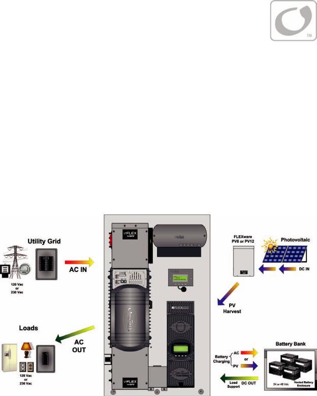
Figure 1 FLEXpower ONE System Overview
900-0095-01-00 Rev A |
11 |

Introduction
Components
A complete FLEXpower ONE is composed of the following components. See page 49 for details on specific configurations.
Table 2 |
Basic Components of a FLEXpower ONE System |
|||
|
|
|
|
|
Components |
|
Documentation |
|
|
|
|
|
|
|
FX Series Inverter/Charger (VFX or GVFX) |
|
FLEXpower ONE Installation Manual (this book) |
|
|
Mounting Plate (with mounting bracket) |
|
|
|
|
MATE Remote Control and Display |
|
|
|
|
AC Enclosure (120 V-NA or 230 V-EU) |
|
Additional Reference Documents |
|
|
DC Enclosure (125, 175, or 250A) |
|
MATE Installation and User’s Manual |
|
|
FLEXnet DC Battery Monitor |
|
FLEXnet DC Monitor |
|
|
FLEXmax 80 Charge Controller |
|
FX or Grid-Interactive Programming Manual |
|
|
Raceway |
|
|
FLEXmax 80 User’s Manual |
|
HUB4 Communication Manager |
|
HUB4 Communication Manager User’s Manual |
|
|
FLEXware Surge Protector |
|
|
|
|
|
|
|
FLEXnet DC Battery Monitor |
|
|
FW250-AC-120V-NA |
|
HUB4 Communication Manager |
|
|
Or |
|
||
|
FW250-AC-230V EU |
|
|
|
FLEXware Surge Protector |
|
|
|
|
(mounted under AC cover) |
|
|
|
|
|
|
|
MATE2 Remote Control |
|
|
FX Series |
|
|
|
|
Inverter/Charger |
|
|
|
|
|
|
FLEXmax 80 Charge Controller |
|
|
FW250-DC-125, |
|
Mounting Plate |
|
|
FW250-DC-150, |
|
||
|
or |
|
|
|
|
FW250-DC 250 |
|
|
|
Raceway
Figure 2 Basic Components of a FLEXpower ONE System
12 |
900-0095-01-00 Rev A |
Planning
Applications
The FLEXpower ONE is intended for on-grid, off-grid, and grid-interactive applications. It is designed to use photovoltaic (PV) panels to harvest solar energy and a battery bank to store the harvested energy.
On-Grid Applications
In on-grid applications, the FLEXpower ONE can use the grid power as the primary power source or as the backup source of power. If the FLEXpower ONE is used as backup to the grid, the FLEXpower ONE will take over when the grid fails. If the FLEXpower ONE is used as the primary source, the grid power will be used when the batteries have been drained. In this situation, the AC power or PV harvest can be used to recharge the battery bank.
Figure 3 On-Grid Applications (Example)
900-0095-01-00 Rev A |
13 |

Planning
Off-Grid Applications
In off-grid applications, the FLEXpower ONE can use the harvested energy from the battery bank as the primary power source. An AC generator can also be connected to support the system
when required.
Figure 4 Off-Grid Applications (Example)
Grid-Interactive Applications
In grid-interactive applications, grid power is used to run the loads. When excess PV is available from the batteries, the FLEXpower ONE supports those loads with the PV. When the PV exceeds the load requirements, the FLEXpower ONE sells that excess power back through its input, to the utility grid. When the utility grid is not available, the FLEXpower ONE takes over to run the loads with PV and energy stored in the battery bank.
Figure 5 Grid-Interactive Applications (Example)
14 |
900-0095-01-00 Rev A |

Planning
PV Array Planning
The FLEXpower ONE is designed to use PV input to charge the battery bank. The FLEXmax 80 charge controller(s) integrated into the FLEXpower ONE System uses Maximum Power Point Tracking (MPPT) technology to maximize the PV harvest. A PV Combiner box (not included) may be required for multiple PV strings. PV Combiner Boxes are available from OutBack Power Systems for 8 to 12
PV strings.
FLEXpower ONE includes one FLEXmax 80 Charge Controller. The charge controller allows input from a single PV array. The PV input can support the following PV configuration.
4,000 WSTC on 48 Vdc system, 2,000 WSTC on 24 Vdc system
150 VOC including local temperature correction factor per NEC 690.7
64 A ISC maximum PV array current per NEC 690.8
For a PV Planning Tool, see the following website.
http://outbackpower.com/resources/string_sizing_tool/
Battery Bank Planning
Types of Batteries
The FLEXpower ONE System supports a 24 or 48 Vdc battery bank, depending on the inverter that is featured in the configuration. Before constructing a battery bank, check the model number on the side of the inverter to confirm the nominal battery voltage.
A vented enclosure for the battery bank may be required by electric code.
Bank Sizing
In general, the size of the loads (watts) and the required backup period (hours) will determine best size for the battery bank. To calculate this, use the information provided on page 53 through page 57. Worksheets are provided for assistance.
900-0095-01-00 Rev A |
15 |

Planning
Generator Requirements
IMPORTANT:
All connections must comply with local electric code.
Generator grounding and neutral-to-ground bonding should be provided in accordance with specific system configuration and national/local code requirements.
Follow the manufacturer’s recommendations for fuel type and maintenance.
The following are general requirements for using a generator with the FLEXpower ONE.
Electrical Requirements
~North American Applications: 120 Vac / 60 Hz
~European Applications: 230 Vac / 50 Hz
Minimum available generator power* should be equal to or greater than nominal inverter rating (*after de-ratings for peak verses continuous power, for load power factor considerations, for altitude, and for ambient temperature).
~A generator with a de-rated power specification smaller than that of the inverter may not be able to handle all downstream AC loads and/or the built-in battery charger.
~A generator with a de-rated power specification larger that that of the inverter may be required to handle the built-in battery charger as well as all downstream AC loads.
~Available power from the generator may be further limited by ratings for circuit breakers and/or generator output connectors. “Full” generator output power may not be available from a single generator connector.
~Generator sizing may be affected by start-up surge current requirements of 3X to 6X normal operating current for some loads (i.e., motors with large loads).
~The inverter and/or downstream loads may have difficulty operating from poorly-regulated generators (voltage, frequency, load).
Grid-interactive inverters typically require inverter-type generators.
Split-phase generators (i.e., 120/240 Vac / 60 Hz) can be adapted to a single-phase inverter using an autotransformer such as the X-240. For additional information, see…
~PSX-240 Manual: http://www.outbackpower.com/pdf/manuals/PSX-240_Installation Manual.pdf
~X-240 Manual: http://www.outbackpower.com/pdf/manuals/fw-x240.pdf
The OutBack MATE can be used to program an inverter’s AUX output to start and stop a generator. This 12 V output can often control a two-wire-start generator directly. Three-wire-start generators require an interface such as an Atkinson module. For additional information, see…
~OutBack Power Systems AGS Brochure: http://www.outbackpower.com/pdf/brochures/Automatic_Generator_Start.pdf
~OutBack Power Systems MATE Manual: http://www.outbackpower.com/pdf/manuals/mate.pdf
~Atkinson Electronics: http://atkinsonelectronics.com/
16 |
900-0095-01-00 Rev A |

Planning
Preparation
Tools Required
The following tools may be required for installing this equipment.
Wire cutters/strippers |
Drill and drill-bits |
||
|
Torque wrenches |
|
Ratchet drives |
|
Assorted insulated screw-drivers |
|
Digital Voltmeter |
Materials Required
The following materials may be required for installing this equipment.
Conductors for wiring
Conduits, bushings
Anchor Bolts (x4) or Dry-wall (x6) screws for mounting
Plywood (optional, for additional wall support)
Accessories
The following accessories are available for purchase.
PV8/PV12 Combiner Box
See the OutBack catalog for a complete list of other parts and components that are available.
Location
FLEXpower ONE is rated for indoor installations.
In areas where seismic activity is a concern, consult local code for seismic safety requirements.
Environmental
This unit is performance rated at 25°C (77°F). Exposure to extreme hot temperatures can reduce the unit’s performance. When used in an outdoor installation, use a shading structure to avoid direct exposure to sunlight.
The mounting surface should be vertical, smooth, and able to support three (3) times the weight of the enclosure (98 lb, or 44.5 kg. This may require additional support for wall-mounted installations.
900-0095-01-00 Rev A |
17 |

Planning
Clearance and Access Requirements
WARNING: Fire/Explosion Hazard
Do not place combustible or flammable materials within 12 feet (3.7 m) of the equipment. This unit employs mechanical relays and is not ignition-
protected. Fumes or spills from flammable materials could be ignited by sparks.
IMPORTANT:
Clearance and access requirements may vary by location. Maintaining a 36” (0.91 cm) clear space in front of the system for access is recommended. Consult local electric code to confirm clearance and access requirements for the specific location.
12” (30.5 cm) |
Minimum recommended |
|
clearance above and on sides. |
||
(Minimum) |
||
|
12” (30.5 cm) |
12” (30.5 cm) |
(Minimum) |
(Minimum) |
Side View
36” (91.4 cm) (Minimum)
Minimum recommended clearance in front.
Figure 6 Clearance and Access Requirements
18 |
900-0095-01-00 Rev A |
Planning
Dimensions
19¾” (481 cm)
16” (41 cm)
Mounting Bracket
≈13” (33 cm)
33½” (851 cm)
Side View
Figure 7 |
Dimensions |
900-0095-01-00 Rev A |
19 |

Planning
Conduit and Knockout Preparation
Knockouts (two 1”, one 2”) are provided on the ends of the AC and DC enclosures for routing cable into the enclosures. Conduit and bushings are recommended to prevent damage to conductors from sharp edges along knockout holes.
1.Remove the 2” knockout on the DC end to accommodate the larger battery cables and Remote Temperature Sensor cable.
2.Remove the 1” knockout(s) on the AC end to accommodate the AC cabling.
3.Install conduit and bushings to protect the cable from damage from the sharp edges of the hole.
4.Ensure no debris or metal shavings have fallen into the enclosures.
AC End
1” |
2” |
|
Top View
Front Side
Front Side
Bottom View
1” |
2” |
DC End
Figure 8 Conduit and Knockout Preparation
20 |
900-0095-01-00 Rev A |
Loading...