

Page 1

FX Circuit Board Replacement Instructions
There are three circuit boards inside the FX inverter. Normally, only two of
these boards are candidates for replacement; the FET board (large board that
includes the battery terminals) and the control board (smallest board that includes
the microprocessors). In some cases, however, the AC assembly (the “L”-shaped
boards that include the AC terminal block) is defective.
Tools required to service the FX are:
• #2 Phillips screwdriver
• 3/8” flat blade screwdriver
• 4mm hex wrench (included with the boards shipped to you)
• 10mm deep socket on a 12” extension with ratchet
• 10mm wrenches (2 of them would be nice)
• Rubber-band wrench (usually used for opening jars)
• Flashlight
• 9-volt batteries (three if you have a 12V or 24V FX, six for a 48V FX)
The FET board is the “brawn” of the system. It processes all of the high
current to and from the battery. This board contains the drive and overcurrent
protection circuits. In general, when an inverter fails, it is often the power FETs
that go. The FX is designed such that in the event of a FET failure, you replace
only the one assembly. There are two green LED’s on the FET board that help to
diagnose problems.
The control board is the “brains” of the inverter. It contains all of the
processing power as well as the unit’s memory. The processors and memory are
programmable and therefore possible to upgrade. It may be possible in the future to
download new code into the control board in the field, but for now we will have to
live with board swapping. There are either 15 or 20 (depending on the age of the
board) green LED’s on the back of the control board to help diagnose problems
with it.
The AC assembly is the I/O (Input/Output) portion of the FX. The AC
assembly consists of the AC board and the connector board. They are soldered
together to form one “L”-shaped assembly. This AC assembly will rarely require
repair or upgrade.
Once you have determined that the FX must come apart, use the following
guidelines to disassemble, repair, test and reassemble the unit. Repair should be
Installation & Programming Manual FX Circuit Board Replacement Copyright 2003 OutBack Power Systems, Inc.
Page 1 Rev 2.0 10/26/04 Tel 360 435 6030 Fax 360 435 6019
900-0042-1 19009 62nd Ave NE, Arlington WA 98223 USA
Page 2
able to be done in the field although installers may want to take the FX back to the
shop (where the power actually works) for verification testing.
STEP 1:
Turn off all breakers feeding into and out of the AC and DC leads. Disconnect
the AC and battery connections. Unless you want to get really frustrated when
you try to put the unit back together, take the extra 2 minutes to remove the unit
from the wall so that you can work in the “gravity assist” position. (You may
really hate life if you don’t do this)
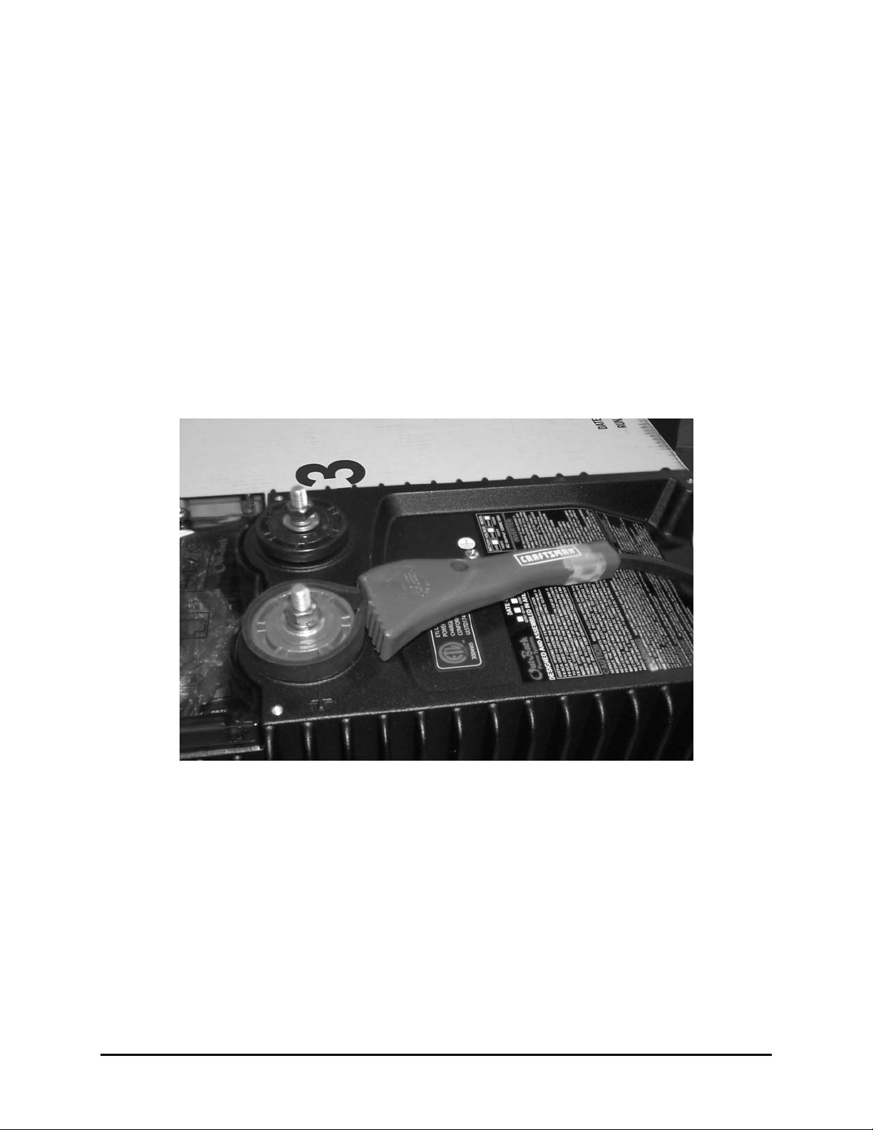
STEP 2:
Remove the red and black plastic nuts with the rubber-band wrench (Figure 1). It
doesn’t scratch or dent anything. Break down, go to Sears and get yourself one, (It
opens jars too!) or else use a flat bladed screwdriver like you are loosing up a
conduit locknut.
Figure 1
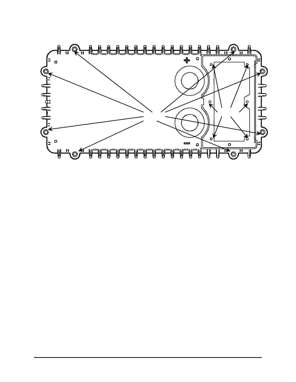
STEP 3:
Use a #2 Phillips tip screwdriver and remove the six screws inside the AC
wiring compartment (Figure 2, Phillips). These are 6-32 x ½” stainless steel pan
head screws (In case you lose any). Before getting into the unit you need to
make sure you do not have a static charge built up on you or your clothes. The
safest way to accomplish this is to stand naked in a mud puddle while
disassembling the inverter. Another method would be to make sure you are
wearing only 100% cotton clothes. Cotton does not build up a static charge. In
addition, ground yourself by touching something like a water pipe, electrical
ground conductor etc. in order to bleed off any charge. Static can destroy
Installation & Programming Manual FX Circuit Board Replacement Copyright 2003 OutBack Power Systems, Inc.
Page 2 Rev 2.0 10/26/04 Tel 360 435 6030 Fax 360 435 6019
900-0042-1 19009 62nd Ave NE, Arlington WA 98223 USA
Page 3
boards. The form of static that is harmful is much less than what actually
makes sparks. 30 volts can damage parts, so don’t take chances and don’t
handle any boards unless static control measures have been taken.
Hex
Phillips
Figure 2
STEP 4:
Pay attention to this one or you’ll hate yourself later! Use a 4mm Allen wrench
(included) to remove the 8 stainless steel socket head cap screws that connect
the top to the bottom casting (Figure 2, Hex). The FX has a fan mounted to the
top cover. It plugs into the FET board. If you pull the top cover off without
thinking, it will rip the wires right out of the connector. (This is where you will
start swearing and your customer will become alarmed!) If this happens, you
have two choices. 1: get new Molex crimp terminals and the special crimp tool
to correctly fix the problem, or 2: solder the wires onto the sockets that are still
attached to the mating connector on the FET board. Hint: cut some of the plastic
away first so you can get to the pins. The red wire goes towards the bottom
casting (the latch side of the connector). Figure 3 gives you an idea how long
the wires are. There are two small O-rings that fit into slots of the battery
terminals. If they aren’t in their slots, they may be stuck to the underside of the
top cover. Remove these small O-rings so they don’t get lost. There is also a
very large O-ring that travels the perimeter of the chassis. This doesn’t need to
be removed but if it comes out it should be reinstalled before the top cover is
put back on. If this O-ring is too small, it can be stretched. The last thing that
should be noted is the square piece of “Nomex” attached to the underside of the
top cover (see Figure 3). Sometimes this piece falls out or is loose. If this is the
case please use some silicone to glue it back in place. Make sure it is fairly dry
before attaching the top cover.
Installation & Programming Manual FX Circuit Board Replacement Copyright 2003 OutBack Power Systems, Inc.
Page 3 Rev 2.0 10/26/04 Tel 360 435 6030 Fax 360 435 6019
900-0042-1 19009 62nd Ave NE, Arlington WA 98223 USA
Page 4

Wire Connection
to FET Board
STEP 5:
Determine which board or boards need replacing. Luckily, we’ve sent you
boards that look identical or very similar to the boards that need replacing (you
can thank us later). It may be the case, though rare, that one of the boards that
we didn’t send you is damaged. Please take a quick look around to see if
anything is fishy (black soot, burnt circuit board, cracked IC’s, etc). A flashlight
can be used for this procedure and can be done without removing any boards.
STEP 6:
Next, remove the two ribbon cables (Figures 4 & 5) that connect the FET board
and the AC assembly to the Control board. To remove the ribbon cables, use the
levers at the top and bottom of the ribbon cable connections.
“Nomex”
Figure 3
Figure 4 Figure 5
Installation & Programming Manual FX Circuit Board Replacement Copyright 2003 OutBack Power Systems, Inc.
Page 4 Rev 2.0 10/26/04 Tel 360 435 6030 Fax 360 435 6019
900-0042-1 19009 62nd Ave NE, Arlington WA 98223 USA
Page 5

STEP 7:
Now you get to remove the boards you want to replace.
CONTROL BOARD:
Lift up on the AC assembly as shown in Figure 6 until you start pulling on
the white and black AC output wires (located near the bottom of the AC
assembly). You will have just enough room to sneak the control board out.
Figure 6
AC ASSEMBLY:
Figure 7 shows the AC output wires. They must be disconnected to remove
the AC assembly. The white Neutral wire is on the bottom and the black Hot
wire is above it. Disconnect them by pulling them directly out from the
board. It may help to keep the AC Assembly in the slot and using needle
nose pliers when unplugging these tight wires.
AC Output Hot!
AC Output Neutral
Spiky Looking
Things
Figure 7
Installation & Programming Manual FX Circuit Board Replacement Copyright 2003 OutBack Power Systems, Inc.
Page 5 Rev 2.0 10/26/04 Tel 360 435 6030 Fax 360 435 6019
900-0042-1 19009 62nd Ave NE, Arlington WA 98223 USA
Page 6

FET BOARD:
Replacing the FET board requires removal of the ribbon cables as well as 2
bolts that hold the FET board in place. Bolt #1 will require a ratchet with a
deep 10mm socket and a 12” extension (see Figure 8). Bolt #2 will require
the two 10mm wrenches (see Figure 8). Pay attention to the washers when
removing the bolts. The larger flat washer makes contact with the copper
busbars. The smaller lock washer is between the flat washer and the bolt
head. The bolts are 6mm .1 x 16mm in case they get lost. The bolts are
stainless steel and therefore non-magnetic, so when you drop one into the
chassis don’t waste your time looking for a magnet. The bolts are tightened
into connecting busbars that have pressed in nuts. You do not need to get
your fingers underneath to retighten. The third thing that may need to be
disconnected (depending on the model) is the “Thermister” clip, located
underneath the ribbon cable connector (see Figure 8). This is most easily
done after removing the bolts by lifting the FET board up until you can get
your hand down there (a small child may be used for this operation, just
kidding). The “Thermister” clip pulls off with a little bit of force. Make sure
you retrieve any pieces of hardware that you may have dropped inside.
Thermister
Clip
Bolt #1
STEP 8:
Bolt #2
Figure 8
Reassemble: Install the new board or boards making sure that anti-static
procedures have been observed.
FET BOARD: Check the FET board to see if the “Thermister” connecter has a
“Thermister” clip already installed. Remove it if you have the “Thermister” clip
Installation & Programming Manual FX Circuit Board Replacement Copyright 2003 OutBack Power Systems, Inc.
Page 6 Rev 2.0 10/26/04 Tel 360 435 6030 Fax 360 435 6019
900-0042-1 19009 62nd Ave NE, Arlington WA 98223 USA
Page 7

in the chassis of your FX. Guide the FET board into the proper slot in the
chassis and lower it ½ way down. If necessary, plug in the “Thermister” clip to
its connector. Slide the FET board all the way down making sure that the AC
output wires go through the gap on the bottom of the FET board. Bolt down the
FET board and make sure they are tightened to 106 inch pounds.
AC ASSEMBLY & CONTROL BOARD: Slide the AC assembly ½ way down
its slot. Connect the AC output wires to the AC assembly starting with the white
wire (on bottom) and then the black wire (on top). With the AC assembly lifted
up as high as possible, insert the Control board in its slot but do not lower it yet.
There is a “Lip” on most of the AC assemblies that fits over the top edge of the
Control board. Some AC assemblies don’t have this feature. If the “Lip” is
present make sure it is over the edge of the Control board. At this point lower
both boards down to the bottom making sure they are in their slots (very
important, check this). Don’t push them down because the AC output wires
may be lodged underneath the AC assembly. With a flashlight, check that the
AC output wires go through the gap provided at the bottom of the AC assembly.
STEP 9:
Once the boards are properly seated and attached, you need to install the ribbon
cables, the AC gasket and the O-rings.
RIBBON CABLES: There are two ribbon cables that are identical but since
they fit into two different spaces they need to be pre-bent in two different ways.
Figure 9 shows the proper bending of the ribbon cable that connects the Control
board to the AC assembly. Figure 10 shows the proper bending of the ribbon
cable that connects the Control board to the FET board. This one is a little
tricky. The ribbon cables have a polarity feature so make sure the notches are in
the correct places. If not, flip the ribbon cable and try again.
Connection to
Control Board
Notches
Connection to
AC Assembly
Figure 9 Figure 10
Install the ribbon cables between the boards following the connection
instructions in Figures 9 & 10. After making the “Connection to the FET
Installation & Programming Manual FX Circuit Board Replacement Copyright 2003 OutBack Power Systems, Inc.
Page 7 Rev 2.0 10/26/04 Tel 360 435 6030 Fax 360 435 6019
900-0042-1 19009 62nd Ave NE, Arlington WA 98223 USA
Connection
to FET Board
Page 8

Board”, curl the “Bend” in the ribbon cable towards the inside of the FX. This
will pull the ribbon cable inward and then it will be less likely to be pinched
between the chassis and the top cover when you put on the top cover. This is a
major source of problems, pinching the ribbon cable will destroy the boards!
Make sure the ribbon cables are pushed all the way in and then tape the ribbon
cable to the clear relay if necessary. Again, be sure the boards are all in their
respective card guides. The AC board especially likes to go off to one side or
the other if you are not careful.
AC GASKET: Between the AC assembly and the top cover is a gasket that
keeps water from entering and also functions as isolation. Some AC assemblies
have this AC gasket permanently attached while some don’t. If you have
received a new AC assembly chances are it will come with a separate AC
gasket. This gasket has six holes for screws to pass through. Place the AC
gasket on the AC assembly so that the holes in the gasket line up with the holes
in the AC assembly.
O-RINGS: There are two small O-rings that need to be placed in the slots on the
FET board battery terminals. They may be stuck to the underside of the top
cover or they may have stayed in the FET board itself. These O-rings are
necessary if you have a “Sealed” FX that is in a corrosive environment. If not
then you may lose them and not feel too stressed out. There is also a very large
O-ring that fits in the slot that travels the perimeter of the chassis. It also may be
stuck to the top cover or it may be in the slot already. Same deal applies to your
stress level.
STEP 10:
Test: Now that the unit is electrically back together, it should be tested on a
bench power supply or a series of 9-volt batteries prior to applying battery
power. For 12-volt and 24-volt FX’s use three 9-volt batteries in series
(alligator clips work nicely) but for 48 volt FX’s use at least five maybe six 9volt batteries in series. These batteries will probably be toast afterwards but it’s
cheaper than blowing up another FX board. Batteries and power supplies are
current limited and therefore forgiving of assembly errors. Large battery banks
are not forgiving at all and can turn all of your hard work into a lot of smoke
due to a simple assembly error.
Hook up your bench supply (Or your 9 volt batteries) to the battery terminals
making sure the battery voltage is set according to the unit under test. The
inverter should go through a boot up routine. The red “Low” battery LED will
go on and then change to the yellow “OK” LED and then it may change to the
green “Full” LED. The fan will also come on if plugged in (if the fan isn’t
plugged in, the “Error” LED will blink, no big deal. After about 5 seconds the
Installation & Programming Manual FX Circuit Board Replacement Copyright 2003 OutBack Power Systems, Inc.
Page 8 Rev 2.0 10/26/04 Tel 360 435 6030 Fax 360 435 6019
900-0042-1 19009 62nd Ave NE, Arlington WA 98223 USA
Page 9

FX will produce AC and the green “Inverter” LED will glow. Check the output
terminals with a volt meter or small load to confirm the presence of AC power.
It should read about 110-120VAC unloaded for a Domestic FX or 210-230VAC
for an Export FX. Once you have confirmed the inverter power up sequence,
turn the unit off. To test the charger section, connect 120 or 230 volts AC (as
applicable) to the hot and neutral AC input terminals. Turn on the power supply
(or batteries) and observe the boot up routine. This time there will be an
additional stage. After 30 seconds the inverter LED will go out and the charger
LED will light. The unit is now in charger mode. If the FX follows this boot up
routine, it works. Turn power off and disconnect everything.
STEP 11:
Now you can attach the top cover to the chassis and throw (figuratively
speaking) the FX back up on the wall. The easiest way to do this is to situate the
FX so that the transformer is to your left and the AC terminal block is to your
right. Make sure that the O-rings and the AC gasket are in place. Plug the fan
into the FET board. Now lift the top cover over the chassis and lower it down so
that the battery terminals come through the holes provided. You may have to
push the battery terminals towards the AC terminal block and push down a little
bit to lower the top cover. Before you lower the top cover all the way, make
sure the AC gasket is not pinched under the top cover. Next, insert (but do not
tighten) the six screws that connect the top cover to the AC assembly. Now, put
on the battery terminal nuts and tighten down. Now you can tighten the six
screws on the AC assembly to 6 inch-pounds. Finally, insert the eight hex
screws that attach the top cover to the chassis. Tighten these down to 12 inchpounds in the accepted “Star” process, going from side to side until they are all
tightened. Re-tighten the screws once the unit is warm or hot. The screws
compress the rubber gasket and complete the grounds for AC as well as the
unit’s own filters. Once again hook up the power supply and verify that nothing
was damaged while installing the cover. It is possible to damage the control
board if the card guides are misaligned.
STEP 12:
The inverter is now finished. If you are an installer and have just used up your
spare boards, pack the broken board(s) well and send them back to the factory
for repair or replacement. PLEASE REFERENCE THE RMA # WHEN YOU
SHIP THE BOARDS BACK! It helps, no really, it does.
G’Day Mate!
Installation & Programming Manual FX Circuit Board Replacement Copyright 2003 OutBack Power Systems, Inc.
Page 9 Rev 2.0 10/26/04 Tel 360 435 6030 Fax 360 435 6019
900-0042-1 19009 62nd Ave NE, Arlington WA 98223 USA
 Loading...