

Page 1
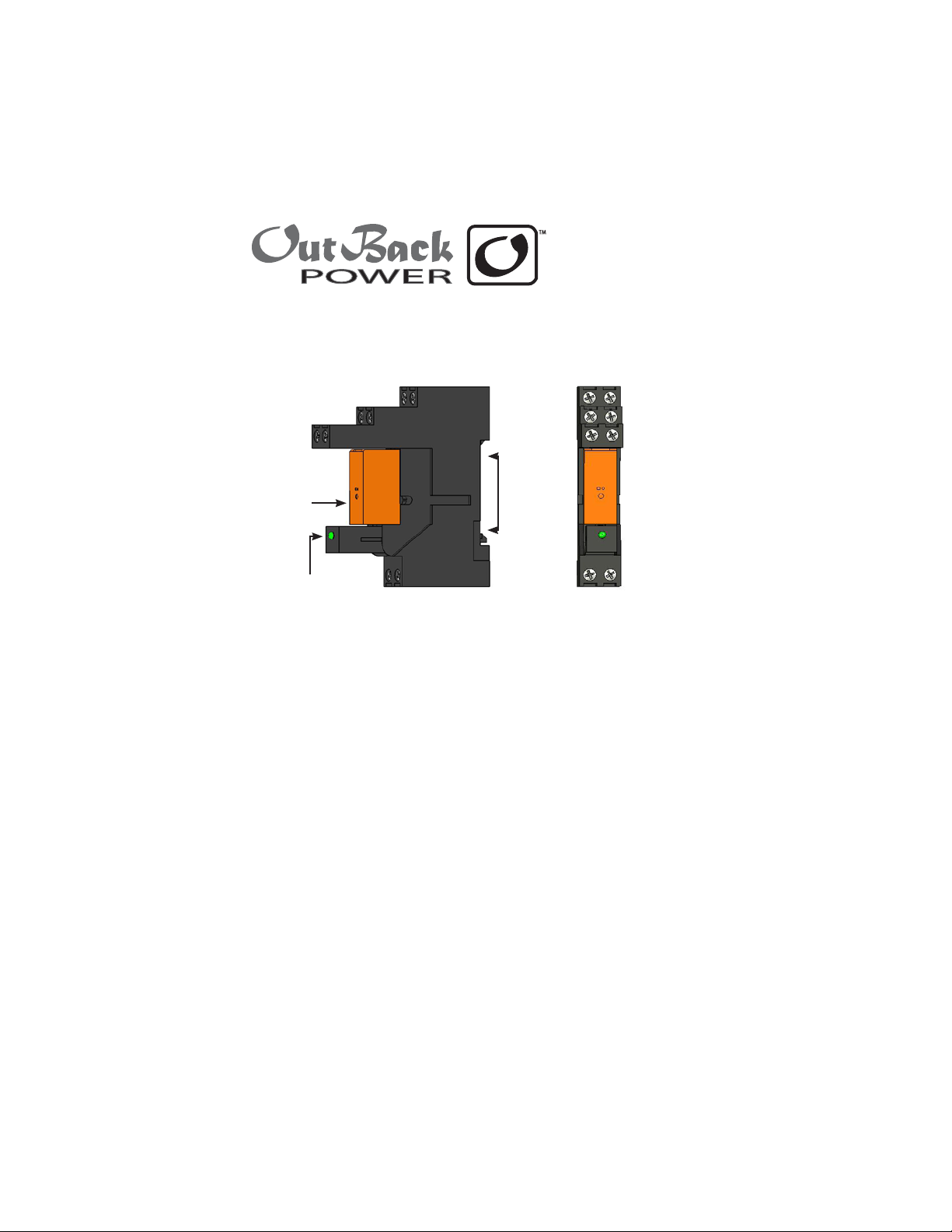
FLEXware16 Amp Maximum 30VDC/250VAC
Rated Relay and DIN Mount Base with LED
RELAY
BASE
LED
The FLEXware Relay Assembly will activate a two-wire start generator
when wired to the AUX output of either an OutBack FX Inverter/Charger
or an OutBack Charge Controller. The assembly consists of an LED
module and a relay inserted (in one orientation) into a base. The base is
mounted onto the DIN rail of any OutBack AC industrial control panel.
SIDE VIEW
FRONT VIEW
Relay Features:
Rated current - 16 amps AC/DC 8 amps per terminal•
Rated voltage - 30VDC/250VAC•
Coil power draw - 400 mW•
Gold contacts for use in low power situations•
A green LED lights to show the relay energizing when proper •
voltage is applied to the relay coil connectors.
Base accommodates connections for wiring the coil, common relay •
contacts, normally open relay contacts, and normally closed relay
contacts.
Page 2
WIRING INSTRUCTIONS
Wire the relay coil from the AUX positive and negative connections of
your OutBack product according to the diagram.
The coil connections (A1 and A2) are not polarity sensitive and the
LED will light in either polarity as long as proper voltage is present.
(Required voltage is nominally 12 VDC, with a minimum of 9 volts.) If
you are unsure, run the AUX positive wire to the A2 terminal and the
AUX negative wire to the A1 terminal, twisting the wires together for a
clean look.
Wire your two-wire gen start connections from the generator to the
normally open and common connections of the relay module. One
wire from the generator will go to the common (COM) connection
and the other wire of the generator will go to the normally open (NO)
connection. The side of the relay base has a schematic of the relay and
its connections.
NOTE: Use proper wire size for the current you intend the relay to
handle and and install a fuse or breaker if necessary.
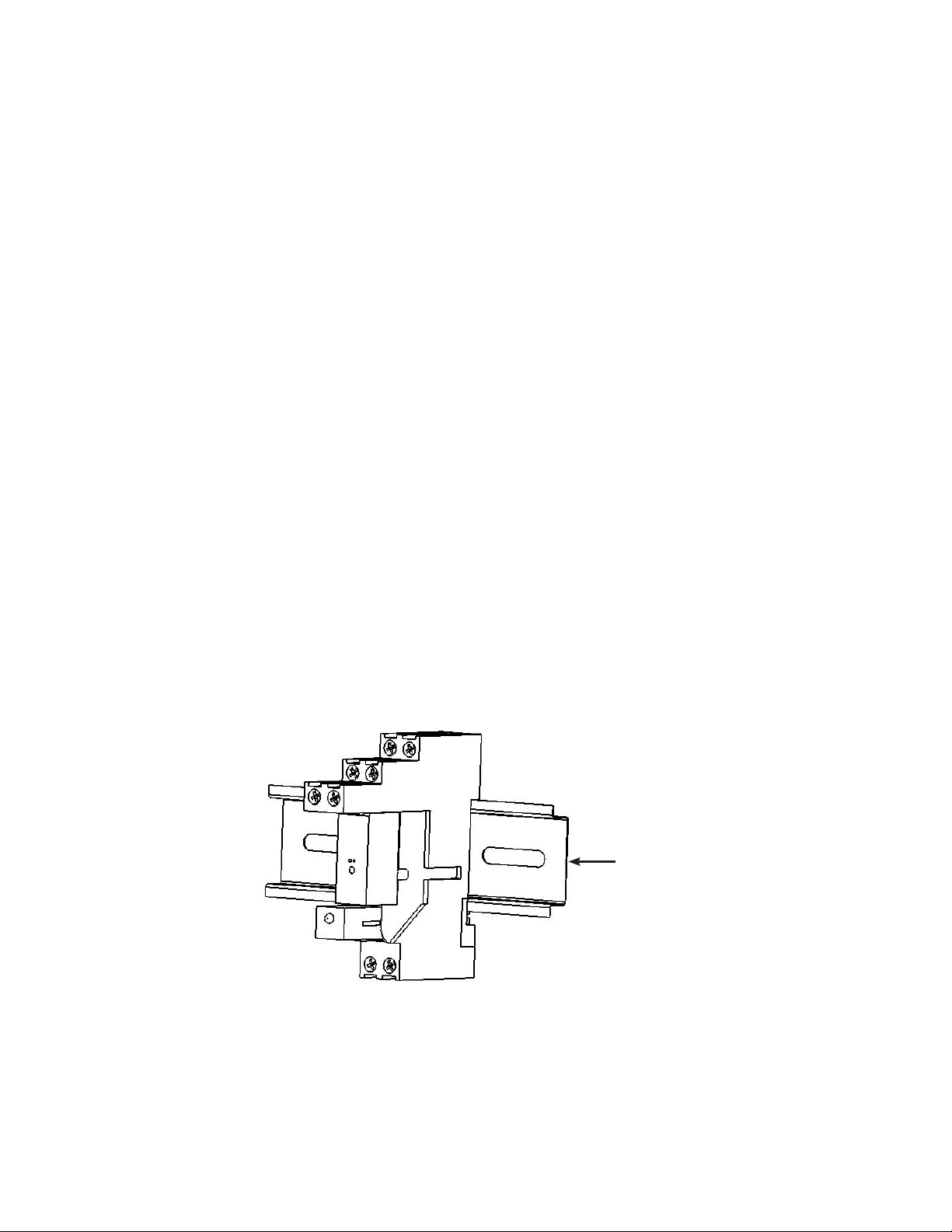
DIN Rail
Page 3

TWO WIRE START
GENERATOR
HOOK UP
GENERATOR
FX INVERTER/CHARGER
NO
NC
INVERTER
ON/OFF
AUX +
AUX -
XCT -
XCT +
COM
12V
RELAY
COIL
There are two screw terminals for each relay contact. Each
can handle up to 8 amps. They are tied together internally.
COM 11 and COM 21 are the common relay connections.
Either can be used for loads under 8 amps. If the load
exceeds 8 amps, use both COM 11 and COM 21.
r NO 14 and NO 24 are normally open relay connections.
Use both 14 and 24 terminals for loads exceeding 8 amps.
r NC 12 and NC 22 are normally closed relay connections.
Use both 12 and 22 terminals for more than 8 amps.
NOTE: If a load exceeds 8 amps, use both screw terminals for any
given relay contact to distribute the current and avoid overloading
the screw terminal.
Terminal screw torque – 0.5 Nm (4.4 inch lbs)
Page 4

Corporate Oce
19009 62nd Avenue NE
Arlington, WA USA
(+1) 360-435-6030
www.outbackpower.com
European Sales Oce
C/ Castelló, 17
08830 - Sant Boi de Llobregat
BARCELONA, España
Phone: +34.93.654.9568
900-0018-01-00 REV A
 Loading...