

Page 1
OS1HardwareUserManual
For Rev C OS1 Sensors
Ouster
Dec01,2020
Page 2

Contents
1 Safetyand SafeUse 3
1.1 Safety& LegalNotices . . . . . . . . . . . . . . . . . . . . . . . . . . . . . . . . . . . . . . . . 3
1.2 ProperAssembly,Maintenanceand SafeUse . . . . . . . . . . . . . . . . . . . . . . . . . . 5
2 OS1Overview 7
3 OS1Product Models 8
4 MechanicalInterface 9
4.1 IncludedComponents . . . . . . . . . . . . . . . . . . . . . . . . . . . . . . . . . . . . . . . . 9
4.2 MountingGuidelines . . . . . . . . . . . . . . . . . . . . . . . . . . . . . . . . . . . . . . . . . 10
4.3 ThermalRequirements . . . . . . . . . . . . . . . . . . . . . . . . . . . . . . . . . . . . . . . . 11
5 ElectricalInterface 12
5.1 Interface Box . . . . . . . . . . . . . . . . . . . . . . . . . . . . . . . . . . . . . . . . . . . . . . 12
5.2 Direct CableConnection and Pinout . . . . . . . . . . . . . . . . . . . . . . . . . . . . . . . . 13
6 DigitalIO 14
6.1 SYNC_PULSE_IN . . . . . . . . . . . . . . . . . . . . . . . . . . . . . . . . . . . . . . . . . . . 14
6.2 MULTIPURPOSE_IO(M_IO) . . . . . . . . . . . . . . . . . . . . . . . . . . . . . . . . . . . . . 15
7 OS1CAD files 17
2
Page 3
1 SafetyandSafeUse
1.1 Safety& LegalNotices
The OS1-128, OS1-64, and OS1-32 have been evaluated to be Class 1 laser products per 60825-1:
2014(Ed. 3)
L’OS1-128,l’OS1-64,et l’OS1-32répondentauxcritèresdesproduitslaser declasse1,selon lanorme
IEC60825-1: 2014(3èmeédition)etémettentdansledomainedel’infrarouge,àunelongueurd’onde
de865nm environ.
FDA21CFR1040 Notice: OS1-128,OS1-64, and OS1-32 comply with FDAperformance standards for
laserproducts except for deviations pursuant to LaserNotice No. 56,dated January19, 2018.
Notice FDA 21CFR1040: L’OS1-128, l’OS1-64, et l’OS1-32 sont conformes aux exigences de perfor-
mances établies par la FDA pour les produits laser, à l’exception des écarts en application de l’avis
nº56,daté du 19janvier 2018.
andoperate in the 865nm band.
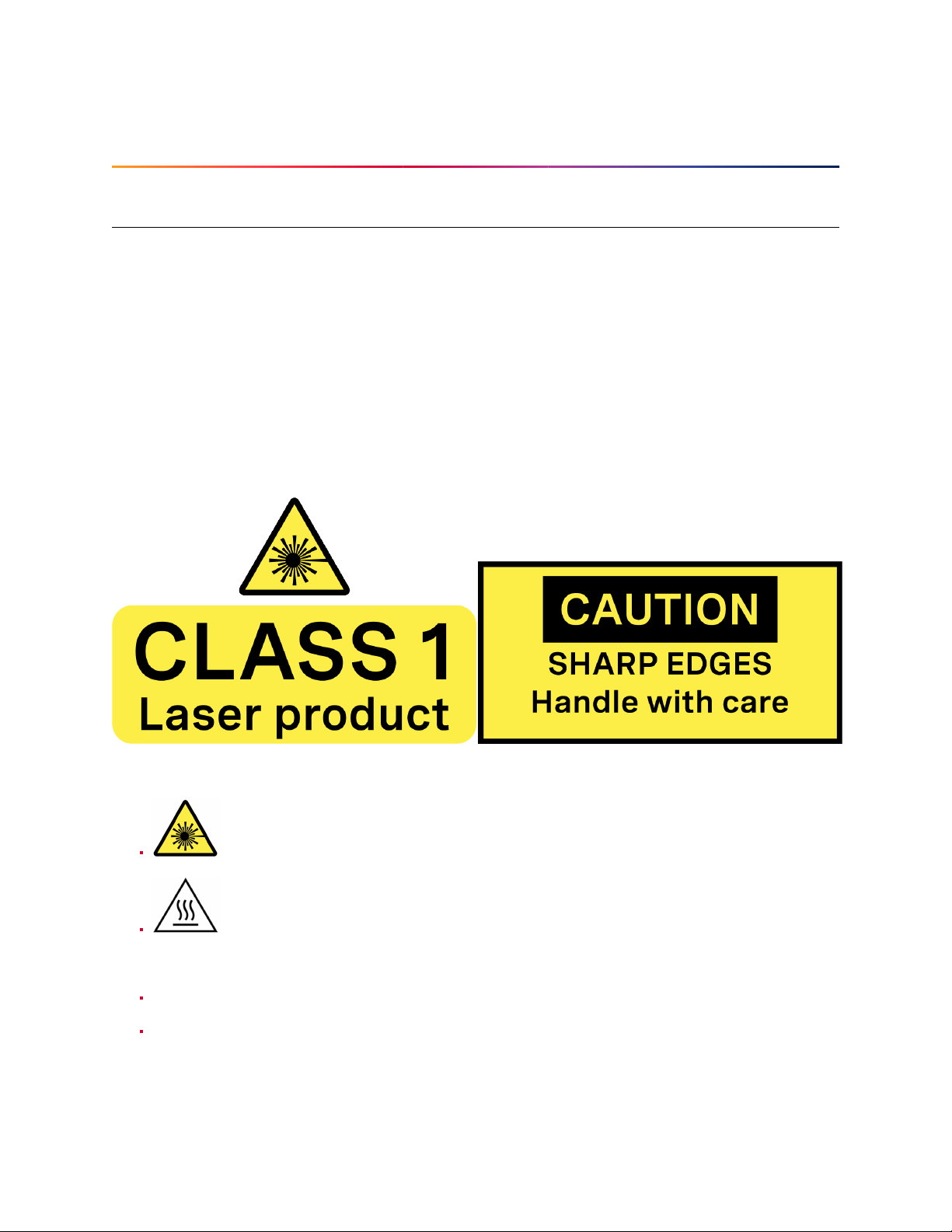
Thefollowingsymbolsappearon theproductlabeland inthemanual andhavethefollowingmeaning.
Thissymbol indicates thatthe sensor emitslaser radiation.
Thissymbol indicates thepresence of ahot surface thatmay cause skinburn.
CAUTIONS:
TheOS1 is ahermetically sealed unit,and is nonuser-serviceable.
Useofcontrols,oradjustments,orperformanceofproceduresotherthanthosespecifiedherein,
mayresult in hazardous radiation exposure.
3
Page 4

Youruseof the OS1 issubject to theTerms ofSale that yousigned with Ousteror your distributor/integrator. Includedin these termsis the prohibitionon:
Removingor otherwise openingthe sensor housing
Inspectingthe internals ofthe sensor
Reverse-engineeringanypartofthe sensor
Permittingany thirdpartytodo anyof the foregoing
Operating the sensor without either the attached mount with which the sensor is shipped, or
attaching the sensor to a surface of appropriate thermal capacity runs the risk of having the
sensoroverheat under certaincircumstances.
This product emits Class 1 invisible laser radiation. The entire window is considered to be the
laseraperture. WhileClass1 lasersare consideredtobe “eyesafe”, avoidprolongeddirectviewingof the laserand do notuse optical instrumentsto viewthe laser.
When operatedin an ambient temperature>40�°C, the metallic surfacesof the sensor may be
hot enough to potentially cause skin burn. Avoid skin contact with the sensor’s base, lid and
heatsinkwhen the sensoris operatedunder these conditions.
PRECAUTIONS:
L’OS1 est une unité hermétiquement scellée, qui ne peut être entretenue ou modifiée par
l’utilisateur.
L’utilisationde commandes, de réglages, ou l’exécutionde procéduresautres que celles spécifiéesdans le présentdocument peuvent entraînerdes rayonnementslaser dangereux.
L’utilisation de l’OS1 est soumise aux conditions de vente signées avec Ouster ou le distributeur/intégrateur,incluantl’interdiction de:
Retirerou ouvrir de quelque façonle boîtier ducapteur
Analyserles composants internes du capteur
Pratiquerla rétro-ingénieriede toute ou partie du capteur
Autoriserune tiercepersonne à menerles actions listéesci-dessus
Ce produit émet un rayonnement laser invisible de classe 1. L’ouverture de sortie du laser est
constituéepar la fenêtredu capteur danssa totalité. Mêmesi les lasersde classe 1ne sont pas
considéréscomme dangereux pourles yeux,ne regardez pasdirectement lerayonnement laser
defaçonprolongée etn’utilisez pasd’instrumentsoptiques pourobserver lerayonnementlaser.
Lors d’une utilisationà température ambiante supérieure à 40°C, la surface métallique du capteur peut présenter des risquesde brûlures pour la peau. Dansces conditions, il est important
d’évitertout contact avecla partie superieure,la baseou le dissipateurthermique du capteur.
EquipmentLabel: Note thattheequipmentlabel, whichincludesmodel andserialnumber andnotice
thatthe unitis aClass 1LaserProduct, isaffixed tothe undersideof theSensorEnclosure Baseitself.
It is onlyvisible after the attached mount with whichthe Sensor is shipped, is removed. Please refer
4
Page 5

tolocation details inthe Mechanical Interface section.
L’étiquettedel’équipement,comprenantlemodèle, lenumérodesérie,etlaclassificationduproduit
laser (ici, classe 1), est apposéeau dessousde labase du boîtierdu capteur. Il n’estvisible qu’après
avoirretiré le diffuseur de chaleur aveclequel le capteur est expédié. L’emplacementest décrit avec
précisiondans la section«Mechanical Interface».
Electromagnetic Compatibility: TheOS1 is an FCC 47 CfR 15 SubpartB device. This device complies
with part 15 of the FCC Rules. Operation is subject to the following conditions: (1) This device may
not cause harmful interference, and (2) this device must accept any interferencereceived, including
interferencethat maycause undesired operation.
“Ouster” and “OS1” are both registered trademarks of Ouster, Inc. They may not be used without
expresspermission from Ouster, Inc.
Ifyou haveany questions about the abovepoints, contact usat [email protected].
1.2 ProperAssembly,Maintenance andSafeUse
TheOS1maybeeasilysetupbymountingtothebasetoamountingwiththecorrectmountingholepattern,and followingtheinterconnection instructionsdelineated inMounting Guidelines. Any mounting
orientationisacceptable. Eachsensorisshippedattached toamountfortestor normalusespecified
operatingtemperaturerange, butthe sensormay bemounted directlytoany appropriatemount with
Thermal Capacity appropriate for the application of the user. Please contact Ouster for assistance
withapproving the use of user specificmounting arrangements.
Any attempt to utilize the sensor outside the Environmental parameters delineated in the OS1 data
sheetmay result in voiding ofthe warranty.
When power is applied, the sensor powers up and commences boot-up with the laser disabled. The
bootup sequence isapproximately 60s in duration, after which the internalsensor optics subassembly commences spinning, and the laser is activated, and the unit operates in the default 1024 x 10
Hz mode. When the sensor is running, and the laser is operating, a faint red flickering light may be
seenbehind the optical window. Note thatthe OS1 utilizes an865nm infrared laserthat is only dimly
discernableto thenakedeye, whiletransmitting alaser eye-safefundamental signalin the865nm IR
band. While thesensor isfully Class1 eyesafe, Ousterstrongly recommendsagainstpeering intothe
opticalwindowat closerangewhile thesensoris operating. TheOS1 isahermetically sealedunit, and
isnot user-serviceable. Any attemptto unsealthe enclosurehas thepotentialto exposethe operator
tohazardous laser radiation.
Ouster sensors are equipped with amulti-layer series of internal safety interlocks to ensure complianceto Class 1Laser Eye Safelimits.
TheSensoruserinterfacemaybeusedconfigurethesensortoanumberofcombinationsofscanrates
andresolutions otherthan thedefaultvalues of1024 x10 Hzresolution. Inallavailable combinations,
the unit has been evaluated by an NRTL to remain within the classification of aClass 1 LaserDevice
asper IEC 60825-1:2014(Ed. 3).
5
Page 6

Assemblagecorrect et utilisation sûre
L’OS1 s’installefacilement en fixant la base surun supportpercé detrous concordants, et en suivant
les instructions d’interconnexiondécrites dans la section «Mounting Guidelines». Toute orientation
demontageest acceptable. Chaquecapteur estexpédiééquipéd’un dissipateurdechaleur,utilisable
en phase de test et en conditions normales. Néanmoins toutautre support présentant une capacité
thermiqueappropriéepourl’applicationdel’utilisateurpeutêtreutilisé. VeuillezcontacterOusterdans
lecas où unmontage spécifique àvotre application seraitnécessaire.
Toutetentative d’utilisation du capteur en dehors des paramètres environnementaux définis dans la
fichetechnique de l’OS1peut entraînerl’annulationde la garantie.
Lorsquelecapteurestsous tension,celui-cidémarreet commencesoninitialisationavecle laserdésactivé. Letempsdedémarrageestd’environ60s,aprèsquoilesous-systèmeoptiqueentreenrotation
etlelaserestactivé, lecapteuropèrealorsdanssonmodepar défautde1024x10Hz. Lorsquelecapteur est en marche et que le laser est active, on peut apercevoirune faible lumière rouge vacillante
derrièrela vitre teintée. L’OS1utilise une longueurd’ondes infra-rouge de 865nm nmà peine perceptible pour l’œil humain, et le rayonnement laser IR émis est sans danger pour les yeux. Cependant,
bienqueles rayonnementslaserde classe1soient sansdangerdans desconditions raisonnablement
prévisibles,Ousterrecommandefortementdene pasregarderfixementla vitreteintéependantquele
capteurest en marche. L’OS1est une unitéhermétiquement scellée, quine peut pas êtreentretenue,
modifiée ou réparéepar l’utilisateur. Toute tentative d’ouverture du boîtier a pour risque d’exposer
l’opérateurà un rayonnementlaser dangereux.
L’OS1 est une unité hermétiquement scellée, qui ne peut pas être entretenue, modifiée ou réparée.
Toutetentatived’ouvertureduboîtiera pourrisqued’exposerl’opérateuràun rayonnementlaser dangereux.
LescapteursOustersontéquipés d’unesériede dispositifsdesécuritéà plusieursniveaux,defaçon à
assureren toutescirconstances le respectdes limites d’irradiancecorrespondant aux rayonnements
lasersde classe 1,sans danger pourles yeux.
L’interfaceutilisateur du logicieldu capteurpeut êtreutilisée pour configurerle capteurselon uncertainnombredecombinaisonsdevitessesdebalayageetderésolutionsautresquelesvaleursutilisées
pardéfaut, respectivementde 1024 x10 Hz.
6
Page 7

2 OS1Overview
The OS1 offers an industry-leading combination of price, performance, reliability, size, weight, and
power. Itis designed for indoor/outdoorall-weather environmentsand long lifetime. As the smallest
high performance lidar on the market, the OS1 can be directly integrated into vehicle facias, robots,
anddrones.
The OS1 family of sensors consist of three models, the OS1-128, OS1-64, and OS1-32, with differing
resolution,but of identicalmechanical dimensions.
HIGHLIGHTS
Fixedresolution per frameoperating mode
Camera-gradeintensity,near-infrared, andrange data
Multi-sensorcrosstalk immunity
Simultaneousand co-calibrated 2D and 3D output
Industryleading intrinsic calibration
Exampleclient code available
For the purposes of this documwent, the term “OS1” refers to the family of sensors, and only where
thereis a differencein performancewill each modelbe referredto byits specific modeldesignation.
7
Page 8

3 OS1ProductModels
TheOS1isavailablewith 128,64,or32beams ofverticalresolutionandwith Uniform,Gradient,Above
Horizon,or Below Horizonbeam spacing options. Productspecs andmore informationon these configurationscan be foundon theOS1 product page.
8
Page 9

4 MechanicalInterface
4.1 IncludedComponents
TheOS1 isshipped withthe followingitems:
OS1-128,OS1-64, or OS1-32
Sensorto interface boxcable/connector
InterfaceBox and 24VAC/DCpower supply(2 meters)
RJ45cable (1 meter)
Optional: Heat sink
DownloadableCAD files forthe OS1can be foundonline at www.ouster.com/lidar-product-details
Warning: Water ingress protection: The sensor ingress protection rating is only valid if the I/O
cable is plugged intothe panel mount connector on the base of the sensor, and the locking collet
rotated past the detent click to the properly locked condition i.e past the détente position. The
9
Page 10

cable and plug arean element of the sensor ingress protectionsystem. Without this the ingress
protection rating may be compromised. Bending the cable at a sharp angle directly after egress
from the plug overmold should also be avoided. Sharp bends and high axial stresses on the cable immediately adjacent to the plug over mold may create a moisture ingress path into the the
connector. Please notethe cable minimumbend radius requirementsbelow:
I/OCable type O.D. CableMinimum BendRadius
FixedBend FlexingBend
OusterThick Cable 10.5mm 79mm (7.5*OD) 158mm (15*OD)
OusterThin Cable (Standard) 8mm 50mm(5*OD) 80mm(10*OD)
4.2 MountingGuidelines
Oursensorsship withmodular mountingoptions. Propermountingwill ensureoptimalsensor performance,reducing noise fromvibration andproviding efficient heatdissipation.
Mount to a materialwith high thermal conductivity. The following are recommendedaluminum
alloysand their thermalconductivity:
1) 6061: 167 W/m-K
2) 7075: 130W/m-K
3) 2024: 121W/m-K
Ensureinterfaces areclean and freefrom debris
Torqueboltsappropriately forthe mount materialand bolts
UseTIM (Thermal InterfaceMaterial) forany irregularor unmachined surfaces
Donot overconstrainthe sensor ifmounting to boththe topand the bottom
Usea thermally conductivepad to ensuregood conductivitywhile not overconstraining.
Ensure your implementation maintains the base and top of the sensorat no greaterthan 25ºC
aboveambient with an ambient less than50ºC
Theshapeofanyheatsinkshouldmaximizethesurfaceareaforfreeandforcedconvectionwhile
beingthick enough toallow the heatto conductthrough the material
If you have questions about your specific mounting situation please contact the Ouster at sup-
10
Page 11

4.3 ThermalRequirements
Thermal requirements specific to Rev C OS1 are listed below. Please contact [email protected] or
withyour sensor serialnumber if youdo not knowwhat Revyour sensoris.
Table4.1: Thermal requirementsforOS1 with modularcap
MaxTempbefore shot limiting
Tempthat shot limiting saturates
Max Temp before sensor
mayshut off
Requirements
Chassis
Temp(ºC)
52 47
60 55
65 60
ExampleTestCase
Convective Air Temp with Radial Heatsink and
StandardBase (ºC)
11
Page 12
5 ElectricalInterface
5.1 InterfaceBox
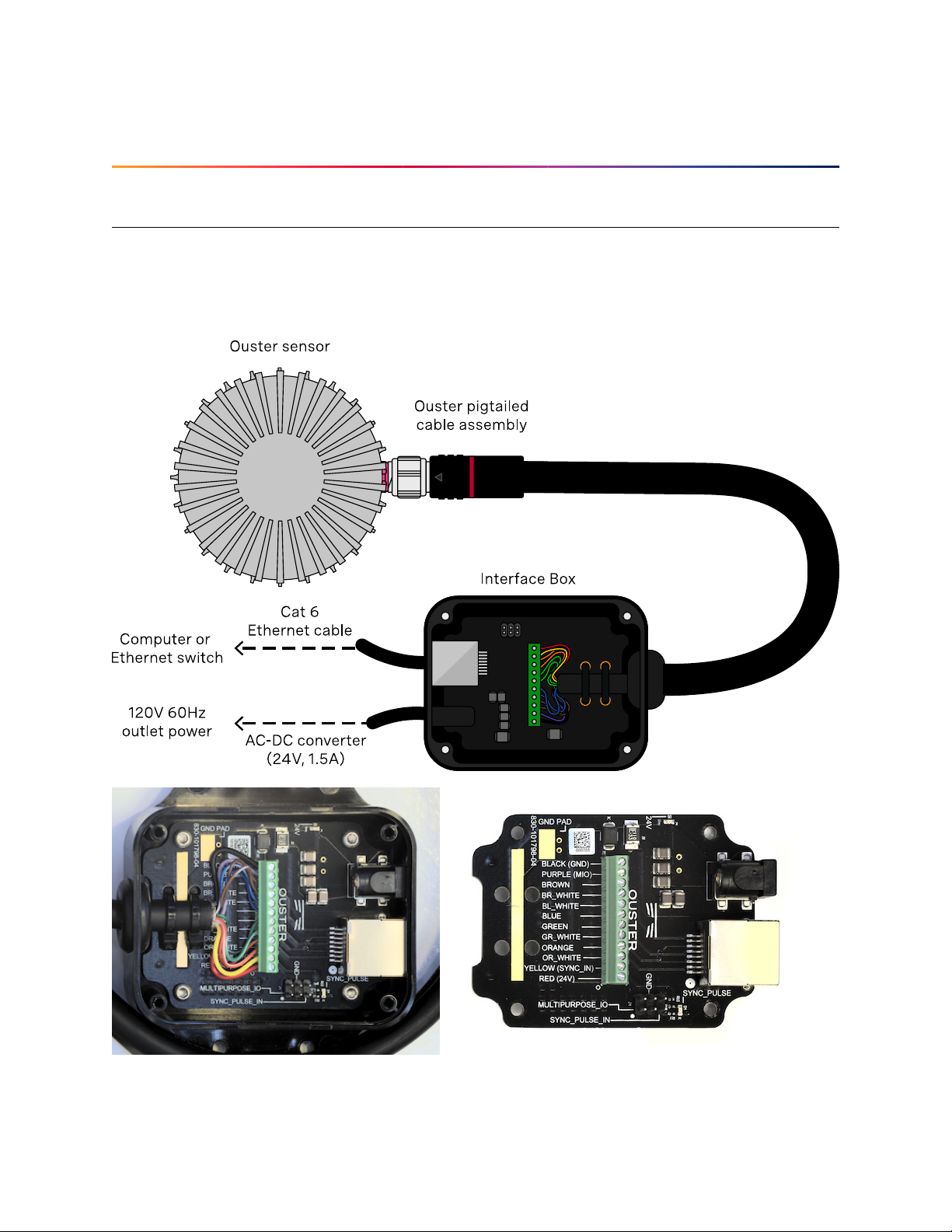
The Interface Box that accompanies the OS1 is designed to allow the sensor tobe operatedfor test
and evaluation purposes. It terminates the interface cable from the sensor, allows it to be powered
up and provides access to the sensor gigabit Ethernet Interface via astandard RJ45 connector. DC
Powerto thesensor is providedto theInterface Box bythe accompanying24V DC supply.
12
Page 13
5.2 DirectCableConnection and Pinout
TheOS1 can beoperated without theuse of anInterface Box.
Warning: Ouster is not responsiblefor any errorsin wiring as a resultof bypassing the Interface
Box andthis activity may result in a voidingof your warranty if itresults in damage to the sensor.
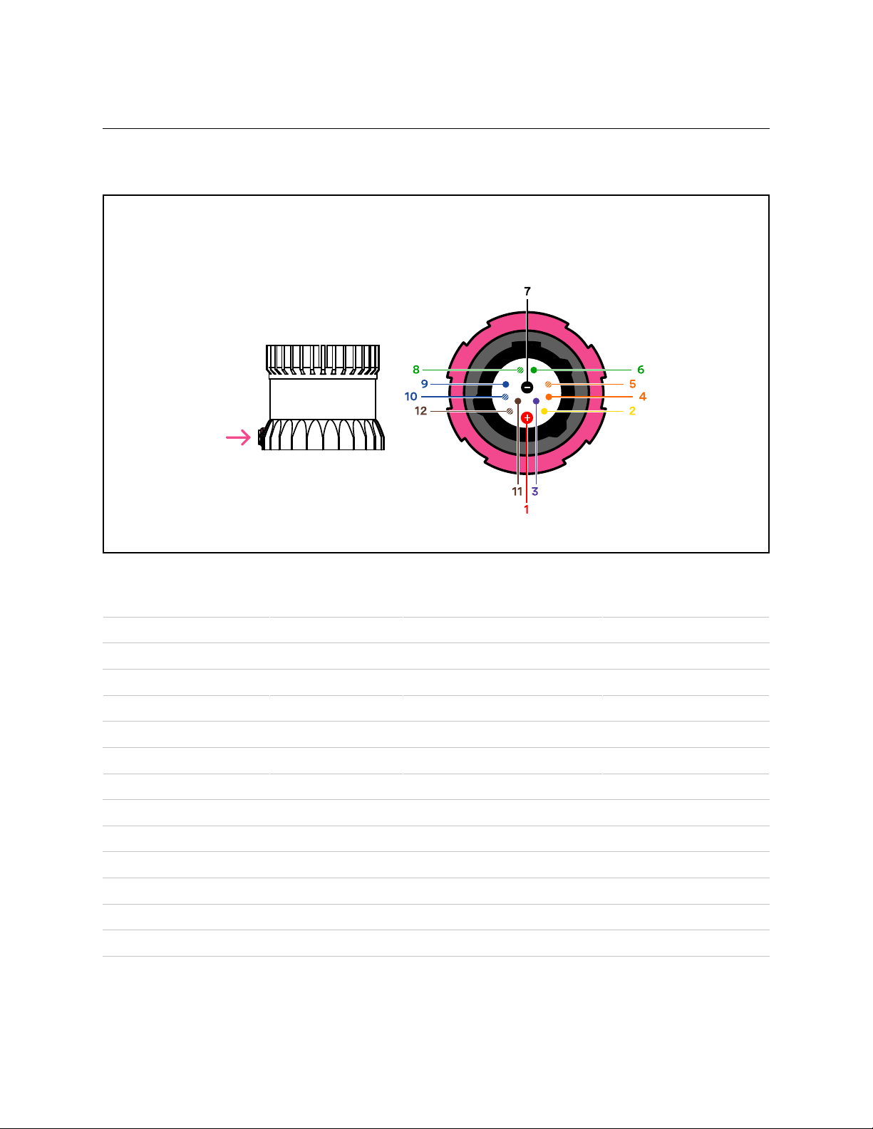
The followingguidelines for direct cable connection assume use of the Ouster-provided 24V 1.5A
powersupply. Ouster cannotbe held responsiblefor damage tothe deviceif alternateis used
Figure5.1: cable pinoutof on-sensor receptacle
Table5.1: Ouster Cable Pinout: Connector,Sensor P/Ns: 840_101855,840_102144,840_102145, 840_102146
NetName PinNumber Wire TwistedWith
MULTIPURPOSE_IO 3 Purple,26 AWG N/A
SYNC_PULSE_IN 2 Yellow, 26AWG N/A
VCC_24 1 Red,22 AWG N/A
GROUND 7 Black,22 AWG N/A
TRP_1_P(Ethernet) 5 White/Orange,26AWG Orange
TRP_1_N(Ethernet) 4 Orange,26 AWG White/Orange
TRP_2_P(Ethernet) 8 White/Green,26 AWG Green
TRP_2_N(Ethernet) 6 Green, 26AWG White/Green
TRP_3_P(Ethernet) 9 Blue,26 AWG White/Blue
TRP_3_N(Ethernet) 10 White/Blue,26 AWG Blue
TRP_4_P(Ethernet) 12 White/Brown,26 AWG Brown
TRP_4_N(Ethernet) 11 Brown,26 AWG White/Brown
13
Page 14

6 DigitalIO
6.1 SYNC_PULSE_IN
SYNC_PULSE_IN is adedicatedinput channelthat isaccessible withinthe InterfaceBox JumperJ4. This
channel expects an input pulse sequence which can be used fortime synchronization. See the Software UserManual for more information on configuring this input. Any referencesto pulse polarity in
thisdocumentreferencesthesignalpolarityontheSYNC_PULSE_IN pin ofthesensor. Thisinputchannel
isprotected byan optoisolator which will draw10mA at fullturn on.
Table6.1: SYNC_PULSE_INInterfaceRequirements
Parameter MinVoltage MaxVoltage MinDriver Current
LOGICLOW 0V 1V N/A
LOGICHIGH 3.3V 15V 5mA
SYNC_PULSE_IN Interface Requirements were tested with 2 m cable Interface Box connection at 2
MHz.
When GPIO has 5 mA drive strength minimum, GPIO can be directly connected to the
SYNC_PULSE_IN pinoftheinterfaceboxheader. Thisisthemostcommoncaseandhasbeentested
to work on common Arduino microcontroller series. Typical common logic levels of 3.3 V, 5 V
GPIOof microcontrollerscan produce drivestrength of5 mA min(Arduino, MSP430, etc.).
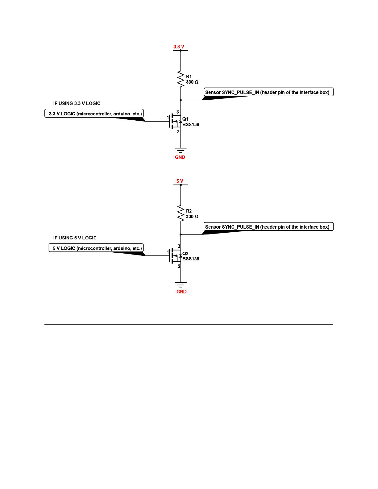
If the 5 mA drive strength minimum cannot be met, a buffer circuit is required to drive
SYNC_PULSE_IN.Example circuits are provided for common 3.3V and5 V logic.
14
Page 15
6.2 MULTIPURPOSE_IO(M_IO)
MULTIPURPOSE_IO (M_IO) is a configurable input or output channel accessible within the Interface Box
JumperJ4connectedtotheMULTIPURPOSE_IOpinoftheInterfaceBox. Detailedinformationonhow
toconfigurethischannelusingthe sensorTCPinterfacecanbefoundinthe APIGuide. By defaultthis
channelis disabled.
When this channel is configured as an OUTPUT, the M_IO sends a pulse sequence that can be used
fortimesynchronization or event triggering outside the sensor. For a full description of output pulse
triggeringoptions,seetheSoftwareUserManualsection. Thisoutputisanoptoisolatedopencollector
circuit, relying on an externallyprovided pull-up resistor. This resistor is not provided as part of the
InterfaceBox.
15
Page 16

Table6.2: MULTIPURPOSE_IO - OUTPUTInterface Requirements
Parameter Min Max
PullUp Voltage N/A 15V
SinkingCurrent N/A 25 mA
When this channel is configured as an INPUT, the M_IO can accept a standard NMEA $GPRMC UART
message. These messages are a common way for GPS systems to share timestamp information in
UTCtime format. More information on this packetstructure and supported baud rates can be found
inthe Time Synchronizationsection of the Software UserManual.
Table6.3: MULTIPURPOSE_IO- INPUT InterfaceRequirements
Parameter MinVoltage MaxVoltage MinDriver Current
LOGICLOW 0V 1V N/A
LOGICHIGH 1.7 V 15V 10mA
Above are tested with 2 m cable interface box connection at 2 MHz.
16
Page 17

7 OS1CAD files
Allthe most up-to-dateCAD files ofour productscan be foundon ourLidar Product Detailspage.
17
 Loading...