

Page 1

SoftwareUserManual
Firmware v2.0.0 for all Ouster sensors
Ouster
Jan15,2021
Page 2

Contents
1 SafetyandSafeUse 5
1.1 Safety& LegalNotices . . . . . . . . . . . . . . . . . . . . . . . . . . . . . . . . . . . . . . . . 5
1.2 ProperAssembly,Maintenanceand SafeUse . . . . . . . . . . . . . . . . . . . . . . . . . . 7
1.2.1 Assemblagecorrectet utilisation sûre . . . . . . . . . . . . . . . . . . . . . . . . . . 8
2 Connectingto Sensor 9
2.1 Network Configuration . . . . . . . . . . . . . . . . . . . . . . . . . . . . . . . . . . . . . . . . 9
2.2 SensorOutputVisualization . . . . . . . . . . . . . . . . . . . . . . . . . . . . . . . . . . . . . 10
3 SensorData 11
3.1 CoordinateFrames and XYZ Calculation . . . . . . . . . . . . . . . . . . . . . . . . . . . . . 11
3.1.1 LidarCoordinateFrame . . . . . . . . . . . . . . . . . . . . . . . . . . . . . . . . . . . 11
3.1.2 Lidar Range toXYZ . . . . . . . . . . . . . . . . . . . . . . . . . . . . . . . . . . . . . . 12
3.1.3 Sensor CoordinateFrame . . . . . . . . . . . . . . . . . . . . . . . . . . . . . . . . . . 13
3.1.4 CombiningLidar and SensorCoordinateFrame . . . . . . . . . . . . . . . . . . . . . 14
3.1.5 Lidar IntrinsicBeamAngles . . . . . . . . . . . . . . . . . . . . . . . . . . . . . . . . . 14
3.1.6 LidarRange Data ToSensor XYZ Coordinate Frame . . . . . . . . . . . . . . . . . . 14
3.1.7 IMUData ToSensor XYZ CoordinateFrame . . . . . . . . . . . . . . . . . . . . . . . 15
3.2 Lidar Data . . . . . . . . . . . . . . . . . . . . . . . . . . . . . . . . . . . . . . . . . . . . . . . 16
3.2.1 Lidar Data Format . . . . . . . . . . . . . . . . . . . . . . . . . . . . . . . . . . . . . . 16
3.2.2 Lidar Data PacketSizeCalculation . . . . . . . . . . . . . . . . . . . . . . . . . . . . . 18
3.3 IMU Data . . . . . . . . . . . . . . . . . . . . . . . . . . . . . . . . . . . . . . . . . . . . . . . . 18
3.3.1 IMU DataFormat . . . . . . . . . . . . . . . . . . . . . . . . . . . . . . . . . . . . . . . 18
3.4 DataRates . . . . . . . . . . . . . . . . . . . . . . . . . . . . . . . . . . . . . . . . . . . . . . . 19
3.5 Range Performanceby Lidar Mode . . . . . . . . . . . . . . . . . . . . . . . . . . . . . . . . 20
4 Key Features 21
4.1 AzimuthWindow . . . . . . . . . . . . . . . . . . . . . . . . . . . . . . . . . . . . . . . . . . . 21
4.1.1 Expected SensorBehavior. . . . . . . . . . . . . . . . . . . . . . . . . . . . . . . . . . 22
4.1.2 AzimuthWindowExamples . . . . . . . . . . . . . . . . . . . . . . . . . . . . . . . . . 22
4.2 PhaseLock . . . . . . . . . . . . . . . . . . . . . . . . . . . . . . . . . . . . . . . . . . . . . . . 22
4.2.1 PhaseLockingReferenceFrame . . . . . . . . . . . . . . . . . . . . . . . . . . . . . . 23
4.2.2 PhaseLockingCommands . . . . . . . . . . . . . . . . . . . . . . . . . . . . . . . . . 23
4.2.3 Multi-sensorExample . . . . . . . . . . . . . . . . . . . . . . . . . . . . . . . . . . . . 24
4.2.4 Accuracy . . . . . . . . . . . . . . . . . . . . . . . . . . . . . . . . . . . . . . . . . . . . 25
4.2.5 PhaseLocking Alerts . . . . . . . . . . . . . . . . . . . . . . . . . . . . . . . . . . . . . 25
4.3 StandbyOperating Mode . . . . . . . . . . . . . . . . . . . . . . . . . . . . . . . . . . . . . . 26
4.3.1 ExpectedSensor Behavior. . . . . . . . . . . . . . . . . . . . . . . . . . . . . . . . . . 26
4.3.2 StandbyOperating Mode Examples . . . . . . . . . . . . . . . . . . . . . . . . . . . . 26
4.4 Cold Start . . . . . . . . . . . . . . . . . . . . . . . . . . . . . . . . . . . . . . . . . . . . . . . 27
4.4.1 HardwareRequirements . . . . . . . . . . . . . . . . . . . . . . . . . . . . . . . . . . . 27
4.4.2 Cold Start Operation . . . . . . . . . . . . . . . . . . . . . . . . . . . . . . . . . . . . . 27
4.4.3 Indications and Alerts . . . . . . . . . . . . . . . . . . . . . . . . . . . . . . . . . . . . 28
5 TimeSynchronization 29
5.1 Timing Overview Diagram . . . . . . . . . . . . . . . . . . . . . . . . . . . . . . . . . . . . . . 29
5.2 Sensor Time Source . . . . . . . . . . . . . . . . . . . . . . . . . . . . . . . . . . . . . . . . . 30
5.2.1 Setting Ouster Sensor Time Source . . . . . . . . . . . . . . . . . . . . . . . . . . . . 30
2
Page 3

5.2.2 External TriggerClock Source . . . . . . . . . . . . . . . . . . . . . . . . . . . . . . . 32
5.3 NMEA Message Format . . . . . . . . . . . . . . . . . . . . . . . . . . . . . . . . . . . . . . . 33
6 Inputs and Interfaces 35
6.1 WebInterface . . . . . . . . . . . . . . . . . . . . . . . . . . . . . . . . . . . . . . . . . . . . . 36
6.2 ElectricalandMechanical Interface . . . . . . . . . . . . . . . . . . . . . . . . . . . . . . . . 37
7 Troubleshooting 38
7.1 SensorHomepageandHTTPServer . . . . . . . . . . . . . . . . . . . . . . . . . . . . . . . . 38
7.2 Networking . . . . . . . . . . . . . . . . . . . . . . . . . . . . . . . . . . . . . . . . . . . . . . . 38
7.3 get_alerts . . . . . . . . . . . . . . . . . . . . . . . . . . . . . . . . . . . . . . . . . . . . . . . 38
7.4 Using Latest Firmware . . . . . . . . . . . . . . . . . . . . . . . . . . . . . . . . . . . . . . . . 40
8 HTTP API Reference 41
8.1 system/firmware . . . . . . . . . . . . . . . . . . . . . . . . . . . . . . . . . . . . . . . . . . . . 41
8.1.1 GET/api/v1/system/firmware . . . . . . . . . . . . . . . . . . . . . . . . . . . . . . . 41
8.2 diagnostics . . . . . . . . . . . . . . . . . . . . . . . . . . . . . . . . . . . . . . . . . . . . . . . 41
8.2.1 GET /api/v1/diagnostics/dump . . . . . . . . . . . . . . . . . . . . . . . . . . . . . . . 41
8.3 system/network . . . . . . . . . . . . . . . . . . . . . . . . . . . . . . . . . . . . . . . . . . . . . 42
8.3.1 GET /api/v1/system/network . . . . . . . . . . . . . . . . . . . . . . . . . . . . . . . . 42
8.3.2 GET /api/v1/system/network/ipv4 . . . . . . . . . . . . . . . . . . . . . . . . . . . . 43
8.3.3 GET /api/v1/system/network/ipv4/override . . . . . . . . . . . . . . . . . . . . . . . 43
8.3.4 PUT/api/v1/system/network/ipv4/override . . . . . . . . . . . . . . . . . . . . . . . 44
8.3.5 DELETE /api/v1/system/network/ipv4/override. . . . . . . . . . . . . . . . . . . . . 44
8.4 time . . . . . . . . . . . . . . . . . . . . . . . . . . . . . . . . . . . . . . . . . . . . . . . . . . . 45
8.4.1 GET/api/v1/time . . . . . . . . . . . . . . . . . . . . . . . . . . . . . . . . . . . . . . . 45
8.4.2 GET/api/v1/time/system . . . . . . . . . . . . . . . . . . . . . . . . . . . . . . . . . . 47
8.4.3 GET/api/v1/time/ptp . . . . . . . . . . . . . . . . . . . . . . . . . . . . . . . . . . . . 49
8.4.4 GET /api/v1/time/sensor . . . . . . . . . . . . . . . . . . . . . . . . . . . . . . . . . . 51
9 TCP API 53
9.1 QueryingSensor Info andIntrinsicCalibration . . . . . . . . . . . . . . . . . . . . . . . . . . 53
9.2 Querying Activeor Staged Parameters . . . . . . . . . . . . . . . . . . . . . . . . . . . . . . 59
9.3 SettingConfigurationParameters . . . . . . . . . . . . . . . . . . . . . . . . . . . . . . . . . 63
10 APIChangelog 68
11 Alerts and Errors 72
11.1 TableofAllAlertsand Errors . . . . . . . . . . . . . . . . . . . . . . . . . . . . . . . . . . . . 72
12 LidarPacket Format Update 78
13 CrosstalkMitigation Tutorial 80
13.1 Two Sensor Example . . . . . . . . . . . . . . . . . . . . . . . . . . . . . . . . . . . . . . . . . 80
14 Drivers 83
14.1 OpenSource Drivers . . . . . . . . . . . . . . . . . . . . . . . . . . . . . . . . . . . . . . . . . 83
14.2 Ouster Studio . . . . . . . . . . . . . . . . . . . . . . . . . . . . . . . . . . . . . . . . . . . . . 83
15 PTPQuickstart Guide 84
15.1 Assumptions . . . . . . . . . . . . . . . . . . . . . . . . . . . . . . . . . . . . . . . . . . . . . . 84
15.2 PhysicalNetworkSetup . . . . . . . . . . . . . . . . . . . . . . . . . . . . . . . . . . . . . . . 84
15.2.1 Third Party GrandmasterClock . . . . . . . . . . . . . . . . . . . . . . . . . . . . . . 84
3
Page 4

15.2.2 LinuxPTP GrandmasterClock . . . . . . . . . . . . . . . . . . . . . . . . . . . . . . . 85
15.3 ExampleNetworkSetup . . . . . . . . . . . . . . . . . . . . . . . . . . . . . . . . . . . . . . . 86
15.4 Installing Necessary Packages . . . . . . . . . . . . . . . . . . . . . . . . . . . . . . . . . . . 86
15.5 EthernetHardwareTimestamp Verification . . . . . . . . . . . . . . . . . . . . . . . . . . . 87
15.6 Configurations. . . . . . . . . . . . . . . . . . . . . . . . . . . . . . . . . . . . . . . . . . . . . 88
15.6.1 Configuring ptp4l forMultiple Ports . . . . . . . . . . . . . . . . . . . . . . . . . . . . 88
15.6.2 Configuringptp4l as a Local MasterClock . . . . . . . . . . . . . . . . . . . . . . . . 90
15.6.3 Configuringphc2sys to Synchronize theSystem Time to thePTPClock . . . . . . . 90
15.6.4 Configuring ChronytoSet SystemClockUsing PTP . . . . . . . . . . . . . . . . . . 91
15.7 VerifyingOperation . . . . . . . . . . . . . . . . . . . . . . . . . . . . . . . . . . . . . . . . . . 93
15.7.1 HTTP API . . . . . . . . . . . . . . . . . . . . . . . . . . . . . . . . . . . . . . . . . . . . 93
15.7.2 LinuxPTP PMC Tool . . . . . . . . . . . . . . . . . . . . . . . . . . . . . . . . . . . . . . 93
15.7.3 Tested GrandmasterClocks . . . . . . . . . . . . . . . . . . . . . . . . . . . . . . . . . 94
16 NetworkingGuide 95
16.1 Networking101 . . . . . . . . . . . . . . . . . . . . . . . . . . . . . . . . . . . . . . . . . . . . 95
16.2 Windows . . . . . . . . . . . . . . . . . . . . . . . . . . . . . . . . . . . . . . . . . . . . . . . . 96
16.2.1 ConnectingtheSensor . . . . . . . . . . . . . . . . . . . . . . . . . . . . . . . . . . . 96
16.2.2 The SensorHomepage . . . . . . . . . . . . . . . . . . . . . . . . . . . . . . . . . . . . 96
16.2.3 DeterminingtheIPv4 Address oftheSensor . . . . . . . . . . . . . . . . . . . . . . . 97
16.2.4 Determining the IPv4Addressof the Interface . . . . . . . . . . . . . . . . . . . . . 98
16.2.5 SettingtheHost Interface to DHCP . . . . . . . . . . . . . . . . . . . . . . . . . . . . 98
16.2.6 Settingthe Host Interface toStatic IP . . . . . . . . . . . . . . . . . . . . . . . . . . . 99
16.2.7 Finding aSensor with mDNS Service Discovery . . . . . . . . . . . . . . . . . . . . . 99
16.3 macOS . . . . . . . . . . . . . . . . . . . . . . . . . . . . . . . . . . . . . . . . . . . . . . . . . 101
16.3.1 Connecting the Sensor . . . . . . . . . . . . . . . . . . . . . . . . . . . . . . . . . . . 101
16.3.2 The SensorHomepage . . . . . . . . . . . . . . . . . . . . . . . . . . . . . . . . . . . . 101
16.3.3 Determiningthe IPv4 Address ofthe Sensor . . . . . . . . . . . . . . . . . . . . . . . 101
16.3.4 Determining the IPv4Addressof the Interface . . . . . . . . . . . . . . . . . . . . .102
16.3.5 SettingtheHost Interface toDHCP . . . . . . . . . . . . . . . . . . . . . . . . . . . . 103
16.3.6 Settingthe Host Interface toStatic IP . . . . . . . . . . . . . . . . . . . . . . . . . . . 104
16.3.7 FindingaSensor with mDNS Service Discovery . . . . . . . . . . . . . . . . . . . . . 104
16.4 Linux . . . . . . . . . . . . . . . . . . . . . . . . . . . . . . . . . . . . . . . . . . . . . . . . . . 106
16.4.1 Connectingthe Sensor . . . . . . . . . . . . . . . . . . . . . . . . . . . . . . . . . . . 106
16.4.2 Setting the InterfacetoLink-Local Only . . . . . . . . . . . . . . . . . . . . . . . . . .106
16.4.3 The Sensor Homepage . . . . . . . . . . . . . . . . . . . . . . . . . . . . . . . . . . . .107
16.4.4Determiningthe IPv4 Addressof the Sensor . . . . . . . . . . . . . . . . . . . . . . .108
16.4.5 Determining the IPv4Addressof the Interface . . . . . . . . . . . . . . . . . . . . .109
16.4.6 Setting theHostInterface to DHCP . . . . . . . . . . . . . . . . . . . . . . . . . . . . 110
16.4.7 Setting the HostInterfaceto Static IP . . . . . . . . . . . . . . . . . . . . . . . . . . . 111
16.4.8 Finding a SensorwithmDNS Service Discovery . . . . . . . . . . . . . . . . . . . . . 113
17 UpdatingFirmware 114
17.1 DowngradingFirmware . . . . . . . . . . . . . . . . . . . . . . . . . . . . . . . . . . . . . . . 114
18 Firmware Changelog 115
4
Page 5
1 SafetyandSafeUse
1.1 Safety&LegalNotices
AllOuster sensorshavebeenevaluatedto beClass 1 laser products per 60825-1: 2014 (Ed. 3) and
operatein either the850nmor 865nm band.
Tousles capteursOuster répondentaux critères des produits laser de classe 1, selon la norme IEC
60825-1: 2014 (3ème édition) et émettent dans le domaine de l’infrarouge, à une longueur d’onde
deXXXXXXXXX environ.
FDA21CFR1040 Notice: All Ouster sensors complywithFDA performance standardsfor laser productsexcept fordeviationspursuant to LaserNotice No. 56, dated January 19,2018.
Notice FDA 21CFR1040: Tous les capteurs Ouster sont conformes aux exigences de performances
établiesparlaFDA pour les produits laser,à l’exceptiondesécartsen application de l’avisnº56, daté
du19 janvier 2018.
Thefollowingsymbolsappearontheproductlabel andinthemanualandhavethefollowingmeaning.
Thissymbol indicates that thesensoremits laser radiation.
Thissymbol indicates the presenceof a hot surface thatmaycause skin burn.
CAUTIONS:
AllOuster sensors arehermetically sealed units, andarenot user-serviceable.
Useofcontrols,oradjustments,orperformanceofproceduresotherthanthosespecifiedherein,
mayresult in hazardousradiation exposure.
5
Page 6

YouruseofanyOustersensorissubjecttothe TermsofSalethat yousignedwith Ousteroryour
distributor/integrator. Includedinthese terms is theprohibitionon:
Removingor otherwise opening thesensorhousing
Inspectingthe internals of thesensor
Reverse-engineeringanypartofthe sensor
Permittingany thirdpartytodo any oftheforegoing
Operating the sensor without either the attached mount with which the sensor is shipped, or
attaching the sensor to a surface of appropriate thermal capacity runs the risk of having the
sensoroverheat under certain circumstances.
This product emits Class 1 invisible laser radiation. The entire window is considered to be the
laseraperture. WhileClass1 lasersare consideredtobe“eyesafe”,avoidprolongeddirectviewingof the laser and donot use optical instrumentstoview the laser.
Whenoperatedin an ambient temperature >40�°C, the metallic surfaces of the sensor may be
hot enough to potentially cause skin burn. Avoid skin contact with the sensor’s base, lid and
heatsinkwhen the sensor isoperatedunder these conditions.
PRECAUTIONS:
Tous les capteurs Ouster sont des unités hermétiquement scellées, qui ne peuvent être entretenuesou modifiées parl’utilisateur.
L’utilisationde commandes, de réglages, ou l’exécution de procédures autres que celles spécifiéesdans le présent documentpeuvententraîner des rayonnementslaser dangereux.
L’utilisationd’un capteur Ouster est soumise aux conditions de vente signées avecOusterou le
distributeur/intégrateur,incluantl’interdiction de:
Retirerou ouvrir dequelquefaçon le boîtier ducapteur
Analyserles composants internesdu capteur
Pratiquerla rétro-ingénieriedetoute ou partie ducapteur
Autoriserune tiercepersonneà mener les actionslistéesci-dessus
L’utilisationdu capteur sans sondissipateur thermique fourni lors de la livraison ou une utilisation qui ne maintiendrait pas un contact suffisant avec une surface aux propriétés thermiques
adéquates, présentent toutes deux un risque de surchauffe du capteur dans certaines circonstances.
Ce produit émet un rayonnement laser invisible de classe 1. L’ouverture de sortie du laser est
constituéepar la fenêtre ducapteurdans sa totalité. Même si les lasersde classe 1 ne sont pas
considéréscomme dangereux pourlesyeux, ne regardezpasdirectement le rayonnementlaser
defaçonprolongéeetn’utilisez pasd’instruments optiquespour observerle rayonnementlaser.
Lorsd’une utilisation à température ambiante supérieure à 40°C, la surface métallique du capteur peut présenter des risques de brûlures pour la peau. Dansces conditions, il est important
6
Page 7

d’évitertout contact avecla partie superieure, labaseou le dissipateur thermiqueducapteur.
EquipmentLabel: Notethattheequipment label,which includesmodeland serialnumberandnotice
thatthe unitis aClass 1LaserProduct,isaffixed tothe undersideof theSensorEnclosureBaseitself.
It is only visible after the attached mount withwhich the Sensor is shipped, is removed. Please refer
tolocation details in theMountingsection of the HardwareUser Manual.
L’étiquettedel’équipement,comprenantlemodèle,lenumérodesérie,etlaclassificationduproduit
laser (ici, classe 1), est apposée au dessous de la base du boîtier du capteur. Il n’estvisible qu’après
avoirretiré le diffuseur dechaleur aveclequel lecapteurest expédié. L’emplacement est décritavec
précisiondansleManuel d’UtilisateurHardware(HardwareUserManual), danslasection«Mounting»
ElectromagneticCompatibility: YourOustersensoris anFCC 47CfR15Subpart Bdevice. Thisdevice
complies with part 15 of the FCC Rules. Operation is subject to the following conditions: (1) This
devicemaynotcauseharmfulinterference,and(2) thisdevicemustacceptanyinterferencereceived,
includinginterference that maycause undesired operation.
“Ouster”,“OS0”,“OS1”, and “OS2” areallregisteredtrademarks of Ouster,Inc. They may not be used
withoutexpress permission fromOuster,Inc.
Ifyou haveany questions about theabovepoints, please contact[email protected].
1.2 ProperAssembly,Maintenanceand SafeUse
AllOustersensorsmaybeeasilysetupbymountingtothebasetoamountingwiththecorrectmounting hole pattern and following the interconnection instructions delineated in the Mounting section
of the Hardware User Manual. Any mounting orientation is acceptable. Each sensor is shipped attachedtoa mount for test or normal use specified operating temperaturerange,but thesensor may
bemounted directly to anyappropriatemount with Thermal Capacity appropriateforthe application
of the user. Please contact Ouster for assistance with approving the use of user specific mounting
arrangements.
Any attempt to utilize the sensor outside the Environmental parameters delineated in the relevant
datasheet for yourOuster sensor mayresultin voiding ofthewarranty.
When power is applied, the sensor powers up and commences boot-up with the laser disabled. The
bootupsequenceisapproximately60sinduration,afterwhichtheinternalsensoropticssubassembly
commencesspinning,andthelaserisactivated,andtheunitoperatesinthedefault1024x10Hzmode.
Whenthe sensor is running, and the laserisoperating,a faint red flickeringlight may be seen behind
theoptical window. Note thattheallOuster sensors utilize eitheran850nm or 865 nm infraredlaser
thatisonlydimlydiscernabletothe nakedeye,whiletransmittingalasereye-safefundamental signal
in the respective IR band. Refer to the appropriate Hardware User Manual to determine the specific
wavelength of your sensor. While the sensor is fully Class 1 eye safe, Ouster strongly recommends
againstpeeringintotheopticalwindowatcloserangewhilethesensorisoperating. AllOustersensors
arehermetically sealed units, and are not user-serviceable. Any attempttounseal the enclosure has
thepotential to exposetheoperator tohazardouslaser radiation.
Ouster sensors are equipped with a multi-layer series of internal safety interlocks to ensure complianceto Class 1 LaserEyeSafe limits.
TheSensoruserinterfacemaybeusedconfigurethesensortoanumberofcombinationsofscanrates
7
Page 8

andresolutionsotherthan thedefault valuesof1024x10 Hzresolution. In allavailablecombinations,
the unit has been evaluated by an NRTLto remain within the classification of a Class 1 Laser Device
asper IEC 60825-1:2014 (Ed. 3).
1.2.1 Assemblagecorrect et utilisation sûre
TouslescapteursOusters’installentfacilementenfixantlabasesurunsupportpercédetrousconcordantsetensuivant lesinstructions d’interconnexiondécrites leManuel d’UtilisateurHardware (HardwareUserManual). Touteorientationdemontageestacceptable. Chaquecapteurestexpédiééquipé
d’un dissipateur de chaleur, utilisable en phase de test et en conditions normales. Néanmoins tout
autre support présentant une capacité thermique appropriée pour l’application de l’utilisateur peut
êtreutilisé. Veuillezcontacter Ouster dansle cas où unmontagespécifique à votreapplication serait
nécessaire.
Toutetentative d’utilisation du capteur en dehors des paramètresenvironnementauxdéfinis dans la
fichetechnique de votrecapteur Ouster peutentraînerl’annulationde la garantie.
Lorsquelecapteurestsous tension,celui-cidémarreetcommencesoninitialisationaveclelaserdésactivé. Letempsdedémarrageestd’environ60s,aprèsquoilesous-systèmeoptiqueentreenrotation
etlelaserestactivé, lecapteuropèrealorsdansson modepardéfautde1024x10Hz. Lorsquelecapteur est en marche et que le laser est active, on peut apercevoir une faible lumière rouge vacillante
derrièrela vitreteintée. Tous les capteurs Ouster utilisent des longueurs d’ondesinfra-rouge de 850
ou865nmàpeineperceptiblepourl’œilhumain,etlerayonnementlaserIRémisestsansdangerpour
les yeux. Lalongueur d’ondespécifique de votre capteur est disponible dans le Manuel d’Utilisateur
Hardware (Hardware User Manual). Cependant, bien que les rayonnements laser de classe 1 soient
sans danger dans des conditions raisonnablement prévisibles, Ouster recommande fortement de ne
pasregarderfixementlavitreteintéependantquelecapteurestenmarche. TouslescapteursOuster
sontdesunitéshermétiquement scellées,quine peuventpasêtreentretenues,modifiéesouréparées
parl’utilisateur. Toutetentatived’ouverturedu boîtier a pour risque d’exposerl’opérateuràun rayonnementlaser dangereux.
LescapteursOustersontéquipésd’unesérie dedispositifsdesécuritéàplusieursniveaux,defaçonà
assureren toutes circonstancesle respect des limitesd’irradiancecorrespondant aux rayonnements
lasersde classe 1, sansdangerpour les yeux.
L’interfaceutilisateurdu logicielducapteur peutêtreutilisée pour configurerle capteurselonun certainnombredecombinaisonsdevitessesdebalayageetderésolutionsautresquelesvaleursutilisées
pardéfaut, respectivementde1024 x 10 Hz.
8
Page 9
2 ConnectingtoSensor
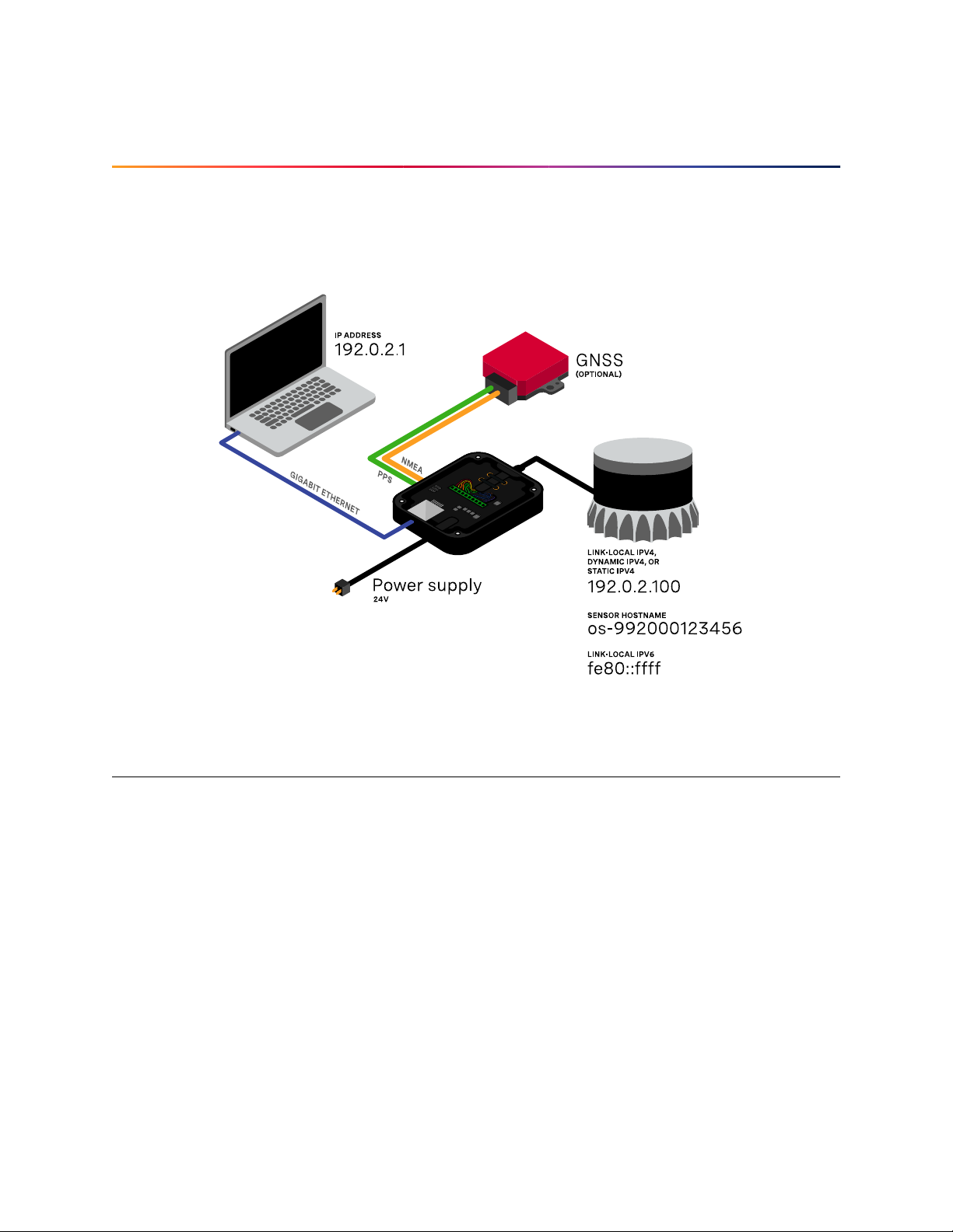
YourOustersensorrequiresacomputerwitha gigabitEthernetconnection anda24Vsupply. Optionally you may time synchronize the sensor through an external time source or through the computer
viaPTP.
2.1 NetworkConfiguration
The sensor is designed to communicate with a host machine through a variety of different methods
sucha DHCP,IPv6/IPv4 link-local, and staticIP.
On most systems you should be able to connect the sensor into your network or directly to a host
machineand simple use the senorhostname to communicate withit.
Thesensor hostname is, os-991234567890.local,where991234567890 is the sensorserialnumber.
Formoredetailedguidanceon communicatingwiththe sensoronvarious operatingsystemsandnet-
worksettings please referencethe Networking Guide in the Appendix.
CommandsforsettinganddeletingastaticIPaddresscanbefoundintheHTTPAPIReferencesection.
9
Page 10

2.2 SensorOutput Visualization
Afterconnectingtoyoursensor,youcanquicklyvisualizethepointcloudthrougheitherOusterStudio
orwithoursampledrivers. BothOusterStudioandoursampledriversareavailableforLinux,Mac,and
Windows. Please visit www.ouster.com/resourcesforthe latest toolstovisualize yoursensoroutput.
10
Page 11

3 SensorData
3.1 Coordinate Frames and XYZCalculation
Ousterdefines twocoordinateframes: The Lidar Coordinate Frame follows the Right Hand Rule convention and is a point cloud-centric
frameof referencethat is the simplest frame in which to calculate and manipulate point clouds. The
X-axispoints backwards towardstheexternalconnector,which is an unintuitive orientation that was
deliberatelychosen tomeetthe following criteria:
dataframes split at thebackof the sensor i.e. theexternalconnector
dataframes start with the azimuthangleequal to 0°
AllpointcloudfeaturesincludingsettinganazimuthwindowandphaselockingaredefinedintheLidar
CoordinateFrame.
TheSensor CoordinateFrame followstheRight Hand Ruleconventionandisa mechanical housingcentric frame of reference that follows robotics convention with X-axis pointing forward. Ousterprovideddriversandvisualizers representdatain the Sensor CoordinateFrame.
Note: All Ouster coordinate frames follow the Right Hand Rule, allowing for standard 3D transformationmatrix math to convertbetweenthem. For multi-sensor systemsthat require calibration, this
Linear Algebra-based approach can be convenient. However, customerswith single-sensor systems
mayfind it moreintuitiveto stayinthe Lidar CoordinateFrameand take arithmeticshortcuts.
3.1.1 Lidar Coordinate Frame
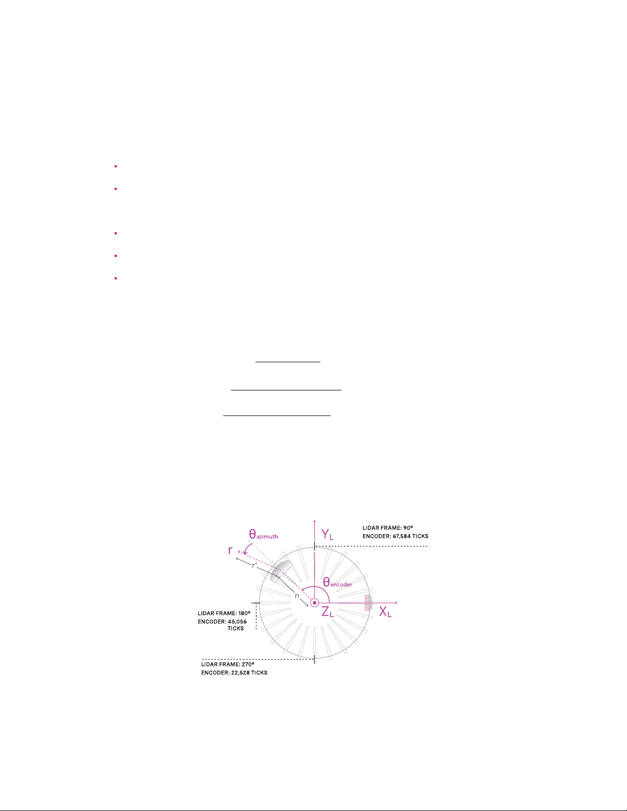
The Lidar Coordinate Frame is defined at the intersection of the lidar axis of rotation and the lidar
optical midplane (a plane parallel to Sensor Coordinate Frame XY plane and coincident with the 0°
elevationbeam angle of thesensor).
TheLidar CoordinateFrame axesare arrangedwith:
positiveX-axispointedat encoder angle 0°and the external connector
positiveY-axispointed towardsencoder angle 90°
positiveZ-axis pointedtowards the topof the sensor
TheLidar Coordinate Frameis marked in bothdiagrams below with XL,YL,and ZL.
11
Page 12
3.1.2 Lidar Range to XYZ
Giventhefollowinginformation,range datamay betransformedinto3DcartesianXYZ coordinatesin
theLidar Coordinate Frame:
Froma measurementblock fromthe UDPpacket:
encoder_count of the measurement block
range_mm value of the data blockof the i-th channel
Fromthe get_beam_intrinsics TCP command:
lidar_origin_to_beam_origin_mm value
beam_altitude_angles array
beam_azimuth_angles array
Thecorresponding 3D point canbecomputed by
r = range_mm
n = lidar_origin_to_beam_origin_mm
θ
encoder
θ
azimuth
= 2π ·(1 −
= −2π
ϕ = 2π
beam_altitude_angles[i]
encoder_count
90112
beam_azimuth_angles[i]
360
360
)
x = (r − n) cos(θ
= (
y
r−n
)
sin
(
encoder
θ
encoder
+ θ
+
azimuth
θ
azimuth
) cos(ϕ) + n cos(θ
)
cos
(ϕ) +
sin
n
(
encoder
θ
encoder
)
)
z = (r − n) sin(ϕ)
FiguresFig. 3.1and Fig.3.2 show,respectively,a top-down andside view of thesensor.
Figure3.1: Top-downview of LidarCoordinate Frame
12
Page 13
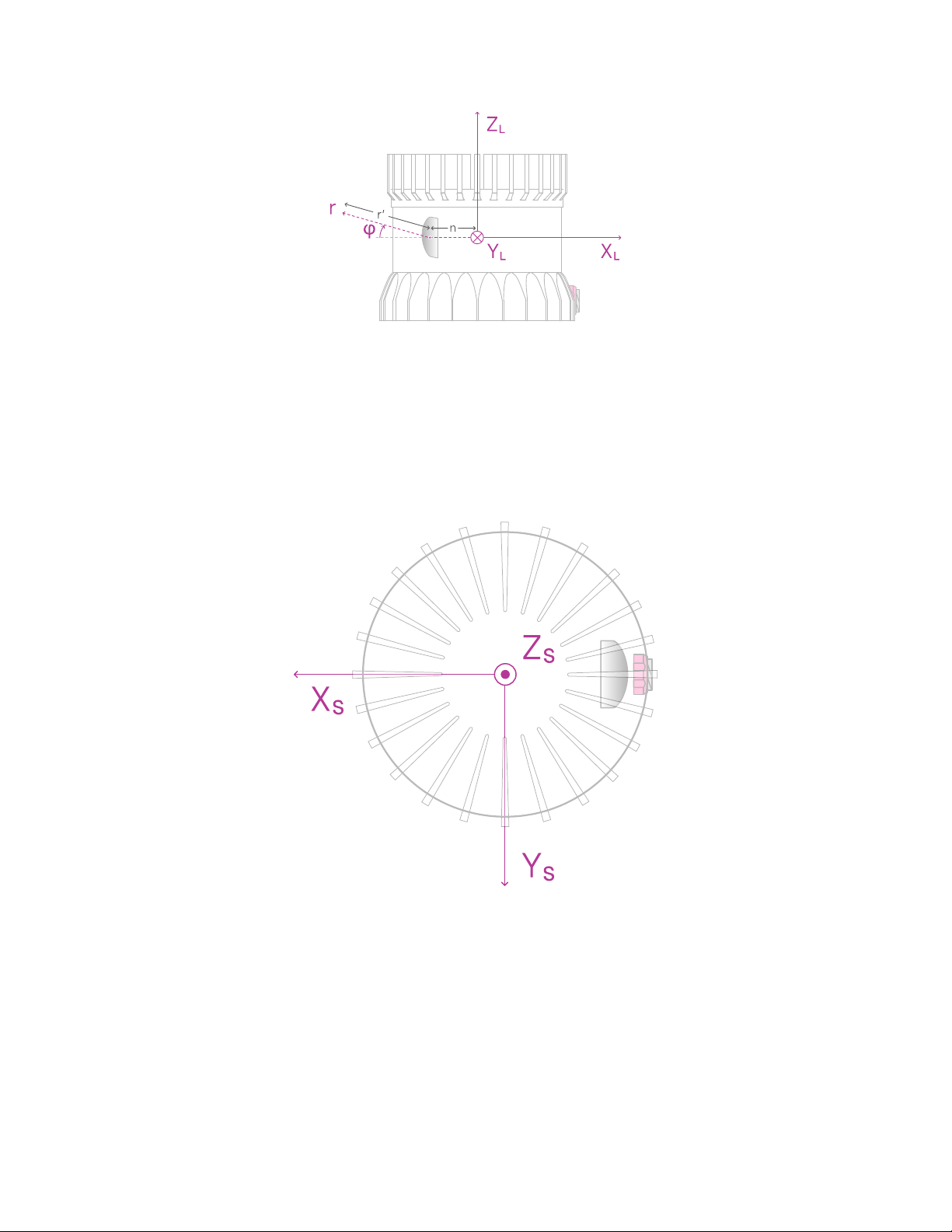
Figure3.2: Sideview ofLidar Coordinate Frame
3.1.3 SensorCoordinate Frame
The Sensor Coordinate Frame is defined at the center of the sensor housing on the bottom, with the
X-axispointedforward,Y-axispointedtotheleftandZ-axispointedtowardsthetopofthesensor. The
external connector is located in the negative x direction. The Sensor Coordinate Frame is marked in
thediagram below withXS,YS,ZS.
Figure3.3: Top-downviewof Sensor CoordinateFrame
13
Page 14
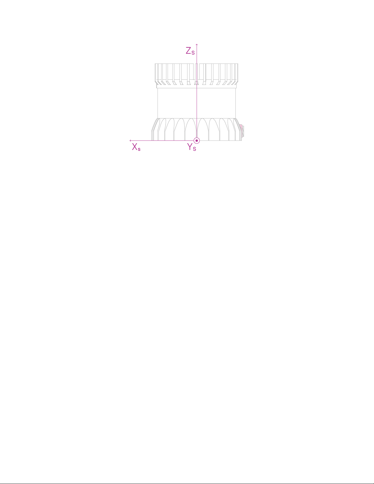
Figure3.4: Sideview ofSensor Coordinate Frame
3.1.4 Combining Lidar and SensorCoordinate Frame
The Lidar Coordinate Frame’s positive X-axis (0 encoder value) is opposite the Sensor Coordinate
Frame’s positive X-axis to center lidar data about the Sensor Coordinate Frame’s positive X-axis. A
single measurement frame starts at the Lidar Coordinate Frame’s 0° position and ends at the 360°
position. This is convenient when viewing a “range image” of the Ouster Sensor measurements, allowing the “range image” to be centered in the Sensor Coordinate Frame’s positive X-axis, which is
generallyforward facingin most robotic systems.
The Ouster Sensor scans in the clockwise direction when viewed from the top, which is a negative
rotationalvelocityaboutthe Z-axis. Thus, asencoderticksincreasesfrom0to90,111,theactual angle
aboutthe Z-axis intheLidar Coordinate Framewill decrease.
3.1.5 Lidar Intrinsic Beam Angles
The intrinsic beam angles for each beam may be queried with a TCP command get_beam_intrinsics
to provide an azimuth and elevation adjustmen offset to the each beam. Theazimuth adjustment is
referencedoff of the current encoder angle and the elevation adjustment is referenced from the XY
planein the Sensor and LidarCoordinate Frames.
3.1.6 LidarRange Data To SensorXYZ CoordinateFrame
Forapplicationsthatrequirecalibration againstaprecision mountoruse theIMUdataincombination
withthelidar data, the XYZ points should be adjusted to the SensorCoordinateFrame. Thisrequires
aZtranslation andarotationofthe X,Y,Zpointsaboutthe Z-axis. Theztranslationistheheight ofthe
lidaraperturestopabovethesensororigin, whichis variesdependingon thesensoryouhave,andthe
datamust berotated180°aroundthe Z-axis. This informationcan be queriedover TCPintheformof
ahomogeneous transformationmatrixin row-major ordering.
ExampleJSON formattedqueryusingthe TCPcommandget_lidar_intrinsics:
14
Page 15

{
"lidar_to_sensor_transform": [-1, 0, 0, 0, 0, -1, 0, 0, 0, 0, 1, 36.180, 0, 0, 0, 1]
}
Whichcorresponds to thefollowingmatrix
M_lidar_to_sensor =
−1 0 0 0
0 −1 0 0
0 0 1 36.180
0 0 0 1
The table below lists all product lines’ distances of the aperture stop above the sensor origin for use
inthe z translation.
ProductLine Lidar aperture stopabove sensor origin
OS0 36.180mm
OS1 36.180mm
OS2 74.296mm
3.1.7 IMU Data To SensorXYZ CoordinateFrame
TheIMUis slightly offsetin the Sensor Coordinate Frameforpractical reasons. The IMU origin in the
Sensor Coordinate Frame can be queried over TCP in the form of an homogeneous transformation
matrixin row-major ordering.
ExampleJSON formattedqueryusingthe TCPcommandget_imu_intrinsics:
{
"imu_to_sensor_transform": [1, 0, 0, 6.253, 0, 1, 0, -11.775, 0, 0, 1, 7.645, 0, 0, 0, 1]
}
Whichcorresponds to thefollowingmatrix
M_imu_to_sensor =
1 0 0 6.253
0 1 0 −11.775
0 0 1 7.645
0 0 0 1
15
Page 16

3.2 LidarData
3.2.1 Lidar Data Format
Note: Gen1OS1-16andOS1-32customersshould notethatupgradingtofirmwarev2.0.0willchange
theirlidar packet formatwhich reduces their datarateswhich is notbackwardscompatible with prev2.0.0clients. Pleaserefer to the Lidar Packet Format Update section for more information on this
change.
Lidardata packetsconsist of16Measurement Blocksand vary insizerelativetothe numberofchannels in the sensor. The packet rate is dependent on the lidar mode. Words are 32 bits in length and
littleendian. By default, lidarUDPdata is forwarded toPort 7502.
Lidar frames are composed of 512, 1024, or 2048 measurement blocks, depending upon lidar mode
andarecompletely deterministic in number per frame and their monotonic order and position within
lidardata packets. Thisdeterminismallows forefficientlookup table-based decodinginclients.
EachMeasurement Block contains:
HeaderBlock [128 bits]
Timestamp [64bit unsigned int]-timestamp of the measurementinnanoseconds.
MeasurementID[16bitunsignedint]-asequentiallyincrementingmeasurementcounting
upfrom 0 to511,or 0 to1023, or 0 to2047 dependingonlidar_mode.
Frame ID [16 bit unsigned int] - index of the lidar scan. Incrementsevery time the sensor
completesa rotation, crossingthe zero point oftheencoder.
Encoder Count [32 bit unsigned int] - an azimuth angle as a raw encoder count, starting
from0withamaxvalueof90,111-incrementing44tickseveryazimuthanglein2048mode,
88ticksin1024mode,and176ticksin512mode. Note: theencodercountisredundantwith
theMeasurement ID and willbedeprecated in thefuture.
NChannel Data Blocks [96bits each]
Range [32 bit unsigned int - only 20 bits used] - range in millimeters, discretized to the
nearest3 millimeters.
SignalPhotons[16bitunsignedint]-signalintensityphotonsinthesignalreturnmeasure-
mentare reported.
Reflectivity [16 bit unsigned int] - sensor Signal Photons measurements are scaled based
on measured range and sensor sensitivity at that range, providing an indication of target
reflectivity.Calibrationofthismeasurementhasnotcurrentlybeenrigorouslyimplemented,
butthis will be updatedina future firmwarerelease.
NearInfraredPhotons[16 bitunsigned int]- NIRphotons relatedtonatural environmental
illuminationare reported.
MeasurementBlockStatus [32bits]-indicateswhetherthe measurementblock containsvalid
16
Page 17
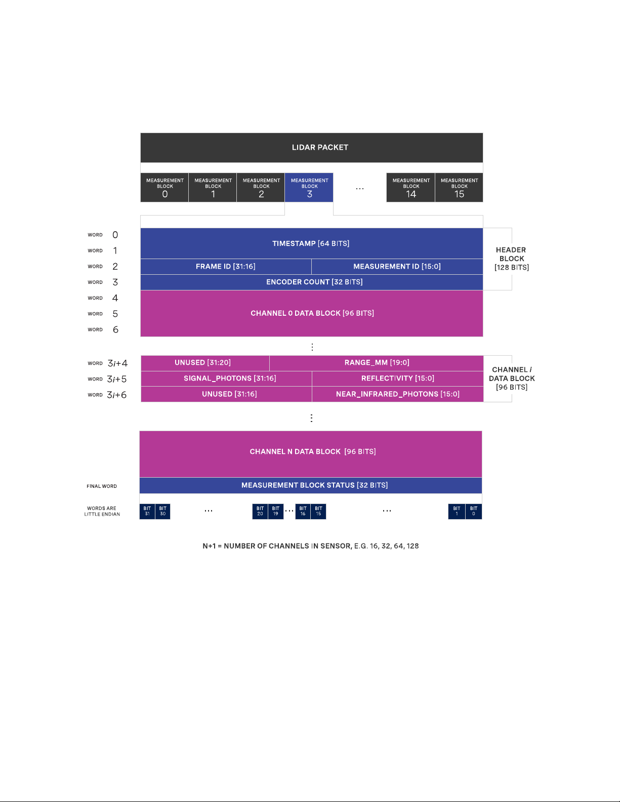
or zero-padded data in its channels’ Data Blocks. Valid = 0xFFFFFFFF, Padded = 0x0. If the
Measurement Block Status is Padded (e.g. in the case of channel data being dropped or if the
Measurement Block is outside of the azimuth window), values within the Channel Data Blocks
willbe 0, butvalueswithin the Header Block remainvalid.
17
Page 18

3.2.2 LidarData PacketSize Calculation
The table below shows the lidar data packet size breakdown for all products. Since the size of the
measurementblockvariesproportionalthenumberofchannelsinasensors,allsensorswiththesame
numberof channels havethe same lidar packetdata structure and size.
Product Numberof wordsin Mea-
surementBlock
OS1-16 53 212 3,392
OS0-32, OS1-32,
OS2-32
OS0-64, OS1-64,
OS2-64
OS0-128, OS1-
128,OS2-128
101 404 6,464
197 788 12,608
389 1,556 24,896
Size of single MeasurementBlock (Bytes)
Size of lidar
packet(Bytes)
3.3 IMU Data
3.3.1 IMUData Format
IMU UDP Packets are 48 Bytes long and by default are sent to Port 7503 at 100 Hz. Values are little
endian.
EachIMU data block contains:
IMUDiagnosticTime[64bit unsignedint] -timestamp ofmonotonicsystemtime sinceboot in
nanoseconds.
AccelerometerReadTime [64 bitunsignedint] - timestamp foraccelerometer time relativeto
timestamp_mode in nanoseconds.
Gyroscope Read Time [64 bit unsigned int] - timestamp for gyroscope time relative to times-
tamp_mode in nanoseconds.
Accelerationin X-axis[32bit float] - accelerationin g.
Accelerationin Y-axis[32bit float] -accelerationin g.
Accelerationin Z-axis[32bitfloat] - acceleration ing.
AngularVelocityabout X-axis[32 bitfloat]- Angular velocity indegper sec.
AngularVelocityabout Y-axis[32bitfloat] - Angular velocityindeg per sec.
AngularVelocityabout Z-axis [32 bit float]-Angular velocity in degpersec.
18
Page 19
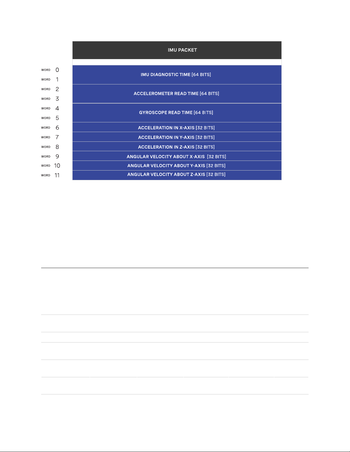
Note that the first timestamp (Words0,1)is fordiagnostics only and is rarelyused under normal operation.
Thesecond twotimestamps,(Words2,3)and(Words4,5),aresampled onthe sameclock asthelidar
data,so should be used formost applications.
Ousterprovidestimestampsforboththegyroandaccelerometerinordertogiveaccesstothelowest
levelinformation. Inmostapplications it is acceptable touse the averageof the twotimestamps.
3.4 DataRates
The table below calculates the data of all products operating at the highest lidar modes, 2048x10 or
1024x20 and assuming a default azimuth window of 360°. Providing a custom azimuth window can
further lower data rate. See the Azimuth Window section for details on setting a custom azimuth
window.
Product Lidar packet
size(Bytes)
OS1-16 3,392 1,280 48 100 34.77
OS0-32, OS1-
32,OS2-32
OS0-64, OS1-
64,OS2-64
OS0-128, OS1-
128,OS2-128
6,464 1,280 48 100 66.23
12,608 1,280 48 100 129.14
24,896 1,280 48 100 254.97
Lidar packets
rate* (Hz)
19
IMU packet
size(Bytes)
IMU packets
persecond
Data rate
(Mbps)
Page 20

Lidar packets account for >99% of data coming from the sensor. For most applications, a gigabit
Ethernetnetwork connection isrequiredfor reliableperformance.
3.5 RangePerformancebyLidar Mode
Dependinguponthe sensor’slidarmode, thesensor canhavean rangeboostmultiplier fromitsbaselinerangeaslistedonthe datasheet. Thebaselinerangeisbasedoff1024x20or2048x10 lidarmode.
Thetable below showsthe range boost multiplierforoperating inotherlidar modes.
FrameRate / Horiz. Res 512 1024 2048
10Hz 1.4x 1.2x 1x
20Hz 1.2x 1x N/A
20
Page 21

4 KeyFeatures
4.1 AzimuthWindow
Configuring the azimuth window is a feature to only turn on the UDP lidar data within a region of
interest. The region of interest is defined by a min bound and a max bound, both in millidegrees. As
areminder,angles in thisframe incrementcounter-clockwisewhen viewedfromthetop. Belowisthe
LidarCoordinate Framefroma top-down perspective:
0°towards theexternalconnector
90°a quarter turn counter-clockwisefromthe connector
180°opposite the connector
270°three quarter turns counter-clockwisefrom the connector
Configuringtheazimuthwindowlowerstheaverageoutputdatarateofthesensorbutdoesnotaffect
thepeak output datarate ofthesensor. Italsodoes not stopthe lasersfromfiring andthusdoes not
havean effecton power consumption orthermals.
21
Page 22

4.1.1 ExpectedSensorBehavior
The sensor will round the input azimuth window bounds tothe nearest Measurement Block IDs generating new ID-based bounds. The new bounds are used to mask Measurement Blocks in the lidar
data packets. Lidarpackets containing only masked Measurement Blocks are not output, and there
may partially masked Measurement Blocks in the two bookended lidar packets in each frame. The
Measurement Block Status field willindicatethe validor masked/paddedMeasurement Blocks in any
partiallymaskedlidar packets. (SeetheLidar Data section fordetailson the lidar data format.)
Thevisualizedoutput willcontain jaggededges causedbythestaggered,nonzeronatureofthebeam
azimuth angles. It is necessary to set more conservative (wider) bounds to push the jagged edges
beyondthe desired window. This can be determinedthrough trial and erroror calculated deterministicallywith knowledge of thequeryablebeam azimuth angles.
4.1.2 Azimuth WindowExamples
TheTCP APIGuidelists the command forsetting an azimuth window. Below areexamplesettings:
set_config_param azimuth_window [min_bound_millidegrees, max_bound_millidegrees]
// defaults setting of 360° window:
set_config_param azimuth_window [0, 360000]
// this will also default to a 360° window
set_config_param azimuth_window [0, 0]
// Set a region of interest between 0° to 180°.
set_config_param azimuth_window [0, 180000]
// Set a region of interest between 270° to 90° with 180° field of view
set_config_param azimuth_window [270000, 90000]
// Set a region of interest 90° to 270° with 180° field of view
set_config_param azimuth_window [90000, 270000]
// Set a region of interest between 0° to 90° with 90° field of view
set_config_param azimuth_window [0, 90000]
// Set a region of interest 90° to 360° with 270° field of view
set_config_param azimuth_window [90000, 0]
4.2 PhaseLock
Phaselocking allowsa sensorto consistentlypass throughaspecific angleat a specifictime on each
rotation. Phaselockingisusefulforsynchronizingasensorwithotherdevicesincludingcamera,radar,
andother lidar.
A sensor must first be time-synchronized from an external source and must be in either the
TIME_FROM_PTP_1588 or TIME_FROM_SYNC_PULSE_IN timestamp_mode beforeentering phaselock.
22
Page 23
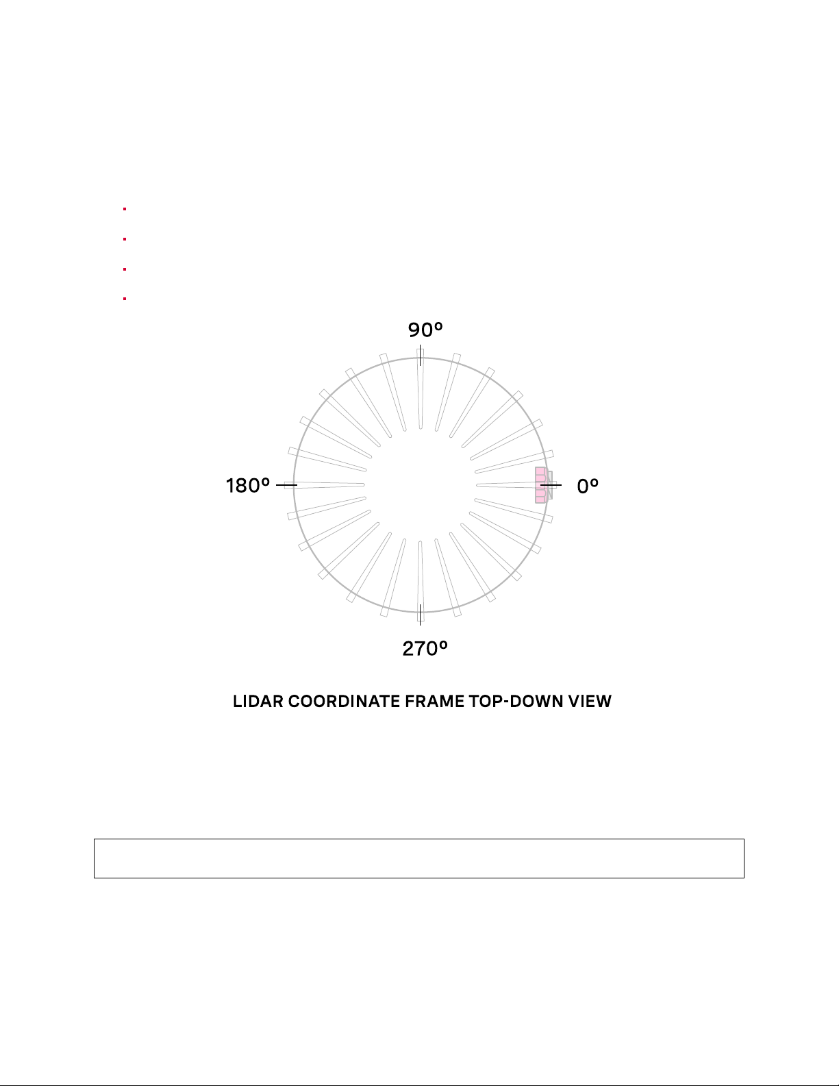
4.2.1 Phase LockingReferenceFrame
Phase locking commands use angles defined in the Lidar Coordinate Frame in millidegrees. As a reminder, angles in this frame increment counter-clockwise when viewed from the top. Below is the
LidarCoordinate Framefroma top-down perspective:
0°towards theexternalconnector
90°a quarter turn counter-clockwisefromthe connector
180°opposite the connector
270°three quarter turns counter-clockwisefrom the connector
4.2.2 Phase Locking Commands
TheTCP APIGuidelists the twocommands needed to acheivephase lock.
Commandto enable or disablephaselock:
// by default, phase_lock_enable is false
set_config_param phase_lock_enable <true/false>
Commandto set the phaselockoffset angle in theLidar Coordinate Frame:
23
Page 24
// by default, phase_lock_offset value is 0
// <angle_in_millidegrees> is an int from [0, 360000]
set_config_param phase_lock_offset <angle_in_millidegrees>
4.2.3 Multi-sensorExample
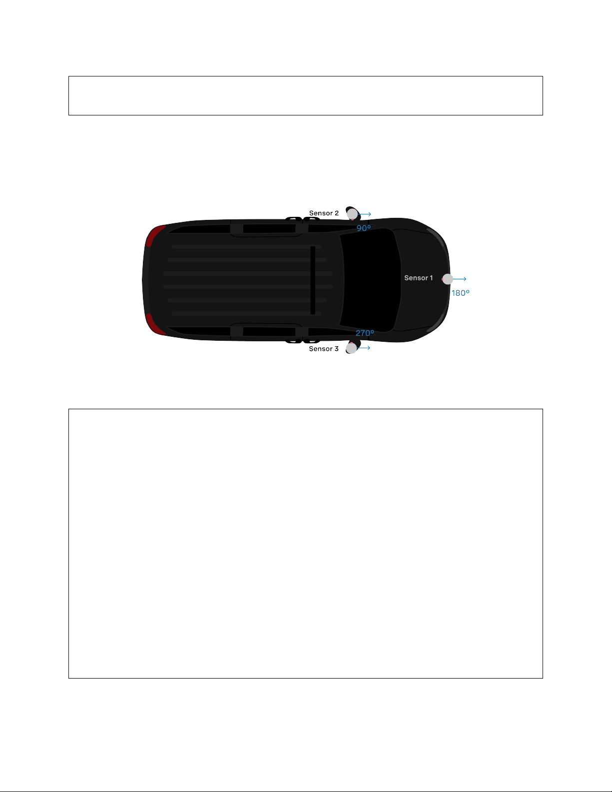
Inthisexamplebelow,wearetryingtophaselockallthreesensorsonthecarsothattheypointtowards
thefrontofthe carat thesame time. Notethat theirexternalconnectorspoint indifferentdirections.
Assumingthethreesensorsareproperlytimesynchronizedviaanexternalsource,thefollowingshows
the netcat console input commands and responses from configuring the sensors so that they point
forwardat the sametime:
// set Sensor 1 to phase lock at 180°
$ nc sensor1_hostname 7501
set_config_param phase_lock_enable true
set_config_param
set_config_param phase_lock_offset 180000
set_config_param
reinitialize
reinitialize
save_config_params
save_config_params
// set Sensor 2 to phase lock at 90°
$ nc sensor2_hostname 7501
set_config_param phase_lock_enable true
set_config_param
set_config_param phase_lock_offset 90000
set_config_param
reinitialize
reinitialize
save_config_params
save_config_params
// set Sensor 2 to phase lock at 270°
$ nc sensor3_hostname 7501
(continuesonnextpage)
24
Page 25

(continuedfrompreviouspage)
set_config_param phase_lock_enable true
set_config_param
set_config_param phase_lock_offset 270000
set_config_param
reinitialize
reinitialize
save_config_params
save_config_params
4.2.4 Accuracy
Thefollowingchartshowstheexpectedangularpositionaccuracyundernormaloperatingconditions.
ProductLine Accuracy
10Hz 20 Hz
OS0and OS1 (Gen1 and Gen 2) 0.5˚ 0.5˚
OS2 5˚ 10˚
4.2.5 Phase Locking Alerts
Thefollowingalertsrelatedtophaselockingerrorsarelistedbelow. Forthefulllistofalertsanderrors
seethe Alerts and Errors sectionin the Appendix.
Table4.1: Phase LockAlerts
id category level description
0x01000050 MOTOR_CONTROL WARNING The phase lock offset error has exceeded the
threshold.
0x01000051 MOTOR_CONTROL ERROR The phase lock control failed to achieve a
lock multiple times; please contact Ouster at
https://ouster.com/tech-support.
0x01000024 STARTUP ERROR Thephaselockcontrolfailedtoachievealock
duringstartup.
25
Page 26

4.3 StandbyOperatingMode
Startingthe firmwarev2.0.0,thesensor canbecommanded inand outofa low-powerStandbyOperatingMode that can be usefulfor power,battery,or thermal-conscious applications of thesensor.
The TCPconfig paramoperating_mode has a default value of "NORMAL". Setting it to"STANDBY" puts the
sensorinto Standby OperatingModeupon reinitialization.
4.3.1 ExpectedSensor Behavior
Powerdraw in Standby mode 5W. The motor does not spin, and light is not visible from the window.
However,thesensor is on and listeningto commands. The sensorstatuswill be "STANDBY".
4.3.2 Standby Operating Mode Examples
Belowareexample netcatconsole commandinput andresponses forseveralusecaesof theStandby
mode
// set sensor into Standby mode and keep sensor in Standby mode upon power-up at next use
set_config_param operating_mode "STANDBY"
set_config_param
reinitialize
reinitialize
save_config_params
save_config_params
// set sensor into Standby mode but have sensor start in the default Running mode upon power-up at next use:
set_config_param operating_mode "STANDBY"
set_config_param
reinitialize
reinitialize
// command sensor back into Running mode and save config
set_config_param operating_mode "NORMAL"
set_config_param
reinitialize
reinitialize
save_config_params
save_config_params
Note: auto_start_flag is the deprecated parameter name where auto_start_flag 0 is equivalent to
operating_mode "STANDBY" and auto_start_flag 1 is equivalent to operating_mode "NORMAL". Please use
operating_mode wherever possibleinclient code.
Warning: Useof auto_start_flag in firmwareprior tov2.0.0hasunexpectedbehavior.
26
Page 27

4.4 ColdStart
Startingin v2.0.0,thereissoftware-enabledcapabilityforpower-upfromlower temperaturesforGen
2sensors. Ifthesensor detects that its environmentaltemperature is low,it will attempt toself-heat
ina warmup state beforeentering anormaloperating state.
4.4.1 HardwareRequirements
Gen 1 sensors are not cold start-compatible on any firmware. While all sensors will attempt to start
at lower exhibit cold start behavior by going into the warmup state, only Gen 2 sensors are able to
successfullyexit the warmup stateintothe normal operatingstate.
4.4.2 Cold StartOperation
Thereisnothing fortheusertochange aboutthe sensorconfiguration touse thisfeature. Thesensor
willautomatically begin itswarmupprocess in the coldestpartsof its operatingtemperaturerange.
ProductLine Mintemp specs
OS0
OS1
OS2
-40°Cmin operating temp
8mins to SENSOR_RUNNING
12mins to lasersattemp (full range)
28Wpeak power
-40°Cmin operating temp
8mins to SENSOR_RUNNING
12mins to lasersattemp (full range)
28Wpeak power
-5°Cmin operating temp
22mins to SENSOR_RUNNING
22mins to lasersattemp (full range)
30Wpeak power
27
Page 28

4.4.3 Indicationsand Alerts
In a cold start scenario, the sensor will have a short warmup phase; we’ve added in the additional
"WARMUP" status to indicatewhenthe sensor is warming up.
$ nc os-992000123456 7501
get_sensor_info
{
"base_pn": "000-101323-03",
"base_sn": "101933001839",
"build_date": "2020-05-15T18:21:21Z",
"build_rev": "v2.0.0",
"image_rev": "ousteros-image-prod-aries-v2.0.0-20201120210617-staging",
"prod_line": "OS-1-128",
"prod_pn": "840-101855-02",
"prod_sn": "99200123456",
"proto_rev": "v1.1.1",
"status": "WARMUP"
}
Thefollowing alerts arerelated tocoldstart
Table4.2: Cold Start Alerts
id category level description
0x01000053 WARMUP_ISSUE ERROR Sensorwarmupprocess has failed.
0x0100004F WARMUP_ISSUE WARNING Sensor warmup process is taking longer
than expected; please ensure sensor is
thermallyconstrained per requirements.
28
Page 29
5 TimeSynchronization
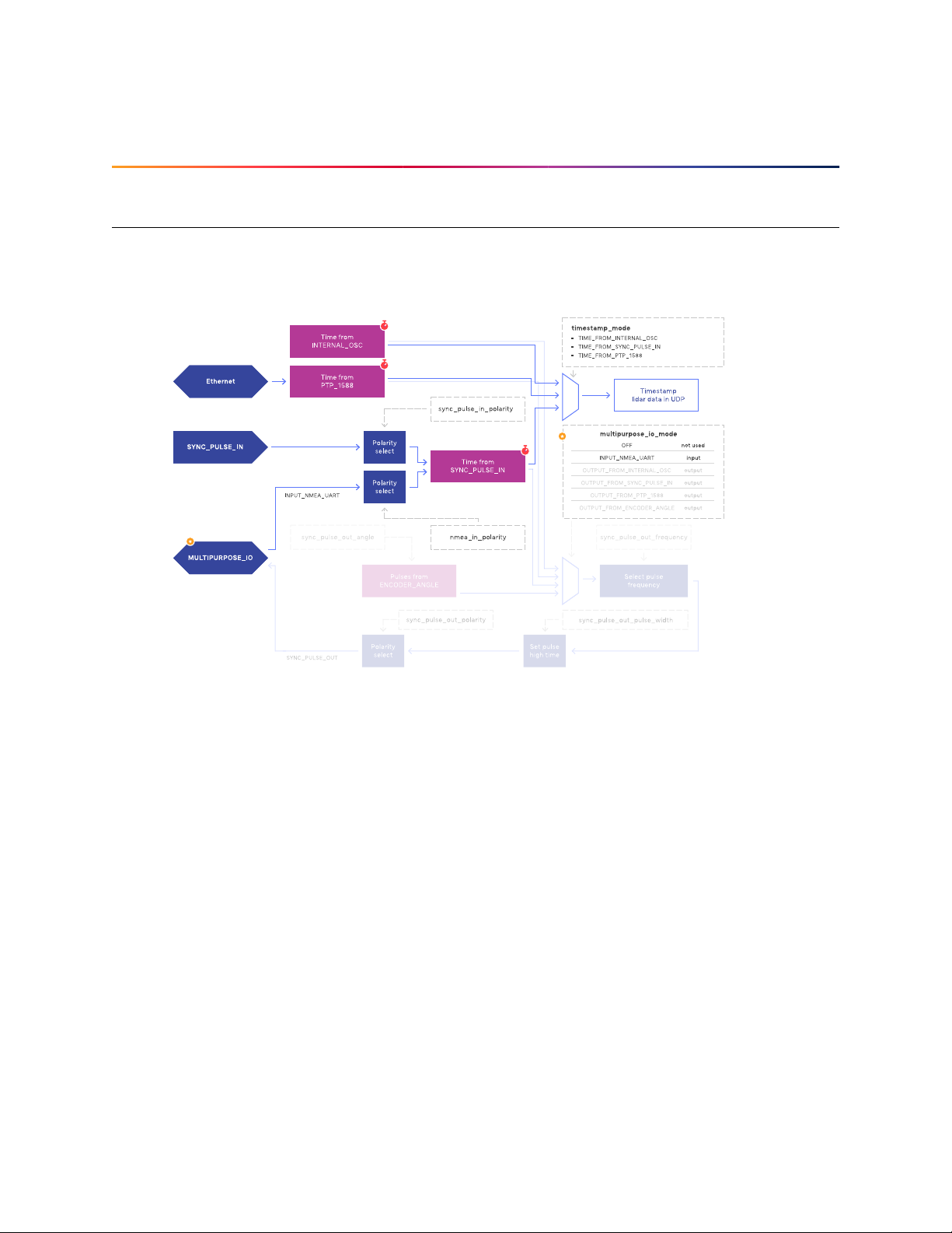
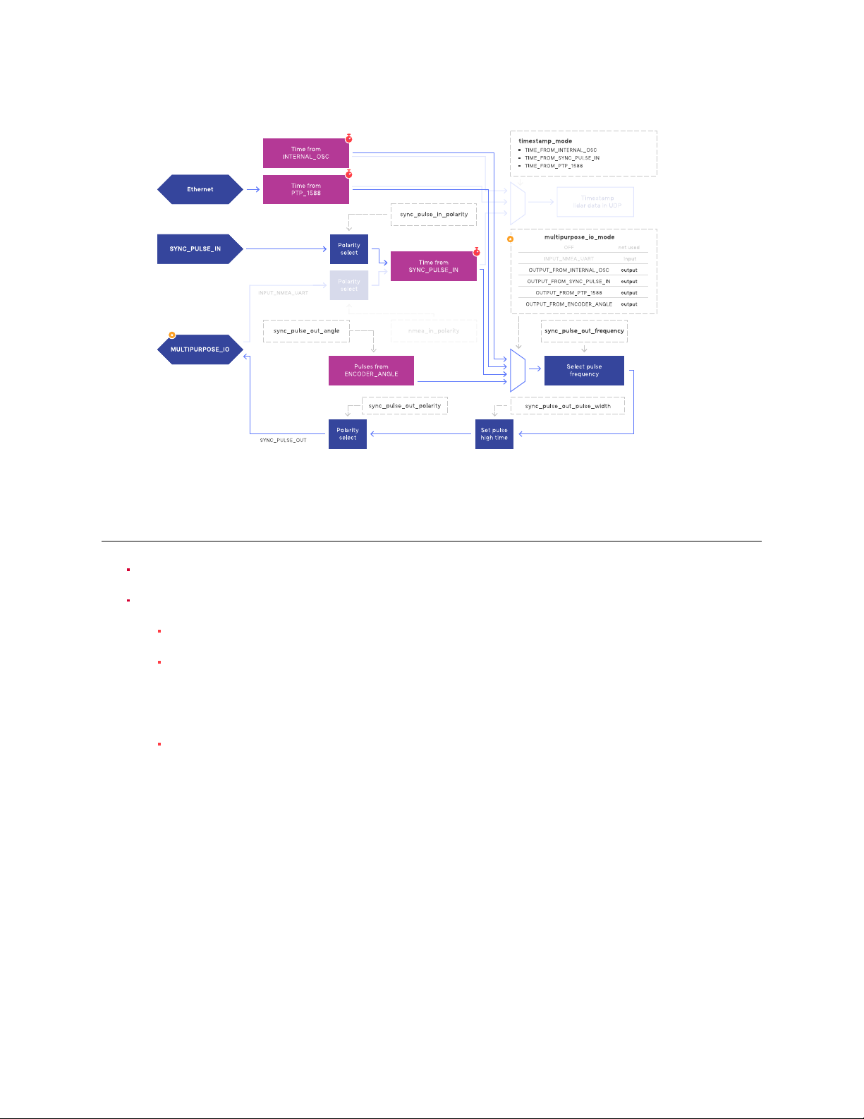
5.1 TimingOverview Diagram
Signalpath with MULTIPURPOSE_IOset asinput
Signalpath with MULTIPURPOSE_IOset asoutput
29
Page 30
5.2 SensorTime Source
Alllidar and IMU data aretimestamped to a commontimer with 10 nanosecond precision.
Thecommon timer can be programmedto run off oneof three clock sources:
Aninternal clock derivedfroma high accuracy,lowdriftoscillator.
An opto-isolated digital input from the external connector for timing off an external hard-
waretrigger suchas a GPS.The polarity ofthis input signalis programmable. Forinstance,
bothaGPSPPSpulseanda30Hzframesyncfromanindustrialcameracansupplyatiming
signalto the sensor.
UsingtheIEEE 1588 Precision Time Protocol. PTP provides the convenienceof configuring
timingover a networkthat supports IEEE 1588withno additional hardwaresignals.
5.2.1 Setting Ouster Sensor Time Source
The source for measurement timestamps can be configured using the set_timestamp_mode TCP command. Theavailable modes aredescribed below:
30
Page 31

Table5.1: Timestamp Modes
Command Response
TIME_FROM_INTERNAL_OSC Usethe internal clock. Measurements are time stamped with ns
sincepower-on. Freerunning counterbased onthe sensor’sinternaloscillator. Counts secondsandnanoseconds sincesensorturn
on,reportedat ns resolution(botha second and nanosecond registerin everyUDPpacket), butminincrement is ontheorder of 10
ns.
TIME_FROM_SYNC_PULSE_IN A free running counter synced to the SYNC_PULSE_IN input
countsseconds(# of pulses)and nanoseconds since sensor turn
on. Ifmultipurpose_io_mode is set to INPUT_NMEA_UART then the secondsregisterjumpstotimeextractedfromaNMEA$GPRMCmessage read on the multipurpose_io port. Reported at ns resolution
(bothasecond andnanosecondregisterineveryUDP packet),but
minincrement is on theorderof 10 ns.
TIME_FROM_PTP_1588 Synchronize with an external PTP master. A monotonically in-
creasing counter that will begin counting seconds and nanoseconds since startup. As soon as a 1588 sync event happens, the
timewillbeupdatedtosecondsandnanosecondssince1970. The
counter must always count forward in time. If another 1588 sync
event happens the counter will either jump forward to match the
newtime, or slow itselfdown. It is reported atnsresolution (there
is both a second and nanosecond register in every UDP packet),
butthe minimum increment varies.
If configuring the sensor to synchronize time from an external sync pulse, the pulse polarity can be
specifiedasdescribed in the TCPAPI Guide. Pulse-in frequency is assumed to be 1 Hz. Forexample,
the below commands will set the sensor to expect an active low pulse and configure the seconds
timetampto be pulse countsincesensor startup:
set_config_param timestamp_mode TIME_FROM_SYNC_PULSE_IN
set_config_param sync_pulse_in_polarity ACTIVE_LOW
reinitialize
Ifdesired toconfigure themultipurpose-io port ofthesensor toacceptan externalNMEA UARTmessage,themultipurpose_io_mode parametermustbesettoINPUT_NMEA_UART asdescribedinExternalTrig-
ger Clock Source. Once a valid UART message is recievedby the sensor, the seconds timetamp will
snap to the latest timestamp recieved. The expected NMEA UART message is configurable as described in TCP API Guide. For example, the belowcommands will set the sensor to accept an NMEA
UARTmessage that isactive high with a baud rate of 115200 bits per second, add 27 additional leap
seconds,and accept messages evenwith a valid characternot set:
set_config_param multipurpose_io_mode INPUT_NMEA_UART
set_config_param nmea_in_polarity ACTIVE_HIGH
set_config_param nmea_baud_rate BAUD_115200
31
Page 32

set_config_param nmea_leap_seconds 27
set_config_param nmea_ignore_valid_char 1
reinitialize
5.2.2 ExternalTrigger ClockSource
Additionally, the sensor can be configured to output a SYNC_PULSE_OUT signal from a variety of
sources. See example commands in theTCP API section. Pulses willalwaysbe evenlyspaced.
Thiscan be enabled throughthemultipurpose_io_mode configuration parameter.
Configuration Response
Donot output a SYNC_PULSE_OUTsignal.
OFF
Reconfigures the MULTIPURPOSE_IOport as an input.
INPUT_NMEA_UART
See Setting Ouster Sensor Time Source for more information.
Output a SYNC_PULSE_OUT signal synchronized with
OUTPUT_FROM_INTERNAL_OSC
theinternal clock.
Output a SYNC_PULSE_OUT signal synchronized with
OUTPUT_FROM_SYNC_PULSE_IN
aSYNC_PULSE_INprovidedto theunit.
Output a SYNC_PULSE_OUT signal synchronized with
OUTPUT_FROM_PTP_1588
anexternal PTP IEEE1588master.
Outputa SYNC_PULSE_OUTsignal with a userdefined
OUTPUT_FROM_ENCODER_ANGLE
ratein an integernumber of degrees.
Whenthesensor’smultipurpose_io_mode is set to OUTPUT_FROM_INTERNAL_OSC, OUTPUT_FROM_SYNC_PULSE_IN,
orOUTPUT_FROM_PTP_1588,then sync_pulse_out_frequency (Hz) parameter can be used to define the outputrate. It defaults to 1 Hz. It should be greater than 0 Hz and maximum sync_pulse_out_frequency is
limitedby the criterionbelow.
When the sensor is set to OUTPUT_FROM_ENCODER_ANGLE, then the sync_pulse_out_angle (deg) parameter
canbe used todefine the output pulse rate. This allows the user to output a SYNC_PULSE_OUTsignal when the encoder passes a specified angle, or multiple of the angle, indexed from 0 crossing,
in degrees. It should be an integer between 0 and 360 degrees, inclusive. However, the minimum
sync_pulse_out_angle is also limited bythecriterion below.
Inall modes, the output pulsewidth is defined by sync_pulse_out_pulse_width (ms).
Note: Ifsync_pulse_out_pulse_width x sync_pulse_out_frequency is closeto 1second, theoutput pulses
will not function (will not return to 0). For example, at 10 Hz rotation and a 10 ms pulse width, the
limitationon the number of pulsesper rotation is 9.
32
Page 33

EXAMPLECOMMANDS:Hereareexamplecommandsandtheireffectonoutputpulsewhenlidar_mode
is1024x10, and assuming sync_pulse_out_pulse_width is10 ms.
→
Command Response
The output pulse frequency is 1 Hz. Each pulse
set_config_param multipurpose_io_mode
OUTPUT_FROM_SYNC_PULSE_IN
set_config_param sync_pulse_out_pulse_width 10
set_config_param sync_pulse_out_frequency 1
reinitialize
set_config_param multipurpose_io_mode
OUTPUT_FROM_SYNC_PULSE_IN
set_config_param sync_pulse_out_frequency 50
reinitialize
set_config_param multipurpose_io_mode
OUTPUT_FROM_ENCODER_ANGLE
set_config_param sync_pulse_out_angle 360
reinitialize
is 10 ms wide. sync_pulse_out_pulse_width and
sync_pulse_out_frequency commands are optionalbe-
causethey just re-command the defaultvalues
Theoutputpulsefrequencyis 50 Hz. Each pulse is 10
mswide.
Theoutputpulse frequency is10Hz, since thesensor
is in 10 Hz mode (10 rotations / sec) and the angle is
setto 360º, a full rotation. Each pulseis 10ms wide.
Theoutputpulsefrequencyis80Hz,sincethesensor
set_config_param multipurpose_io_mode
OUTPUT_FROM_ENCODER_ANGLE
set_config_param sync_pulse_out_angle 45
reinitialize
is in 10 Hz mode (10 rotations / sec) and the angle is
setto 45º. Each full rotationwill have8 pulses. Each
pulseis 10 ms wide.
5.3 NMEAMessageFormat
TheOusterSensor expectsa standardNMEA $GPRMC UARTmessage. Data (called a sentence) is a
simpleASCIIstringstarting with a‘$’characterandending with areturn character. Fields of thesentenceareseparatedwitha‘,’character,andthelastfield(achecksum)is separatedby a‘*’ character.
The max character length of a standard message is 80 characters; however, the Ouster Sensor can
supportnon-standardmessages up to85characters (seeExample 2 below).
TheOusterSensorwilldelivertimeintheUDPpacketbycalculatingsecondssince00:00:00Thursday,
1 January 1970. nmea_leap_seconds by default is 0, meaning this calculation will not take intoaccount
anyleap seconds. If nmea_leap_seconds is0 then the reportedtimeis Unix Epoch time. AsofFebruary,
2019CoordinatedUniversalTime (UTC)lagsbehindInternationalAtomicTime(TAI)byanoffsetof37
33
Page 34

seconds(10secondsfromthe initial UTC offset when UTCwas introduced in 1972 + 27 leap seconds
announced in the intervening years). Therefore, setting nmea_leap_seconds to 37 in February of 2019
wouldmake the timestampsmatch the TAIstandard.
nmea_in_polarity bydefaultis ACTIVE_HIGH. This means that a UART start bit will occur directly after a
fallingedge. If using RS-232,the UART signalmaybe inverted(wherea start bit occursdirectly after
arising edge). In thiscase,nmea_in_polarity should be settoACTIVE_LOW.
Example1 Message:
$GPRMC,123519,A,4807.038,N,01131.000,E,022.4,084.4,230394,003.1,W*6A
→
Field Description
$GPRMC RecommendedMinimum sentence C
123519 Fixtakenat12:35:19 UTC
A StatusA=activeorV=Void
4807.038 Latitude 48deg 07.038’
N Latitudecardinalreference
01131.000 Longitude11 deg31.000’
E Longitude cardinalreference
022.4 Speed overtheground inknots
084.4 Trackanglein degrees True
230394 Date- 23rd ofMarch 1994
003.1 MagneticVariation
W Magneticcardinal reference
A [Optional]A=autonomous,D=differential,E=Estimated, N=not valid, S=Simulator
*6A Thechecksum data, alwaysbegins with *
Example2 Message:
$GPRMC,042901.00,A,3745.871698,N,12224.825960,W,0.874,327.72,130219,13.39,E,A,V*60
→
34
Page 35

Field Description
$GPRMC RecommendedMinimum sentence C
042901.00 Fixtaken at 4:29:01UTC
A StatusA=activeor V=Void
3745.871698 Latitude 37 deg 45.871698’
N Latitudecardinalreference
12224.825960 Longitude12 deg 24.825960’
W Longitudecardinal reference
0.874 Speed over the ground in knots
327.72 Trackanglein degrees True
130219 Date-13th ofFebruary2019
13.39 MagneticVariation
E Magneticcardinal reference
A [Optional]A=autonomous,D=differential,E=Estimated,N=notvalid, S=Simulator
*60 Thechecksum data, alwaysbegins with *
6 InputsandInterfaces
35
Page 36
6.1 WebInterface
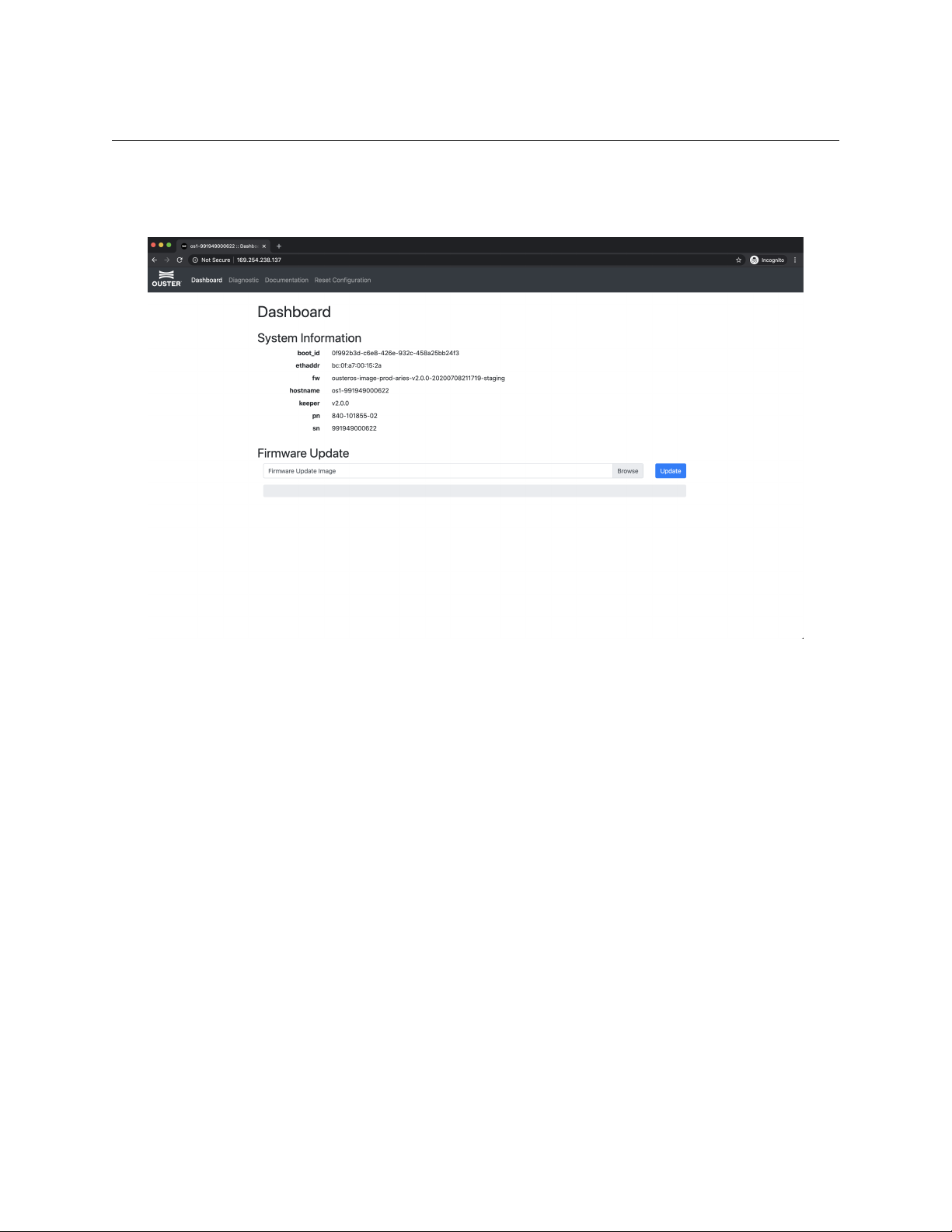
Thesensor homepage can be access by typing in thesensor’saddress (IPv4, IPv6, or hostname)in a
webbrowser. Fromhere you canseeinformation about the sensor,access documentation, and reset
sensorsettings.
Figure6.1:The sensorhomepage, accessedthrough its IPv4link-local address
Dashboard: Containsbasic informationaboutthesensor. Youcanupdatefirmwareonthispage. See
Updating Firmware formoredetails.
Diagnostic: Contains diagnostic alert and error information about the sensor for troubleshooting
purposes. Fora listofpossible alerts and errors,see Alerts and Errors.
Documentation: Contains the HTTP and TCP API guides that are compatible the version of the
firmware on the sensor. See www.ouster.com for latest hardware and software user manuals and
datasheets.
ResetConfiguration: Resetssensor tofactoryconfigurationsandsettings. Notethatthisresetsany
staticIP address giventothe sensor.
36
Page 37

6.2 Electricaland Mechanical Interface
Forinformation on the mechanical interface, electrical interface, or the InterfaceBox, please refer to
theHardware User Manual
37
Page 38

7 Troubleshooting
7.1 SensorHomepageandHTTPServer
ThesensorHTTPserverpagehttp://os-991900123456.local/hasDashboard,Diagnostics,Documentation
andReset Configuration buttons:
Dashboard: Current page that lists some basic sensor information, and allows sensor firmware
upgrade.
Diagnostics: Diagnostic information and system journal that can be downloaded and included
whencontacting Ouster forservice.
Documentation: SensorTCP andHTTP APIGuide
Reset Configuration: Sensor factoryconfigurationthat can be reset to if desired. This will erase
anycustom configurationthatyou set on thesensorpreviously.
7.2 Networking
Manyinitialproblemswiththesensorareassociatedwithit notproperlybeingassigned anIPaddress
bya network switchor DHCP server on a client computer. Check your networkingsettings,the steps
inConnecting to Sensor,and thatallwires arefirmlyconnectedif yoususpectthis problem. Note that
if the sensor is not connected via gigabit Ethernet, it will stop sending data and will output an error
code if it fails to achieve a 1000 Mb/s+ full duplex link. Please see the Networking Guide for detailed
guidanceon network setup.
7.3 get_alerts
Tocheck forhardware errors,use the get_alerts TCPcommand.
If the watchdog is triggered, an alert code will be appended to the end of the response of the TCP
commandget_alerts. Thesensorhasalimited-sizebufferthatwillrecordthefirstfewalertsdetected
bythe sensor.
Thefull list of possible alertsanderror messages can befoundin Alerts and Errors in the Appendix.
Thealertsreported havethe followingformat:
{
"category": "Category of the alert: e.g. OVERTEMP, UDP_TRANSMISSION",
"level": "Level of alert: e.g. NOTICE, WARNING, ERROR",
"realtime": "The timestamp of the alert in nanoseconds",
"active": "Whether the alert is active or not: <true/false>",
"msg": "A description of the alert",
"cursor": "The sequential number of the alert, starting from 0 counting up",
(continuesonnextpage)
38
Page 39

(continuedfrompreviouspage)
"id": "The hexadecimal identification code of the alert: e.g. 0x01000017",
"msg_verbose": "Any additional verbose description that the alert may present"
}
Example showing active and logged forced temperature sensor failures occuring at timestamps
1569712873477772800, 1569712879991844096, 1569712884968876544 (nanoseconds). The first
loggederror then resolvesitself at 1569713260229536000. The example hasbeen JSON formatted:
{
"active": [
{
"category": "OVERTEMP",
"level": "ERROR",
"realtime": "1569712879991844096",
"active": true,
"msg": "Unit internal temperature out of bounds; please ensure proper heat sinking.",
"cursor": 1,
"id": "0x01000001",
"msg_verbose": ""
},
{
"category": "OVERTEMP",
"level": "ERROR",
"realtime": "1569712884968876544",
"active": true,
"msg": "Unit internal temperature out of bounds; please ensure proper heat sinking.",
"cursor": 2,
"id": "0x01000002",
"msg_verbose": ""
}
],
"next_cursor": 4,
"log": [
{
"category": "OVERTEMP",
"level": "ERROR",
"realtime": "1569712873477772800",
"active": true,
"msg": "Unit internal temperature out of bounds; please ensure proper heat sinking.",
"cursor": 0,
"id": "0x01000000",
"msg_verbose": ""
},
{
"category": "OVERTEMP",
"level": "ERROR",
"realtime": "1569712879991844096",
"active": true,
"msg": "Unit internal temperature out of bounds; please ensure proper heat sinking.",
"cursor": 1,
"id": "0x01000001",
"msg_verbose": ""
},
(continuesonnextpage)
39
Page 40

(continuedfrompreviouspage)
{
"category": "OVERTEMP",
"level": "ERROR",
"realtime": "1569712884968876544",
"active": true,
"msg": "Unit internal temperature out of bounds; please ensure proper heat sinking.",
"cursor":2 ,
"id": "0x01000002",
"msg_verbose": ""
},
{
"category": "OVERTEMP",
"level": "ERROR",
"realtime": "1569713260229536000",
"active": false,
"msg": "Unit internal temperature out of bounds; please ensure proper heat sinking.",
"cursor": 3,
"id": "0x01000000",
"msg_verbose": ""
}
]
}
7.4 UsingLatestFirmware
Upgradingtothelatestfirmwarecanoftenresolveissuesfoundinearlierfirmware. Thelatestfirmware
isalwaysfoundat www.ouster.com/resources. OurSupportteamisbestsuitedtobe abletohelpyou
ifyou are runningthelatest firmware.
40
Page 41

8 HTTP APIReference
HTTPAPI developerreferenceguide. Thisdocumentsthe interfaceforHTTPAPIandisaccessible via
/api/v1 on the sensor hostedHTTP server.
8.1 system/firmware
8.1.1 GET/api/v1/system/firmware
GET 192.0.2.123/api/v1/system/firmware
Getthe firmwareversionof the sensor
GET /api/v1/system/firmware HTTP/1.1
Host: 192.0.2.123
HTTP/1.1 200 OK
Host: 192.0.2.123
content-type: application/json; charset=UTF-8
{
"fw": "ousteros-image-prod-aries-v2.0.0"
}
→
ResponseJSONObject
fw (string) – Running firmware image name and version.
StatusCodes
200OK –No error
8.2 diagnostics
8.2.1 GET /api/v1/diagnostics/dump
GET 192.0.2.123/api/v1/diagnostics/dump
Getthe diagnostics files of thesensor
GET /api/v1/diagnostics/dump HTTP/1.1
Host: 192.0.2.123
HTTP/1.1 200 OK
content-disposition: attachment; filename="192.0.2.123_diagnostics-dump_29811b9e-2afc-11eb-ae01-
,→bc0fa700190c.bin"
content-type: application/octet-stream
{binary data}
41
Page 42

→
StatusCodes
200OK –No error
8.3 system/network
8.3.1 GET/api/v1/system/network
GET 192.0.2.123/api/v1/system/network
Getthe system networkconfiguration.
GET /api/v1/system/network HTTP/1.1
Host: 192.0.2.123
HTTP/1.1 200 OK
content-type: application/json; charset=UTF-8
{
"carrier": true,
"duplex": "full",
"ethaddr": "bc:0f:a7:00:01:2c",
"hostname": "os-991900123456",
"ipv4": {
"addr": "192.0.2.123/24",
"link_local": "169.254.245.183/16",
"override": null
},
"ipv6": {
"link_local": "fe80::be0f:a7ff:fe00:12c/64"
},
"speed": 1000
}
→
ResponseJSONObject
carrier (boolean) – State of Ethernetlink, true when physicallayeris connected.
duplex (string) – Duplex mode of Ethernet link,half orfull.
ethaddr (string) – Ethernet hardware (MAC)address.
hostname (string)–Hostname of thesensor,alsoused when requestingDHCP addressandreg-
isteringmDNS hostname.
ipv4 (object) – See ipv4 object
ipv6.link_local (string) – Link-local IPv6 address.
speed (integer) – Ethernet physical layerspeed in Mbps,should be1000 Mbps.
StatusCodes
200OK –No error
42
Page 43

8.3.2 GET /api/v1/system/network/ipv4
GET 192.0.2.123/api/v1/system/network/ipv4
Getthe IPv4 networkconfiguration.
GET /api/v1/system/network/ipv4 HTTP/1.1
Host: 192.0.2.123
HTTP/1.1 200 OK
content-type: application/json; charset=UTF-8
{
"addr": "192.0.2.123/23",
"link_local": "169.254.245.183/16",
"override": null
}
→
ResponseJSONObject
addr (string) – Current global orprivate IPv4address.
link_local (string) – Link-local IPv4 address.
override (string) – StaticIP override value, thisshould matchaddr. This valuewill be null when
unsetand operating in DHCP orlink-local modes.
StatusCodes
200OK –No error
8.3.3 GET /api/v1/system/network/ipv4/override
GET 192.0.2.123/api/v1/system/network/ipv4/override
Getthe current IPv4 staticIPaddress override.
GET /api/v1/system/network/ipv4/override HTTP/1.1
Host: 192.0.2.123
HTTP/1.1 200 OK
content-type: application/json; charset=UTF-8
null
→
ResponseJSONObject
string –Static IP overridevalue,this should matchaddr. This valuewill be null when unset and
operatingin DHCP mode.
StatusCodes
200OK –No error
43
Page 44

8.3.4 PUT /api/v1/system/network/ipv4/override
PUT 192.0.2.123/api/v1/system/network/ipv4/override
Overridethe default dynamicbehaviorand set astaticIP address.
Note: The sensor will reset the networkconfiguration aftera short sub second delay (to allow
fortheHTTPresponsetobesent). Afterthis delaythesensorwillonlybereachableonthenewly
setIPv4 address.
The sensor needs to be reachable either by link-local or dynamic DHCP configuration or by an
existingstatic IP overridefromthe host reconfiguringthesensor.
Warning: If an unreachable network address is set, the sensor will become unreachable.
Tools such as avahi-browse, dns-sd, or mDNS browser can help with finding a sensor on a
network.
Static IP override should only be used in special use cases. The link-local configuration is
recommendedwhere possible.
PUT /api/v1/system/network/ipv4/override HTTP/1.1
Content-Type: application/json
Host: 192.0.2.123
"192.0.2.100/24"
→
RequestJSONObject
string – Static IP override valuewith subnetmask
ResponseJSONObject
string – Static IP override valuethat systemwillset aftera shortdelay.
StatusCodes
200OK –No error
8.3.5 DELETE /api/v1/system/network/ipv4/override
DELETE 192.0.2.123/api/v1/system/network/ipv4/override
Deletethe static IP overridevalue and returntodynamic configuration.
Note: The sensor will reset the networkconfiguration aftera short sub second delay (to allow
fortheHTTPresponsetobesent). Afterthis delaythesensorwillonlybereachableonthenewly
setIPv4 address.
Thesensor maybeunreachable forseveral secondswhile a link-local leaseis obtained fromthe
networkor client machine.
DELETE /api/v1/system/network/ipv4/override HTTP/1.1
Host: 192.0.2.123
44
Page 45

→
StatusCodes
204No Content – No error,nocontent
8.4 time
8.4.1 GET /api/v1/time
GET 192.0.2.123/api/v1/time
Getthe system timeconfigurationfor alltimingcomponents of the sensor.
GET /api/v1/time HTTP/1.1
Host: 192.0.2.123
HTTP/1.1 200 OK
content-type: application/json; charset=UTF-8
{
"ptp": {
"current_data_set": {
"mean_path_delay": 37950,
"offset_from_master": -211488,
"steps_removed": 1
},
"parent_data_set": {
"gm_clock_accuracy": 33,
"gm_clock_class": 6,
"gm_offset_scaled_log_variance": 20061,
"grandmaster_identity": "001747.fffe.700038",
"grandmaster_priority1": 128,
"grandmaster_priority2": 128,
"observed_parent_clock_phase_change_rate": 2147483647,
"observed_parent_offset_scaled_log_variance": 65535,
"parent_port_identity": "001747.fffe.700038-1",
"parent_stats": 0
},
"port_data_set": {
"announce_receipt_timeout": 3,
"delay_mechanism": 1,
"log_announce_interval": 1,
"log_min_delay_req_interval": 0,
"log_min_pdelay_req_interval": 0,
"log_sync_interval": 0,
"peer_mean_path_delay": 0,
"port_identity": "bc0fa7.fffe.00012c-1",
"port_state": "SLAVE",
"version_number": 2
},
"time_properties_data_set": {
"current_utc_offset": 37,
"current_utc_offset_valid": 1,
(continuesonnextpage)
45
Page 46

"frequency_traceable": 1,
"leap59": 0,
"leap61": 0,
"ptp_timescale": 1,
"time_source": 32,
"time_traceable": 1
},
"time_status_np": {
"cumulative_scaled_rate_offset": 0,
"gm_identity": "001747.fffe.700038",
"gm_present": true,
"gm_time_base_indicator": 0,
"ingress_time": 1552413985821448000,
"last_gm_phase_change": "0x0000'0000000000000000.0000",
"master_offset": -211488,
"scaled_last_gm_phase_change": 0
}
},
"sensor": {
"nmea": {
"baud_rate": "BAUD_9600",
"diagnostics": {
"decoding": {
"date_decoded_count": 0,
"last_read_message": "",
"not_valid_count": 0,
"utc_decoded_count": 0
},
"io_checks": {
"bit_count": 1,
"bit_count_unfiltered": 0,
"char_count": 0,
"start_char_count": 0
}
},
"ignore_valid_char": 0,
"leap_seconds": 0,
"locked": 0,
"polarity": "ACTIVE_HIGH"
},
"sync_pulse_in": {
"diagnostics": {
"count": 1,
"count_unfiltered": 0,
"last_period_nsec": 0
},
"locked": 0,
"polarity": "ACTIVE_HIGH"
},
"sync_pulse_out": {
"angle_deg": 360,
"frequency_hz": 1,
"mode": "OFF",
"polarity": "ACTIVE_HIGH",
(continuedfrompreviouspage)
(continuesonnextpage)
46
Page 47

"pulse_width_ms": 10
},
"timestamp": {
"mode": "TIME_FROM_INTERNAL_OSC",
"time": 57178.44114677,
"time_options": {
"internal_osc": 57178,
"ptp_1588": 1552413986,
"sync_pulse_in": 1
}
}
},
"system": {
"monotonic": 57191.819600378,
"realtime": 1552413949.3948405,
"tracking": {
"frequency": -7.036,
"last_offset": 5.942e-06,
"leap_status": "normal",
"ref_time_utc": 1552413947.8259742,
"reference_id": "70747000",
"remote_host": "ptp",
"residual_frequency": 0.006,
"rms_offset": 5.358e-06,
"root_delay": 1e-09,
"root_dispersion": 0.000129677,
"skew": 1.144,
"stratum": 1,
"system_time_offset": -2.291e-06,
"update_interval": 2
}
}
}
(continuedfrompreviouspage)
→
ResponseJSONObject
string – See sub objects fordetails.
StatusCodes
200OK –No error
8.4.2 GET /api/v1/time/system
GET 192.0.2.123/api/v1/time/system
Gettheoperatingsystemtimestatus. Thesevaluesrelatetothesensoroperatingsystemclocks,
andnot clocks relatedto hardwaretimestampdata from the lidarsensor.
GET /api/v1/time/system HTTP/1.1
Host: 192.0.2.123
HTTP/1.1 200 OK
content-type: application/json; charset=UTF-8
(continuesonnextpage)
47
Page 48

{
"monotonic": 345083.599570944,
"realtime": 1551814510.730453,
"tracking": {
"frequency": -6.185,
"last_offset": -3.315e-06,
"leap_status": "normal",
"ref_time_utc": 1551814508.1982567,
"reference_id": "70747000",
"remote_host": "ptp",
"residual_frequency": -0.019,
"rms_offset": 4.133e-06,
"root_delay": 1e-09,
"root_dispersion": 0.000128737,
"skew": 1.14,
"stratum": 1,
"system_time_offset": 4.976e-06,
"update_interval": 2
}
}
→
ResponseJSONObject
monotonic (float) – Monotonic time of operating system. This timestamp never counts back-
wardsand is the time sinceboot inseconds.
realtime (float)–TimeinsecondssincetheUnixepoch,shouldmatchwalltimeifsynchronized
withexternal time source.
tracking (object) – Operating system timesynchronization tracking status. See chronyctrack-
ingdocumentation for moreinformation.
StatusCodes
200OK –No error
(continuedfrompreviouspage)
Systemtracking fields ofinterest:
→
Rms_offset Long-termaverageoftheoffset value.
System_time_offset Time delta (in seconds) between estimate of the operating system time and the
currenttrue time.
Last_offset Estimatedlocaloffseton thelast clockupdate.
Ref_time_utc UTCTime atwhich thelast measurementfromthe referencesourcewas processed.
Remote_host This is either ptp if the system is synchronizing to a PTP time source or the address of a
remoteNTPserver thesystem has selectedif thesensor isconnected to theInternet.
48
Page 49

8.4.3 GET/api/v1/time/ptp
GET 192.0.2.123/api/v1/time/ptp
Getthe status of the PTP time synchronization daemon.
Note: See the IEEE 1588-2008 standard for more details on the standard management mes-
sages.
GET /api/v1/time/ptp HTTP/1.1
Host: 192.0.2.123
HTTP/1.1 200 OK
content-type: application/json; charset=UTF-8
{
"current_data_set": {
"mean_path_delay": 30110,
"offset_from_master": 224159,
"steps_removed": 1
},
"parent_data_set": {
"gm_clock_accuracy": 33,
"gm_clock_class": 6,
"gm_offset_scaled_log_variance": 20061,
"grandmaster_identity": "001747.fffe.700038",
"grandmaster_priority1": 128,
"grandmaster_priority2": 128,
"observed_parent_clock_phase_change_rate": 2147483647,
"observed_parent_offset_scaled_log_variance": 65535,
"parent_port_identity": "001747.fffe.700038-1",
"parent_stats": 0
},
"port_data_set": {
"announce_receipt_timeout": 3,
"delay_mechanism": 1,
"log_announce_interval": 1,
"log_min_delay_req_interval": 0,
"log_min_pdelay_req_interval": 0,
"log_sync_interval": 0,
"peer_mean_path_delay": 0,
"port_identity": "bc0fa7.fffe.00012c-1",
"port_state": "SLAVE",
"version_number": 2
},
"time_properties_data_set": {
"current_utc_offset": 37,
"current_utc_offset_valid": 1,
"frequency_traceable": 1,
"leap59": 0,
"leap61": 0,
"ptp_timescale": 1,
"time_source": 32,
(continuesonnextpage)
49
Page 50

"time_traceable": 1
},
"time_status_np": {
"cumulative_scaled_rate_offset": 0,
"gm_identity": "001747.fffe.700038",
"gm_present": true,
"gm_time_base_indicator": 0,
"ingress_time": 1551814546772493800,
"last_gm_phase_change": "0x0000'0000000000000000.0000",
"master_offset": 224159,
"scaled_last_gm_phase_change": 0
}
}
→
ResponseJSONObject
current_data_set (object) – Result of thePMC GET CURRENT_DATA_SET command.
parent_data_set (object) – Result of thePMC GET PARENT_DATA_SET command.
port_data_set (object) – Result of thePMC GET PORT_DATA_SET command.
time_properties_data_set (object) – Result of thePMC GET TIME_PROPERTIES_DATA_SET command.
time_status_np (object) – Result of the PMC GET TIME_STATUS_NP command. This is a linuxptp
non-portablecommand.
StatusCodes
200OK –No error
(continuedfrompreviouspage)
Fieldsof interest:
→
Current_data_set.offset_from_master Offset from master time source in nanoseconds as calculated
duringthe last update from master.
Parent_data_set.grandmaster_identity Thisshouldmatchthe local grandmasterclock. If thisdisplays
the sensor’sclock identity (derivedfrom Ethernet hardware address) then this indicates the sensor
isnot properly synchronizedto a grandmaster.
Parent_data_set Variousinformationaboutthe selected masterclock.
Port_data_set.port_state This value will be SLAVE when a remote master clock is selected. See par-
ent_data_set forselected masterclock.
Port_data_set Local sensor PTP configuration values. Grandmaster clock needs to match these for
propertime synchronization.
Time_properties_data_set PTPpropertiesas givenby master clock.
Time_status_np.gm_identity Selectedgrandmasterclock identity.
Time_status_np.gm_present True when grandmaster has been detected. This may stay true even if
grandmaster goes off-line. Use port_data_set.port_state to determine up-to-date synchronization
status. When thisis false then the localclock isselected.
Time_status_np.ingress_time Indicates when last PTP message was received. Units are in nanosec-
onds.
Time_status_np LinuxPTPspecificdiagnosticvalues. TheRedHatmanualprovidessomemoreinforma-
tionon these fields
50
Page 51

8.4.4 GET /api/v1/time/sensor
GET 192.0.2.123/api/v1/time/sensor
Getthe lidar sensortimestatus. These values relateto thehardwaretimestamping mechanism
ofthe sensor.
GET /api/v1/system/time/sensor HTTP/1.1
Host: 192.0.2.123
HTTP/1.1 200 OK
content-type: application/json; charset=UTF-8
{
"nmea": {
"baud_rate": "BAUD_9600",
"diagnostics": {
"decoding": {
"date_decoded_count": 0,
"last_read_message": "",
"not_valid_count": 0,
"utc_decoded_count": 0
},
"io_checks": {
"bit_count": 1,
"bit_count_unfiltered": 0,
"char_count": 0,
"start_char_count": 0
}
},
"ignore_valid_char": 0,
"leap_seconds": 0,
"locked": 0,
"polarity": "ACTIVE_HIGH"
},
"sync_pulse_in": {
"diagnostics": {
"count": 1,
"count_unfiltered": 0,
"last_period_nsec": 0
},
"locked": 0,
"polarity": "ACTIVE_HIGH"
},
"sync_pulse_out": {
"angle_deg": 360,
"frequency_hz": 1,
"mode": "OFF",
"polarity": "ACTIVE_HIGH",
"pulse_width_ms": 10
},
"timestamp": {
"mode": "TIME_FROM_INTERNAL_OSC",
"time": 57178.44114677,
"time_options": {
(continuesonnextpage)
51
Page 52

(continuedfrompreviouspage)
"internal_osc": 57178,
"ptp_1588": 1552413986,
"sync_pulse_in": 1
}
}
}
Formoreinformationon these parametersrefer tothe get_time_info TCPcommand.
52
Page 53

9 TCPAPI
9.1 QueryingSensorInfoand Intrinsic Calibration
Thesensor can be queried andconfigured using a simpleplaintextprotocol overTCP onport7501.
Anexamplesession usingtheunix netcatutilityisshownbelow. Note: “xxx”referstothesensorserial
number. The hostname of thesensorcan look like “os-xxx”or“os1-xxx”.
$ nc os-991900123456 7501
get_sensor_info
{"prod_line": "OS-1-128", "prod_pn": "840-102145-C", "prod_sn": "991900123456", "base_pn": "830-101845-E",
,→"base_sn": "102005001362", "image_rev": "ousteros-image-prod-aries-v2.0.0-2020129230129", "build_rev":
,→"v2.0.0", "proto_rev": "v1.1.1", "build_date": "2020-10-20T18:58:51Z", "status": "RUNNING"}
Asensor may haveone of the followingstatuses:
Status Description
INITIALIZING
WARMUP
UPDATING
RUNNING
STANDBY
ERROR
UNCONFIGURED
Whenthe sensor is booting andnot yet outputting data.
Sensorhas gone into thermalwarmupstate.
Whenthe sensor is updating the FPGA firmwareon the firstrebootaftera firmware
upgrade.
Whenthe sensor has reachedthefinal running state whereit can output data.
The sensor has been configured into a low-power state where sensor is on but not
spinning
Checkerror codes in theerrors field for moreinformation
Anerror with factorycalibrationthat requiresamanual power cycleor reboot.
If sensor is in an ERROR or UNCONFIGURED state, please contact Ouster support with the diagnostic file
foundat http://os-9919xxxxxxxx/diagfor support.
Thefollowing commandswillreturn sensor configurationandcalibration information:
53
Page 54

Table9.1: Sensor Configuration andCalibration
Command Description ResponseExample
get_config_param
<active/staged>
Returns all active or staged
JSON-formatted sensor
configuration. Note: The
get_config_param active
command is functionally the
same as the old command
get_config_txt, which will
be deprecated in future
firmware.
get_sensor_info Returns JSON-formatted
sensor metadata: serial
number, hardware and software revision, and sensor
status.
{
"udp_ip": "192.0.2.123",
"udp_dest": "192.0.2.123",
"udp_port_lidar": 7502,
"udp_port_imu": 7503,
"timestamp_mode": "TIME_FROM_INTERNAL_OSC",
"sync_pulse_in_polarity": "ACTIVE_HIGH",
"nmea_in_polarity": "ACTIVE_HIGH",
"nmea_ignore_valid_char": 0,
"nmea_baud_rate": "BAUD_9600",
"nmea_leap_seconds": 0,
"multipurpose_io_mode": "OFF",
"sync_pulse_out_polarity": "ACTIVE_HIGH",
"sync_pulse_out_frequency": 1,
"sync_pulse_out_angle": 360,
"sync_pulse_out_pulse_width": 10,
"auto_start_flag": 1,
"operating_mode": "NORMAL",
"lidar_mode": "1024x10",
"azimuth_window": [0, 360000],
"phase_lock_enable": false,
"phase_lock_offset": 0
}
{
"prod_line": "OS-1-128",
"prod_pn": "840-102145-C",
"prod_sn": "991900123456",
"base_pn": "830-101845-E",
"base_sn": "102005001362",
"image_rev": "ousteros-image-prod-aries-v2.0.
,→0-2020129230129",
"build_rev": "v2.0.0",
"proto_rev": "v1.1.1",
"build_date": "2020-10-20T18:58:51Z",
"status": "RUNNING"}
54
continueson next page
Page 55

Table 9.1–continued from previouspage
Command Description ResponseExample
get_time_info Returns JSON-formatted
sensor timing configuration
and status of udp timestamp,
sync_pulse_in, and multipurpose_io.
{
"timestamp": {
"time": 302.96139565999999,
"mode": "TIME_FROM_INTERNAL_OSC",
"time_options": {
"sync_pulse_in": 0,
"internal_osc": 302,
"ptp_1588": 309
}
},
"sync_pulse_in": {
"locked": 0,
"diagnostics": {
"last_period_nsec": 0,
"count_unfiltered": 1,
"count": 0
},
"polarity": "ACTIVE_HIGH"
},
"multipurpose_io": {
"mode": "OFF",
"sync_pulse_out": {
"pulse_width_ms": 10,
"angle_deg": 360,
"frequency_hz": 1,
"polarity": "ACTIVE_HIGH"
},
"nmea": {
"locked": 0,
"baud_rate": "BAUD_9600",
"diagnostics": {
"io_checks": {
"bit_count": 1,
"bit_count_unfiltered": 0,
"start_char_count": 0,
"char_count": 0
},
"decoding": {
"last_read_message": "",
"date_decoded_count": 0,
"not_valid_count": 0,
"utc_decoded_count": 0
}
},
"leap_seconds": 0,
"ignore_valid_char": 0,
"polarity": "ACTIVE_HIGH"
}
}
}
55
continueson next page
Page 56

Table 9.1–continued from previouspage
Command Description ResponseExample
get_beam_intrinsics Returns JSON-formatted
beam altitude and azimuth
offsets,indegrees. Lengthof
arraysisequal tothenumber
of channels in sensor. Also
returns distance between
lidar origin and beam origin
in mm, to be used for point
cloudcalculations.
get_imu_intrinsics Returns JSON-formatted
IMU transformation matrix
needed to transform to the
SensorCoordinate Frame.
{
"lidar_origin_to_beam_origin_mm": 15.806,
"beam_altitude_angles": [
21.4764,
21.1679,
20.8583,
"...",
-20.8583,
-21.1679,
-21.4764
],
"beam_azimuth_angles": [
4.2521,
1.4197
"...",
-1.4197,
-4.2521
]
}
{
"imu_to_sensor_transform": [
1,
0,
0,
6.253,
0,
1,
0,
-11.775,
0,
0,
1,
7.645,
0,
0,
0,
1
]
}
56
continueson next page
Page 57

Table 9.1–continued from previouspage
Command Description ResponseExample
get_lidar_intrinsics Returns JSON-formatted
lidar transformation matrix
needed to transform to the
SensorCoordinate Frame.
{
"lidar_to_sensor_transform": [
-1,
0,
0,
0,
0,
-1,
0,
0,
0,
0,
1,
36.18,
0,
0,
0,
1
]
}
continueson next page
57
Page 58

Table 9.1–continued from previouspage
Command Description ResponseExample
get_alerts
<START_CURSOR>
Returns JSON-formatted
sensor diagnostic information.
The log list contains alerts
when they were activated or
deactivated. An optional
START_CURSOR argument spec-
ifies where the log should
start.
The active list contains all
currentlyactive alerts.
{
"next_cursor": 2,
"active": [
{
"category": "UDP_TRANSMISSION",
"msg": "Received an unknown error
,→when trying to send lidar data UDP packet;
,→closing socket.",
"realtime": "1569631015375767040",
"cursor": 0,
"id": "0x01000017",
"active": true,
"msg_verbose": "192.0.2.123:7502",
"level": "WARNING"
},
],
"log": [
{
"category": "UDP_TRANSMISSION",
"msg": "Received an unknown error
→
,
when trying to send lidar data UDP packet;
,→closing socket.",
"realtime": "1569631015375767040",
"cursor": 0,
"id": "0x01000017",
"active": true,
"msg_verbose": "192.0.2.123:7502",
"level": "WARNING"
},
{
"category": "UDP_TRANSMISSION",
"msg": "Received an unknown error
,→when trying to send IMU UDP packet; closing
,→socket.",
"realtime": "1569631015883802368",
"cursor": 1,
"id": "0x0100001a",
"active": false,
"msg_verbose": "192.0.2.123:7503",
"level": "WARNING"
}
]
}
58
continueson next page
Page 59

Table 9.1–continued from previouspage
Command Description ResponseExample
get_lidar_data_format Returns JSON-formatted re-
sponse that describes the
structureof a lidar packet.
columns_per_frame: Numberof
measurement columns per
frame. This can be 512,1024,
or2048, depending upon the
setlidar mode.
columns_per_packet: Number
of measurement blocks containedinasinglelidarpacket.
Currently in v2.0.0 and earlier,this is 16.
pixel_shift_by_row: Offset in
terms of pixel count. Can
be used to destagger image.
Variesby lidar mode. Length
{
"columns_per_frame": 1024,
"columns_per_packet": 16,
"pixel_shift_by_row": [
18,
12,
6,
0,
"...",
18,
12,
6,
0
],
"pixels_per_column": 128,
"column_window": [0, 1023]
}
of this array is equal to the
number of channels of the
sensor.
pixels_per_column: Numberof
channelsof the sensor.
column_window: Index of
measurement blocks that
are active. Default is [0,
lidar_mode-1], e.g. [0,1023].
If there is azimuth window
set, this parameter will reflect which measurement
blocks of data are within the
regionof interest.
Note: This command only
works when the sensor is in
“RUNNING”status.
9.2 QueryingActiveorStaged Parameters
Sensor configurations and operating modes can also be queried over TCP. Below is the command
format:
→
get_config_param active <parameter> will return the current activeconfiguration parameter values.
get_config_param staged <parameter> willreturntheparametervaluesthatwilltakeplaceafterissuingareinitial-
ize command or after sensor reset.
59
Page 60

Warning: The command get_config_txt is deprecated in favorof get_config_param active, which
providesthe same response. get_config_txt will be removedin a future firmware.
Anexample session using the unixnetcat utility is shownbelow:
$ nc os-991900123456 7501
get_config_param active lidar_mode
1024x10
Thefollowing commandswillreturn sensor activeorstaged configuration parameters:
Table9.2: Sensor Configurations
get_config_param Command Description Response
udp_dest Returnsthe destinationtowhich
the sensor sends UDP traffic.
Note: udp_ip is the deprecated
parameter name whose value
will always be the same as
udp_dest.
udp_port_lidar Returnsthe portnumber of lidar
UDPdata packets.
udp_port_imu Returns the port number of IMU
UDPdata packets.
lidar_mode Returns a string indicating the
horizontal resolution and rotationfrequency [Hz].
timestamp_mode Returns the method used to
timestampmeasurements.
nmea_in_polarity Returns the polarity of NMEA
UARTinputmessages. See Time
Synchronization section in sensor user manual for NMEA use
case. Use ACTIVE_HIGH if UARTis
activehigh,idle low,andstartbit
isaftera fallingedge.
"" (default)
7502 (default)
7503 (default)
Oneof512x10, 1024x10, 2048x10, 512x20,
or1024x20
One of TIME_FROM_INTERNAL_OSC,
TIME_FROM_PTP_1588, or
TIME_FROM_SYNC_PULSE_IN
Either ACTIVE_HIGH (default) or AC-
TIVE_LOW
nmea_ignore_valid_char Returns 0 if NMEA UART input
$GPRMCmessagesshouldbeignored if valid character is not
set,and 1 if messages should be
usedfortime syncingregardless
ofthe valid character.
60
Either0 (default)or1
continueson next page
Page 61

Table 9.2– continued from previouspage
get_config_param Command Description Response
nmea_baud_rate Returns BAUD_9600 (default) or
BAUD_115200 for the expected
baudratethe sensor is attempting to decode for NMEA UART
input$GPRMC messages.
nmea_leap_seconds Returns the number of leap
seconds that will be added to
the UDP timestamp when calculating seconds since 00:00:00
Thursday, 1 January 1970. For
Unix Epoch time, this should be
setto 0.
operating_mode Returnstheoperatingmodethat
the sensor is in. "NORMAL" is
default value. "STANDBY" is a
lowpower(5W)operating mode.
Note: auto_start_flag isthe deprecated parameter name where
auto_start_flag 0 is equivalent
to operating_mode "STANDBY" and
auto_start_flag 1 isequivalentto
operating_mode "NORMAL".
azimuth_window Returns the visible region of in-
terest of the sensor in millidegrees. Onlydatawithinthespecified bounds of the region of interestis sent fromthe sensor.
EitherBAUD_9600 or BAUD_115200
Either0 (default)or1
Either "NORMAL" (default) or "STANDBY"
(lowpower/standby state)
[0,360000] (defaults to an azimuth
windowof 360°)
phase_lock_enable Returnswhetherphaselockingis
enabled.
phase_lock_offset Returns the the angle in the Li-
dar Coordinate Frame that sensorsarelockedtoinmillidegrees
ifphase locking is enabled.
61
Eitherfalse (default)ortrue
Integerbetween0 and360000 inclusive
Page 62

Table9.3: Sensor Modes
Command CommandDescription Response
multipurpose_io_mode Returnsthe configuredmodeof the
MULTIPURPOSE_IO pin. See Time
Synchronization section in sensor
user manual for a detailed descriptionof each option.
sync_pulse_out_polarity Returns the polarity of
SYNC_PULSE_OUT output, if
sensor is using this for time synchronization.
sync_pulse_out_frequency Returns the output
SYNC_PULSE_OUT pulse rate
inHz.
sync_pulse_out_angle Returns the angle in terms of de-
grees that the sensor traverses
between each SYNC_PULSE_OUT
pulse. E.g. a value of 180 means a
syncpulseissentoutevery180° for
a total of two pulses per revolution
and angular frequency of 20 Hz if
thesensoris1024x10Hzlidarmode.
sync_pulse_out_pulse_width Returns the output
SYNC_PULSE_OUT pulse width
inms.
One of OFF (default),
INPUT_NMEA_UART, OUTPUT_FROM_INTERNAL_OSC, OUTPUT_FROM_SYNC_PULSE_IN, OUTPUT_FROM_PTP_1588, or OUT-
PUT_FROM_ENCODER_ANGLE
One of ACTIVE_HIGH or AC-
TIVE_LOW (default)
1 (default)
360 (default)
10 (ms, default)
62
Page 63

9.3 Setting ConfigurationParameters
set_config_param <parameter> <value> willset newvalues forconfigurationparameters,whichwill take
effectafter issuing the reinitialize commandor after sensor reset.
reinitialize will reinitialize the sensor so the staged values of the parameterswill take effect imme-
diately.
save_config_params will write new values of active parameters into a configuration file, so they will
persistafter sensor reset. In order to permanently change a parameter in the configuration file, first
use set_config_param to update the parameter in a staging area, then use reinitialize to make that
parameteractive. Onlyafterthe parameterismadeactivewill save_config_params capture ittopersist
afterreset.
Warning: The commandwrite_config_txt willbe deprecated in a futurefirmware. The command
save_config_params provides the sameresponse.
set_udp_dest_auto will automatically determinethesender’sIP addressat the time the command was
sent, and set it as the destination of UDP traffic. Thistakes effect after issuing a reinitialize command. Usingthis command has thesameeffectas usingset_config_param udp_dest <ip address>.
Anexample session using the unixnetcat utility is shownbelow:
$ nc os-991900123456 7501
set_config_param lidar_mode 512x20
set_config_param
set_udp_dest_auto
set_udp_dest_auto
reinitialize
reinitialize
save_config_params
save_config_params
Thefollowing commandswillset sensor configuration parameters:
63
Page 64

Table9.4: Setting Config Params
set_config_param CommandDescription Response
udp_dest <destination> Set the <destination> to which the sen-
sor sends UDP traffic. On boot, the
sensor will not output data until this is
set. If the IP address is not known,
this can also be accomplished with
the set_udp_dest_auto command (details
above). The sensor supports unicast,
IPv4 broadcast (255.255.255.255), IPv4
multicast(239.x.x.x), and IPv6 multicast
(ff02::01) addresses. Note: udp_ip is
the deprecated parameter name. Howeverduringthedeprecationphase,either
udp_ip orudp_dest maybeused. Whenei-
therone isupdated,the otherparameter
valuewill be updatedto matchupon settingthe parameter value.
udp_port_lidar <port> Set the <port> on udp_dest to which lidar
datawill be sent (7502, default).
udp_port_imu <port> Set the <port> on udp_dest to which IMU
datawill be sent (7503, default).
lidar_mode <mode> Set the horizontal resolution and rota-
tion rate of the sensor. Valid modes
are 512x10, 1024x10, 2048x10, 512x20, and
1024x20. The effective range of the sen-
sor is increased by 15-20% for every
halvingofthenumberofpointsgathered
e.g. 512x10 has 15-20% longer range
than512x20.
set_config_param on suc-
cess,error: otherwise
set_config_param on suc-
cess,error: otherwise
set_config_param on suc-
cess,error: otherwise
set_config_param on suc-
cess,error: otherwise
timestamp_mode <mode> Set the method used to times-
tamp measurements. Valid
modes are TIME_FROM_INTERNAL_OSC,
TIME_FROM_SYNC_PULSE_IN, or
TIME_FROM_PTP_1588.
sync_pulse_in_polarity <1/
0>
Set the polarity of SYNC_PULSE_IN
input, which controls polarity of SYNC_PULSE_IN pin
when timestamp_mode is set in
TIME_FROM_SYNC_PULSE_IN.
64
set_config_param on suc-
cess,error: otherwise
set_config_param on suc-
cess,error: otherwise
continueson next page
Page 65

Table 9.4– continued from previouspage
set_config_param CommandDescription Response
nmea_in_polarity <1/0> Set the polarity of NMEA UART input
$GPRMC messages. SeeTime Synchronization section in sensor user manual
for NMEA use case. Use ACTIVE_HIGH if
UARTisactivehigh,idlelow,andstartbit
isaftera fallingedge.
nmea_ignore_valid_char <1/
0>
Set0 ifNMEAUARTinput$GPRMC messages should be ignored if valid characterisnotset,and1 ifmessagesshouldbe
used for time syncing regardless of the
validcharacter.
nmea_baud_rate <rate in
baud/s>
Set BAUD_9600 (default) or BAUD_115200 for
the expected baud rate the sensor is attempting to decode for NMEA UART input$GPRMC messages.
nmea_leap_seconds <s> Set an integer number of leap seconds
that will be added to the UDP timestamp when calculating seconds since
00:00:00 Thursday, 1 January 1970. For
UnixEpoch time, this should beset to 0.
multipurpose_io_mode <mode> Configure the mode of the MULTIPUR-
POSE_IO pin. Valid modes are OFF, IN-
PUT_NMEA_UART, OUTPUT_FROM_INTERNAL_OSC,
OUTPUT_FROM_SYNC_PULSE_IN, OUTPUT_FROM_PTP_1588, or OUTPUT_FROM_ENCODER_ANGLE.
set_config_param on suc-
cess,error: otherwise
set_config_param on suc-
cess,error: otherwise
set_config_param on suc-
cess,error: otherwise
set_config_param on suc-
cess,error: otherwise
set_config_param on suc-
cess,error: otherwise
operating_mode <"NORMAL"/
"STANDBY">
Set "NORMAL" to put the sensor into a
normal operating mode or "STANDBY" to
put the sensor into a low power (5W)
operating mode where motor does not
spin and lasers do not fire. Note:
auto_start_flag <1/0> is the deprecated
parameternamewhereauto_start_flag 0
isequivalenttooperating_mode "STANDBY"
and auto_start_flag 1 is equivalent to
operating_mode "NORMAL". However, dur-
ingthe deprecationphase, eitheroperat-
ing_mode or auto_start_flag maybe used.
Wheneitheroneisupdated,theotherparameter value will be updated to match
uponsetting the parametervalue.
65
set_config_param on suc-
cess,error: otherwise
continueson next page
Page 66

Table 9.4– continued from previouspage
set_config_param CommandDescription Response
azimuth_window
<[min_bound_millideg,
max_bound_millideg]>
Sets the visible region of interest of the
sensor in millidegrees. Only data from
the within the specified azimuth window
[0,360000] (defaults to
an azimuth window of
360°)
boundsis sent.
phase_lock_enable <true/
false>
Sets whether phase locking is enabled.
See Software User Manual for more de-
set_config_param on suc-
cess,error: otherwise
tailson using phase lock.
phase_lock_offset <angle in
millideg>
Sets the angle in the Lidar Coordinate
Frame that sensors are locked to in mil-
set_config_param on suc-
cess,error: otherwise
lidegreesifphaselockingisenabled. Angleis traversedat the top ofthe second.
Table9.5: Setting Sync
set_config_param CommandDescription Response
sync_pulse_out_polarity <1/0> Set the polarity of
SYNC_PULSE_OUT output,
set_config_param on success,
error: otherwise
if sensor is set as the master
sensor used for time synchronization.
sync_pulse_out_frequency <rate
in Hz>
Set output SYNC_PULSE_OUT
rate. Valid inputs are integers
set_config_param on success,
error: otherwise
>0 Hz, but also limited by the
criteria described in the Time
Synchronization section of the
SoftwareUser Manual.
sync_pulse_out_angle <angle in
deg>
Set output SYNC_PULSE_OUT
rate defined by rotation angle.
E.g. a value of 180 means a
sync pulse is sent out every
180° for a total of two pulses
per revolution and angular frequency of 20 Hz if the sensor
is1024x10 Hz lidarmode. Valid
inputs are integers between 0
and 360 inclusive but also limitedby the criteriadescribed in
the Time Synchronization sectionof Software User Manual.
66
set_config_param on success,
error: otherwise
continueson next page
Page 67

Table 9.5– continued from previouspage
set_config_param CommandDescription Response
sync_pulse_out_pulse_width
<width in ms>
Set output SYNC_PULSE_OUT
pulse width in ms, in 1 ms in-
set_config_param on success,
error: otherwise
crements. Valid inputs are integers greater than 0 ms, but
also limited by the criteria described in the Time Synchronization section of Software
UserManual.
Table9.6: Reinitialize, WriteConfiguration,and AutoDestinationUDP
Command CommandDescription Response
reinitialize or reinit Restarts the sensor. Changes to
lidar, multipurpose_io, and times-
reinitialize or reinit on suc-
cess
tampmodes willonly takeeffect afterreinitialization.
save_config_params Makes all current parameter set-
save_config_params on success
tingspersist after reboot.
set_udp_dest_auto Set thedestination ofUDP trafficto
set_udp_dest_auto on success
the destination address that issued
thecommand.
67
Page 68

10 APIChangelog
→
Version v1.6.0
Date 2018-08-16
Description
Addget_sensor_info command givesprod_line info.
→
Version v1.7.0
Date 2018-09-05
Description
NoTCPcommand change.
→
Version v1.8.0
Date 2018-10-11
Description
get_sensor_info command gives INITIALIZING, UPDATING, RUNNING,ERROR andUNCONFIGURED status.
→
Version v1.9.0
Date 2018-10-24
Description
NoTCPcommand change.
→
Version v1.10.0
Date 2018-12-11
Description
Removeallreferencesof pulse_mode.
Addget_alerts, pps_rate and pps_angle usagecommands andexpected output.
68
Page 69

RemoveTCPcommandsprior tov1.5.1.
→
Version v1.11.0
Date 2019-03-25
Description
Addsection on HTTP APIcommands.
TCPPortnow hardcoded to7501; portis nolonger configurable.
UpdatetoSYNC_PULSE_INandMULTIPURPOSE_IOinterfaceandconfigurationparameters(seede-
tailsbelow).
Configurationparametersname changes:
pps_in_polarity changed to sync_pulse_in_polarity
pps_out_mode changed to multipurpose_io_mode
pps_out_polarity changed to sync_pulse_out_polarity
pps_rate changed to sync_pulse_out_frequency
pps_angle changed to sync_pulse_out_angle
pps_pulse_width changed to sync_pulse_out_pulse_width
Newconfiguration parameters:
nmea_in_polarity
nmea_ignore_valid_char
nmea_baud_rate
nmea_leap_seconds
Configurationparametersoption changes:
timestamp_mode
TIME_FROM_PPS changed to TIME_FROM_SYNC_PULSE_IN
multipurpose_io_mode(formerly pps_out_mode)
OUTPUT_PPS_OFF changed to OFF
OUTPUT_FROM_PPS_IN_SYNCED changed to OUTPUT_FROM_SYNC_PULSE_IN
RemovedOUTPUT_FROM_PPS_DEFINED_RATE
AddedINPUT_NMEA_UART
TCPcommand changes:
Addedcommands:
get_time_info
Changedcommands:
69
Page 70

Removedcommands:
Polaritychanges:
→
Version v1.12.0
Date
Description
CorrectedIMUaxis directionsto match SensorCoordinate Frame.
SensorCoordinateFramesectionofsensoruser manual fordetailsonsensorcoordinateframe. This
changeinvertsIMU X,Y,and Z axis relative to v1.11.0.
get_config_txt (returned dictionary keysmatch parameter changes)
set_pps_in_polarity
get_pps_out_mode
set_pps_out_mode
get_timestamp_mode
set_timestamp_mode
sync_pulse_in_polarity was corrected tomatch parameter naming.
sync_pulse_out_polarity was corrected tomatch parameter naming.
→
Version v1.13.0
Date
Description
AddTCPcommand set_udp_dest_auto
TCPcommandget_alerts, includesmore descriptive errorsfortroubleshooting
PacketStatus now calledAzimuth DataBlock Status and is calculateddifferently
Packetswith bad CRC are now dropped upstream and replaced with 0 padded packets toensure all
packetsaresent for eachframe.
Returnformatof TCPcommandget_time_info updated
Removedreferencetowindow_rejection_enable
→
Version v2.0.0
Date 2020-11-20
70
Page 71

Added
Removed
AddTCPcommandget_lidar_data_format.
Addin azimuth_window documentation.
Addin commands phase_lock_enable andphase_lock_offset and their documentation.
Addin verbose responsesto parameter validationfor TCPcommands.
Addincommandsave_config_params infavorofthe deprecatedcommandwrite_config_txt,
whichwill be deleted infuturefirmware.
Add in command get_config_param active in favor of the deprecated command
get_config_txt,which will be deletedinfuture firmware.
Addin new STANDBY and WARMUPstatuses.
Add in parameter operating_mode in favor of the deprecated parameter auto_start_flag,
whichwill be deleted infuturefirmware.
Addinparameterudp_dest infavorofthedeprecatedparameterudp_ip,whichwillbedeleted
infuture firmware. Thisis tobeconsistent withtheset_udp_dest_auto parameterandto be
reflectthat valid values canbehostnames in addition toip addresses.
Addin HTTP GET api/v1/diagnostic/dump endpoint.
RemovedeprecatedTCPcommand set_udp_ip.
Changed
TCP command get_beam_intrinsics now returns: 1) lidar_origin_to_beam_origin_mm, distance between the lidar origin and the beam origin in millimeters; and 2) beam altitude
andazimuth angle arrayswith padded zeros removed.
azimuth_window parameter nowinterms of millidegreesandimplemented CCW.
71
Page 72

11 AlertsandErrors
Thesensor providesalertsand errormessages that areaccesible through theDiagnosticstab on the
sensorhomepage or via theget_alerts TCP command.
11.1 Tableof AllAlerts and Errors
All possible alerts and errors that the sensor can provide are listed below. Where appropriate, the
messagefrom the sensor aimstohelp the user diagnoseand fix the issue themselves.
Table11.1: Alertsand Errorsinv2.0.0
ID Category Level AlertMessage
0x00000000 UNKNOWN ERROR An unknown error has occurred; please contact
Ousterat https://ouster.com/tech-support.
0x01000000 OVERTEMP ERROR Unitinternaltemperaturetoohigh;pleaseseeuser
guidefor heat sinkingrequirements.
0x01000001 OVERTEMP ERROR Unitinternaltemperaturetoohigh;pleaseseeuser
guidefor heat sinkingrequirements.
0x01000002 OVERTEMP ERROR Unitinternaltemperaturetoohigh;pleaseseeuser
guidefor heat sinkingrequirements.
0x01000003 OVERTEMP ERROR Unitinternaltemperaturetoohigh;pleaseseeuser
guidefor heat sinkingrequirements.
0x01000004 OVERTEMP ERROR Unitinternaltemperaturetoohigh;pleaseseeuser
guidefor heat sinkingrequirements.
0x01000005 OVERTEMP ERROR Unitinternaltemperaturetoohigh;pleaseseeuser
guidefor heat sinkingrequirements.
0x01000006 OVERTEMP ERROR Unitinternaltemperaturetoohigh;pleaseseeuser
guidefor heat sinkingrequirements.
0x01000007 UNDERTEMP ERROR Unitinternaltemperaturetoolow; pleasesee user
guidefor heat sinkingrequirements.
0x01000008 OVERTEMP ERROR Unitinternaltemperaturetoohigh;pleaseseeuser
guidefor heat sinkingrequirements.
0x01000009 OVERTEMP ERROR Unitinternaltemperaturetoohigh;pleaseseeuser
guidefor heat sinkingrequirements.
0x0100000A OVERTEMP ERROR Unitinternaltemperaturetoohigh;pleaseseeuser
guidefor heat sinkingrequirements.
continueson next page
72
Page 73

Table 11.1 – continuedfrom previous page
ID Category Level AlertMessage
0x0100000B OVERTEMP ERROR Unitinternaltemperaturetoohigh;pleaseseeuser
guidefor heat sinkingrequirements.
0x0100000C INTERNAL_COMM WARNING Unit hasexperiencedan internal COMM warning.
0x0100000D INTERNAL_COMM WARNING Unithas experienced an internalCOMM warning.
0x0100000E SHOT_LIMITING NOTICE Temperature is high enough where shot limiting
may be engaged; please see user guide for heat
sinkingrequirements.
0x0100000F SHOT_LIMITING WARNING Shot limiting mode is active. Laser power is par-
tially attenuated; please see user guide for heat
sinkingrequirements.
0x01000010 INTERNAL_FW ERROR Unithasexperiencedaninternalerror;pleasecon-
tactOuster at https://ouster.com/tech-support.
0x01000011 ETHERNET_LINK_BADWARNING Ethernet link bad, please check network switch
andharnessing can support 1 Gbps Ethernet.
0x01000012 INTERNAL_COMM WARNING Unit has experienced an internal COMM warning:
somemeasurements mayhavebeen skipped.
0x01000013 INTERNAL_COMM WARNING Unit has experienced an internal COMM warning:
somemeasurements mayhavebeen skipped.
0x01000014 INTERNAL_COMM WARNING Unit has experienced an internal COMM warning:
somemeasurements mayhavebeen skipped.
0x01000015 UDP_TRANSMISSIONWARNING Client machine announced it is not reachable on
theprovidedlidar data port;check that udp_dest
and udp_port_lidar configured on the sensor
matchesclient IP and port.
0x01000016 UDP_TRANSMISSIONWARNING Could not send lidar data UDP packet to host;
checkthat network isup.
0x01000017 UDP_TRANSMISSIONWARNING Receivedan unknownerrorwhen tryingto sendli-
dardata UDP packet;closingsocket.
0x01000018 UDP_TRANSMISSIONWARNING Client machine announced it is not reachable on
the provided not reachable on IMU data port;
check that udp_dest and udp_port_imu config-
uredon the sensor matchesclient IP and port.
0x01000019 UDP_TRANSMISSIONWARNING Could not send IMU UDP packet to host; check
thatnetwork is up.
0x0100001A UDP_TRANSMISSIONWARNING Received an unknown error when trying to send
IMUUDP packet; closingsocket.
0x0100001B INTERNAL_FW ERROR Unit has experienced a startup error; please con-
tactOuster at https://ouster.com/tech-support.
73
continueson next page
Page 74

Table 11.1 – continuedfrom previous page
ID Category Level AlertMessage
0x0100001C INTERNAL_FW ERROR Unit has experienced a startup error; please con-
tactOuster at https://ouster.com/tech-support.
0x0100001D INTERNAL_FW ERROR Unit has experienced a startup error; please con-
tactOuster at https://ouster.com/tech-support.
0x0100001E INTERNAL_FW ERROR Unit has experienced a startup error; please con-
tactOuster at https://ouster.com/tech-support.
0x0100001F INTERNAL_FW ERROR Unit has experienced a startup error; please con-
tactOuster at https://ouster.com/tech-support.
0x01000020 INTERNAL_FW ERROR Unit has experienced a startup error; please con-
tactOuster at https://ouster.com/tech-support.
0x01000021 INTERNAL_FW ERROR Unit has experienced a startup error; please con-
tactOuster at https://ouster.com/tech-support.
0x01000022 INTERNAL_FW ERROR Unit has experienced a startup error; please con-
tactOuster at https://ouster.com/tech-support.
0x01000023 INTERNAL_FW ERROR Unit has experienced a startup error; please con-
tactOuster at https://ouster.com/tech-support.
0x01000024 STARTUP ERROR Unit has experienced a startup error; please con-
tactOuster at https://ouster.com/tech-support.
0x01000025 INTERNAL_COMM ERROR Unit has experienced an internal COMM error;
please contact Ouster at https://ouster.com/
tech-support.
0x01000026 INTERNAL_COMM ERROR Unit has experienced an internal COMM error;
please contact Ouster at https://ouster.com/
tech-support.
0x01000027 INTERNAL_COMM ERROR Unit has experienced an internal COMM error;
please contact Ouster at
https://ouster.com/
tech-support.
0x01000028 STARTUP WARNING Unit has experienced an internal warning during
startupandis restarting.
0x01000029 STARTUP WARNING Unit has experienced an internal warning during
startupandis restarting.
0x0100002A STARTUP WARNING Unit has experienced an internal warning during
startupandis restarting.
0x0100002B STARTUP WARNING Unit has experienced an internal warning during
startupandis restarting.
0x0100002C STARTUP WARNING Unit has experienced an internal warning during
startupandis restarting.
continueson next page
74
Page 75

Table 11.1 – continuedfrom previous page
ID Category Level AlertMessage
0x0100002D STARTUP WARNING Unit has experienced an internal warning during
startupandis restarting.
0x0100002E INPUT_VOLTAGE WARNING Input voltage is close tobeing too low. Raise volt-
ageimmediately.
0x0100002F INPUT_VOLTAGE ERROR Input voltage istoolow. Unitshutting down.
0x01000030 INPUT_VOLTAGE WARNING Inputvoltageisclosetobeingtoohigh. Lowervolt-
ageimmediately.
0x01000031 INPUT_VOLTAGE ERROR Inputvoltage is toohigh. Unitshutting down.
0x01000032 UDP_CONNECT WARNING Couldn’t open lidar UDP socket; please contact
Ousterat https://ouster.com/tech-support.
0x01000033 UDP_CONNECT WARNING Couldn’t resolve IP address; check network and
udp_dest.
0x01000034 UDP_CONNECT WARNING Invalid UDP port number; check network and
udp_port_lidar.
0x01000035 UDP_CONNECT WARNING Couldn’t reach destination client; verify cabling
andnetwork addressconfiguration.
0x01000036 UDP_CONNECT WARNING Couldn’t open imu UDP socket; please contact
Ousterat https://ouster.com/tech-support.
0x01000037 UDP_CONNECT WARNING Couldn’t resolve IP address; check network and
udp_dest.
0x01000038 UDP_CONNECT WARNING Invalid UDP port number; check network and
udp_port_imu.
0x01000039 UDP_CONNECT WARNING Couldn’t reach destination client; verify cabling
andnetwork addressconfiguration.
0x0100003A SHOT_LIMITING WARNING Shotlimitingmodeatmaximumandnolongerhas
thermalcontrol authority.
0x0100003B INTERNAL_FW ERROR Unit has experienced a startup error; please con-
tactOuster at https://ouster.com/tech-support.
0x0100003C INTERNAL_FAULT ERROR Internalfaultdetected;unitwill restart toattempt
recovery.
0x0100003D INTERNAL_FAULT ERROR Internalfaultdetected;unit will restarttoattempt
recovery.
0x0100003E INTERNAL_FAULT ERROR Internal faultdetected; unitwillrestart toattempt
recovery.
0x0100003F INTERNAL_COMM ERROR Unit has experienced an internal COMM error;
please contact Ouster at https://ouster.com/
tech-support.
continueson next page
75
Page 76

Table 11.1 – continuedfrom previous page
ID Category Level AlertMessage
0x01000040 INTERNAL_FAULT ERROR Afterrestartattempts,unitdid notrecover. Going
toerror state.
0x01000041 INTERNAL_COMM WARNING Unit has experienced an internal COMM warning:
somemeasurements mayhavebeen skipped.
0x01000042 INTERNAL_COMM ERROR Unit has experienced an internal COMM error;
please contact Ouster at https://ouster.com/
tech-support.
0x01000043 INTERNAL_FW ERROR Unithas experienced a startup error; please con-
tactOuster at https://ouster.com/tech-support.
0x01000044 INTERNAL_FW ERROR Unithas experienced a startup error; please con-
tactOuster at https://ouster.com/tech-support.
0x01000045 INTERNAL_FW ERROR Unithas experienced a startup error; please con-
tactOuster at https://ouster.com/tech-support.
0x01000046 INTERNAL_FW ERROR Unit has experienced a startup error; please con-
tactOuster at https://ouster.com/tech-support.
0x01000047 INTERNAL_FW ERROR Unit has experienced a startup error; please con-
tactOuster at https://ouster.com/tech-support.
0x01000048 INTERNAL_FW ERROR Unithas experienced a startup error; please con-
tactOuster at https://ouster.com/tech-support.
0x01000049 INTERNAL_FW ERROR Unit has experienced a startup error; please con-
tactOuster at https://ouster.com/tech-support.
0x0100004A STARTUP ERROR Unit has experienced a startup error; please con-
tactOuster at https://ouster.com/tech-support.
0x0100004B STARTUP ERROR Unit has experienced a startup error; please con-
tactOuster at https://ouster.com/tech-support.
0x0100004C INTERNAL_FAULT ERROR Internal fault detected; unit going to error stop
state.
0x0100004D INTERNAL_FAULT ERROR Internal fault detected; unit going to error stop
state.
0x0100004E WARMUP_ISSUE WARNING Sensor warmup process is taking longer than ex-
pected; please ensure sensor is thermally con-
strainedper requirements.
0x0100004F WARMUP_ISSUE WARNING Sensor warmup process is taking longer than ex-
pected; please ensure sensor is thermally con-
strainedper requirements.
0x01000050 MOTOR_CONTROL WARNING The phase lock offset error has exceeded the
threshold.
76
continueson next page
Page 77

Table 11.1 – continuedfrom previous page
ID Category Level AlertMessage
0x01000051 MOTOR_CONTROL ERROR The phase lock control failed to achieve a lock
multiple times; please contact Ouster at https://
ouster.com/tech-support.
0x01000052 CONFIG_INVALID ERROR Configuration value isinvalidor out ofbounds.
0x01000053 WARMUP_ISSUE ERROR Sensorwarmupprocess has failed.
0x01000054 INTERNAL_FAULT NOTICE Unexpectedhardware configuration detected.
0x01000055 UDP_TRANSMISSIONWARNING Unit has experienced a packet drop rate above
normal threshold. Please check that the network
has at least 1000 Mbps connection. Common
causes of this notice may be 100 or 10 Mbps net-
workconnections.
0x01000056 INTERNAL_FAULT ERROR Internalfaultdetected;unit will restarttoattempt
recovery.
0x01000057 OVERTEMP WARNING Warning: sensortemperature is too high; sensor
couldhave degradedrange performance.
0x01000058 OVERTEMP ERROR Warning: sensortemperatureis too high; unit go-
ingto error stopstate.
0x01000059 INTERNAL_FAULT WARNING Internalfaultdetected;unitwill restart toattempt
recovery.
0x0100005A INTERNAL_FAULT WARNING Unit has experienced an internal COMM warning:
somemeasurements mayhavebeen skipped.
0x0100005B INTERNAL_FAULT WARNING Unit has experienced an internal COMM warning:
somemeasurements mayhavebeen skipped.
0x0100005C INTERNAL_FAULT WARNING Unit has experienced an internal COMM warning:
somemeasurements mayhavebeen skipped.
0x0100005D INTERNAL_FAULT WARNING Internal fault detected; unit going to error stop
state.
0x0100005E INTERNAL_FAULT WARNING Unit has experienced an overcurrent event; unit
willrestart to attemptrecovery.
0x0100005F IO_CONNECTION WARNING Unit has stopped receiving SYNC_PULSE_IN sig-
nalsandisconfiguredtoexpectthem. Checkelec-
tricalinputs to sensor.
0x01000060 IO_CONNECTION WARNING UnithasstoppedreceivingNMEAmessagesatthe
MULTIPURPOSE_IO port and is configured to ex-
pectthem. Check electrical inputstosensor.
0x01000061 INTERNAL_COMM ERROR Unit has experienced an internal COMM error;
please contact Ouster at https://ouster.com/
tech-support.
77
Page 78
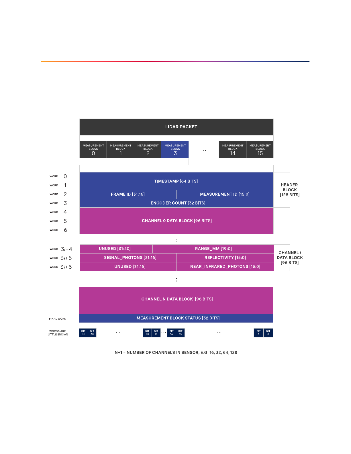
12 LidarPacketFormatUpdate
Starting infirmwarev2.0.0,all sensors with the same number ofchannelshavethe same data structureandsamemaximumdatarate. Priortov2.0.0,allsensors,regardlessoftheirnumberofchannels,
hadthe same data rate.
If you have either a Gen 1 OS1-16 or Gen 1 OS1-32, upon upgrading to firmware v2.0.0,you will see a
dropin data rate. Pleaserefer tothe diagram below fora visualization of lidarpacket structure.
Priorto to v2.0.0,all sensors, regardlessof number of channels, had a fixed number of datablocksin
their lidar packets. In v2.0.0,the number of data blocks in a sensor’s Measurement Block is equal to
thenumber ofchannels ithas. Customerswith Gen1OS1-16 orGen 1OS1-32willsee a75% and50%
respectivedrop indatarate due tounused data blocks beingomittedfrom the sensoroutput.
78
Page 79

Thesecustomerswill also see a change in theoutput of theTCP command get_beam_intrinsics. Previously,thebeam_azimuth_angles and beam_altitude_angles outputarray was paddedwith zeros sothat
theywere alwaysof length64,regardless ofthe number ofchannelsin that sensor. Now,thepadded
zerosaredroppedso thatthe lengthsof botharraysare equaltonumber ofchannel inthe sensore.g.
all32-channel sensorswill havebeam_azimuth_angles and beam_altitude_angles outputarrays oflength
32on v2.0.0and beyond.
TheTCPcommandget_lidar_data_format canalsobeusefulininterprettingthelidardataformatstructure:
columns_per_frame: Numberofdatacolumnsperframe. Thiscanbe512,1024,or2048,depending
uponthe set lidar mode.
columns_per_packet: Numberof Measurement Blockscontained in a singlelidarpacket. In v2.0.0
andearlier, this is16.
pixel_shift_by_row: Offset in terms of pixel count. Can be used to destagger image. Varies by
lidarmode. Length of thisarrayis equal tothenumber of channels ofthesensor.
pixels_per_column: Numberof channels of thesensor.
column_window: Indices of active columns of data in the sensor. These bounds will change when
acustom azimuth windowisused.
Pleaserefer to Data Rates section to compare maxdatarates and the Lidar Data PacketSize Calcu-
lation table to comparelidarpacket sizes ofallsensors on firmwarev2.0.0.
79
Page 80
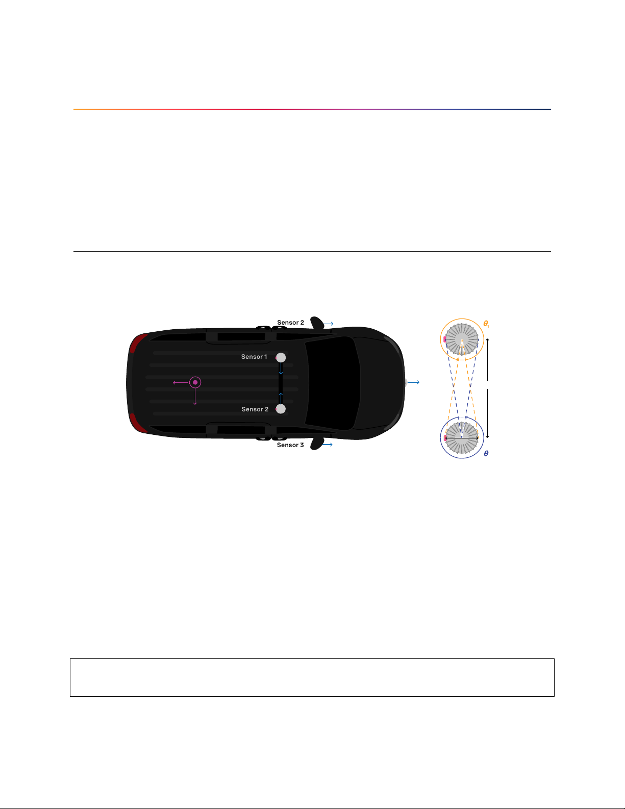
13 CrosstalkMitigationTutorial
Sensor 3
270°
Sensor 2
90°
Sensor 1
180°
90°
0° 180°
270°
270°
Sensor 1
90°
Sensor 2
0°
180°
270°
90°
Sensor 1
l
d
Sensor 2
X Z
Y
Inter-sensorcrosstalk occurswhen twosensorsare operatingclose together andtheyinterpret each
other’slaser pulses astheirown. Mitigating crosstalk betweentwo sensorsis a two stepprocess:
1) Phaselockthetwo sensors
2) Setazimuthwindowon eachsensorsothattheydon’t senddata whenthey arepointingateach
other
13.1 Two Sensor Example
In this example below, we are trying to mitigate inter-sensor crosstalk between Sensor 1 and Sensor
2 on the car. Bothof their connectors are facing towards the back of the car. TheLidar Coordinate
Frameis printed ontheback of the vehicleforreference.
Firstand foremost, placing a physical barrier between the two sensors is the best option to mitigate
cross talk in this example and most scenarios. If this is not possible, we can use the phase locking
feature to eliminate the problem. Crosstalk only occurs when one sensor shines its lasers into the
window of another sensor. The goal of phase locking is to force the sensors to point at each other
simultaneously so that crosstalk occurs when sensors aren’t generating important data about the
environment.
1a) Time synchronize the two sensors via an external source. Seethe Time Synchronization section
formore detailsontime synchronizing sensorswithan external GPS orviaPTP.
1b)Phaselockboth sensorssuch thattheypoint directlyat each otherat thesametime. In thiscase,
wewantSensor1tobepointingat90°atthesametimethatSensor2ispointingat270°. Theexample
netcatconsole output wouldlooklike below:
→
// set Sensor 1 to phase lock at 90°
$ nc sensor1_hostname 7501
set_config_param phase_lock_enable true
80
(continuesonnextpage)
Page 81

(continuedfrompreviouspage)
set_config_param
set_config_param phase_lock_offset 90000
set_config_param
reinitialize
reinitialize
save_config_params
save_config_params
// set Sensor 2 to phase lock at 270°
$ nc sensor2_hostname 7501
set_config_param phase_lock_enable true
set_config_param
set_config_param phase_lock_offset 270000
set_config_param
reinitialize
reinitialize
save_config_params
save_config_params
2) Setanazimuthwindowforbothsensors. Inthiscase,theregionofinterestforSensor1is θ1and
theregion of interestfor Sensor 2isθ
→
Thecalculation for θ1andθ2isas follows:
Inthiscase,ifthetwosensorswereplacedadistanceof100mmapart,360◦− 2 · arctan
◦
282
Wewantto setazimuth windowof size 282° for thetwo sensors, so that they do not send data in the
78° where they would point at each other. Sensor1’s azimuth window is the 282° centered around 270°.
Sensor2’sregionof interestisthe 282°centered around 90°.
2
θ1= θ2= 360
◦
− 2 · arctan
d
l
81
= 360◦− 78◦=
1000
// Sensor 1's azimuth window starts at 129° and follows the CCW direction to end at 51°
$ nc sensor1_hostname 7501
set_config_param azimuth_window [129000, 51000]
set_config_param
reinitialize
reinitialize
save_config_params
save_config_params
// Sensor 2's azimuth window starts at 309° and follows the CCW direction to end at 231°
$ nc sensor2_hostname 7501
set_config_param azimuth_window [309000, 231000]
set_config_param
reinitialize
reinitialize
save_config_params
save_config_params
81
Page 82

ProductLine Diameter
Atwindow Atbase includingfins
OS0and OS1 (Gen1and Gen2) 81mm 88mm
OS2 111mm 121 mm
82
Page 83

14 Drivers
Thelatest driver resourcesfor all Oustersensors are foundat www.ouster.com/resources
14.1 OpenSourceDrivers
Ourlatest open sourcedriversinclude:
ouster_client - an example C++client for Oustersensors
ouster_viz - a basic visualizerforOuster sensors
ouster_ros - a driver containingexampleROS nodes forpublishingpoint cloud messages
14.2 OusterStudio
Thelatest Ouster Studiovisualizercan be used torecord and playback.pcaprecordings.
83
Page 84

15 PTPQuickstartGuide
There are many configurations fora PTP network, this quick start guide aims to cover the basics by
using Ubuntu 18.04 as an example. It provides configuration settings for a commercial PTP grandmasterclock and also provides directions on setting up a Linux computer (Ubuntu 18.04)to function
asa PTP grandmaster.
Thelinuxptp projectprovidesa suiteof PTPtoolsthat canbeused toserveas a PTPmaster clockfor
alocal network ofsensors.
15.1 Assumptions
Commandline Linux knowledge (e.g.,package management, commandlinefamiliarity,etc.).
Ethernetinterfaces that support hardwaretimestamping.
Ubuntu18.04 is assumedforthis tutorial, butanymodern distribution should suffice.
Knowledgeof systemdserviceconfigurationand management.
Familiaritywith Linux permissions.
15.2 PhysicalNetworkSetup
Ensure the Ouster sensor is connected to the PTP master clock with at most one network switch.
IdeallythesensorshouldbeconnecteddirectlytothePTPgrandmaster. Alternatively,asimplelayer-2
gigabitEthernetswitchwillsuffice. Multipleswitchesarenot recommendedandwilladdunnecessary
jitter.
15.2.1 ThirdPartyGrandmaster Clock
A dedicated grandmaster clock should be used for the highest absolute accuracy often with a GPS
receiver.
Itmust be configured withthefollowing parameterswhich match thelinuxptp client defaults:
Transport: UDP IPv4
DelayMechanism: E2E
SyncMode: Two-Step
AnnounceInterval: 1 - sent every2 seconds
SyncInterval: 0 - sent every1 second
DelayRequest Interval: 0 -sentevery 1 second
84
Page 85

Formore settings, review the port_data_set field returned from the sensor’sHTTP system/time/ptp interface.
15.2.2 Linux PTP GrandmasterClock
AnalternativetoanexternalgrandmasterPTPclockistorunalocalLinuxPTPmasterclockifaccuracy
allows. Thisisoftenimplementedonavehiclecomputerthatinterfacesdirectlywiththelidarsensors.
Thissection outlines how toconfigure a masterclock.
85
Page 86

15.3 ExampleNetworkSetup
This section assumes the following network setup as it has elements of a local master clock andthe
optionfor an upstreamPTP time source.
+-------------------------------------+
| Ubuntu 18.04 System |
| * 2x Intel i210 Ethernet Interfaces |
| * Linux PTP service |
| |
| eno1 eno2 |
+-------+---------------------+-------+
| |
+-------+-------+ +--------+------+
| Trimble GM100 | | + +
| GPS -> PTP | | Ouster OS1 | |
| grandmaster | | | |
| (optional) | | | |
+---------------+ +---------------- |
+--------------- +
The focus is on configuring the Linux PTP service to serve a common clock to all the downstream
OusterOS1 sensors usingtheLinux system timefromthe Ubuntu host machine.
Optionally,agrandmasterclock can beaddedto discipline the systemtime of the Linuxhost.
15.4 InstallingNecessary Packages
Severalpackagesareneeded for PTPfunctionality and verification:
linuxptp - Linux PTP packagewith the followingcomponents:
ptp4l daemon to manage hardwareand participate as aPTPnode
phc2sys to synchronize the Ethernet controller’s hardware clock to the Linux system clock
orshared memory region
pmc to query the PTPnodes on the network.
chrony - A NTP and PTP time synchronization daemon. It can be configured to listen to both
NTPtime sources viathe Internet andaPTP masterclock such as oneprovided a GPSwith PTP
support. Thiswillvalidate the time configurationmakes sense givenmultiple time sources.
ethtool - A tool toquery the hardware anddriver capabilities of agivenEthernet interface.
$ sudo apt update
...
Reading package lists... Done
Building dependency tree
Reading state information... Done
$ sudo apt install linuxptp chrony ethtool
Reading package lists... Done
(continuesonnextpage)
86
Page 87

(continuedfrompreviouspage)
Building dependency tree
Reading state information... Done
The following NEW packages will be installed:
chrony ethtool linuxptp
0 upgraded, 3 newly installed, 0 to remove and 29 not upgraded.
Need to get 430 kB of archives.
After this operation, 1,319 kB of additional disk space will be used.
Get:1 http://us.archive.ubuntu.com/ubuntu bionic/main amd64 ethtool amd64 1:4.15-0ubuntu1 [114 kB]
Get:2 http://us.archive.ubuntu.com/ubuntu bionic/universe amd64 linuxptp amd64 1.8-1 [112 kB]
Get:3 http://us.archive.ubuntu.com/ubuntu bionic-updates/main amd64 chrony amd64 3.2-4ubuntu4.2 [203 kB]
Fetched 430 kB in 1s (495 kB/s)
Selecting previously unselected package ethtool.
(Reading database ... 117835 files and directories currently installed.)
Preparing to unpack .../ethtool_1%3a4.15-0ubuntu1_amd64.deb ...
Unpacking ethtool (1:4.15-0ubuntu1) ...
Selecting previously unselected package linuxptp.
Preparing to unpack .../linuxptp_1.8-1_amd64.deb ...
Unpacking linuxptp (1.8-1) ...
Selecting previously unselected package chrony.
Preparing to unpack .../chrony_3.2-4ubuntu4.2_amd64.deb ...
Unpacking chrony (3.2-4ubuntu4.2) ...
Setting up linuxptp (1.8-1) ...
Processing triggers for ureadahead (0.100.0-20) ...
ureadahead will be reprofiled on next reboot
Setting up chrony (3.2-4ubuntu4.2) ...
Processing triggers for systemd (237-3ubuntu10.13) ...
Processing triggers for man-db (2.8.3-2ubuntu0.1) ...
Setting up ethtool (1:4.15-0ubuntu1) ...
15.5 EthernetHardwareTimestamp Verification
Identifythe ethernet interfacetobe used onthe client (Linux) machine, e.g.,eno1. Run the eth-
toolutility and query thisnetworkinterface forsupportedcapabilities.
Outputof ethtool -T forafunctioning Intel i210 Ethernetinterface:
$ sudo ethtool -T eno1
Time stamping parameters for eno1:
Capabilities:
hardware-transmit (SOF_TIMESTAMPING_TX_HARDWARE)
software-transmit (SOF_TIMESTAMPING_TX_SOFTWARE)
hardware-receive (SOF_TIMESTAMPING_RX_HARDWARE)
software-receive (SOF_TIMESTAMPING_RX_SOFTWARE)
software-system-clock (SOF_TIMESTAMPING_SOFTWARE)
hardware-raw-clock (SOF_TIMESTAMPING_RAW_HARDWARE)
PTP Hardware Clock: 0
Hardware Transmit Timestamp Modes:
off (HWTSTAMP_TX_OFF)
on (HWTSTAMP_TX_ON)
Hardware Receive Filter Modes:
none (HWTSTAMP_FILTER_NONE)
(continuesonnextpage)
87
Page 88

(continuedfrompreviouspage)
all (HWTSTAMP_FILTER_ALL)
15.6 Configurations
15.6.1 Configuring ptp4l for Multiple Ports
OnaLinuxsystemwith multipleEthernetports(i.e. Inteli210)ptp4l needstobeconfiguredtosupport
allof them.
Modify/etc/linuxptp/ptp4l.conf and append the following,replacingeno1 and eno2 with the appropriateinterface names:
boundary_clock_jbod 1
[eno1]
[eno2]
Thedefault systemdservicefile forUbuntu 18.04 attemptsto use theeth0 address on thecommand
line. Override systemd service file so that the configuration file is used instead of hard coded in the
servicefile.
Createa systemddrop-in directory tooverride the systemservicefile:
$ sudo mkdir -p /etc/systemd/system/ptp4l.service.d
Createa file at/etc/systemd/system/ptp4l.service.d/override.conf with the followingcontents:
[Service]
ExecStart=
ExecStart=/usr/sbin/ptp4l -f /etc/linuxptp/ptp4l.conf
Restartthe ptp4l service so the changetakes effect:
$ sudo systemctl daemon-reload
$ sudo systemctl restart ptp4l
$ sudo systemctl status ptp4l
* ptp4l.service - Precision Time Protocol (PTP) service
Loaded: loaded (/lib/systemd/system/ptp4l.service; enabled; vendor preset: enabled)
Drop-In: /etc/systemd/system/ptp4l.service.d
└─override.conf
Active: active (running) since Wed 2019-03-13 14:38:57 PDT; 3s ago
Docs: man:ptp4l
Main PID: 25783 (ptp4l)
Tasks: 1 (limit: 4915)
CGroup: /system.slice/ptp4l.service
└─25783 /usr/sbin/ptp4l -f /etc/linuxptp/ptp4l.conf
Mar 13 14:38:57 leadlizard ptp4l[25783]: [590188.756] port 1: INITIALIZING to LISTENING on INITIALIZE
Mar 13 14:38:57 leadlizard ptp4l[25783]: [590188.756] driver changed our HWTSTAMP options
Mar 13 14:38:57 leadlizard ptp4l[25783]: [590188.756] tx_type 1 not 1
(continuesonnextpage)
88
Page 89

(continuedfrompreviouspage)
Mar 13 14:38:57 leadlizard ptp4l[25783]: [590188.756] rx_filter 1 not 12
Mar 13 14:38:57 leadlizard ptp4l[25783]: [590188.756] port 2: INITIALIZING to LISTENING on INITIALIZE
Mar 13 14:38:57 leadlizard ptp4l[25783]: [590188.757] port 0: INITIALIZING to LISTENING on INITIALIZE
Mar 13 14:38:57 leadlizard ptp4l[25783]: [590188.757] port 1: link up
Mar 13 14:38:57 leadlizard ptp4l[25783]: [590188.757] port 2: link down
Mar 13 14:38:57 leadlizard ptp4l[25783]: [590188.757] port 2: LISTENING to FAULTY on FAULT_DETECTED (FT_
,→UNSPECIFIED)
Mar 13 14:38:58 leadlizard ptp4l[25783]: [590189.360] port 1: new foreign master 001747.fffe.700038-1
Theabovesystemctl status ptp4l console output shows systemdcorrectlyread the override file createdearlier beforestartingseveral secondsafterthe restart command.
Thelogoutputshowsthatagrandmasterclockhasbeendiscoveredonport1(eno1)andport2(eno2)is
currentlydisconnectedand in thefaulty stateas expected. Inthe testnetworkaTrimbleThunderbolt
PTPGM100 Grandmaster Clockis attached on eno1.
Logscan be monitored(i.e. followed)likeso:
$ journalctl -f -u ptp4l
-- Logs begin at Fri 2018-11-30 06:40:50 PST. -Mar 13 14:51:37 leadlizard ptp4l[25783]: [590948.224] master offset -17 s2 freq -25963 path delay
,→ 14183
Mar 13 14:51:38 leadlizard ptp4l[25783]: [590949.224] master offset -13 s2 freq -25964 path delay
,
14183
→
Mar 13 14:51:39 leadlizard ptp4l[25783]: [590950.225] master offset 35 s2 freq -25920 path delay
,→ 14192
Mar 13 14:51:40 leadlizard ptp4l[25783]: [590951.225] master offset -59 s2 freq -26003 path delay
,→ 14201
Mar 13 14:51:41 leadlizard ptp4l[25783]: [590952.225] master offset -24 s2 freq -25986 path delay
,→ 14201
Mar 13 14:51:42 leadlizard ptp4l[25783]: [590953.225] master offset -39 s2 freq -26008 path delay
,→ 14201
Mar 13 14:51:43 leadlizard ptp4l[25783]: [590954.225] master offset 53 s2 freq -25928 path delay
,→ 14201
Mar 13 14:51:44 leadlizard ptp4l[25783]: [590955.226] master offset -85 s2 freq -26050 path delay
,→ 14207
Mar 13 14:51:45 leadlizard ptp4l[25783]: [590956.226] master offset 127 s2 freq -25863 path delay
,→ 14207
Mar 13 14:51:46 leadlizard ptp4l[25783]: [590957.226] master offset 9 s2 freq -25943 path delay
,→ 14208
Mar 13 14:51:47 leadlizard ptp4l[25783]: [590958.226] master offset -23 s2 freq -25973 path delay
,→ 14208
Mar 13 14:51:48 leadlizard ptp4l[25783]: [590959.226] master offset -61 s2 freq -26018 path delay
,→ 14190
Mar 13 14:51:49 leadlizard ptp4l[25783]: [590960.226] master offset 69 s2 freq -25906 path delay
,→ 14190
Mar 13 14:51:50 leadlizard ptp4l[25783]: [590961.226] master offset -73 s2 freq -26027 path delay
,→ 14202
Mar 13 14:51:51 leadlizard ptp4l[25783]: [590962.226] master offset 19 s2 freq -25957 path delay
,→ 14202
Mar 13 14:51:52 leadlizard ptp4l[25783]: [590963.226] master offset 147 s2 freq -25823 path delay
,→ 14202
...
89
Page 90

15.6.2 Configuringptp4l as a Local MasterClock
TheIEEE-1588BestMasterClockAlgorithm(BMCA)willselectagrandmasterclockbasedonanumber
ofmasters. Inmostnetworksthereshouldbeonlyasinglemaster. IntheexamplenetworktheUbuntu
machinewillbe configuredwitha non-defaultclockClass soitsoperationqualifiesitto wintheBMCA.
Replace the default value with a lower clock class (higher priority) and restart linuxptp. Edit /etc/
linuxptp/ptp4l.conf and comment out the defaultclockClass value and insert a linesetting it 128.
#clockClass 248
clockClass 128
Restartptp4l so the configurationchangetakes effect.
$ sudo systemctl restart ptp4l
Thiswillconfigureptp4l to advertise a master clock on eno2 as a clock that will win the BMCA for an
OusterOS1 sensor.
However, the ptp4l service is only advertising the Ethernet controller’s PTP hardware clock, not the
Linuxsystem time asisoftenexpected.
15.6.3 Configuring phc2sys toSynchronize the System Timeto thePTP Clock
To synchronize the Linux system time to the the PTP hardware clock the phc2sys utility needs to be
run. Thefollowing configuration will tell phc2sys to take the Linux CLOCK_REALTIME and write that time
tothe PTP hardwareclock in the Ethernet controllerforeno2. These interfaces arethenconnected to
PTPslavessuchas Ouster OS1 sensors.
Createa systemddrop-in directory tooverride the systemservicefile:
$ sudo mkdir -p /etc/systemd/system/phc2sys.service.d
Createa file at/etc/systemd/system/phc2sys.service.d/override.conf with the followingcontents:
[Service]
ExecStart=
ExecStart=/usr/sbin/phc2sys -w -s CLOCK_REALTIME -c eno2
Note: Ifmultiple interfaces need to be synchronized from CLOCK_REALTIME then multipe instances of
thephc2sys service need to berun as it only acceptsa single slave(i.e. -c) argument.
Restartthe phc2sys service so the changetakes effect:
$ sudo systemctl daemon-reload
$ sudo systemctl restart phc2sys
$ sudo systemctl status phc2sys
90
Page 91

15.6.4 ConfiguringChrony to Set SystemClock UsingPTP
AnupstreamPTPgrandmasterclock(e.g.,aGPSdisciplinedPTPclock)canbeusedtosetthesystem
time if precise absolute time is neededforsensor data. Chrony is a Linux time service that can read
from NTP and PTP and set the Linux system time using the most accurate source available. With a
properfunctioningPTPgrandmasterthePTPtimesourcewillbeselectedandtheerrorfromthepublic
timeserverscan bereviewed.
The following phc2shm service will synchronize the time from eno1 (wherethe external grandmaster
isattached) to the systemclock.
Createa file named/etc/systemd/system/phc2shm.service with the followingcontents:
# /etc/systemd/system/phc2shm.service
[Unit]
Description=Synchronize PTP hardware clock (PHC) to NTP SHM
Documentation=man:phc2sys
After=ntpdate.service
Requires=ptp4l.service
After=ptp4l.service
[Service]
Type=simple
ExecStart=/usr/sbin/phc2sys -s eno1 -E ntpshm -w
[Install]
WantedBy=multi-user.target
Thenstartthe newly createdservice and check that itstarted.
$ sudo systemctl start phc2shm
$ sudo systemctl status phc2shm
Addthe PTPtimesource tothe chrony configurationwhich will readthe shared memoryregionmanagedby the phc2shm service createdabove.
Appendthe followingtothe /etc/chrony/chrony.conf file:
refclock SHM 0 poll 1 refid ptp
Restartchrony so theupdatedconfiguration file takeseffect:
$ sudo systemctl restart chrony
Afterwaiting a minuteforthe clock tosynchronize, reviewthe chrony clienttimingaccuracy:
$ chronyc tracking
Reference ID : 70747000 (ptp)
Stratum : 1
Ref time (UTC) : Thu Mar 14 02:22:58 2019
System time : 0.000000298 seconds slow of NTP time
Last offset : -0.000000579 seconds
RMS offset : 0.001319735 seconds
(continuesonnextpage)
91
Page 92

Frequency : 0.502 ppm slow
Residual freq : -0.028 ppm
Skew : 0.577 ppm
Root delay : 0.000000001 seconds
Root dispersion : 0.000003448 seconds
Update interval : 2.0 seconds
Leap status : Normal
$ chronyc sources -v
210 Number of sources = 9
.-- Source mode '^' = server, '=' = peer, '#' = local clock.
/ .- Source state '*' = current synced, '+' = combined , '-' = not combined,
| / '?' = unreachable, 'x' = time may be in error, '~' = time too variable.
|| .- xxxx [ yyyy ] +/- zzzz
|| Reachability register (octal) -. | xxxx = adjusted offset,
|| Log2(Polling interval) --. | | yyyy = measured offset,
|| \ | | zzzz = estimated error.
|| | | \
MS Name/IP address Stratum Poll Reach LastRx Last sample
===============================================================================
#* ptp 0 1 377 1 +27ns[ +34ns] +/- 932ns
^- chilipepper.canonical.com 2 6 377 61 -482us[ -482us] +/- 99ms
^- pugot.canonical.com 2 6 377 62 -498us[ -498us] +/- 112ms
^- golem.canonical.com 2 6 337 59 -467us[ -468us] +/- 95ms
^- alphyn.canonical.com 2 6 377 58 +957us[ +957us] +/- 95ms
^- legacy13.chi1.ntfo.org 3 6 377 62 -10ms[ -10ms] +/- 178ms
^- tesla.selinc.com 2 6 377 128 +429us[ +514us] +/- 42ms
^- io.crash-override.org 2 6 377 59 +441us[ +441us] +/- 58ms
^- hadb2.smatwebdesign.com 3 6 377 58 +1364us[+1364us] +/- 99ms
(continuedfrompreviouspage)
Notethatthe Reference ID matchestheptp refidfromthe chrony.conffileandthatthesourcesoutput
shows the ptp reference id as selected (signified by the * state in the second column). Additionally,
theNTP time sources showa small relativeerrorto the highaccuracyPTP time source.
Inthis case the PTPgrandmasteris properlyfunctioning.
Ifthis error is large,chronywill select theNTPtime sources and mark thePTPtime source as invalid.
This typically signifies that something is mis-configured with the PTPgrandmasterupstream of this
deviceor the linuxptp configuration.
92
Page 93

15.7 VerifyingOperation
If the PTP grandmaster was just setup and configured, it’srecommended topowercyclethe sensor.
The sensor will then jump to the correct time instead of slowly easing in the time adjustment which
willtake time ifthegrandmaster initially setthesensor to the wrongtime.
15.7.1 HTTP API
Thesensor can be queried forthe state ofitslocal PTP service throughthe HTTP system/time/ptp.
JSONresponse fields tocheck:
parent_data_set.grandmaster_identity should list the identity ofthe local grandmaster
port_data_set.port_state should be SLAVE
15.7.2 LinuxPTPPMC Tool
The sensor will respond to PTP management messages. The linuxptp pmc (see man pmc) utility can be
usedto query all PTPdevices on the localnetwork.
Onthe Linux host forthe pmc utility tocommunicatewith then run thefollowing command:
$ sudo pmc 'get PARENT_DATA_SET' 'get CURRENT_DATA_SET' 'get PORT_DATA_SET' 'get TIME_STATUS_NP' -i eno2
sending: GET PARENT_DATA_SET
sending: GET CURRENT_DATA_SET
sending: GET PORT_DATA_SET
sending: GET TIME_STATUS_NP
bc0fa7.fffe.c48254-1 seq 0 RESPONSE MANAGEMENT PARENT_DATA_SET
parentPortIdentity ac1f6b.fffe.1db84e-2
parentStats 0
observedParentOffsetScaledLogVariance 0xffff
observedParentClockPhaseChangeRate 0x7fffffff
grandmasterPriority1 128
gm.ClockClass 6
gm.ClockAccuracy 0x21
gm.OffsetScaledLogVariance 0x4e5d
grandmasterPriority2 128
grandmasterIdentity 001747.fffe.700038
bc0fa7.fffe.c48254-1 seq 1 RESPONSE MANAGEMENT CURRENT_DATA_SET
stepsRemoved 2
offsetFromMaster 613554162.0
meanPathDelay 117977.0
bc0fa7.fffe.c48254-1 seq 2 RESPONSE MANAGEMENT PORT_DATA_SET
portIdentity bc0fa7.fffe.c48254-1
portState LISTENING
logMinDelayReqInterval 0
peerMeanPathDelay 0
logAnnounceInterval 1
announceReceiptTimeout 3
logSyncInterval 0
(continuesonnextpage)
93
Page 94

delayMechanism 1
logMinPdelayReqInterval 0
versionNumber 2
bc0fa7.fffe.c48254-1 seq 3 RESPONSE MANAGEMENT TIME_STATUS_NP
master_offset 613554162
ingress_time 0
cumulativeScaledRateOffset +0.000000000
scaledLastGmPhaseChange 0
gmTimeBaseIndicator 0
lastGmPhaseChange 0x0000'0000000000000000.0000
gmPresent true
gmIdentity 001747.fffe.700038
15.7.3 TestedGrandmaster Clocks
TrimbleThunderbolt PTPGM100 GrandmasterClock
Firmwareversion: 20161111-0.1.4.0, November 11 2016 15:58:25
PTPconfiguration:
→
> get ptp eth0
Enabled : Yes
Clock ID : 001747.fffe.700038-1
Profile : 1588
Domain number : 0
Transport protocol : IPV4
IP Mode : Multicast
Delay Mechanism : E2E
Sync Mode : Two-Step
Clock Class : 6
Priority 1 : 128
Priority 2 : 128
Multicast TTL : 0
Sync interval : 0
Del Req interval : 0
Ann. interval : 1
Ann. receipt timeout : 3
(continuedfrompreviouspage)
Ubuntu18.04 +Linux PTP as a masterclock
Inteli210 Ethernet interface
PCIhardware identifiers: 8086:1533 (rev 03)
Ubuntu18.04 kernelpackage: linux-image-4.18.0-16-generic
Ubuntu18.04 linuxptp package: linuxptp-1.8-1
94
Page 95

16 NetworkingGuide
16.1 Networking101
Thisguide will help you understandhowto quickly get connectedto your sensor to start doing great
thingswith it. Whentrying toconnect tothe sensor forthefirsttime thereare somebasics thatneed
toto be achievedfor successful communicationbetween the host machineand the sensor.
Weneed to ensure that the sensor receivesanIPaddressfrom the host machine so that we can talk
to it. This can be achieved with a few different methods such as DHCP, link-local, static IP. We also
needto ensure thatthesensor and the host machineare talking on thesamesubnet.
Once the sensor receives an IP address and is on the correct subnet we can talk to it using its hostname,os-991234567890.local, where 991234567890 isthesensor serial number.
Ifsomeof this terminologyisnewtoyou don’tfret,wehavedefined some of it for you. Hereis some
basicterminology thatwillhelp youdigestthe stepsandbe morefamiliarwith networkingin general.
IPv4Address Thisis the address that can be used to communicate with devices on a network. The
formatofanIPv4addressisasetoffouroctets,xxx.xxx.xxx.xxx withxxx beingintherange0-255.
Forexample,yourhostmachineEthernetportmayhaveanaddressof192.0.2.1 andyoursensor
mayhaveanaddress of 192.0.2.130.
DHCP(Dynamic Host Configuration Protocol)Server This is a server that may run on your host
machine,switch, orrouterwhich willservean IPv4addressto adevice that isconnectedto it. It
willensure that each deviceconnected will havea unique IPv4 addresson the network.
Link-localIPv4 Address These are the addresses that areself-assignedbetween the host machine
and a device connected to it in the absence of a DHCP server. They are only valid within the
networksegment that the host is connected to. The addresses lie within theblock169.254.0.0/
16 (169.254.0.0 - 169.254.255.255).
SubnetMask Thisdefines which bits of the IPv4 address are the network prefix and which are the
hostidentifiers. See the tablebelowfor an example.
Binary Form Decimal-dotnotation
IPaddress
Subnetmask
Networkprefix
Hostidentifier
Note: Subnetmask can beabbreviatewith thenumber of bitsthatapply to thenetworkprefix.
E.g. /24for 255.255.255.0or /16 for255.255.0.0.
11000000.00000000.00000010.10000010 192.0.2.130
11111111.11111111.11111111.00000000 255.255.255.0
11000000.00000000.00000010.00000000 192.0.2.0
00000000.00000000.00000000.10000010 0.0.0.130
95
Page 96

StaticIPv4 Address Thisis whenyouspecifythe addressesforthe hostmachine and/orconnected
deviceratherthanlettingthehostmachineself-assignorusingaDHCPserver. Forexample,you
may want to specify the host machine IPv4 address to be 192.0.2.100/24 and the sensor to be
192.0.2.200.
Hostname This is the more human readable name that comes with your sensor. The sensor’s host-
nameis os-991234567890.local, where 991234567890 isthe sensor serial number.
Note: The .local portion of the hostname denotes the local domain used in combination with
multicastDNS(mDNS).Itisemployedwhenusingthesensorinalocalnetworkenvironmentwith
supportingoperating systemservices. This means whenthe sensor isdirectly connectedto the
host machine or if the host machine and sensor are on thesame network connected through a
routeror switch. If you aretrying to connecttothe sensoronanother domain withasupporting
DHCP and DNS server configuration you should replace the .local with the domain the sensor
is on. For example, if the sensor is connected to a network with domain ouster-domain.com the
sensorwill be reachable onos-991234567890.ouster-domain.com.
16.2 Windows
ThefollowingstepshavebeentestedonWindows10. Thesensor’shostnameisos-991234567890.local,
where991234567890 is the sensorserialnumber.
16.2.1 Connecting the Sensor
1. Connectthesensorto an availableEthernet port on your hostmachineor router.
2. Thesensor will automatically obtain an IPaddresseither through link-local or DHCP (if preconfigured)depending on yournetworkconfiguration.
Note: It can take up to 60 seconds to obtain an IP address from the initial power-up of the
sensor.
16.2.2 The Sensor Homepage
1. Typeos-991234567890.local in the address barofyour browsertoview the sensorhomepage
Note: Ifyou are unable to load the sensor homepage, followthe steps in Determining the IPv4
Address of the Sensor to verifyyour sensor is onthenetwork and hasavalid IPv4 address.
96
Page 97

16.2.3 Determiningthe IPv4Address ofthe Sensor
1. Openacommandprompt on the hostmachineby pressing Win+Xand then A
2. Usethepingcommand to determinetheIPv4 address of thesensor
Command
ping -4 [sensor_hostname]
Example
C:\WINDOWS\system32>ping -4 os-991234567890.local
Note: If this command hangs you may need to go back and configure you interface to
link-localin the section Connecting the Sensor
Response
Pinging os-991234567890.local [169.254.0.123] with 32 bytes of data:
Reply from 169.254.0.123: bytes=32 time<1ms TTL=64
Reply from 169.254.0.123: bytes=32 time<1ms TTL=64
Reply from 169.254.0.123: bytes=32 time<1ms TTL=64
Reply from 169.254.0.123: bytes=32 time<1ms TTL=64
Ping statistics for 169.254.0.123:
Packets: Sent = 4, Received = 4, Lost = 0 (0% loss),
Approximate round trip times in milli-seconds:
Minimum = 0ms, Maximum = 0ms, Average = 0ms
Note: Inthisexample,yoursensorIPv4 addressis determinedto be169.254.0.123. If your
sensorIPv4 address is oftheform 169.254.x.x itisconnected via link-local.
3. You can also browsefor the sensor IPv4 addressusingdns-sd and the sensor hostname. Learn
moreabout this in Finding a Sensor with mDNS Service Discovery
Command
dns-sd -G v4 [sensor_hostname]
Example
C:\WINDOW\system32>dns-sd -G v4 os-991234567890.local
Response
Timestamp A/R Flags if Hostname Address TTL
14:22:46.897 Add 2 6 os-991234567890.local 169.254.0.123 120
Note: Inthisexample,yoursensorIPv4 addressis determinedto be169.254.0.123. If your
sensorIPv4 address is oftheform 169.254.x.x itisconnected via link-local.
97
Page 98

16.2.4 Determiningthe IPv4 Address of the Interface
1. Openacommandprompt by pressingWin+Xand thenA
2. ViewtheIPv4 address of yourinterfaces
Command
netsh interface ip show config
Example
C:\WINDOWS\system32>netsh interface ip show config
Response
Configuration for interface "Local Area Connection"
DHCP enabled: Yes
IP Address: 169.254.0.1
Subnet Prefix: 169.254.0.0/16 (mask 255.255.0.0)
InterfaceMetric: 25
DNS servers configured through DHCP: None
Register with which suffix: Primary only
WINS servers configured through DHCP: None
Configuration for interface "Loopback Pseudo-Interface 1"
DHCP enabled: No
IP Address: 127.0.0.1
Subnet Prefix: 127.0.0.0/8 (mask 255.0.0.0)
InterfaceMetric: 75
Statically Configured DNS Servers: None
Register with which suffix: Primary only
Statically Configured WINS Servers: None
Inthis example, your sensorisplugged into interface“LocalArea Connection”
YourhostIPv4addresswillbeon theline thatstartswith IPAddress: Inthiscase itis
169.254.0.1
Note: IfyourinterfaceIPv4addressisoftheform169.254.x.x,itisconnectedvialink-local
to the sensor. Thismeans that Windows self-assigned an IP address in the absence of a
DHCPserver.
16.2.5 Setting the Host Interfaceto DHCP
Usethis to set your interfaceto automatically obtain an IPaddressvia DHCP.This is useful for architecturesthat need tobe more plug andplay.
Setyour interfaceto DHCP
Command
98
Page 99

netsh interface ip set address ["Network Interface Name"] dhcp
Example withinterfacename "Local Area Connection"
C:\WINDOWS\system32>netsh interface ip set address "Local Area Connection" dhcp
Response blank
16.2.6 Settingthe Host Interfaceto Static IP
Usethis toset yourinterfacetobeassigned astaticIPv4 address. Thisis usefulforcontrollingtheIP
addressthat the sensor willbesending data to.
Setyour interfaceto static
Command
netsh interface ip set address name="Network Interface Name" static [IP address] [Subnet Mask]
,→[Gateway]
Example withinterfacename “Local AreaConnection” and IPv4 address192.0.2.1/24.
C:\WINDOWS\system32>netsh interface ip set address name="Local Area Connection" static
,→192.0.2.1/24
Note: The/24 is shorthand forSubnetMask = 255.255.255.0
Response blank
16.2.7 Finding a Sensor with mDNSService Discovery
ThesensorannouncesitspresenceonthenetworkusingMulticastDomainNameService(mDNS)with
aservice typenamed
_roger._tcp. Youcan useservicediscovery toolssuch asdns-sd (Windows/ma-
cOS)tofind all sensors connectedto the network.
Note: If your version of Windows does not have dns-sd on the command line you can install it by
downloadingthe Bonjour SDK forWindows (availablethrough Apple orSoftpedia)
1. Findallsensorsand their associatedservicetexton a network.
Command
dns-sd -Z [service type]
Example
C:\WINDOWS\system32> dns-sd -Z _roger._tcp
Response
99
Page 100

Browsing for _roger._tcp
; To direct clients to browse a different domain, substitute that domain in place of
,→'@'
lb._dns-sd._udp PTR @
; In the list of services below, the SRV records will typically reference dot-local
,→Multicast DNS names.
; When transferring this zone file data to your unicast DNS server, you'll need to
,→replace those dot-local
; names with the correct fully-qualified (unicast) domain name of the target host
,→offering the service.
_roger._tcp PTR Ouster\032Sensor\032
,→991234567890._roger._tcp
Ouster\032Sensor\032 991234567890._roger._tcp SRV 0 0 7501 os-991234567890.
,→local. ; Replace with unicast FQDN of target host
Ouster\032Sensor\032
,→991234567890" "fw=ousteros-image-prod-aries-v2.0.0-20200417193957"
991234567890._roger._tcp TXT
"pn=840-102145-B" "sn=
2. Browsefor the sensorIPv4address using dns-sd andthesensor hostname.
Command
dns-sd -G v4 [sensor_hostname]
Example
C:\WINDOWS\system32>dns-sd -G v4 os-991234567890.local
Response
Timestamp A/R Flags if Hostname Address TTL
14:22:46.897 Add 2 6 os-991234567890.local. 169.254.0.123 120
Note: Inthis example, your sensorIPv4 address is determinedto be 169.254.0.123
100
 Loading...