

Page 1
Operating Instructions
Precipitation gauge
OTT Pluvio2S
English
Page 2

We reserve the right to make technical changes and improvements without notice.
Page 3

Table of contents
1 Scope of supply 4
2 Order numbers 4
3 Introduction 5
3.1 Measured value output to the SDI-12 and RS-485 interfaces 7
3.2 Measured value output at pulse output 9
3.3 Graphic display of measured value output for different precipitation intensities 11
3.4 Orifice ring rim heater 12
4 Basic safety information 15
2
5 Installing the OTT Pluvio
5.1 Recommended cable types/maximum cable lengths 16
5.2 Required tools and equipment 17
5.3 Preparing the installation location 18
5.4 Preparing the base plate 19
5.5 Preparing the connection cable 20
5.6 Installing the base plate on the pedestal 22
5.7 Connecting the connection cable 23
5.8 Connecting the grounding cable 23
5.9 Aligning the base plate 24
5.10 Performing final work 25
S 16
6 SDI-12 commands and responses 29
6.1 Basic commands 29
6.2 Advanced SDI-12 commands 32
6.3 RS-485 command line mode (ASCII text retrieval) 35
7 Performing maintenance operations 36
7.1 Emptying the collecting bucket 36
7.2 Adding anti-freeze agent for winter operation 36
7.3 Performing the visual inspection 37
7.4 Additional checks in cases of defect 37
7.5 Troubleshooting/remedy 38
7.6 Performing the Guided Accuracy Test (check measurement) 42
8 Repair 44
9 Notes about the disposal of used units 44
10 Technical Data 45
Appendix A – Connecting the OTT Pluvio
2
A.1 Connecting the OTT Pluvio
A.2 Connecting the OTT Pluvio
S to an OTT netDL or OTT DuoSens via SDI-12 or RS-485 interface 47
2
S to an OTT netDL or OTT DuoSens via the pulse output 49
Appendix B – Dimensions of the OTT Pluvio
2
S to an OTT datalogger 47
2
S with pedestal and bottom plate 51
Appendix C – Dimensions of pedestal with bottom plate 52
Appendix D – Installing the anti-theft protection 53
Appendix E – Accessories/replacement parts 54
3
Page 4

1 Scope of supply
䊳
OTT Pluvio2S – Weighing precipitation gauge;
collecting area: 200 cm
Consisting of: base plate with weighing mechanism, bucket support,
collecting bucket, and pipe housing. With SDI-12, RS-485, and USB
interfaces (for servicing purposes). Additional pulse outputs for amount
of precipitation and status information.
Optionally available with additional internal orifice rim heater.
– Installation accessory kit
(6 hexagon bolts M 8 x 30;
3 Phillips screws M 5 x 35
1 8-wire screw terminal strip;
1 6-wire screw terminal strip;
3 cable ties 140 x 3.6;
1 Jumper
1 open-ended wrench, size: 10/13
– USB cable
SB connector type A to USB connector type B, 3 m
U
– Operating Instructions
– Factory acceptance test (FAT) certificate
2
; capacity: 400 mm of precipitation.
2 Order numbers
䊳
OTT Pluvio2S 70.030.002.9.0
䊳
OTT Pluvio2S incl. internal orifice ring heater 70.030.001.9.0
For accessories and replacement parts, refer to Appendix E
4
Page 5
3 Introduction
The OTT Pluvio2S precipitation gauge is used for automatic determination of the
meteorological intensity and amount of precipitation.
In contrast to conventional precipitation gauges, the OTT Pluvio
weighing principle. The OTT Pluvio
2
S reliably detects precipitation, whether liquid
or solid, by determining the weight of the collecting bucket. The OTT precipitation
gauge is characterized in particular by its low maintenance needs. This is achieved
by means of a high-capacity collecting bucket, the lack of a collection funnel as is
typical for tipping buckets, and the very robust design of the weighing mechanism.
A high-precision, stainless steel load cell, hermetically sealed against environmental
influences that remains stable over a long period, is used as the sensor element.
An integrated temperature sensor compensates for the temperature changes in the
weighing mechanism. The mechanical overload protection prevents damage to the
oad cell from forces in a vertical direction higher than permitted, e.g. when emp-
l
tying the collecting bucket.
2
S works using the
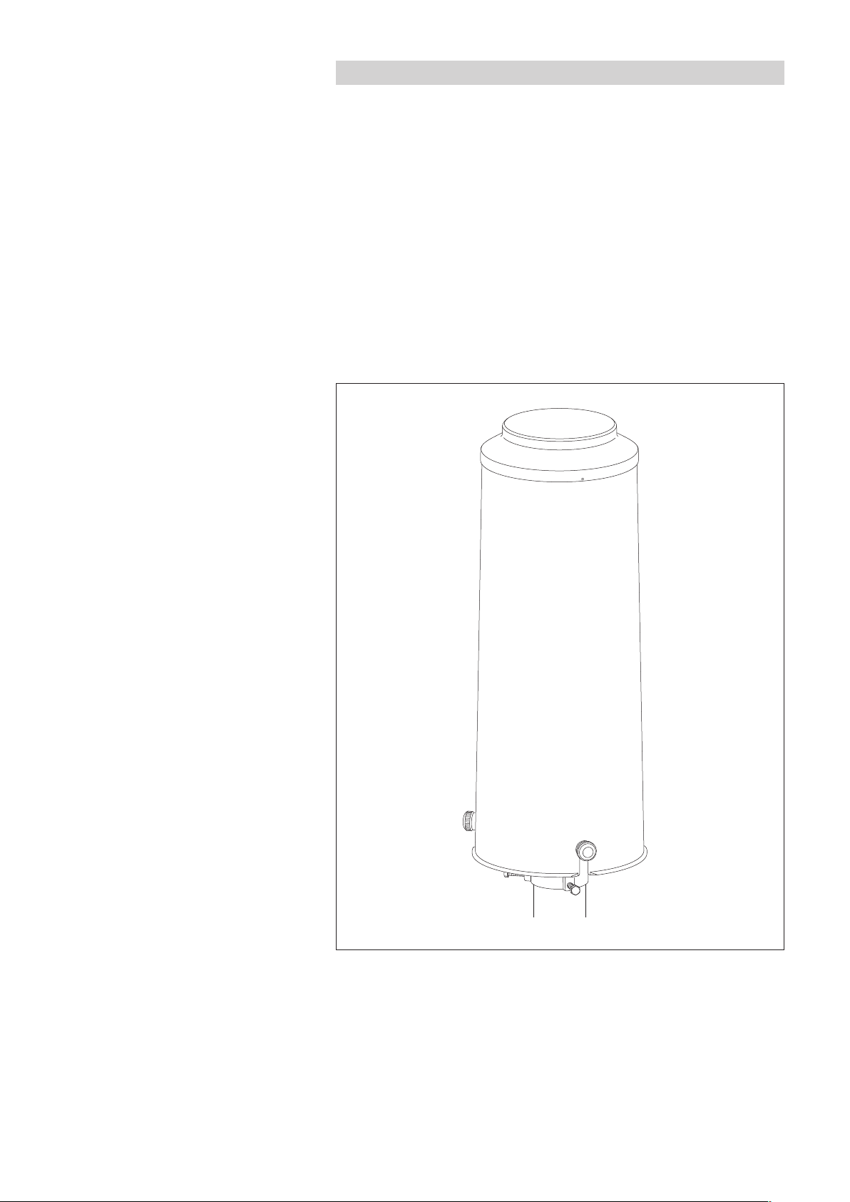
Fig. 1: OTT Pluvio2S precipitation gauge.
5
Page 6

Every 6 seconds, the precipitation gauge determines the weight of the collecting
bucket including its content using a resolution of 0.001 mm (= raw data). The
ifference between this measured value and the basic weight of the empty collect-
d
ing bucket gives the current bucket content.
special filter algorithm prevents incorrect measurement results in the process
A
from effects such as wind. The difference between the current bucket content and
the previous one gives the precipitation intensity in mm/min or mm/h.
These 6-second values for the precipitation intensity are added to the accumulated
precipitation amount (Accu total NRT – see below) by the OTT Pluvio
2
S.
Depending on the filter algorithm run, the measured values are available as
real-time and non-real-time values:
䊳
Real-time output (RT): The OTT Pluvio2S outputs the measurement result
for intensities greater than 0.1 mm/min within a minute after occurrence of
the precipitation event. Benefit: fast response time and precipitation output with
correct intensity.
䊳
Non-real-time output (NRT): The OTT Pluvio2S outputs the measurement
result 5 minutes after occurrence of the precipitation event. Benefit: more
precise output with correct precipitation volume.
All measured values can be retrieved via a serial SDI-12 and RS-485 interface.
In detail, these are:
䊳
Intensity RT
䊳
Accu RT/NRT (since the last measured value sample)
䊳
Accu NRT (since the last measured value sample)
䊳
Accu total NRT (since the last reset)
䊳
Bucket RT
䊳
Bucket NRT
䊳
Temperature of load cell
䊳
Status OTT Pluvio2S (since the last measured value sample)
2
The OTT Pluvio
S provides the precipitation values using a resolution of 0.001 mm.
Individual response thresholds of ≥ 0.03 mm are applied to these values within
one hour. A detailed description of the individual measured values can be found
in Chapter 3.1.
The OTT Pluvio
2
S uses two pulse outputs to output the amount of precipitation
RT/NRT (output #1) as well as the status information (output #2) in parallel. The
pulse factor may be selected: one pulse equals 0.05 mm, 0.1 mm, 0.2 mm,
0.5 mm or 1.0 mm of precipitation.
Parallel operation of serial interface and pulse output allows two dataloggers or
one datalogger and one PLC to be connected simultaneously.
2
The OTT Pluvio
S is installed to a 2" pedestal the bottom plate of which is mounted
to a concrete foundation. The standard installation height is 1 meter (height of the
orifice ring rim). Alternatively, 1.2 or 1.5 meters are possible.
After connecting the supply voltage, the OTT Pluvio
operation (➝ red LED is flashing, refer to Fig. 18). The OTT Pluvio
2
S automatically starts measuring
2
S is calibrated
in the factory. On site, no further calibration is necessary.
Any increases in weight greater than approx. 12 mm within 6 seconds are not output
as precipitation, as they exceed a natural level of precipitation. Thus, spurious increases
such as bucket changes or filling with anti-freeze are suppressed. Check measurements,
even with large reference weights (> 240 g), are possible using the values of Bucket RT
and Bucket NRT. The measured value sample is carried out in a joint data telegram with
multiple measured values. Individual samples with different intervals are not possible.
6
Page 7

For service purposes (test measurements, convenient setting of operating parameters and for an accuracy test) a USB interface has been provided. The particular
dvantage of this is: when using the USB interface, no separate power supply is
a
required.
Please note: After connecting the USB interface, the OTT Pluvio
2
S interrupts
communication on the serial interfaces!
The measuring system of the OTT Pluvio2 S prevents output of any incorrect
precipitation amount and does not output any increases in precipitation through
he interfaces after the following situations:
t
䊳
USB interface was connected (pipe housing removed)
䊳
Emptying (large reduction in weight) for approx. 5 minutes
䊳
Startup/power failure
for approx. 2 minutes
for approx. 5 minutes
The OTT test weight kit (accessory) is used to perform annual check measurements
(guided accuracy test) in conjunction with the OTT Pluvio
2
operating software.
3.1 Measured value output to the SDI-12 and RS-485 interfaces
䊳
Intensity RT
Moving precipitation growth over the last minute before the sampling interval
(measuring method acc. to WMO Guideline No. 8). This measured value is
particularly suited, for example, for the exact determination of intensity with heavy
precipitation and for alarm management, but not for daily and monthly totals.
Output delay: Real-time output (RT)
Units: mm/h · mm/min
inch/h · inch/min
Threshold: 0,1 mm/min · 6 mm/h
Sampling interval required: 1 minute
Storing interval required: 1 minute
Note: Larger sampling intervals always give the precipitation intensity of the minute
just before the sampling interval! For precipitation intensities of < 0.1 mm/min, the
OTT Pluvio
2
S sets the output value to zero. Thus, this output value may not be used
for accumulating single intensity values.
䊳
Accu RT-NRT
This value is a combination of real-time and non-real-time output. This value provides the benefit of faster RT output together with subsequent non-real-time output
delivering the maximum accuracy possible. It shows the accumulated amounts of
precipitation over the sampling interval. If the amount of precipitation exceeds the
threshold, the OTT Pluvio
2
S outputs the measurement result in real time. Otherwise, it collects the fine precipitation over a maximum of one hour and outputs the
measured value in non-real time. If the fine precipitation does not reach the
threshold within an hour, there will be no output. This measured value is similar to
the behaviour of a precipitation gauge with tipping bucket. This measured value is
particularly suited for daily or monthly totals and for alarm management.
Output delay: Real-time output (RT) for precipitation events
immediately exceeding the threshold, otherwise
non-real-time output (NRT).
Units: mm · inch
Threshold: 0.03 mm within an hour
7
Page 8

Recommended sampling interval: 1 minute (with simultaneous sampling of the
precipitation intensity)
ecommended storing interval: Any time between 1 minute and 24 hours. The
R
datalogger must total the individual measured
values using a summing function over the complete storing interval!
Note: Every interface polling resets the total amount values in the OTT Pluvio
to zero!
䊳
Accu NRT
This measured value outputs the sum of the correct amounts of precipitation over
the sampling interval with a fixed output delay of 5 minutes. Due to better filtering, this valuable provides a more precise precipitation sum. Fine precipitation is
col lected over a maximum of one hour and output after reaching the threshold. If
the fine precipitation does not reach the threshold within an hour, there will be no
output. This value is particularly suited for daily and monthly totals
Output delay: Non-real-time output (NRT)
Units: mm · inch
Threshold: 0.03 mm within an hour
Recommended sampling interval: 1 minute (with simultaneous sampling of the
precipitation intensity)
Recommended storing interval: Any time between 1 minute and 24 hours. The
datalogger must total the individual measured
values using a summing function over the complete storing interval!
Note: Every interface polling resets the total measured value in the OTT Pluvio
to zero. The 5 minute output delay provides the option for climatological databases
to apply a timestamp correction when necessary.
䊳
Accu total NRT
2
S
2
S
This measured value outputs the sum of the correct amounts of precipitation since
the last device start with a fixed output delay of 5 minutes. For this purpose, the
individual Accu NRT values are totalled (redundant sensor). This value is particularly
suited for daily or monthly totals as well as for tracking the plausibility of the Accu
NRT and Accu RT-NRT values. Benefit: No loss of the collected precipitation
amount values in case of temporarily disrupted data transfer.
Resetting this value is achieved
– by a separate SDI-12 reset command, or
– by switching the power supply on/off, or
– automatically if the measurement range (500 mm; 50 inch) is exceeded
Output delay: Non-real-time output (NRT)
Units: mm · inch
Threshold: 0.03 mm within an hour
Recommended sampling interval: 1 minute (with simultaneous sampling of the
precipitation intensity)
Recommended storing interval: Any time between 1 minute and 24 hours
(do not total/average measured values)
8
Page 9

䊳
Bucket RT
This value outputs the currently measured, unfiltered bucket content. It corresponds
to the measured weight raw data and is subjected to higher uncertainty with
regard to temperature and wind impact. The measured value is particularly suited
or quick reference measurements of the weighing mechanism and for determining
f
the current bucket level. Using this measured value for separately calculating the
amount of precipitation in an external datalogger is not reasonable!
Output delay: real-time output (RT)
Units: mm · inch
Resolution: 0.001 mm (1mm =^20 g)
ecommended sampling interval: 1 minute (with simultaneous sampling of the
R
precipitation intensity)
Recommended storing interval: any time between 1 minute and 24 hours
(possibly averaging over 10 minutes)
䊳
Bucket NRT
This value outputs the currently measured, filtered bucket content.
It corresponds to the filtered weight value and is subjected to uncertainty with
regard to temperature impact. The value is particularly suited for determining
the content of the bucket and for calculating the evaporation behaviour. Using
this measured value for separately calculating the amount of precipitation in an
external datalogger is not reasonable!
Output delay: non-real-time output (NRT)
Units: mm · inch
Resolution: 0.001mm (1mm =^20 g)
Recommended sampling interval: 1 minute (with simultaneous sampling of the
precipitation intensity)
Recommended storing interval: any time between 1 minute and 24 hours
䊳
Temperature of load cell
Internal temperature of the load cell for compensating for the temperature change.
This value is only relevant to internal purposes and generally differs from the current
ambient temperature by several °C.
Units : °C · °F
Recommended sampling interval: 1 minute (with simultaneous sampling of the
precipitation intensity)
Recommended storing interval: only as required (any time between 1 minute
and 24 hours)
3.2 Measured value output at pulse output
The OTT Pluvio
2
S uses two pulse outputs to output the amount of precipitation
RT/NRT (output #1) as well as the status information (output #2) in parallel.
Parallel operation of serial interface and pulse output allows two dataloggers
or one datalogger and one PLC to be connected simultaneously.
Electrical characteristics of the pulse and status outputs
Pulse ON contact closed
Pulse/pause ratio: 1:1
for 5 Hz =^100/100 ms
for 2 Hz =^250/250 ms
Contact design: non-bouncing, polarity independent, isolated
Current capacity, I
: ≤ 100 mA (short-circuit proof;
max
load cut-off at 200 mA)
Voltage, U
: ≤ 28 V
max
DC
9
Page 10
䊳
Pulse OUT mm/inch A
Pulse OUT mm/inch
B
Pulse OUT Status A
Pulse OUT Status B
1 2 34
I
max
: 100 mA*
U
m
ax
: 28 V
D
C
Terminals 2 + 4
Terminals 1 + 3
10 Ohm
Simplified schematic diagram
Detailed diagram
Ter mi na ls
internal optoelectronic relay
* short circuit protected; load cut-off at 200 mA
Pulse-Accu RT-NRT
This measured value is same as Accu RT-NRT. However, the threshold is determined by the resolution of the pulse output (0.05 mm · 0.1 mm · 0.2 mm · 0.5
mm · 1.0 mm).
he measured value is output as a pulse sequence using a rate of 5 Hz (default)
T
or 2 Hz (con figurable through the OTT Pluvio
2
S operating software via USB
interface).
Output delay: refer to Accu RT-NRT
Pulse factor (selectable): 0.05 mm · 0.1 mm · 0.2 mm · 0.5 mm · 1.0 mm
(1 mm =^20 · 10 · 5 · 2 · 1 Impulse(s))
Resolution: 0.05 mm · 0.1 mm · 0.2 mm · 0.5 mm · 1.0 mm
Recommended sampling interval: continuous pulse counting
Recommended storing interval: any time between 1 minute and 24 hours
䊳
Pulse status information
This measured value corresponds to the current bucket level and additionally
shows status information. Moreover, status information may be used as an
alive signal.
0 pulses/min system error, device or cable at the pulse output faulty
(output #2)
10 … 100 pulses/min 0 … 100 % of the approx. bucket level
120 pulses/min maintenance by means of operation through USB
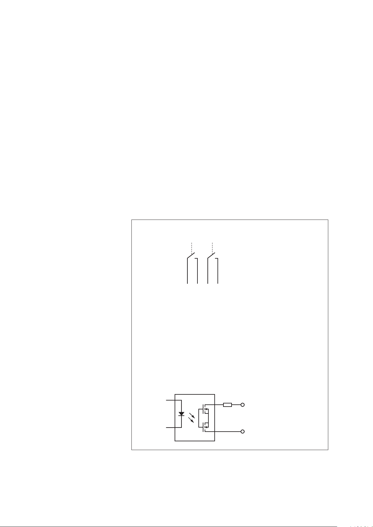
Fig. 2: Pulse output circuit diagram.
The locations of the terminals
are shown in Fig. 13.
Output #1: Terminals #1 and #2.
Output #2: Terminals #3 and #4.
10
Page 11
Please note:
Bucket RT
Bucket NRT
Intensity RT
Accu RT-NRT
Accu NRT
Accu total NRT
Fine precipitation
< 0,1 mm/min
Precipitation
≥
0,1 mm/min
Pulse-Accu RT-NRT
5
min
Threshold
0,001 mm
0
,001 mm
0,1 mm/min
0,03 mm
1)
0
,03 mm
1)
0,1 mm
2)
1)
within one hour
2)
adjustable
0,03 mm
1)
When the pulse outputs are connected to
OTT dataloggers ➝ no additional wiring is required to be made. You may
–
directly connect the pulse outputs to the pulse inputs of an OTT datalogger.
– Third-party datalogger ➝ external wiring at the pulse and status outputs must
be designed in such a way, that the limits for I
≤ 120 mA and U
max
max
will be kept in all operating conditions! Use a pull-up resistor as applicable!
3.3 Graphic display of measured value output for different precipitation intensities
≤ 28 V
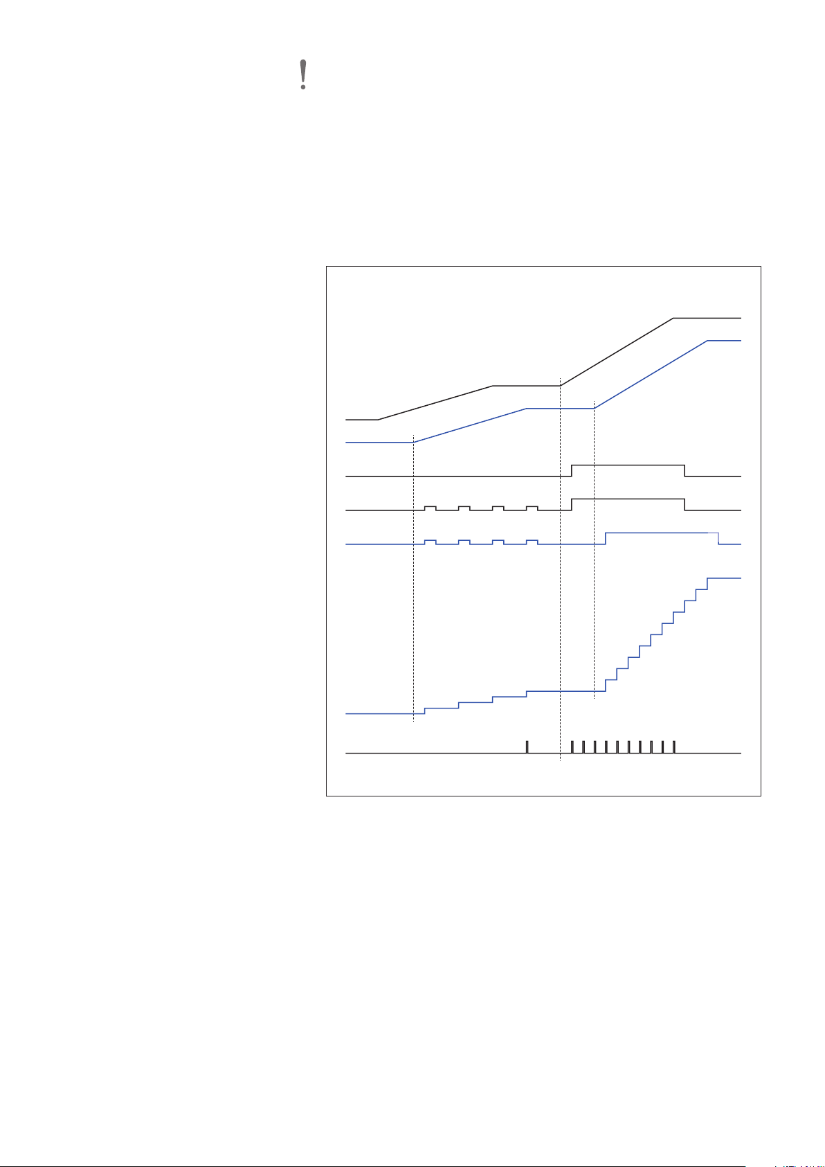
Fig. 3: Schematic display of measured
value output for different precipitation
values of the OTT Pluvio
2
S for fine
precipitation (< 0.1 mm/min) and
precipiation (≥ 0.1 mm/min).
Thresholds of the channels
are indicated on the right.
11
Page 12
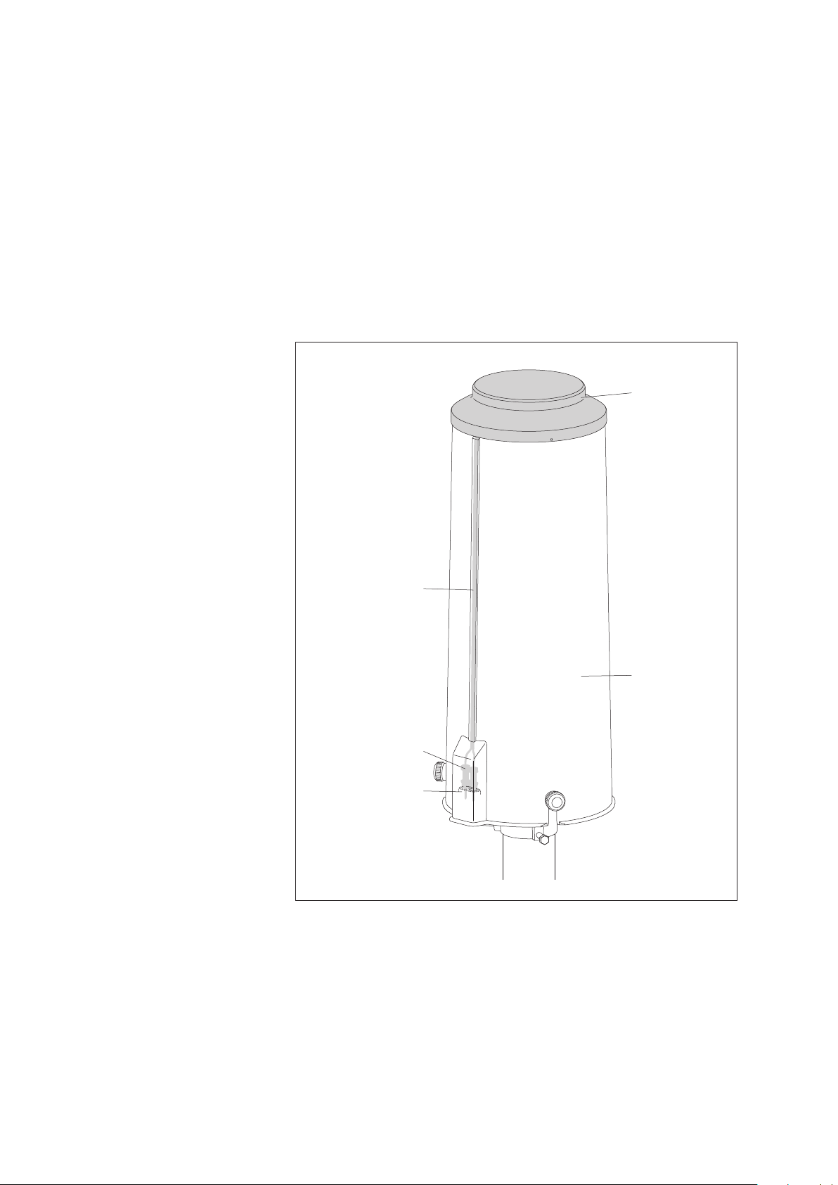
3.4 Orifice ring rim heater
Orifice rim
Pipe housing
Cable
Orifice rim heater
Plug contacts
Connector block
2
For the OTT Pluvio
S, an optional orifice rim heater is available. This heater
reliably keeps the orifice rim free of snow and ice at low ambient temperatures
(e.g. no snow or ice build-up). No snow will accumulate at the orifice rim.
The orifice rim heater consists of a ring-shaped heating element within the pipe
housing with temperature sensor and an electronic heater control module for con-
rolling and monitoring the heating function. The heater cable electrical connection
t
is established automatically via two plug contacts and a connector block once the
pipe housing is placed onto the base plate.
Only the orifice rim is heated to avoid unwanted losses caused by evaporation.
Therefore, the orifice rim heater does not prevent the contents of the collecting
container from freezing! The heater control unit reliably prevents a stack effect
(errors in precipitation measurement caused by thermal effects) by using a low
and continuously monitored orifice rim temperature.
Fig. 4: Schematic diagram of
the OTT Pluvio
The surface shown in grey (orifice rim)
is the heated part of the pipe housing.
2
S orifice rim heater.
12
Page 13

The OTT Pluvio2S unit heats the orifice rim until the target temperature of +4 °C
(factory setting) is reached – as far as heating power and ambient conditions
llow. To achieve this, the heater control system measures both ambient and ori-
a
fice rim temperatures and uses these values together with the target temperature to
calculate the pulse/pause ratio. Depending on this value, the heater control system
supplies electricity to the heating element for 5 to 120 seconds.
In addition to this, several modes of operation provide the option of enabling/
disabling the heater control system based on certain criteria (see below).
2
When the heater control system is enabled, the OTT Pluvio
S unit continuously
performs a functional test for the orifice rim heater (heater self-test) to detect
otential error conditions. When the heater control system is temporarily disabled,
p
performing the heater self-test depends on the mode of operation set. The result is
used for system checks in the measuring area. In case the error cannot be corrected (unusual operating conditions or faulty orifice rim heater), the "Heater functional check failed" status information is shown, refer to the response to the SDI-12
command aD2!, Chapter 6.1.
When the measured rim temperature exceeds 50 °C in heating mode, the rim
heater system triggers an automatic safety shutoff of the heating element.
The orifice rim heater can be switched ON/OFF using an advanced SDI-12 command or via a separate power supply. Thus, the orifice rim heater may completely
be switched OFF, for example in summer. In such case, a message is shown in the
Status Information (response to the SDI-12 command aD2!; value 8).
The nominal supply voltage for operating the orifice rim heater is 24 V
, and the
DC
maximum heating capacity with very low ambient temperatures is approx. 50
Watt. Optionally, the supply voltage of the orifice rim heater can be fed separately from or together with the supply voltage for the precipitation gauge.
As a special option, the orifice rim heater may be operated based on 12 V
. In
DC
this case, effective heating power is 25 % of the rated power. For operation in
moderate climate zones and using 12 V solar systems, this type of operation is
basically allowed. The data specified for 24 V
operation cannot be maintained
DC
across the entire temperature range (refer to Chapter 10, „Technical Data”). For
temperatures below –5 … –10 °C, snow or ice may adhere to the unit.
Orifice rim heater modes of operation:
䊳
Mode #0 Orifice rim heater is completely switched OFF.
(No heater self-test is performed).
䊳
Mode #1 Heater control system is continuously enabled.
The heater control system keeps the temperature of the orifice
rim at the preset target temperature.
(Factory setting)
䊳
Mode #2 Within a specified temperature range, the heater control system
is continuously enabled.
Same as Mode #1 with the heater control system temporarily
disabling the heater when the temperature is below an adjustable
temperature limit (–40 … +9 °C). Below the temperature limit, the
heater self-test is performed based on a selectable interval
(1 h … 7 d).
13
Page 14
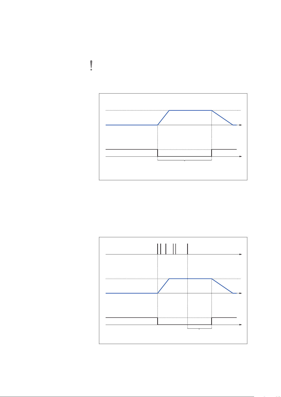
䊳
A
mbient temperature
T
arget temperature
Temporarily disabled (+064)
H
eater control system status
Orifice rim temperature
t
Starting time*
* Factory setting: 14:00:00 o'clock
On-time
t
Ambient temperature
Target temperature
Temporarily disabled (+064)
Heater control system status
Orifice rim temperature
Precipitation event
t
t
t
* Factory setting: 20 minutes
After-run time*
Mode #3 The heater is controlled based on the National Weather Service
(NWS) Standard. The heater control is active from a preset time
(starting time) on and continuously keeps the orifice rim temperature at the predetermined setpoint. The On-time may be adjusted
as well (1 … 1440 minutes).
Outside this On-time, the heater self-test is performed based on a
selectable interval (1 h … 7 d).
Fig. 5: Diagram of orifice
rim heater Mode #3.
Please note: This mode requires the OTT Pluvio2S system time to be set cor-
rectly. In case a power failure lasts longer than 10 minutes, the OTT Pluvio
ystem time will be lost. This will result in incorrect heater control system opera-
s
2
S
tion!
䊳
Mode #4 Heater control system is operated based on precipitation events.
Once precipitation has started, the heater control will be active
for a preset after-run time (1 ... 1440 minutes) and continuously
keep the orifice rim temperature at the predetermined setpoint.
Outside this after-run time, the heater self-test is performed based
on a selectable interval (1 h … 7 d).
Fig. 6: Diagram of orifice
14
rim heater Mode #4.
Page 15

4 Basic safety information
䊳
Please read these Operating Instructions before using the OTT Pluvio2S for the
first time! Make yourself completely familiar with the installation and operation
of the OTT Pluvio
䊳
The OTT Pluvio2S is used for automatic determination of the meteorological
precipitation intensity and amount of precipitation. Use the OTT Pluvio
as described in these Operating Instructions!
For further information ➝ see Chapter 3, „Introduction“.
䊳
Note all the detailed safety information given within the individual steps. All
safety information in these Operating Instructions is identified by the warning
symbol shown here.
䊳
Avoid heavy shaking and shocks during transport and operation!
he OTT Pluvio
T
mechanism. Only use the original packaging for transport!
䊳
Ensure the electrical, mechanical, and climatic specifications listed in the
technical data are adhered to.
For further information ➝ see Chapter 10, „Technical Data”.
䊳
Carry out all recommended maintenance work at the frequencies specified.
See Chapter 7, „Carrying out maintenance work“.
䊳
Do not make any changes or retrofits to the OTT Pluvio2S! If changes or
modifications are made, any warranty will be void.
䊳
Have a defective OTT Pluvio2S checked and repaired only by the OTT repair
center. On no account carry out repairs yourself! Only a qualified repair
followed by a factory final test ensures the specified measurement accuracy.
For further information ➝ refer to Chapter 8, „Repair“.
䊳
Properly dispose of the OTT Pluvio2S after taking out of service. On no account
put the OTT Pluvio
For further information ➝ see Chapter 9, „Notes on the disposal of used units“.
2
S! Keep these Operating Instructions for later reference.
2
is equipped with a highly sensitive electronic weighing
S
2
S into the normal household waste.
2
S only
15
Page 16

5 Installing the OTT Pluvio2S
The installation of the OTT Pluvio2S is carried out on a 2" pedestal made of galvanized steel (possible external diameter of pedestal 50 to 60.3 mm). The pedestal
must be securely attached to a concrete foundation having the appropriate dimensions. The pedestals that are available from OTT as accessories are fitted with a
bottom plate designed for this purpose.
The standard installation height recommended by the World Meteorological
Organization, WMO, for precipitation gauges is 1 meter (height of bucket
orifice). Alternatively, an installation height of 1.2 or 1.5 m is allowed.
Carefully choose your setup location according to your meteorological requirements. At the same time, ensure the location is free of vibration. For example,
traffic on a nearby road can affect the measurement results through vibration.
he maximum distance to the data collection device and the power supply to
T
which the OTT Pluvio
䊳
SDI-12 interface: 70 meters
䊳
RS-485 interface: 1000 meters
䊳
Pulse output: 1000 meters
For an OTT Pluvio
adapter of the orifice rim heater is 125 meters.
2
S is to be connected depends on the interface used:
2
S with orifice rim heater, the maximum distance to the mains
Please note: The OTT Pluvio
2
S precipitation gauge is equipped with a highly
sensitive electronic weighing mechanism! Install the unit only as described in these
2
Operating Instructions. To avoid damage to the OTT Pluvio
S weighing mechanism during installation: Avoid heavy shocks and large forces acting on the load
cell and the bracket for the bucket support (for these items, please refer to Fig. 8)!
5.1 Recommended cable types/maximum cable lengths
For operating the OTT Pluvio
䊳
power supply for the precipitation gauge,
䊳
power supply of the orifice rim heater (optional),
䊳
data collection device (SDI-12/RS-485 interface, pulse output),
䊳
ground terminal.
2
S, the following connections have to be made:
For the precipitation gauge power supply and the connection of the data collection device, a common connection cable can be used.
For an OTT Pluvio
2
S with orifice rim heater, an additional connection cable may
be used (alternatively two additional wires in the common connection cable).
Benefit: The orifice rim heater can be switched on and off separately from the precipitation gauge. In addition, power consumption of the orifice rim heater requires
a larger wire cross-section to be used for longer connection cables.
In total, the connection area of the OTT Pluvio
2
S has two cable entrances (rubber
grommets).
2
Please note: The protection concept of the OTT Pluvio
S against overloads
is designed such that all overvoltages occurring are discharged via a ground
connection. For this, the proper and functional installation of a grounding cable is
absolutely necessary! This is connected to the OTT Pluvio
2
S at the ground terminal
and at the other end in the area of the data collection device or directly at the
OTT Pluvio
2
S to a concrete footing ground or ground rod.
16
Page 17

Please note: All connection cables must be UV-resistant and suitable to be laid
in the ground!
Connection cable for data collection device/precipitation gauge
DI-12 interface – Cable length: maximum 70 m
S
1)
– Cable type: shielded low-voltage cable
– Wire size: 3 x 0.5 mm
S-485 interface – Cable length: maximum 1000 m
R
– Cable type: twisted-pair cable
2 2)
3)
;
shielded design
– Wire size: 2 x 2 x 0.5 mm
2
Pulse output – Cable length: maximum 1000 m
– Cable type: shielded low-voltage cable
– Wire size: 6 x 0.5 mm
2
The connection cable recommended in each case includes the wires for power
supply and data collection device.
)
1
with a point-to-point connection (no SDI-12 bus operation), a cable length of up to 300 m is possible.
2)
with standard SDI-12 wiring, alternative 4 x 0.5 mm2wire with separate power supply.
3)
he wires intended for power supply can be twisted pair, but do not have to be.
t
Connection cable for orifice rim heater power supply
4)
– Cable length: maximum 125 m
– Cable type: unshielded low-voltage cable
– Wire size: 1… 25 m: 2 x 0,5 mm
25 … 50 m: 2 x 1,0 mm
50 … 75 m: 2 x 1,5 mm
75 …125 m: 2 x 2,5 mm
2
2
2
2
Calculation is based on: output voltage of the 24 VDCpower supply (e.g. mains
adapter)
4)
optional: As necessary, alternatively provide two additional wires in the cable between data recording
unit and power supply considering adequate wire cross-section.
Grounding cable
– Cable length: max. 5 m
– Cable type: unshielded low-voltage cable
– Wire size: 1 x 10 mm
2
USB cable
If any changes are to be made to the factory settings, a USB cable is temporarily
required during commissioning (supplied). Maximum cable length: 3 m.
Please note: The USB port has no overload protection. It is designed to be
temporarily used as a service interface.
5.2 Required tools and equipment
䊳
Open-ended wrench, size 13 mm (supplied)
䊳
Phillips screwdriver, size: PH 2
䊳
Slotted screwdriver, size: 0.8 mm x 4 mm and 1.0 mm x 6 mm
䊳
Tool for stripping insulation on electrical cables
䊳
Wire-cutting pliers
䊳
For a connection cable with wires made of strands: Ferrules and
crimping pliers
17
Page 18
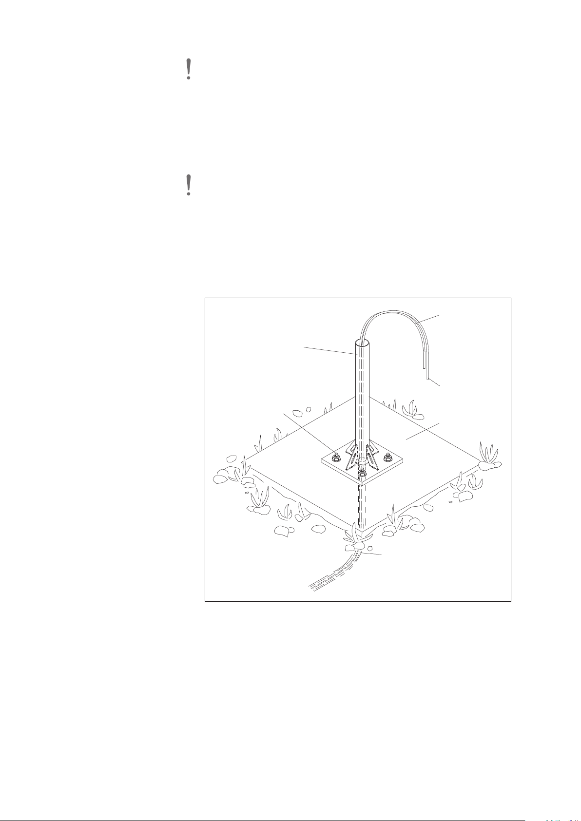
5.3 Preparing the installation location
Connection cable
to data collection
device/power
supply
Pedestal with
bottom plate
Mounting kit
for 2" pedestal
(4 x)
Empty pipe
Grounding cable
Concrete
foundation
Please note: The depth of the concrete foundation should be determined by the
local conditions: The foundation must reach into the frost-free zone in the ground.
The dimensions given for the foundation depth are typical values for conditions in
entral Europe.
C
We recommend that an empty conduit pipe (with a wire for pulling in) for the
onnection and grounding cables is incorporated into the concrete foundation.
c
䡵 Attach the pedestal with bottom plate to a concrete foundation measuring
approx. 45 x 45 x 80 cm using the “Mounting kit for 2" pedestal“ (refer to
ccessories); refer to Fig. 7 and appendix B.
a
Please note: The pedestal must be as vertical as possible!
䡵 Pull the connection cable for the data collection device/power supply into the
empty conduit pipe.
䡵 OTT Pluvio2S with orifice rim heater: As applicable, pull additional connection
cable for the orifice rim heater power supply into the empty conduit pipe.
䡵 In case the ground for the OTT Pluvio2S is implemented centrally in the area
of the data collection device: Also pull the grounding cable into the empty conduit pipe (alternatively, the ground is established directly at the OTT Pluvio
2
S
using a concrete footing ground or ground rod).
Fig. 7: The location prepared for
installing the OTT Pluvio
2
For an OTT Pluvio
rim heater, an additional connection
cable may be used for supplying
power to the orifice rim heater.
The cables may alternatively be routed
outside of the pedestal. To protect the
cables (e.g. against animal bites), routing
the cables inside the pedestal is recom-
S with orifice
2
S.
18
Page 19
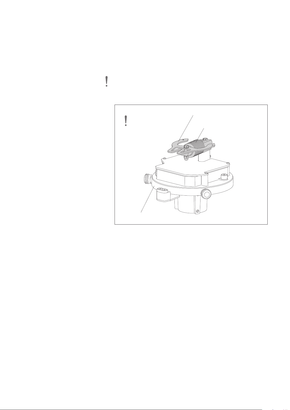
5.4 Preparing the base plate
Base plate
Bracket bucket support
Load cell
Highly sensitive
electronic weighing
mechanism – handle
with care!
䡵 Carefully transport the OTT Pluvio2S to the installation location in the closed
shipping carton
䡵 Open the shipping carton and remove the acceptance certificate (FAT), the
olybag including installation accessories and possibly further existing
p
accessories.
䡵 Remove the pipe housing with collecting bucket and put it first aside.
䡵 Remove and open the inner carton (consider the hints on the carton) and
emove the shaped foam part
r
䡵 Remove the base plate from the inner carton and carefully place it on a flat
urface. Please note: Do not use the load cell or bracket for the bucket
s
support to lift the base plate!
Fig. 8: OTT Pluvio2S base plate.
19
Page 20
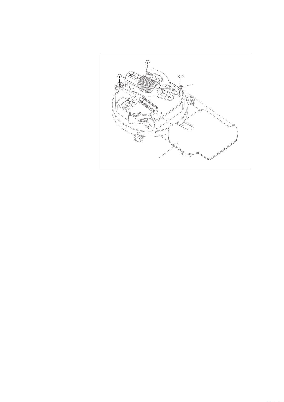
䡵 Unscrew 4 Phillips screws on the cover of the electronics unit approx. 3 mm,
Phillips screw
(4 x)
Electronic
unit cover
Foam rubber seal
raise the cover slightly and pull it off forwards. When the foam rubber seal
or the cover is stuck to the surface below, carefully pry the cover off using a
f
slotted head screwdriver.
Fig. 9: Removing the cover
from the electronics unit.
5.5 Preparing the connection cable
Connection cable for data collection device/power supply:
䡵 Cut the connection cable so that it sticks out approx. 30 – 35 cm above the
pedestal. (The „excess“ cable can be stored in the pedestal later.)
䡵 Take the rubber grommet out of the electronics unit (see Fig. 13). Remove the
white blanking plug from the rubber grommet and push the grommet onto the
connection cable.
䡵 Strip off approx. 10 cm of the outer sheath of the connection cable.
䡵 Strip off approx. 5 mm of the insulation of the individual wires.
䡵 Put the cable shielding together and twist it.
䡵 For a stranded connection cable: push ferrules onto the wires and crimp using
crimping pliers.
䡵 Connect the cable to the supplied screw terminal strips (included in the poly-
bag); see Fig. 10 and 11:
– SDI-12 interface ➝ 8-wire screw terminal strip, contact 3
– RS-485 interface
2-wire ➝ 8-wire screw terminal strip, contacts 1/2
4-wire ➝ 6-wire screw terminal strip, contacts 5/6 +
8-wire screw terminal strip, contacts 1/2
– Pulse output ➝ 6-wire screw terminal strip, contacts 1/2
(Accu RT-NRT) + contacts 3/4
(pulse status information; as required)
– Power supply ➝ 8-wire screw terminal strip, contacts 6/7
(precipitation gauge) + contacts 5/8
(orifice rim heater; optional)
Orifice rim heater connection cable (optional)
20
䡵 If using a separate connection cable for the orifice rim heater: Assemble the
cable as described above and connect to the 8-wire screw terminal strip, see
Fig. 11.
Page 21
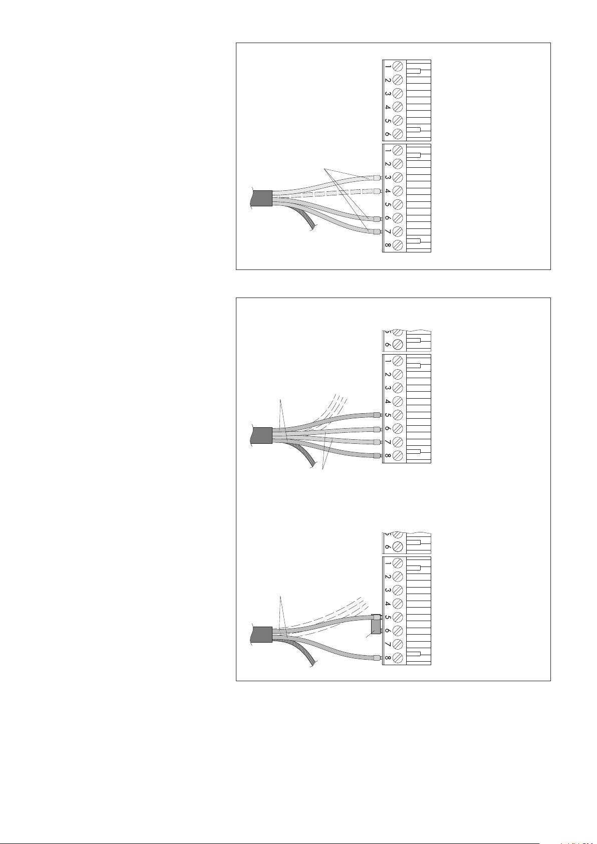
+12 … +24 V
DC
Pulse Out mm/inch A
Pulse Out mm/inch B
Pulse Out Status A
Pulse Out Status B
Data RS-485 TX - B
Data RS-485 TX - A
GND
Heating GND
Data GND
Heating +24 V
D
C
SDI-12 Data
Data RS-485 RX - A / R S - 4 8 5 - A
Data RS-485 RX - B / R S - 4 8 5 - B
SDI-12 default
wiring
Fig. 10: Connecting the cable for the
Power supply for
heater; 24 V
DC
precipitation gauge; 12 … 24 V
D
C
Jumper
Method B: common power supply for heater and precipitation gauge
Method A: separate supply for heater and precipitation gauge
+12 … +24 V
DC
GND
Heater GND
Data GND
Heating +24 V
D
C
SDI-12 Data
Data RS-485 RX - A / R S - 4 8 5 - A
Data RS-485 RX - B / R S - 4 8 5 - B
+12 … +24 V
DC
GND
Heater GND
Data GND
Heating +24 V
DC
SDI-12 Data
Data RS-485 RX - A / R S - 4 8 5 - A
Data RS-485 RX - B / R S - 4 8 5 - B
Data RS-485 TX - A
Data RS-485 TX - A
data recording device/power supply for
the precipitation gauge to 6-wire and/or
8-wire screw terminal strip (example
SDI-12 interface).
Standard SDI-12 wiring has three wires
(SDI-12 DATA, GND, and power supply
(+12 V)). For separate power supplies, an
additional GND wire is available.
Contacts 4, 6, and 8 of the 8-wire screw
terminal strip are jumpered internally!
Fig. 11: OTT Pluvio2S with orifice
rim heater: Connecting options for
power supply of the precipitation gauge
and orifice rim heater.
Please note: For version B, common
supply voltage must be 24 V
(Otherwise, heating power is reduced;
!
DC
refer to "Specifications".)
As necessary, two separate cables may
be used (e.g. separate cable for optional
orifice rim heater).
For clarity, the wires for connecting the data
recording unit are shown as dashed lines.
The jumper is included (polybag
containing installation accessories).
Contacts 4, 7, and 8 of the 8-wire screw
terminal strip are jumpered internally.
21
Page 22
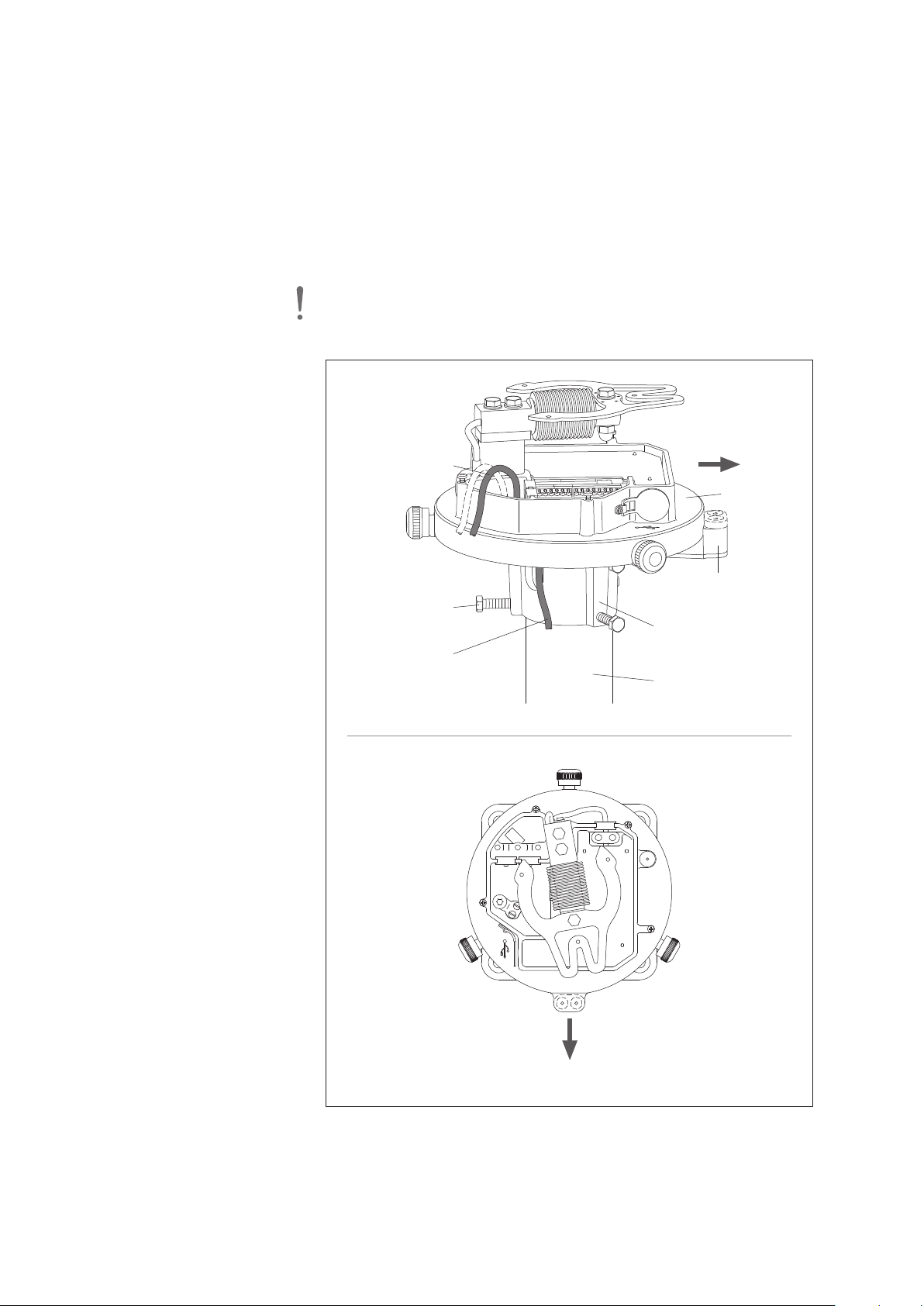
5.6 Installing the base plate on the pedestal
Base plate
Base plate flange
Pedestal
Hexagon bolts
(6 x)
Grounding cable
Connecting cable
South*
Orifice rim heater
connector block
* on the southern
hemisphere: north
South*
䡵 Place the base plate onto the pedestal such that the connection and grounding
cables come out of the slit in the base plate flange (see Fig. 14).
䡵 Lead connection and grounding cables through the opening in the base plate
pwards.
u
䡵 Rotate the base plate so that terminal block of the orifice ring
heater is facing southwards*! In extreme climatic conditions, this will
prevent incorrect precipitation value output. These may occur during heavy
apid temperature variations together with lateral solar irradiation.
r
* on the southern hemisphere: northwards
䡵 Insert the six hexagon bolts into the base plate flange with open-ended wrench,
size 13 mm (supplied).
Please note: insert all hexagon bolts approximately to the same depth! Do
not yet fully tighten the hexagon bolts!
Fig. 12: Installing base plate onto pedestal.
22
Page 23
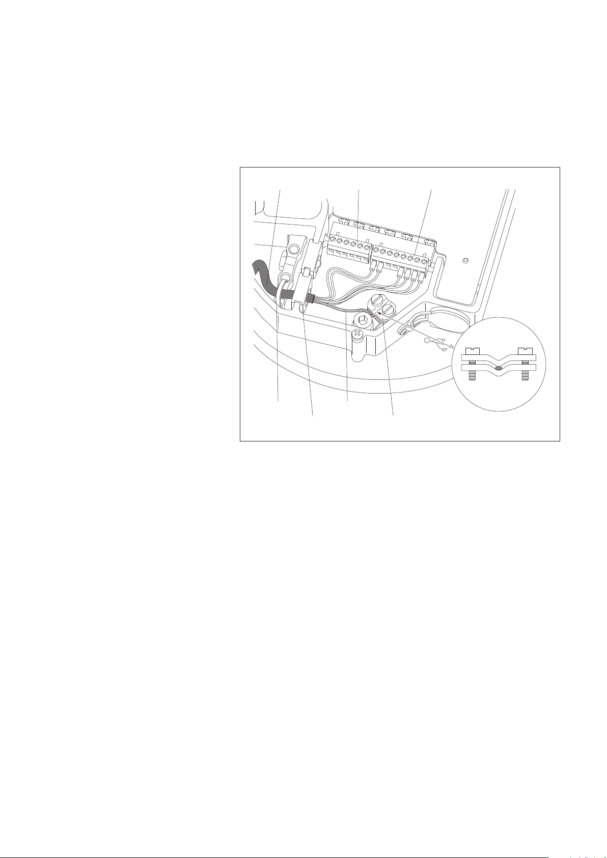
5.7 Connecting the connection cable
Connecting cable
Shield terminal
ShieldCable tie
Rubber grommet
8-wire screw terminal6-wire
䡵 Push rubber grommet with connection cable into the slot.
䡵 Connect 6-wire and 8-wire screw terminal strip to the appropriate PCB sockets.
䡵 Connect the twisted shielding of the cables to the terminal, refer to Fig. 13.
If necessary, pull back connection cable and store in pedestal (raise base plate
䡵
again if necessary).
䡵 Push a cable tie through the holes in the base plate and fix the connection
cable using the cable tie.
Fig. 13: Connecting the cable
in the electronics unit.
(The Figure shows the example of a
standard RS-485 wiring (2-wire) with
optional orifice rim heater. The orifice
rim heater is supplied separately.)
5.8 Connecting the grounding cable
䡵 Cut the grounding cable (cross-section 10 mm2) to approx. 25 ... 30 cm.
䡵 Strip off approx. 10 mm of the grounding cable insulation and connect to the
earth terminal on the base plate underside. For a stranded grounding cable:
push on ferrules and crimp using crimping pliers.
䡵 If necessary, pull back the grounding cable and store in pedestal (lift the base
plate once more if necessary).
䡵 Connect the other end of the grounding cable to a foundation or earthing rod.
23
Page 24
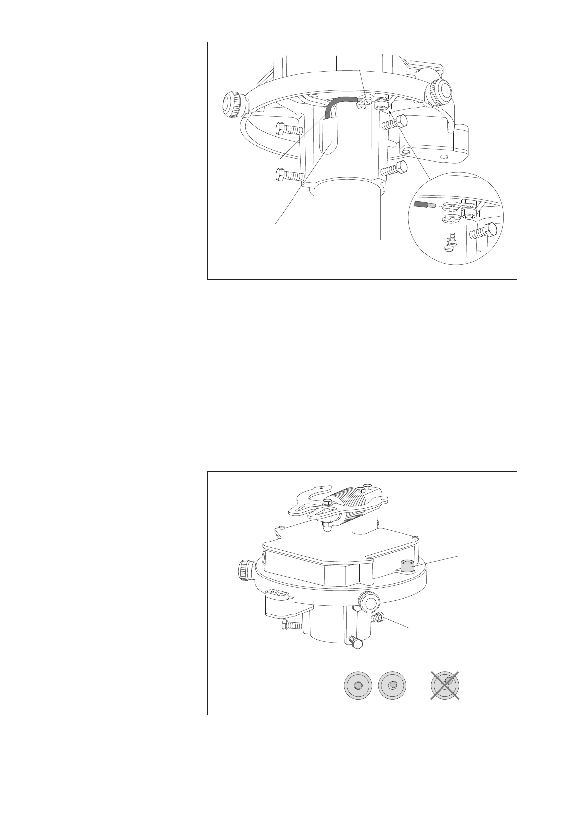
Grounding cable
Base plate
flange slot
Ground
terminal
Fig. 14: Connecting the grounding cable.
Bubble level
indicator
Hexagon bolt
(6 x)
OK
5.9 Aligning the base plate
䡵 First, fix the base plate using the three upper hexagon bolts. Alternately tighten
the bolts until they are all contacting the pedestal. Important: Insert all hexagon
bolts approximately to the same depth!
䡵 Using the lower hexagon bolts, adjust the base plate so that the air bubble is
within the indicator marked ring. Inserting a hexagon bolt will cause the air
bubble to move towards this bolt position. In case of large adjustment travel
(pedestal is outside the vertical position for several degrees), turn the opposite
hexagon bolts counter-clockwise as necessary!
䡵 Alternately tighten all hexagon bolts while avoiding any distortion of the base
plate! Maximum torque: 6 Nm.
䡵 Again check bubble level for correct adjustment.
Fig. 15: Levelling the OTT Pluvio2S unit.
Correct operation of the weighing
mechanism is insured only if the base
plate is correctly levelled in horizontal
direction!
24
Page 25
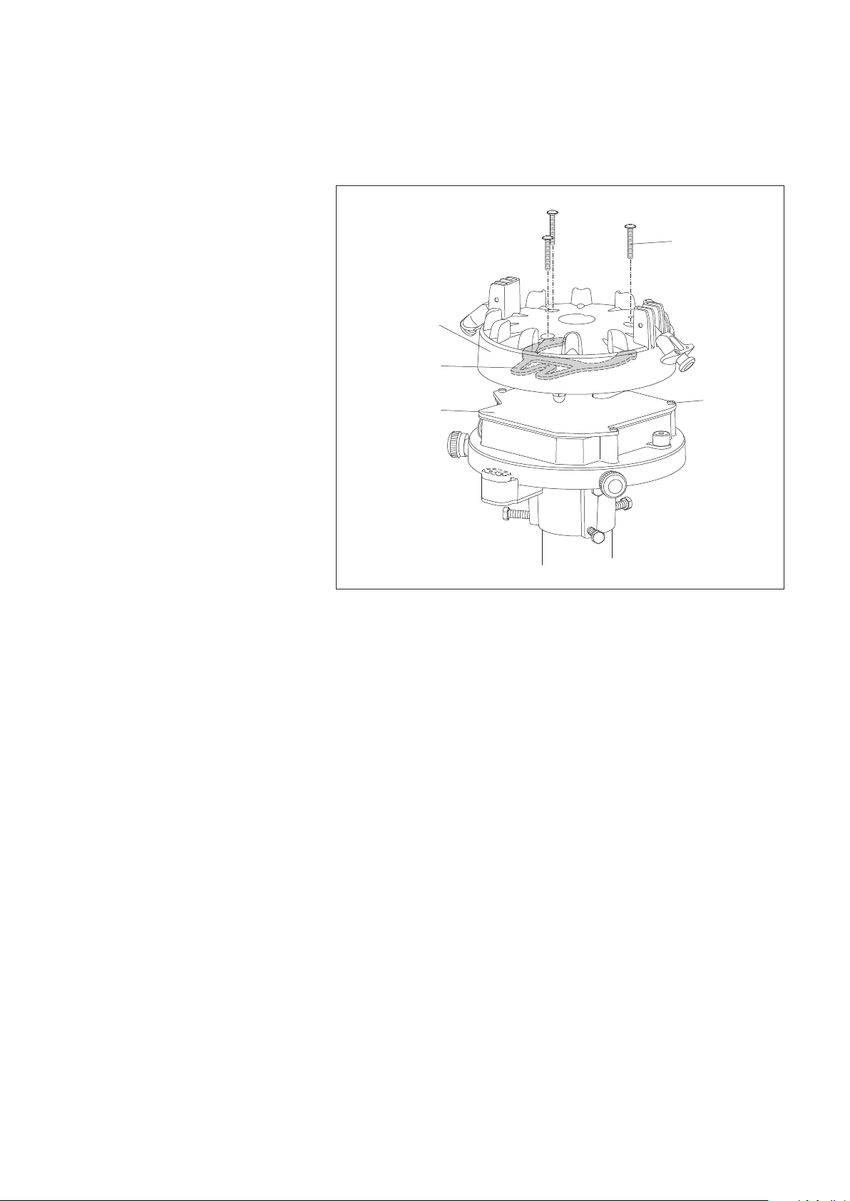
5.10 Performing final work
Bracket bucket
support
Phillips screw
(3 x)
Bucket support
Phillips screw
(4 x)
Electronic unit
cover
䡵 Replace the electronics unit cover and tighten the four Phillips screws.
䡵 Align the bucket support (refer to decal) and carefully place it onto the bracket
for the bucket support.
Secure the bucket support using three Phillips screws (included in polybag).
䡵
Fig. 16: Placing and securing
the bucket support.
䡵 Take the collecting bucket out of the pipe housing and remove all shaped foam
parts.
䡵 Align the collecting bucket and place it onto the bucket support taking into
account the anti-rotation protection, refer to Fig. 17!
䡵 Use the two spring-loaded terminals to secure the collecting bucket.
25
Page 26
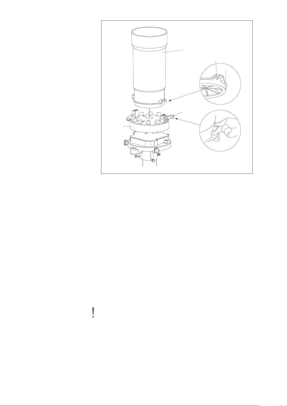
B
ucket
support
Anti-rotation protection
Collecting bucket
S
pring-loaded
t
erminal
Fig. 17: Placing the collecting
bucket onto bucket support.
䡵 As necessary: change the factory settings using the OTT Pluvio2operating
software. For installation procedure and using the operating software, refer to
Chapter 7.6.
Factory settings:
– SDI-12 sensor address 0
– serial interface SDI-12
– temperature unit of measurement °C
– intensity unit of measurement mm/h
– pulse factor 0.1
– pulse output rate 5 Hz
– orifice rim heater* on
– heating mode* 1, continuously on
– orifice rim heater target temperature* +4 °C
* version with ring heater option
䡵 For temperatures below 0 °C, add antifreeze; for details, refer to Chapter 7.2.
䡵 Connect the free cable end of the connecting cable to the data collection device
and the power supply.
䡵 When using a separate connecting cable for the optional orifice rim heater:
Connect the cable for the orifice rim heater to the power supply.
䡵 Configure the data collection device. For this, refer to the manual for the data
collection device. SDI-12 commands and responses used: refer to Chapter 6.
Please note: Connect the shield of the connection cables also at the data
collection device/power supply!
26
Page 27
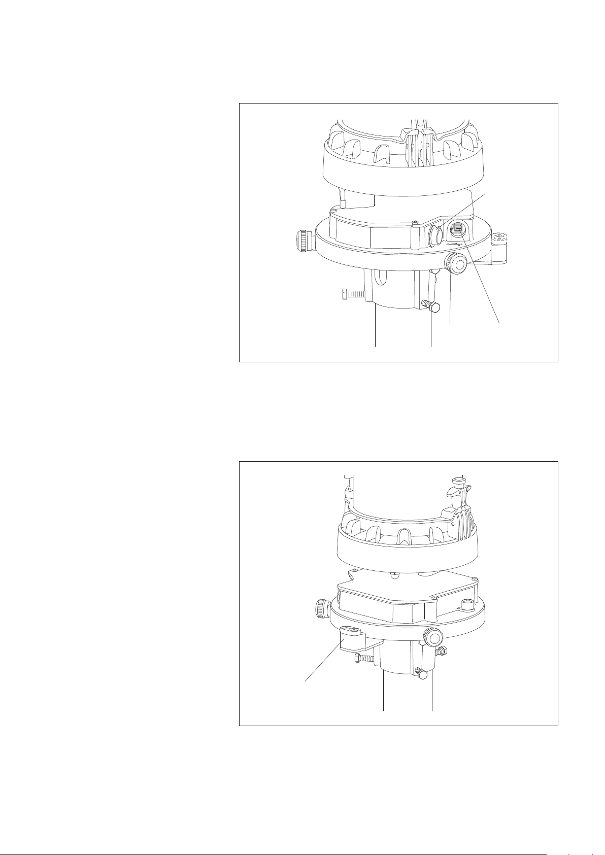
䡵 Carry out functional check: Remove cover of the USB interface ➝ red LED must
Cover
Red LED
USB interface
Connector block including
sockets for the plug contacts
for the orifice rim heater
briefly flash once a second.
Replace cover.
䡵
Fig. 18: Carrying out the functional check.
䡵 Align the pipe housing and place it onto the base plate. The pipe housing must
completely seat on the base plate (refer to the detail drawing in Fig. 20)!
2
OTT Pluvio
S with orifice rim heater: Ensure that the sockets in the connection
block are not contaminated.
Abb. 19: Connection block for the plug
contacts for the orifice rim heater.
27
Page 28
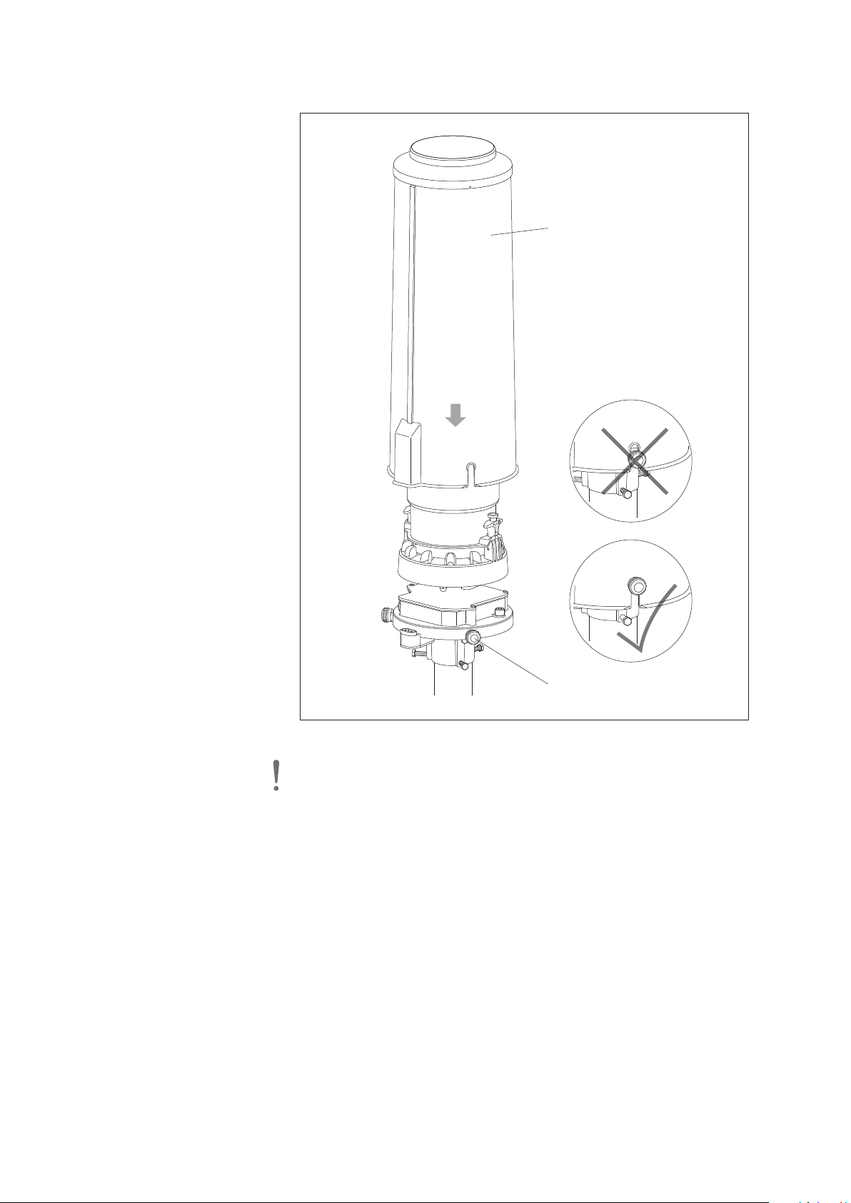
䡵 Tighten three knurled bolts.
Pipe housing
Knurled bolt
(3 x)
Fig. 20: Fitting the pipe housing and
tightening the knurled screws.
Please note: Always place and remove
the pipe housing of the OTT Pluvio2S with
orifice rim heater straightly!
Please note: After startup, the OTT Pluvio
measured values. During this period, the precipitation values are identified in the
status information as not completely available yet.
2
S uses a 2 minute delay to output the
28
Page 29

6 SDI-12 commands and responses
.1 Basic commands
6
All SDI-12 basic commands are implemented in the OTT Pluvio
operation of the OTT Pluvio
2
S.
Conventions applicable to measured value formats:
p – Sign (+,–)
b – Number ahead of the decimal point (Output without leading zeros)
e – Number after the decimal point
Command Response Description
2
S. The following SDI-12 basic commands are relevant for the
a! a<CR><LF>
aI! allccccccccmmmmmm …
… vvvxxxx<CR><LF>
aAb! b<CR><LF>
?! a<CR><LF>
aM! / aM1!
atttn<CR><LF>
Acknowledgment active
a – sensor address; factory setting = 0
Send identification
a – sensor address
l – SDI-12 protocol version
l
cccccccc – manufacturer identification (company name)
mmmmmm – sensor identification
vvv – sensor version (firmware)
xxxxxx – serial number
2
OTT Pluvio
S response = 013OTT HACHPLUV2S100xxxxxx
Change sensor address
a – old sensor address
b – new sensor address
Query sensor address
(not possible at SDI-12 bus operation)
a – sensor address
Start measurement
a – sensor address
ttt – time in seconds until the sensor
has determined the measurement result
OTT Pluvio
2
S response = 000
n – number of measured values
OTT Pluvio
2
S response = 9 to aM
3 to aM1!
aMC! / aMC1!
atttn<CR><LF>
Start measurement and request CRC (Cyclic Redundancy
Check). For details, see command aM!. The responses to
the D0! … aD2! commands in this case are extended by
a CRC value (example):
a<value1><value2><value3><CRC><CR><LF>
aC! / aC1!
atttnn<CR><LF>
Start concurrent measurement (simultaneous measurement
with multiple sensors on one bus line). For details see command aM!. The number of measured values in the response
to this command is two-digit: nn = 09 or 03.
aCC! / aCC1!
atttnn<CR><LF>
Start concurrent measurement (simultaneous measurement
with multiple sensors on one bus line) and request CRC
(Cyclic Redundancy Check). For more details, see command
aM!. The number of measured values in the response to
these commands is two-digit: nn = 09 or 03.
The responses to the D0! … aD2! commands in this case
are extended by a CRC value (example):
a<value1><value2><value3><CRC><CR><LF>
Note: Each aM! command resets the total measured values Accu RT-NRT and Accu NRT to zero!
29
Page 30

Command Response Description
aD0!*
* after
M!, aMC!,
a
C!, aCC!
a
aD1!*
after
*
M!, aMC!,
a
aC!, aCC!
aD2!*
* after
M!, aMC!,
a
aC!, aCC!
a<value1><value2><value3> …
… <CR><LF>
a<value4><value5><value6> …
… <CR><LF>
a<value7><value8><value9> …
… <CR><LF>
Send data
a – sensor address
<value1> – Intensity RT
mm/h]: pbbbb.eee (0.000 … 3000.000)
[
[mm/min]: pbb.eee (0.000 … 50.000)
[inch/h]: pbbb.eee (0.000 … 118.110)
[inch/min]: pb.eee (0.000 … 1.969)
value2> – Accu RT-NRT
<
[mm]: pbbb.eee (0.000 … 500.000)
[inch]: pbb.eee (0.000 … 19.685)
<value3> – Accu NRT
Format as Accu RT-NRT
Send data
a – sensor address
value
4> – Accu total NRT
<
Format as Accu RT-NRT
<
alue5> – Bucket RT
v
[mm]: pbbb.eee (7.000 … 400.000)
[inch]: pbb.eee (0.276 … 15.748)
value
6> – Bucket NRT
<
Format as Bucket RT
Send data
a – sensor address
value
7> – Temperature of load cell
<
[°C]: pbb.e (–40.0 … +85.0)
[°F]: pbbb.e (–40.0 … +185.0)
<
value
8> –Heater status
pbbb
+0 = Orifice rim heater working properly
+1 = W: Temp. of orifice ring rim > 40 °C
+2 = A: Temp. of orifice ring rim < –20 °C
+4 = A: Temperature sensor not connected
+8 = A: Temperature sensor short-circuited
+16 = A: Communication to rim heater
module is defective (the pipe hous-
ing may have been removed)
+32 = A: Orifice rim heater self-test failed
+64 = W: Orifice rim heater temporarily
disabled
+128 = W: Orifice rim heater disabled or not
present
W = warning; A = alarm.
When the OTT Pluvio
2
S unit outputs other values than those
indicated here, several events have occurred simultaneously.
In such a case, the individual values are added up.
Example: “+65” ➝ Sum obtained from warnings “+1” and
“+64”. The status information output – assuming the cause
has been rectified – will be reset the next time the command
aM! is used.
Note on Bucket RT and Bucket NRT values: These level values are not exactly zeroed in case of an empty
collecting bucket. Depending on the climatic ambient conditions, they vary by maximum ±10 mm around zero.
30
Page 31

Command Response Description
(continuation
of aD2!)
aD0!*
* after
aM1!, aMC1!,
C1!, aCC1!
a
a<value1><value2><value3> …
… <CR><LF>
<value9>
– Status
pbbbb
+0 = Precipitation gauge working
roperly
p
+1 = W: Bucket level ≥ 80 %
+2 = W: USB interface is/was connected
+4 = W: Restart (due to power failure)
+8 = W: Restart (due to firmware)
+16 = W: Weight change out of range
+32 = W: Supply voltage < 7 V
+64 = A: Weight measurement unstable
+128 = A: Weight measurement incorrect
+256 = A: Weight below minimum
+512 = A: Weight above maximum
+1024 = A: No weight calibration
W = warning; A = alarm.
When the OTT Pluvio
2
S unit outputs other values than those
indicated here, several events have occurred simultaneously.
In such a case, the individual values are added up.
Example: “+34” ➝ Sum obtained from warnings “+2” and
“+32”. The status information output – assuming the cause
has been rectified – will be reset the next time the command
aM! is used.
Send data
a – sensor address
<value1>
– Temperature of electronics unit
(approximate ambient temperature incl. delay)
[°C]: pbb.e (–40.0 … +85.0)
[°F]: pbbb.e (–40.0 … +185.0)
<value2>
– Supply voltage
[V]: pbb.e (+4,5 … +28.0)
<value3>
– Temperature of orifice ring rim
[°C]: pbb.e (–40.0 … +85.0)
[°F]: pbbb.e (–40.0 … +185.0)
More information on the SDI-12 basic commands can be found in the document SDI-12; A Serial-Digital Interface
Standard for Microprocessor-Based Sensors, Version 1.3 (see Internet page www.sdi-12.org).
31
Page 32

6.2 Advanced SDI-12 commands
All advanced SDI-12 commands start with an “
al information from an OTT Pluvio
ommand Response Description
C
䊳
Read out firmware version
2
S through the transparent mode of a datalogger or to configure an OTT Pluvio2S.
aOOV! acc.cc.c<CR><LF> Read out firmware version of the OTT Pluvio
O“ for OTT. These commands may be used, for example, to retrieve addition-
2
S
a – sensor address
cc.cc.c – firmware version
Example: V1.00.00 (first firmware version supplied)
䊳
Set/read the unit for the temperature measured values
aOUTb! ab<CR><LF> Set unit
aOUT! ab<CR><LF> Read out unit
a – sensor address
b – 0 = °C; factory setting
1 = °F
䊳
Set/read unit for the intensity measurements
aOUIb! ab<CR><LF> Set unit
aOUI! ab<CR><LF> Read out unit
a – sensor address
b – 0 = mm/min
1 = mm/h; factory setting
2 = inch/min
3 = inch/h
Note: This command changes the units for “Accu …“ and “Bucket …” at the same time; mm ↔ inch
䊳
Set/read pulse output rate
aOCIb! ab<CR><LF> Set pulse output rate
aOCI! ab<CR><LF> Read pulse output rate
a – sensor address
b – 0 = 5 Hz; factory setting
1 = 2 Hz
䊳
Set/read pulse factor
aOSIb! ab<CR><LF> Set pulse factor
aOSI! ab<CR><LF> Read pulse factor
a – sensor address
b – 0 = 0.05 mm
1 = 0.1 mm; factory setting
2 = 0.2 mm
3 = 0.5 mm
4 = 1.0 mm
32
Page 33

䊳
Set/read orifice rim heater mode (OTT Pluvio2S with orifice rim heater)
aOCHb! ab<CR><LF> Set mode
aOCH! ab<CR><LF> Read mode
a – sensor address
b – 0 = Orifice rim heater disabled
1 = Mode #1; continuously ON
= Mode #2; temperature range control
2
3 = Modus 3; NWS Standard
4 = Modus 4; precipitation events
䊳
Set/read orifice rim heater target temperature (OTT Pluvio2S with orifice rim heater)
aOCHSpb! apb<CR><LF> Set target temperature
aOCHS! apb<CR><LF> Read target temperature
a – sensor address
p – sign (+)
b – 2 … 9 (+2 … +9 °C);
factory setting +4 °C
䊳
Set/read orifice rim heater lower temperature limit (OTT Pluvio2S with orifice rim heater)
Orifice rim heater mode: #2
aOCHGpbb! apbb<CR><LF> Set lower temperature limit
aOCHG! apbb<CR><LF> Read lower temperature limit
a – sensor address
p – sign (+,–)
bb – 40 … 9 (–40 … +9 °C);
factory setting –30 °C
䊳
Set/read orifice rim heater on-time/after-run time (OTT Pluvio2S with orifice rim heater)
Orifice rim heater mode: #3, #4
aOCHDbbbb! abbbb<CR><LF> Set on-time/after-run time
aOCHD! abbbb<CR><LF> Read on-time/after-run time
a – sensor address
bbbb – 1 … 1440 (1 … 1440 minutes);
factory setting 20 minutes
䊳
Set/read orifice rim heater starting time (OTT Pluvio2S with orifice rim heater)
Orifice rim heater mode: #3
aOCHZhh:mm:ss! ahh:mm:ss<CR><LF> Set starting time
aOCHZ! ahh:mm:ss<CR><LF> Read starting time
a – sensor address
hh:mm:ss – 00:00:00 … 23:59:59;
factory setting 14:00:00 Uhr
䊳
Set/read orifice rim heater self-test interval (OTT Pluvio2S with orifice rim heater)
Orifice rim heater mode: #1, #2, #3, #4
aOCHTbbbb! abbbb<CR><LF> Set self-test interval
aOCHT! abbbb<CR><LF> Read self-test interval
a – sensor address
bbbb – 1 … 10 080 (1 … 10 080 minutes);
factory setting 60 minutes*
* by OTT Pluvio2operating software adjustable values: 1, 12, 24 hours; 2, 3, 4, 5, 6, 7 days
33
Page 34

䊳
Set/read serial interface (SDI-12 or RS-485)
aOCLb! ab<CR><LF> Set serial interface
aOCL! ab<CR><LF> Read serial interface
a– sensor address
b – 0 = SDI-12; factory setting
1 = RS-485 2-wire
= RS-485 4-wire
2
䊳
Set/read protocol on RS-485 interface
aOCMb! ab<CR><LF> Set protocol
aOCM! ab<CR><LF> Read protocol
a – sensor address
b – 0 = SDI-12 protocol; factory setting
1 = ASCII (RS-485 command line mode)
䊳
Set/read data transmission rate (baudrate) at RS-485 interface using the ASCII-protocol
aOCRb! ab<CR><LF> Set data transmission rate
aOCR! ab<CR><LF> Read data transmission rate
a – sensor address
b – 0 = 1 200 bit/s
1 = 2 400 bit/s
2 = 4 800 bit/s
3 = 9 600 bit/s factory setting
4 = 19 200 bit/s
5 = 57 600 bit/s
6 = 115 200 bit/s
䊳
Reset Accu total NRT
aOMR! a<CR><LF> Reset Accu total NRT
a – sensor address
34
Page 35

6.3 RS-485 command line mode (ASCII text retrieval)
When using the RS-485 interface, the default transmission protocol is the SDI-12 protocol. This assumes that the data recording
device connected can process the SDI-12 protocol. The OTT netDL or OTT DuoSens dataloggers can handle this protocol.
2
To easily incorporate the OTT Pluvio
implemented in the OTT Pluvio
and various settings made. This command set must be implemented in the data recording device. In the OTT Pluvio
number of operating parameters are to be set using the OTT Pluvio
a
S unit into any measuring station infrastructure, a so-called command line mode is
2
S. Using an ASCII character format command set, any measured values can be retrieved
2
perating software.
o
2
S unit,
Switching to RS-485 command line mode
Communication interface: RS-485 or RS-485 4-wire
S-485 protocol type: ASCII Text …
R
Transmission parameters … 57 600; 19 200; 9 600; 4 800; 2 400; 1 200 bd (8 N 1)
Units
Temperature values: °C · °F
Intensity: mm/min · mm/h
inch/min · inch/h
Commands
M[separator]<CR> returns the measurements “Intensity RT”; “Accu RT/NRT;” “Accu NRT”;
“Accu total NRT”; “Bucket RT”; “Bucket NRT”; “Temperature load cell”;
“Heater status”, “Status”, as a sequence of ASCII characters.
After the character M, any separator can follow optionally. This character then separates the individual values from each other in the answer from the OTT Pluvio
2
Refer to Chapter 6.1. for a description of measured value formats and status information.
S.
E[separator]<CR> additionally to the command M returns the values “Temperature electronics unit”,
“Supply voltage” and “Temperature orifice ring rim”
MCRC[separator]<CR>
ECRC[separator]<CR>
request measured values optionally with CRC (Cyclic Redundancy Check)*. In this
case, the measured values output are extended by a CRC value.
RPT<CR> repeats the last command executed; e.g. when CRC-check* is erroneous. In this case
2
the OTT Pluvio
S does not determine new measured values, but displays the
buffered measured values repeatedly.
R<CR> resets the value “Accu total NRT” to zero
W<CR> switches the orifice rim heater ON
S<CR> switches the orifice rim heater OFF
I<CR> retrieves various pieces of information from the device: Serial number, firmware,
device version, unit, hardware index, PCB number, load cell number
Examples
M;<CR> +0.000;+0.000;+0.000;+0.000;+269.280;
+269.281;+24.5;+255;+0<CR><LF>
MCRC;<CR> +0.000;+0.000;+0.000;+0.000;+269.277;
+269.281;+24.5;+255;+0CRC9EFA;<CR><LF>
E;<CR> +0.000;+0.000;+0.000;+0.000;+269.280;+269.281;
+24.5;+255;+0;+25.4;+12.1;+99.9CRCC8C8;<CR><LF>
R<CR> OK<CR><LF>
W<CR> Heating ON<CR><LF>
S<CR> Heating OFF<CR><LF>
I<CR> 361534;V1.03.0;200;mm/h;H1;800380210;31353651;<CR><LF>6
Note: Each command M or E resets the total measured values Accu RT-NRT and Accu NRT to zero!
* cyclic redundancy check: method for determining a checksum in order to be able to detect errors during data transmission.
(Technical details: CRC-CCITT (CRC-16); CRC order: 16; CRC polynom: 1021; Initial value: 0; Final XOR value: 0
35
Page 36
7 Performing maintenance operations
To ensure smooth operation of the precipitation gauge, we recommend to perform
the following maintenance operations at the intervals given:
䊳
Emptying: bucket level ≥ 80 %
䊳
Add anti-freeze: ambient temperature < 0 °C
䊳
Visual inspection: once a year
䊳
Check measurement: once a year
7.1 Emptying the collecting bucket
You may empty the bucket contents at any time, irrespective of the level. Any collecting bucket overflow will result in incorrect measurements, but will not damage
he precipitation gauge.
t
– When to empty?
When the collecting bucket level is 80 % or more (=
refer to Bucket RT/Bucket NRT values; Status information includes warning “+1”;
response (value 9) to SDI-12 command “aD2!” after “aM!”, “aMC!”, “aC!”
oder “aCC!”.
– Interval
Typically once or twice a year;
(more frequently in regions with heavy amount of precipitation).
^
320 mm of precipitation);
CAUTION Risk of injury by falling collecting bucket!
A completely filled collecting bucket has a weight of approx. 8.5 kg!
䊳
Be careful when emptying the collecting bucket.
䊳 As applicable, ask another person to assist.
How to empty the collecting bucket:
䡵 Loosen three knurled screws.
䡵 Remove the pipe housing upwards.
䡵 Remove both spring-loaded terminals and carefully remove the collecting bucket.
Please note: Proceeding carelessly, e.g. roughly placing the filled collecting
bucket on the bucket support, may damage the weighing mechanism.
䡵 Empty the collecting bucket.
䡵 Place the collecting bucket on the bucket support (note the anti-rotation protec-
tion) and secure it using the two spring-loaded terminals, refer to Fig. 17.
䡵 Align the pipe housing and install it, refer to Fig. 20.
䡵 Tighten three knurled screws.
7.2 Adding anti-freeze agent for winter operation
For temperatures below 0 °C *, we recommend anti-freeze agent be added to the
collecting bucket. This anti-freeze causes the collected solid precipitation to
gradually thaw in the collecting bucket.
Moreover, it prevents the unit from getting damaged when the
collecting bucket is filled for more than 80 % and the content
is frozen. Please use the anti-freeze POWERCOOL DC 924-PXL in an aqueous
solution, refer to Appendix E (manufacturer: Thermochema GmbH, A-4460
Losenstein; Phone +43 7255 4244-0; www.thermochema.at.)
* temperatures all over the day of continuously < approx. –5 °C. When temperatures of above 0 °C
occur for a longer period during the day, adding anti-freeze is not necessary.
36
Page 37

How to add anti-freeze agent:
䡵 Preparing the anti-freeze solution: Mix 1 litre of anti-freeze with 0.4 litre of
ater.
w
䡵 Carefully add anti-freeze solution to the collecting bucket (the pipe housing
does not have to be removed for this).
Please note: Add anti-freeze agent only as an aqueous solution (add 40 % of
water)! Never use neat! (POWERCOOL is hygroscopic.)
Note on disposing of anti-freeze solution
Typically, the anti-freeze solution of a single precipitation gauge may be disposed
of into the public sewage system. However, observe all applicable local regulations.
Please refer to your local authority responsible for questions regarding disposal
and/or contact Thermochema GmbH.
Note on winter operation without anti-freeze
Basically, the unit may be operated in the winter season without adding antifreeze solution. However, this mandatorily requires the collecting bucket to be
checked and emptied in regular intervals!
Please note: When the accumulated precipitation freezes that has
filled the collecting bucket up to 80 %, this may result in permanent damage to the weighing mechanism.
Note on third-party anti-freeze solution products
Basically, third-party products may be used provided the following requirements
are met:
䊳
Good solubility in water, low-density (i.e. the anti-freeze agent does not settle
below the water).
䊳
Low evaporation (do not use methanol).
䊳
Little corrosive effect on aluminium and stainless steel.
䊳
Low freezing point even with high collecting bucket level.
䊳
Low hygroscopic properties (absorption of moisture from ambient air, which
would affect the measurement results).
䊳
Note chemical compatibility with collecting bucket (ASA).
䊳
No gumming after use in open containers for several months.
7.3 Performing the visual inspection
䡵 Check smooth movement of the collecting bucket in all directions at the lower
edge of the bucket orifice. The collecting bucket upper edge may not contact
the pipe housing!
䡵 If present, carefully remove any contamination (e.g. insects, insect nests, spider
webs, etc.), and icing.
7.4 Additional checks in cases of defect
䊳
Is the collecting bucket distorted?
䊳
Is the collecting bucket correctly positioned on the bucket support?
䊳
Is the pipe housing correctly positioned and not damaged?
䊳
Is the weighing mechanism contacting other components, e.g. caused by
contamination?
䊳
Is the red LED flashing (refer to Fig. 18)?
䊳
Use Chapter 7.5 to isolate the failure.
䡵 If in doubt, perform a Guided Accuracy Test as described in Chapter 7.6.
37
Page 38

7.5 Troubleshooting/remedy
Loss of communication through the SDI-12 or RS-485 interfaces
General (both interface types)
䊳
OTT Pluvio2S is connected to PC/tablet via USB cable (in this case, the
OTT Pluvio² S unit disconnects communication over the SDI-12/RS-485 interfaces); red LED flashing in 1 second interval, green LED permanently lit:
➝ disconnect USB cable.
䊳
Precipitation gauge supply voltage missing, incorrectly connected, or is outside
the specified range; red LED is continuously OFF:
➝ restore power supply to the unit (replace fuse as necessary);
➝ check supply voltage level and adjust as necessary;
check supply voltage wiring and correct as necessary.
➝
䊳
Precipitation gauge and the data recording unit connected are powered by two
isolated power sources; GNDs of the two power supplies are not connected to
each other:
➝ establish connection between the two GNDs.
SDI-12 interface
䊳
Incorrect configurations of the OTT Pluvio² S and/or of the data recording unit
connected:
➝ check the SDI-12 sensor address of OTT Pluvio² S and correct as necessary
(using the OTT Pluvio² Operating Software);
➝ check the “Communication interface” (SDI-12) setting and correct as
necessary (using the OTT Pluvio² Operating Software);
➝ check the configuration of the data recording unit connected and correct
as necessary (refer to the data recording unit Operating Instructions).
RS-485 interface – SDI-12 protocol
䊳
RS-485 interface wiring is incorrect (pins “Data RS-485 ...”):
➝ 2-wire: check pin assignments of “… - A”, “… - B” and swap as necessary;
➝ 4-wire: check pin assignments of “… TX - A”, “… TX- B” as well as of
“… RX - A”, “… RX - B”
and swap as necessary.
䊳
Incorrect configurations of the OTT Pluvio² S and/or of the data recording unit
connected:
➝ check the SDI-12 sensor address of OTT Pluvio² S and correct as necessary
(using the OTT Pluvio² Operating Software);
➝ check the “Communication interface” (RS-485/RS-485 4-wire) setting and
correct as necessary (using the OTT Pluvio² Operating Software);
➝ check the “RS-485 protocol type” (SDI-12 protocol) setting and correct as
necessary (using the OTT Pluvio² Operating Software);
➝ check the configuration of the data recording unit connected and correct as
necessary (refer to the data recording unit Operating Instructions).
䊳
When an RS-485 interface converter is used – incorrect settings:
➝ check settings and correct as necessary.
䊳
When terminal software (e.g. for testing) is used – incorrect settings:
➝ check settings and correct as necessary.
38
Page 39

RS-485 interface – ASCII protocol
䊳
RS-485 interface wiring is incorrect (pins “Data RS-485 ...”):
➝ 2-wire: check pin assignments of “… - A“, “… - B“ and swap as necessary;
➝ 4-wire: check pin assignments “… TX - A“, “… TX- B“ as well as of
… RX - A“, “… RX - B”
“
and swap as necessary.
䊳
Incorrect configurations of the OTT Pluvio² S and/or of the data recording unit
connected:
➝ check the “Communication interface” (RS-485/RS-485 4-wire) setting and
correct as necessary (using the OTT Pluvio² Operating Software);
➝ check the “RS-485 protocol type” (ASCII text …) setting and correct as
necessary; make sure that Baud rate is correct; 1200 … 57,600 Bd (using
the OTT Pluvio² Operating Software);
➝ check the configuration of the data recording unit connected and correct
as necessary (refer to the data recording unit Operating Instructions).
Loss of communication through the USB interface
䊳
Connection between OTT Pluvio2S and PC/tablet via USB cable failed;
red LED is flashing in 1 second interval, green LED is OFF:
➝ check connection via USB cable and correct as necessary.
䊳
USB interface driver on PC/tablet is not or incorrectly installed:
➝ (re)install USB interface driver.
No or incorrect pulses available at the pulse outputs
䊳
Precipitation gauge supply voltage missing, incorrectly connected, or is outside
the specified range; red LED is continuously OFF:
➝ restore power supply to the unit (replace fuse as necessary);
➝ check supply voltage level and adjust as necessary;
➝ check supply voltage wiring and correct as necessary.
䊳
Supply voltage* for external circuitry connected to the pulse output is missing,
incorrectly connected, or limits for U
max
and I
are exceeded:
max
➝ power external circuitry*;
➝ check wiring of the pulse outputs and correct as necessary;
➝ check external circuitry and correct as necessary, so that the limits for
and I
U
max
* not required for OTT dataloggers
䊳
Incorrect configurations of the OTT Pluvio² S and/or of the data recording
max
are kept.
unit connected:
➝ check the “Pulse output frequency” setting and correct as necessary
(using the OTT Pluvio² Operating Software);
➝ check the “Pulse factor” setting and correct as necessary (using the
OTT Pluvio² Operating Software);
➝ check the configuration of the data recording unit connected and correct
as necessary (refer to the data recording unit Operating Instructions).
Note: The “Pulse status information” output continuously provides pulses (alive
signal) when the unit is operating properly. Depending on collecting bucket level,
10 … 100 pulses per minute are output or, when the OTT Pluvio
2
S unit is connected
to a PC/tablet via USB cable, 120 pulses per minute are output.
39
Page 40

Orifice rim heater self-test failed/is not run
䊳
Orifice rim heater supply voltage is missing, incorrectly connected, or is outside
the specified range:
➝ restore power supply to the orifice rim heater (replace fuse as necessary);
➝ check supply voltage level and adjust as necessary;
➝ check wiring of the orifice rim heater and correct as necessary.
䊳
Pipe housing (including built-in orifice rim heater) is not installed:
install the pipe housing.
➝
䊳
Pipe housing without built-in orifice rim heater of another OTT Pluvio
accidentally installed:
install the pipe housing with built-in orifice rim heater.
➝
䊳
No self-test is run:
2
is
S
➝ check the “Self-test interval” (Modes 2, 3, 4) setting and correct as
necessary (using the OTT Pluvio² Operating Software);
➝ force self-test by a “Power-Reset” once.
Orifice rim heater does not work/does not work as expected
䊳
Orifice rim heater supply voltage is missing, incorrectly connected, or is outside
the specified range:
➝ restore power supply to the orifice rim heater (replace fuse as necessary);
➝ check supply voltage level and adjust as necessary; make sure that output
power of power source is sufficient;
➝ check orifice rim heater wiring and correct as necessary; make sure that
cable cross-section is sufficient;
➝ check heater status (using the OTT Pluvio² Operating Software).
䊳
Pipe housing (including built-in orifice rim heater) is not installed:
➝ install the pipe housing.
䊳
Pipe housing without built-in orifice rim heater of another OTT Pluvio² S is
accidentally installed:
➝ install the pipe housing with built-in orifice rim heater.
䊳
Configuration of the orifice rim heater results in unexpected heater
performance:
➝ check settings
– mode of operation
– orifice rim target temperature (modes #1, #2, #3, #4)
– lower temperature limit (mode #2)
– switch-on time (mode #3)
– on-time (mode #3)
– after-run time (mode #4)
and correct as necessary (using the OTT Pluvio² Operating Software).
䊳
OTT Pluvio² S system time is incorrect (e.g. after power supply failure):
➝ correct system time (using the OTT Pluvio² Operating Software).
40
Page 41

No/low precipitation output
䊳
No precipitation output
– when USB interface is/was connected,
– after emptying,
– start-up/power failure:
➝ wait for 5 minutes.
䊳
Collecting bucket overflow:
empty the collecting bucket.
➝
䊳
Evaporation rate is very high (collecting bucket is empty and ambient
emperature is high):
t
add approx. 1 to 2 litres of water to the collecting bucket.
➝
䊳
Apparently low output for NRT values:
➝ wait for 5 minutes (delay caused by filter algorithm).
䊳
Increase in weight > approx. 12 mm within 6 seconds:
➝ no precipitation output (filter algorithm detects foreign matter), since amount
of natural precipitation is exceeded; check precipitation gauge status:
Warning “+16” (using the OTT Pluvio² Operating Software).
䊳
Precipitation gauge probably failed:
➝ perform Guided Accuracy Test (using the OTT Pluvio² Operating Software).
䊳
Precipitation gauge is not level:
➝ check the bubble level indicator and correct adjustment as necessary.
Note: Check whether measured value used is suited for present application
(behaviour over time: Real-time output (RT), Non Real-time output (NRT), or
combination value (RT-NRT))! For a description of the individual measured values,
refer to Chapter 3.1. Use another measured value as necessary.
Incorrect precipitation output
䊳
Foreign matter (leafs, insects, …) have entered the collecting bucket (increase in
weight < approx. 12 mm within 6 seconds; any higher increase is detected as
foreign matter by the filter algorithm):
➝ manually correct the amount of precipitation by deducting a respective
amount.
䊳
Base plate is incorrectly levelled:
➝ Rotate the base plate so that the connector block of the orifice rim heater
is facing in South direction (North direction on the southern hemisphere)!
Refer to Chapter 5.6.
䊳
Anti-freeze agent without water was added (hygroscopic behaviour):
➝ Add anti-freeze agent only as an aqueous solution (add 40 % of water)!
41
Page 42
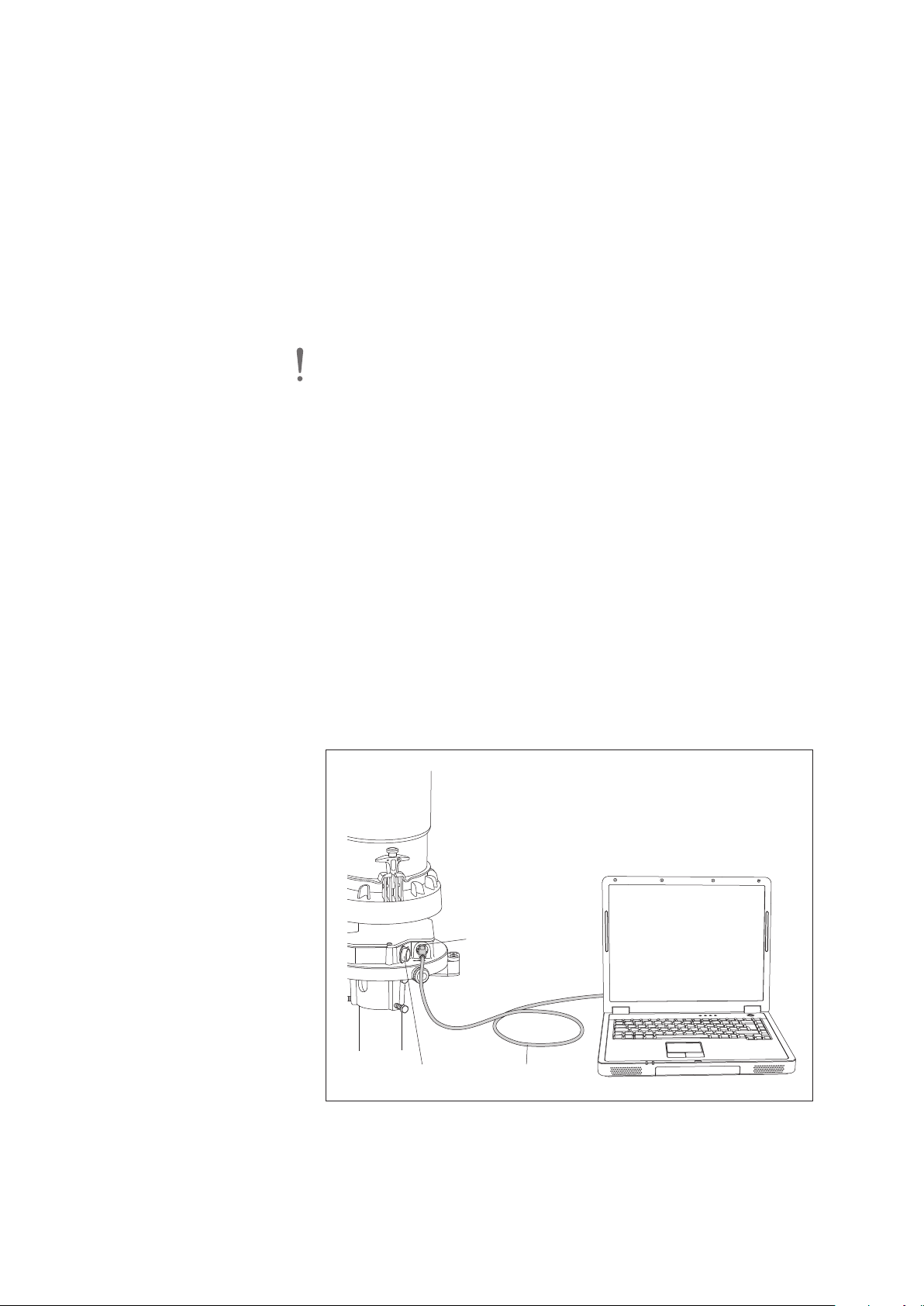
7.6 Performing the Guided Accuracy Test (check measurement)
USB interface
USB cable
Cover
2
The “OTT Pluvio
OTT Pluvio
S Software” flash drive is available as an accessory to the
2
S (refer to Appendix E).
In addition to the Operating Instructions (PDF file), USB interface driver, and OTT
datalogger example configurations, this flash drive includes the OTT Pluvio
2
ating Software. Alternatively, the individual files are found on our website
ww.ott.com/resources for free download.
w
sing the OTT Pluvio
U
formed. Using this test, the OTT Pluvio
2
perating Software, a Guided Accuracy Test may be per-
O
2
S can be easily and quickly checked for
proper operation on site.
In addition to this feature, other operations are provided by this Operating Software:
2
e.g. modify OTT Pluvio
S basic settings, start measurements, or update the
firmware.
Please note: Perform the Accuracy Test on calm days without precipitation!
(Otherwise, the test will be affected by wind and unwanted precipitation.) The USB
nterface also supplies operating voltage to the OTT Pluvio
i
2
. No additional
S
power supply is required. However, if present, it does not have to be removed.
Preparatory work
Prerequisite: PC (notebook) running Microsoft Windows 7 or later operating system.
䡵 Log on to the PC as an administrator
䡵 Installing the OTT Pluvio2Operating Software:
– copy the file “setup.exe” into a directory of the PC;
– start the file “setupe.exe” ➝ the “InstallShield Wizard” (installation program)
opens;
– follow the installation instructions on the screen.
䡵 Installing the USB interface driver (FTDI drivers):
1
)
– copy the file “CDM v2.12.00 WHQL Certified“
– remove the USB interface cover and connect the OTT Pluvio
into a directory of the PC;
2
S to the PC via
the USB cable (included); refer to Fig. 21;
– complete the device driver installation wizard that is automatically started;
1)
– start the file “CDM v2.12.00 WHQL Certified“
1)
or higher release
.
Oper-
Fig. 21: Connecting the OTT Pluvio2S
to the PC using the USB interface.
Once the PC supplies power to the
OTT Pluvio2S via the USB interface, a
green LED below the USB interface is lit.
42
Page 43

Performing the Guided Accuracy Test
䡵 Loosen the three knurled screws at the pipe housing.
Remove the pipe housing upwards.
䡵
䡵 Remove both spring-loaded terminals and carefully remove the collecting bucket.
䡵 Remove the USB interface cover and connect the OTT Pluvio2S to the PC via
the USB cable (included); refer to Fig. 21.
䡵 Start the OTT Pluvio2S Operating Software.
Select the “Connect” button ➝ the Operating Software will establish a con -
䡵
nection to the OTT Pluvio
2
S unit and retrieves different status information.
䡵 Select the “Guided Accuracy Test” button ➝ a wizard will guide you through
the accuracy test. Make sure you follow all the steps and notes shown on
he display!
t
䡵 After completing the accuracy test, remove the USB cable.
䡵 Replace the USB interface cover.
䡵 Empty the collecting bucket as necessary, reinstall it and secure it using the
two spring-loaded terminals; refer to Fig. 17.
䡵 Align the pipe housing and install it, refer to Fig. 20.
䡵 Retighten three knurled screws.
Please note: After attaching the USB interface, the OTT Pluvio
communication over the other interfaces!
2
S disconnects
43
Page 44
8 Repair
䡵 In case of a device malfunction, use Chapter 7.5 to see if you can resolve the
problem yourself.
䡵 In case of unit failure, please contact the OTT repair center:
OTT Hydromet GmbH
Repaircenter
Ludwigstrasse 16
87437 Kempten · Germany
Phone +49 831 5617-433
Fax +49 831 5617-489
[email protected]
2
Please note: Only have a defective OTT Pluvio
OTT repair center. Never attempt to repair the unit yourself! On no account carry
ut repairs yourself! Only a qualified repair followed by a factory final test ensures
o
the specified measurement accuracy. Any repairs or attempted repairs carried out
by the client will void any warranty.
After being properly trained, expressly authorized partner companies or clients
are allowed to perform repairs by replacement of components on their own. For
more information, please contact the OTT HydroService department.
S checked and repaired by the
9 Notes about the disposal of used units
Within the member countries of the European Union
In accordance with the European Union Directive 2002/96/EC, OTT takes old
devices back within the member countries of the European Union and disposes of
them properly. The devices concerned by this are marked with the symbol shown
aside.
䡵 For further information on the return procedure, please contact your local sales
contact. You will find the addresses of all sales partners in the internet on
“www.ott.com“. Please take into consideration also the national implementation
of the EU directive 2002/96/EC of your country.
For all other countries
䡵 Dispose of the OTT Pluvio2S properly after taking out of service.
䡵 Observe any applicable local regulations for the disposal of electronic devices!
䡵 Never put the OTT Pluvio2S into the normal household waste!
Materials used
Base plate: stainless steel/aluminium
Collecting bucket: ASA
Bucket support: ASA
Pipe housing: ASA
The material identification is found on the component itself for plastic parts.
44
Page 45

10 Technical Data
Supply voltage 5,5 … 28 VDC; typ. 12 VDC; reverse-polarity protected
Current consumption typ. 9.2 mA (measuring + communication) at 12 V
Power consumption ≤ 110 mW (without heater)
Recordable precipitation liquid, solid, mixed
Recordable precipitation amount 400 mm
Resolution
Intensity 0,001 mm/min or mm/h
Amount of precipitation 0,001 mm
Accuracy refer to limits/accuracy
DC
Measuring range
Bucket content 400 mm =
Collecting area 200 cm
^
8 l
2
(Ø 159.6
±0,1
mm)
Sampling interval (Poll) 1 minute … 60 minutes
Output delay
Real time < 1 minute
Non-real-time (filtered values) 5 minutes (max. collecting period is 60 minutes)
Interfaces
USB Version 2.0 (only for service purposes – no overload protection)
SDI-12 Version 1.3
RS-485 (2- or 4-wire) SDI-12 protocol and RS-485 command line mode; transfer speed
factory setting (RS-485): 9600 Baud; 8 N 1
Pulse output 2 or 5 Hz
Measured values/status values output IIntensity RT, Accu RT/NRT, Accu NRT, Accu total NRT, Bucket RT,
Bucket NRT, Temperature of load cell, OTT Pluvio2 S status,
Heater status
Supply voltage for orifice rim heater 12 … 28 V
; typ. 12/24 VDC; reverse-polarity protected
DC
(no isolation of the power supply for the orifice rim heating and
the precipitation gauge necessary)
Heater current consumption max. 2,2 A
Heater power at 12 V *: 12,5 Watt at 24 V: 50 Watt
* Temperature ramp of the orifice rim temperature restricted to
12 K (wind speed 0 m/s each)
Operating range of the orifice rim heater (ambient temperature) –40 … +60 °C
Measuring range of orifice rim temperature –40 … +85 °C
Target temperature for orifice ring rim +2 … +9 °C; factory setting +4 °C
Accuracy of target temperature ±1 °C
Dimensions Ø x h 288 mm x 651 mm
Weight (empty) approx. 7,8 kg
Housing material
Base plate stainless steel/aluminium
Collecting bucket ASA, UV resistant
Bucket support ASA, UV resistant
Pipe housing ASA, UV resistant
Degree of protection
Pipe housing closed IP 65
Pipe housing open IP 63
Load cell IP 67
Temperature range
Operation –40 … +60 °C
Storage –40 … +70 °C
Temperature compensation –25 … +45 °C
Max. wind speed without device damage 50 m/s
Relative humidity 0 … 100 %, non-condensing
EMV 2004/108/EG; EN 61326-1:2013
Salt resistance EN 60068-2-11
45
Page 46

Limits/accuracy
46
status 0 … 1024 1 <1
2
mm/min 0.000 … 50.000 0.100 0.001 ±0.1 ±1 % <1
Intensity RT mm/h 0.000 … 3000.000 6.000 0.60 ±6 ±1 % <1
Measured value Unit Measuring range Threshold Resolution Accuracy Accuracy Output
the larger value in each case counts minutes
absolute relative delay
SDI-12/RS-485 interface
Accu RT/NRT mm 0.000 … 500.000 0.030 0.001 ±0.1 ±1 % 1 … 65䊳Accu NRT mm 0.000 … 500.000 0.030 0.001 ±0.1 ±1 % 5 … 65䊳Accu total NRT mm 0.000 … 500.000 0.030 0.001 ±0.1 ±1 % 5 … 65䊳Bucket RT mm 7.000 … 400.000 0.001 ±0.1 ±0.2 % <1䊳Bucket NRT mm 7.000 … 400.000 0.001 ±0.1 ±0.2 % 5䊳Temperature of load cell °C –40.0 … +85.0 0.1 ±1 <1䊳Heater status 0 … 128 1 <1䊳OTT Pluvio
䊳
䊳
Temp. of electronics unit °C –40.0 … +85.0 0.1 ±1 <1䊳Power supply V +5.5 … +28.0 0.1 ±0.5 <1䊳Temp. of orifice ring rim °C –40.0 … +85.0 0.1 ±1 <1
䊳
Pulse status information 0 … 128 1 <1䊳Pulse-Accu RT-NRT mm
䊳
Pulse outputs
** Pulse factor: 0.05 ** Pulse factor: 0.1 ** Pulse factor: 0.2
– Output rate 2 Hz 0.05 … 6.0* / 0.1 … 12.0** / 0.2 … 24.0*** 0.1/0.2 ±0.1/0.2 ±1 % <1
– Output rate 5 Hz 0.05 … 15.0* / 0.1 … 30.0** / 0.2 … 60.0*** 0.1/0.2 ±0.1/0.2 ±1 % <1
Page 47
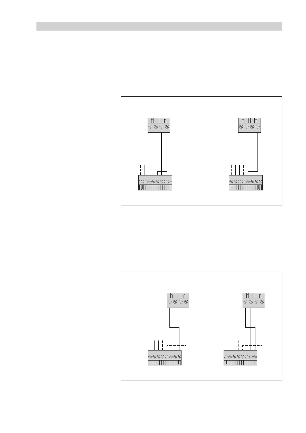
Appendix A – Connecting the OTT Pluvio2S to an OTT datalogger
+12 … +24 VDCGND
+12 … +24 V
DC
GND
S
DI-12
Input
A
4
31 2
OTT DuoSens
S
DI-12
Input
C
4
31 2
OTT netDL
OTT Pluvio
2
S
1 2 3 4 5 6 78
OTT Pluvio2 S
1 2 3 4 5 6 7 8
+12 … +24 VDCGND
+12 … +24 V
DC
GND
RS-485
Input
A
431 2
OTT DuoSens
RS-485
Input
C
431 2
OTT netDL
OTT Pluvio
2
S
1 2 3 4 5 6 7 8
OTT Pluvio2 S
1 2 3 4 5 6 7 8
A.1 Connecting the OTT Pluvio2S to an OTT netDL or OTT DuoSens
via SDI-12 or RS-485 interface
Method A: Connecting the OTT Pluvio
nd physical interface: SDI-12). The maximum length of the cable is 70 m!
a
䡵 Connect the OTT Pluvio2S to the OTT netDL IP datalogger or to the
OTT DuoSens Compact Datalogger as shown in Figure A1.
Also refer to the OTT netDL/OTT DuoSens Operating Instructions.
2
S via the SDI-12 interface (protocol
Fig. A1: Connecting the OTT Pluvio2S
to an OTT netDL or OTT DuoSens via
the SDI-12 interface.
The letters above the screw terminal strips
identify the connectivity options available
on the OTT netDL/OTT DuoSens.
For this application, only the 8-wire
screw terminal strip is needed.
2
Method B: Connect the OTT Pluvio
S using the physical RS-485 interface
(SDI-12 protocol via physical RS-485 interface). The maximum cable length
is 1000 m.
䡵 Connect the OTT Pluvio2S to the OTT netDL IP datalogger or to the
OTT DuoSens Compact Datalogger as shown in Figure A2.
Also refer to the OTT netDL/OTT DuoSens Operating Instructions.
Fig. A2: Connecting the OTT Pluvio2S to an
OTT netDL or OTT DuoSens via the RS-485
interface (SDI-12 protocol).
The letters above the screw terminal strips
identify the connectivity options available on
the OTT netDL/OTT DuoSens.
For this application, only the 8-wire
screw terminal strip is needed.
The GND connection represented
by the dashed line is necessary
only in case the OTT Pluvio
the OTT netDL/OTT DuoSens are
powered by separate power supplies.
2
S and
47
Page 48

Configuring the OTT netDL/OTT DuoSens for the OTT Pluvio2S
with SDI-12 interface
Create a OTT netDL/OTT DuoSens channel with “SDI-12 Master” or
䡵
“OTT SDI RS485” function block (“Serial sensors” tab).
䡵 Make the following settings:
Fig. A3: Setting the operating parameters
of the OTT netDL/OTT DuoSens SDI-12
Master function block.
The function block OTT SDI RS485
is set in the same way.
(Example shown: OTT DuoSens).
䊳
Terminal block OTT netDL “SDI-12 Master”: C 3-4 (specified)
OTT netDL “OTT SDI RS485”: C 1-2 (specified)
OTT DuoSens “SDI-12 Master”: A 3-4 (specified)
OTT DuoSens “OTT SDI RS485”: A 1-2 (specified)
Terminal block used (screw terminal strip) of the
OTT netDL/OTT DuoSens
䊳
Slave address SDI-12 bus address. Each slave address may be
assigned on an SDI-12 bus line only once. (Check/
set: refer to OTT netDL/OTT DuoSens Operating
Instructions, Chapter SDI-12 Transparent Mode.)
Typical setting: “0” (only one OTT Pluvio
nected to the terminal block, no bus operation).
䊳
Value no. identifies which value (the xth of n values + status
information) of the OTT Pluvio
2
S is recorded in this
channel. Typical setting: “1” (first one of nine (“M!”
Measuring Mode) or three (“M1!” Measuring Mode)
measured values)
䊳
Measuring mode “M!” or “M1!” (for allocating the measured values,
refer Chapter 6, “SDI-12 commands and responses”)
䊳
allocating the additional measured values of the
Value no./
Virtual Terminal ID
OTT Pluvio
2
S to virtual terminals (for allocating the
measured values, refer to Chapter 6, “SDI-12 commands and responses”).
䊳
Concurrent mode only for OTT netDL: refer to the operating program
online help.
䊳
Instantaneous value only for OTT netDL: refer to the operating program
online help.
2
S is con -
48
䡵 In the respective Channel function blocks, set the required units and number of
digits after the decimal place
Notes:
䊳
For recording all the 12 measured values + status information for an
OTT Pluvio
2
S, 12 channels in the OTT netDL/OTT DuoSens are thus necessary.
The first channel contains the function block “SDI-12 Master” or “OTT SDI RS485”
as the input signal. The other channels each contain a function block “Virtual
Sensor” (V02 to V09) as the input signal, (V03 in case of M1!). Of course, just
individual channels can also be recorded. In this case, there are fewer entries
required in the “Value no./Virtual Terminal ID” field.
䊳
Further information on the SDI-12 commands and responses used can be found
in Chapter 6, “SDI-12 commands and responses”.
䊳
The OTT Pluvio2S makes the measurement results available for retrieval
immediately after the aM! and aM1! SDI-12 commands.
Page 49
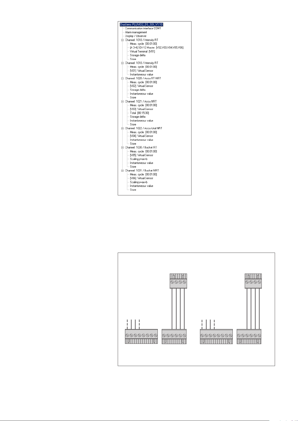
Fig. A4: Example configuration of an
+12 … +24 VDCGND
+12 … +24 V
DC
GND
Pulse
input
B
OTT Pluvio
2
S
Status
information
Precipitation
OTT Pluvio2 S
1 2 3 4 5 6
1 2 3 4
Pulse
input
D or E
OTT netDL OTT DuoSens
Status
information
Precipitation
1 2 3 4 5 6
1 2 3 4
1 2 3 4 5 6 7 8
1 2 3 4 5 6 7 8
OTT DuoSens with 6 values recorded.
Additional configuration examples
can be found on the flash drive
OTT Pluvio
2
S software.
2
A.2 Connecting the OTT Pluvio
S to an OTT netDL or OTT DuoSens
via the pulse output
䡵 Connect the OTT Pluvio2S to the OTT netDL IP datalogger or to the OTT DuoSens
Compact Datalogger as shown in Figure A5. Also refer to the OTT netDL/
OTT DuoSens Operating Instructions. Maximum cable length: 1000 m.
Fig. A5: Connecting the OTT Pluvio2S
to an OTT netDL or OTT DuoSens via
the pulse output.
The letters above the screw terminal
strips identify the connectivity options
available on the OTT netDL/OTT DuoSens.
One pulse input of the OTT netDL/DuoSens
is used in each case for the precipitation
amount and the status information.
49
Page 50
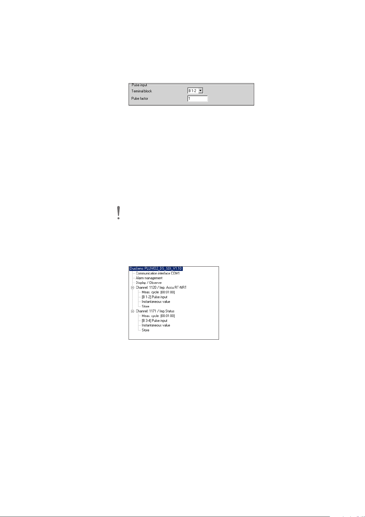
Configuring OTT netDL/OTT DuoSens for OTT Pluvio2S with pulse
output
Create two OTT netDL/OTT DuoSens channels with function block “Pulse input”
䡵
(“Digital sensors” tab). (When you only want to record the amount of precipitation, one function block is sufficient.)
䡵 Make the following settings:
Fig. A6: Setting the operating parameters
of the OTT netDL/OTT DuoSens
Pulse input function block
(example shown: OTT DuoSens).
䊳
Terminal block OTT netDL: D 1-2, D 3-4, E 1-2 or E 3-4
OTT DuoSens: B 1-2 or B 3-4
䊳
Pulse factor – amount of precipitation: 0.05 · 0.1 · 0.2 · 0.5 · 1.0
(one pulse corresponds to
0.05 mm, 0.1 mm, 0.2 mm,
0.5 mm or 1.0 mm of precipitation.)
– status information: 1
䊳
only for OTT netDL: time in milliseconds during which the
Debounce
delay [ms]
pulse input is disabled after recording a pulse. This prevents
the OTT netDL from recording unwanted pulses caused by
bouncing switch contacts. Set 8 ms for the OTT Pluvio
2
Please note:
䊳
Always position a pulse input at the beginning (top) of the function tree.
䊳
After changing the pulse factor, a data reset (reset the OTT netDL/OTT DuoSens)
is necessary!
䡵 In the “Channel” function block, set the required unit and number of digits after
the decimal place.
S.
Fig. A7: Example configuration of an
OTT DuoSens with 2 values recorded.
Additional configuration examples
can be found on the flash drive
OTT Pluvio2S software.
50
Page 51

Appendix B – Dimensions of the OTT Pluvio2S with pedestal and bottom plate
Optional empty
conduit pipe laying
Empty conduit pipe for connecting and earth cables
800 mm
Ø 253 mm (max. 288 mm)
0
Ø 159.6
±0,1
mm
2
00 cm
2
Concrete foundation
Pedestal with bottom plate
(Length: 424 mm, 624 mm, 924 mm)
1
0
00
1200 1500
|
|
4
24
6
24 924
| |
349
549 849
| |
392
592 892| |
I
nstallation height (orifice ring)
mm
mm
mm
mm
51
Page 52
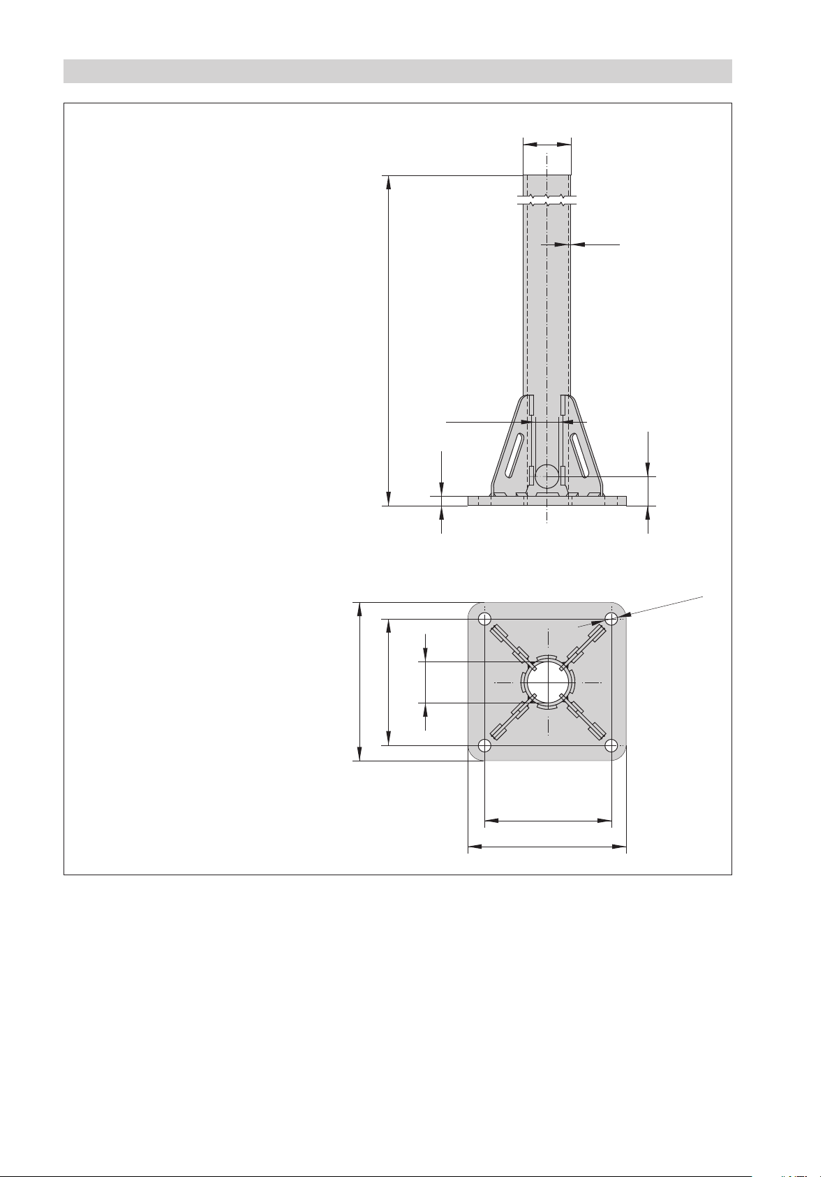
Appendix C – Dimensions of pedestal with bottom plate
A
±1
mm
Ø
60.3 mm
2
"
4 mm
12 mm
37 mm
200 mm
Ø 52.3 mm
160 mm
200 mm
160 mm
Ø
1
6
m
m
(
4
x
)
Ø 30 mm
Order numbers 1) 70.030.033.9.2
2)
70.030.034.9.2
3)
70.030.035.9.2
D
imensions A
I
nstallation height 1.0 m : 4 24 m m
1)
I
nstallation height 1.2 m : 6 24 m m
2)
Installation height 1.5 m : 9 24 m m
3)
52
Page 53
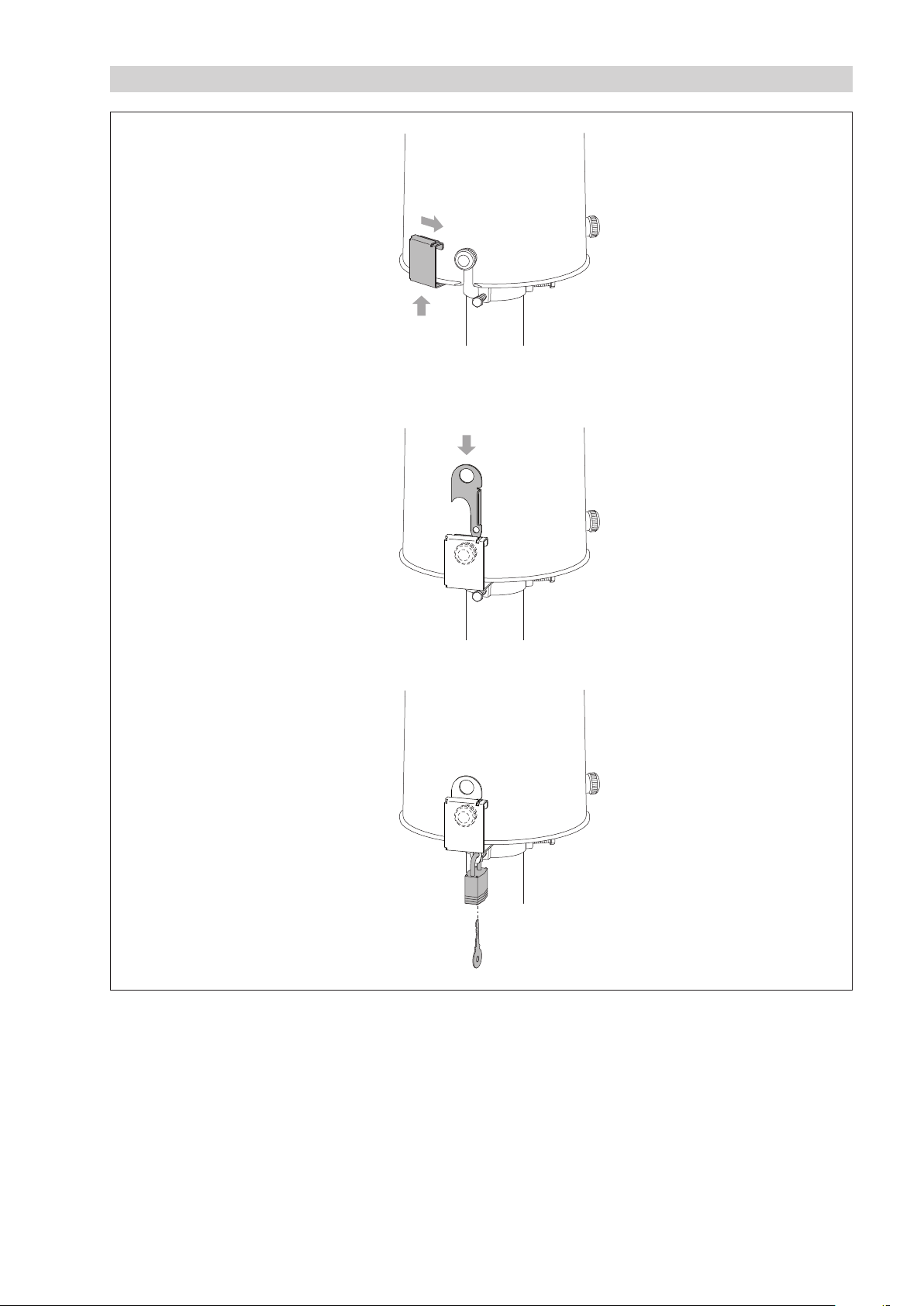
Appendix D – Installing the anti-theft protection
1.
2.
3.
4.
53
Page 54

Appendix E – Accessories/replacement parts
䊳
Accessories 2"-pedestal with bottom plate for 1.0 m installation height
– length 424 mm 70.030.033.9.2
– incl. bottom plate for attaching to a concrete foundation
– installation height (height of orifice ring): 1.0 m
2"-pedestal with bottom plate for 1.2 m installation height
– length 624 mm 70.030.034.9.2
– incl. bottom plate for attaching to a concrete foundation
– installation height (height of orifice ring): 1.2 m
2"-pedestal with bottom plate for 1.5 m installation height
– length 924 mm 70.030.035.9.2
– incl. bottom plate for attaching to a concrete foundation
– installation height (height of orifice ring): 1.5 m
Mounting kit for 2" pedestal 99.020.083.9.2
– for attaching the 4" pedestal to a concrete foundation
– 4 x compound anchor cartridge
– 4 x anchor rod M 12
– 4 x hexagon nut M 12 + washer
Wind shield OTT PWS …
– … 100 for 1.0 m installation height 70.035.020.1.2
– … 120 for 1.2 m installation height 70.035.021.1.2
– … 150 for 1.5 m installation height 70.035.022.1.2
Wind shield mounting kit OTT PWS … 99.020.081.9.2
– for attaching the wind shield to a concrete foundation
– 4x compound anchor cartridge
– 4x anchor rod M 10
– 4x hexagon nut M 10 + washer
OTT POD 100 platform 70.035.030.2.2
– for use with OTT PWS 100 or OTT PWS 150 wind shields
2
for OTT Pluvio
S installation heights of 2.0 or 2.5 m
– height: 1 m
Mounting kit for OTT POD 100 platform 99.020.082.9.2
– for attaching the platform to a concrete foundation
– 4x compound anchor cartridge
– 4x anchor rod M 16
– 4x hexagon nut M 16 + washer
24 V
power supply for C-rail mounting
DC
– 50 W 65.030.001.9.2
– degree of protection: IP 20
– for C-rail mounting
– input voltage: 90 … 260 V
AC
24 VDCpower supply in separate protective casing
– 50 W 97.850.012.9.5
– degree of protection: IP 65
– aluminium protective casing
– input voltage: 90 … 260 V
AC
Cable for OTT Pluvio2S without heater 97.000.039.9.5
– twisted pair configuration
– PUR, gray
– 2 x 2 x 0.50 mm
2
– shielded
2
Cable for OTT Pluvio
S with heater 97.000.038.9.5
– special PUR, gray
– 7 x 0.75 mm
2
– shielded
54
Page 55

OTT Pluvio2S software flash drive 56.575.001.9.7
– incl. USB interface drivers
– incl. OTT Pluvio
2
perating software
o
– incl. example configurations for the OTT datalogger
Anti-freeze 0.929.002.002
– POWERCOOL DC 924-PXL
– package size: 10 litre canister
Anti-theft protection for OTT Pluvio² S 70.030.040.9.2
U-lock (weather-resistant) for anti-theft protection 99.000.083.9.5
Test weight kit 70.020.071.9.2
– tare weigh 2.5 kg ± 100 g
– test weight 200 g M1
– DKD certificate for test weigh
– in transport box
䊳
eplacement
R
parts
Collecting bucket 70.030.401.1.1
USB cable 97.970.065.9.5
– USB connector type A to USB type B, 3 m
55
Page 56

Document number
70.030.001.B.E 04-0119
OTT HydroMet GmbH
Ludwigstrasse 16
87437 Kempten · Germany
Tel. +49 831 5617-0
Fax +49 831 5617-209
[email protected] · www.ott.com
 Loading...