


Operating instructions
IP Datalogger
OTT netDL 500
OTT netDL 1000
English
We reserve the right to make technical changes and improvements without notice.

Table of contents
1 |
Scope of supply |
5 |
|
2 |
Order numbers and version code |
5 |
|
3 |
General safety information |
7 |
|
4 |
About these operating instructions |
8 |
|
5 |
Introduction |
9 |
|
|
5.1 |
Overview of the OTT netDL IP datalogger |
12 |
6 |
Overview: Starting up the OTT netDL unit |
14 |
|
7 |
Installing the OTT netDL unit |
15 |
|
|
7.1 |
Attaching the OTT netDL unit |
15 |
|
7.2 |
Locations of the screw terminal strips and RS-232 interfaces |
17 |
|
7.3 |
Connecting sensors having an RS-485 interface (2-wire) |
18 |
|
7.4 |
Connecting sensors having an SDI-12 interface |
18 |
|
7.5 |
Connecting sensors having a pulse output |
19 |
|
7.6 |
Connecting equipment having a status output |
19 |
|
7.7 |
Connecting sensors having a voltage output |
20 |
|
7.8 |
Connecting sensors having a current output |
20 |
|
7.9 |
Connecting the Pt 100 temperature sensor |
21 |
|
7.10 |
Connecting sensors having a potentiometer (5 kOhms) |
21 |
|
7.11 |
Connecting sensors having an RS-232 interface |
22 |
|
7.12 |
Connecting switching contacts |
22 |
|
7.13 |
Connecting 4-20 mA outputs |
23 |
|
7.14 |
Connecting status outputs |
23 |
|
7.15 |
Connecting the power supply to the OTT netDL unit |
24 |
|
7.16 |
Connecting the GSM cellular radio antenna and inserting the SIM card |
24 |
|
7.17 |
Connecting external communication equipment |
25 |
|
7.18 |
Connecting an Ethernet LAN or DSL router |
26 |
8 |
Setting OTT netDL operating parameters |
27 |
|
|
8.1 |
Installing the OTT netDL operating program |
27 |
|
8.2 |
Establishing the PC/OTT netDL communication link |
27 |
|
8.3 |
If required: Installing the USB interface driver |
28 |
|
8.4 |
Introduction: Setting OTT netDL operating parameters |
29 |
9 |
Operating/configuring the OTT netDL unit on site |
30 |
|
|
9.1 |
Determining and displaying instantaneous values (Observer function) |
30 |
|
9.2 |
Entering observer texts (extended Observer function) |
32 |
|
9.3 |
Scaling instantaneous values/stored values (set offset) |
33 |
|
9.4 |
Displaying/setting date and time |
33 |
|
9.5 |
Entering manual values into a manual sensor |
34 |
|
9.6 |
Displaying information on transmissions |
35 |
|
9.7 |
Displaying information on connections |
35 |
|
9.8 |
Displaying system information |
36 |
10 |
LED indicators |
37 |
|
3
11 |
Reading out measured data on site |
38 |
|
12 |
Updating the OTT netDL firmware |
39 |
|
13 |
Overview: Alarm and action management |
40 |
|
14 |
Protecting the OTT netDL unit using a password |
41 |
|
15 |
Deleting the data memory |
42 |
|
16 |
Setting date and time |
42 |
|
17 |
Printing the connection diagram |
43 |
|
18 |
SDI-12 transparent mode |
44 |
|
19 |
Error messages |
45 |
|
|
19.1 |
Internal error messages |
45 |
|
19.2 |
External error messages |
45 |
|
19.3 |
Sensor error messages |
45 |
|
19.4 |
Processing module error messages |
46 |
20 |
Maintenance |
47 |
|
21 |
Repair |
47 |
|
22 |
Note on the disposal of old units |
48 |
|
23 |
Technical data |
49 |
|
Appendix A: OTT netDL 1000 IP Datalogger Declaration of Conformity |
52 |
||
4

1 Scope of supply
OTT netDL 500 |
– |
1 |
IP datalogger incl. 4 physical input channels (1 x RS-485, 1 x SDI-12, |
OTT netDL 1000 |
|
|
2 x pulse/status (OTT netDL 1000: 4 x), 2 switching outputs, RS-232 interface |
|
|
|
(OTT netDL 1000: 2 x), USB host/USB device interface, Ethernet interface |
|
|
|
(RJ-45) (OTT netDL 1000), power supply/ground connector, 4 MB measurement |
|
|
|
memory, LCD display, 2 status LEDs and jog shuttle; incl. two (OTT netDL 500) |
|
|
|
or three (OTT netDL 1000) slots for expansion cards; optional GSM quadband |
|
|
|
modem (version code "B x x" or "Cx x") |
|
– |
1 universal power supply connector kit |
|
|
– 1 |
OTT netDL Software CD-ROM |
|
|
– |
1 operating instructions |
|
|
– |
1 |
factory acceptance test (FAT) certificate |
2 Ordering numbers and version code |
|
|
OTT netDL 500 |
IP datalogger |
55.553.001.9.0 |
|
incl. two slots for expansion cards |
|
|
– Standard version |
A x x |
|
– Standard version + GSM modem |
B x x |
|
– Standard version + GSM modem + voice anouncer 1) |
C x x |
OTT netDL 1000 |
IP datalogger |
55.552.001.9.0 |
|
incl. three slots for expansion cards |
|
|
– Standard version |
A x x x |
|
– Standard version + GSM modem |
B x x x |
|
– Standard version + GSM modem + voice anouncer 1) |
C x x x |
Expansions |
Analog input card |
|
|
2 inputs for analog input signals |
|
|
– 0-20 mA / 4-20 mA |
|
|
– 0-50 mV / 0-1.25 V / 0-5 V / 0-10 V |
|
|
– Potentiometer, 5 kOhms |
|
|
– Pt 100 |
|
|
Analog input card, galvanically isolated |
2 |
|
Same input signals as for analog input card (see above) |
|
|
RS-232 input card |
3 |
|
for OTT sensors with RS-232 interface |
|
|
Output card |
4 |
|
Galvanically isolated output signals |
|
|
– 2 outputs (4-20 mA) |
|
|
– 4 status outputs (4 x 1 bit; 100 mA) |
|
|
Barometric input card |
5 |
|
For connecting a maximum of two pressure probes |
|
|
containing Keller absolute pressure cells |
|
1) These device versions are expected to be available in Q2/2012
5
Version code |
OTT netDL 500 |
|
|
|
C . .1) |
|
|
|
Device versions: |
|
A . . |
B . . |
|
|
|
|
– without expansion cards: |
.00 |
|
|
|
|
|
|
– with one expansion card: |
.10 |
.20 |
.30 |
.40 |
.50 |
|
|
– with two expansion cards: |
.11 |
.22 |
.33 |
.44 |
.55 |
|
|
|
|
.12 |
.23 |
.34 |
.45 |
|
|
|
|
.13 |
.24 |
.35 |
|
|
|
|
|
.14 |
.25 |
|
|
|
|
|
|
.15 |
|
|
|
|
|
OTT netDL 1000 |
|
|
|
|
|
|
|
|
|
|
|
|
|
|
|
Device versions: |
|
A . . . |
B . . . |
C . . .1) |
|
|
|
– without expansion cards: |
.000 |
|
|
|
|
|
|
– with one expansion card: |
.100 |
.200 |
.300 |
.400 |
.500 |
|
|
– with two expansion cards: |
.110 |
.220 |
.330 |
.440 |
.550 |
|
|
|
|
.120 |
.230 |
.340 |
.450 |
|
|
|
|
.130 |
.240 |
.350 |
|
|
|
|
|
.140 |
.250 |
|
|
|
|
|
|
.150 |
|
|
|
|
|
– with three expansion cards: |
.111 |
.222 |
.333 |
.444 |
.555 |
|
|
|
|
.112 |
.223 |
.334 |
.445 |
|
|
|
|
.113 |
.224 |
.335 |
.455 |
|
|
|
|
.114 |
.225 |
.244 |
|
|
|
|
|
.115 |
.233 |
.245 |
|
|
|
|
|
.122 |
.234 |
.255 |
|
|
|
|
|
.123 |
.235 |
|
|
|
|
|
|
.124 |
.244 |
|
|
|
|
|
|
.125 |
.245 |
|
|
|
|
|
|
.133 |
.255 |
|
|
|
|
|
|
.134 |
|
|
|
|
|
|
|
.135 |
|
|
|
|
|
|
|
.144 |
|
|
|
|
|
|
|
.145 |
|
|
|
|
|
|
|
.155 |
|
|
|
|
|
Examples |
|
|
|
|
|
|
|
OTT netDL 1000 standard version; |
|
|
|
|
|
|
|
2 RS-232 input cards, 1 barometric input card |
|
|
|
|||
|
Ordering number: |
55.552.001.9.0 |
|
|
|
|
|
|
Version code: |
A335 |
|
|
|
|
|
|
OTT netDL 500 standard version + GSM modem; |
|
|
|
|||
|
1 analog input card, 1 output card |
|
|
|
|
|
|
|
Ordering number: |
55.553.001.9.0 |
|
|
|
|
|
|
Version code: |
B14 |
|
|
|
|
|
1) These device versions are expected to be available in Q2/2012.
Accessories |
Modem connection cable |
97.961.069.9.5 |
|
– 1.5 meters, 9-pin Sub-D socket/ |
|
|
9-pin Sub-D plug |
|
|
OTT netDL/PC data transfer cable |
97.961.068.9.5 |
|
– 1.5 meters, 9-pin Sub-D socket/ |
|
|
9-pin Sub-D socket |
|
|
USB connection cable |
97.970.065.9.5 |
|
– USB connector type A to USB connector type B, 3 m |
|
|
Flat antenna for GSM modem |
97.980.060.9.5 |
6

3General safety information
Read these operating instructions before using the OTT netDL for the first time! Become completely familiar with the installation and operation of the OTT netDL and its accessories!
Note any additional information on dangers given within the individual work steps.
Only use the OTT netDL and its accessories in the manner described in these operating instructions.
Make sure that the installation site is sufficiently protected against moisture (IP 41 type of protection)!
Select the installation site so that the ambient temperature never exceeds or falls below the allowable temperature range of –40 °C to +70 °C (for device versions B . . . and C . . . : –30 °C to +70 °C)!
Install the OTT netDL in a closed control cabinet or in a fire protection cabinet! If the power supply of OTT netDL is a low power source (LPS), this is not necessary.
Do not open the OTT netDL unit! Sensors, communication equipment, power supply, switching contacts, or additional components are connected only through the screw terminal strips/9-pin Sub-D connectors accessible from outside.
Operate an OTT netDL unit with built-in GSM modem (device versions B . . .
and C . . .) only with the GSM cellular radio antenna connected. Minimum clearance between antenna and unit: 20 cm!
Before connecting the power supply, check that all wires are properly attached to the screw terminal strips and/or 9-pin Sub D connectors.
It is essential to comply with the electrical limits given in the "Technical Data" section.
Connect the OTT netDL only to a power supply providing less than 28 V DC. Protect the feed line of the supply voltage with a safety fuse (10 A / fast)!
Always use a galvanically isolated safety extra-low voltage (SELV) for mains supply.
Do not make any changes or retrofits to the OTT netDL!
Have a defective OTT netDL checked and repaired by the OTT repair center. Under no circumstances carry out any repairs yourself.
Caution: With a nearly full data memory in the OTT netDL unit, it may take a few minutes after an interruption of the operating voltage until communication is possible again!
7
4 About these operating instructions
These operating instructions (revision "01-0811") cover the OTT netDL software versions
OTT netDL firmware (operating system) |
from V 2.50.0 |
OTT netDL operating program |
from V 1.50.0 |
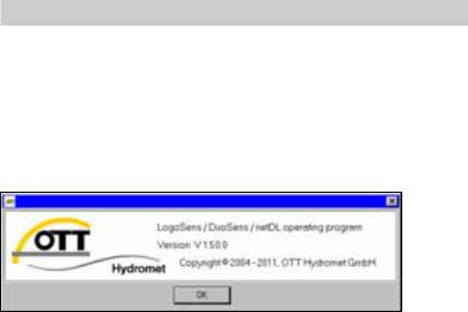
The version of the OTT netDL operating program can be found via the "Info" feature in the "Help" menu.
The version of the OTT netDL firmware is found in the master data window (refer to online help) after the OTT netDL configuration has been read into the operating program.
In Chapter 12 "Updating the OTT netDL firmware" you will find a description on how to update the OTT netDL firmware.
8

5 Introduction
The OTT netDL unit is a datalogger that is especially designed for hydrometry, meterology and environmental measuring technology.
The standard version of the unit has four physical input channels, an LCD display, and a jog shuttle. (The jog shuttle is a special operating button that can be rotated and pressed.) On request, the OTT netDL is available with various expansion cards and a built-in GSM modem. Additionally, OTT netDL 1000 has an Ethernet interface as well as a second serial interface.
Plug-in screw terminal strips allow easy connection of sensors and power supply without having to open the unit. Two LEDs show the operating states of the datalogger as well as of the GSM modem.
Configuration and parametrization are carried out using the "OTT netDL operating program" PC software. This software allows the system to be conveniently and flexibly tailored to a wide range of measurement requirements of a station.
All inputs are equipped with an internal overvoltage protection. The very low power consumption allows the unit to be operated with solar power without problem.
Using the internal or external GSM modem (cellular radio modem), remote data communication as well as remote parametrization may be done over the GSM cellular radio network (GSM = Global System for Mobile Communications). The remote data communication can be optionally carried out via a dial-up telephone connection, by SMS text messages, or using the packet-based GPRS mobile radio transmission service (General Packet Radio Service). The OTT netDL 1000 unit provides remote data communication through the Ethernet interface. Similarly, remote data communication may be carried out via a satellite transmitter or a cable modem.
Furthermore, the OTT netDL has individually configurable alarm and action management: If particular events occur, OTT netDL independently generates an alarm and sends this via a modem e.g. to a control center. It is also possible to control external devices via switching contacts.
9
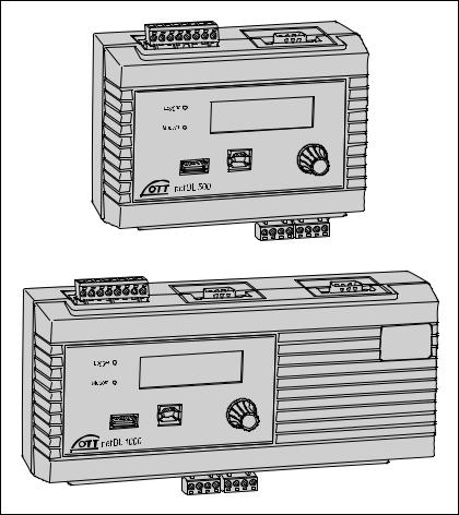
Fig. 1: OTT netDL IP datalogger
Top: OTT netDL 500 Bottom: OTT netDL 1000
10
Fig. 2: Front of the OTT netDL unit with the status LEDs, USB interfaces (left: Host; right: Device), and the plug-in screw terminal strips.
The figure shows the OTT netDL 500 unit including two expansion cards and internal GSM modem and the OTT netDL 1000 standard version without any expansion cards.
|
Jog shuttle |
SIM card holder |
GSM antenna |
|
connector |
USB interfaces |
LCD display |
Plug-in screw terminal strips |
|
for connecting sensors |
|
11
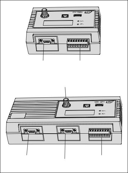
Fig. 3: Rear panels of the OTT netDL units including the screw terminal strips for power supply and switching contacts.
Serial interface |
Plug-in screw terminal strip |
||
(RS-232/COM 1) |
for voltage supply |
||
|
|
and switching contacts |
|
|
|
Jog shuttle |
|
Serial interface |
|
|
Plug-in screw terminal strip |
(RS-232/COM 2) |
Serial interface |
for voltage supply |
|
for extended communication |
(RS-232/COM 1) |
and switching contacts |
|
5.1 Overview of the OTT netDL IP datalogger
Sensor inputs
RS-485 interface (e.g. OTT RLS radar sensor, Sonicflow)
SDI-12 interface (e.g. Hydrolab DataSonde DS5, Hydrolab MiniSonde MS5)
Pulse input
Status input (2 x 1 bit)
0-50 mV, 0-1.25 V, 0-5 V, 0-10 V voltage input *
(0) 4-20 mA input (current loop) *
Pt 100 (temperature sensor) *
5 kOhm potentiometer *
RS-232 interface (OTT protocol, e.g. Nimbus bubble sensor) *
* only with analog/RS-232 expansion
Communication interfaces
RS-232 interface
USB host interface
USB device interface
Ethernet interface
12
Communication protocols
OTT protocol
OTT HDR / OTT HDR 1200 (satellite communication)
CREX code (satellite communication)
Terminal mode
SDI-12 transparent mode
FTP (File Transfer Protocol)
SMTP (Simple Mail Transfer Protocol)
HTTP GET / HTTP POST (Hypertext Transfer Protocol)
Outputs
Potential-free switching output (with output card)
Voltage output for supply of sensors (switched Ubat)
The outputs switch e.g. modem, sensor supply, or alarm devices (potential-free switching output via relay).
Measured value processing
Sample interval
Mean calculation
Totals formation
Scaling "ax + b"
Two-point scaling
Delta storage
Definition of a sensor delay time
Extreme value collection (minimum/maximum)
Filter functions
Extreme value recording
Virtual terminal/virtual sensor (logical channels)
Linearization table
Arithmetic function
Alarm management: Limit monitoring (threshold/gradient); status alarm
Reading out/data transmission
Reading out on site via RS-232 and USB interface
Reading out via modem
Independent data transmission via modem, terminal adapter, or satellite transmitter
ISDN D channel data transmission possible (X.31)
Independent transmission of alarm messages via SMS (e-mail/fax)
Control elements
LCD display and jog shuttle
13

6 Overview: Starting up the OTT netDL unit
Starting up a OTT netDL unit is done in a maximum of 10 steps:
1. |
Device versions "B . . ." and "C . . .": |
Refer to chapter |
|
||
|
Inserting the SIM card |
7.16 |
2. |
Attaching the datalogger |
7.1 |
3. |
Connecting sensors |
from 7.2 |
4. |
Connecting switching contacts* |
7.12 |
5. |
Connecting 4-20 mA outputs* |
7.13 |
6. |
Connecting status outputs* |
7.14 |
7. |
Connecting the power supply |
7.15 |
8. |
Device versions "B . . ." and "C . . .": |
|
|
Connecting the GSM cellular radio antenna |
7.16 |
9. |
Installing and connecting external communication equipment* |
7.17 |
10. |
OTT netDL 1000: Connecting an Ethernet LAN or DSL router* |
7.18 |
11. |
Configuring the datalogger and setting operating parameters |
8 |
(also refer to the online help of the OTT netDL operating program) * Only if required
14
7 Installing the OTT netDL unit
7.1 Attaching the datalogger
Requirements of the intended installation site:
Sufficient protection from moisture (IP 41 protection type).
Properly determined space for the electrical cables.
The following operating temperature ranges are kept: Device version A . . : –40 °C up to +70 °C
Device versions B . . and C . . : –30 °C up to +70 °C
Standard top hat rail (TS 35) mounted at installation site.
Closed control cabinet or fire protection cabinet.
(not required if the power supply of OTT netDL is a low power source)
The dimensions of the OTT netDL can be found in Fig. 5.
Caution: Do not open the OTT netDL unit during installation! There are no adjustment or operating elements or connecting means inside the housing.
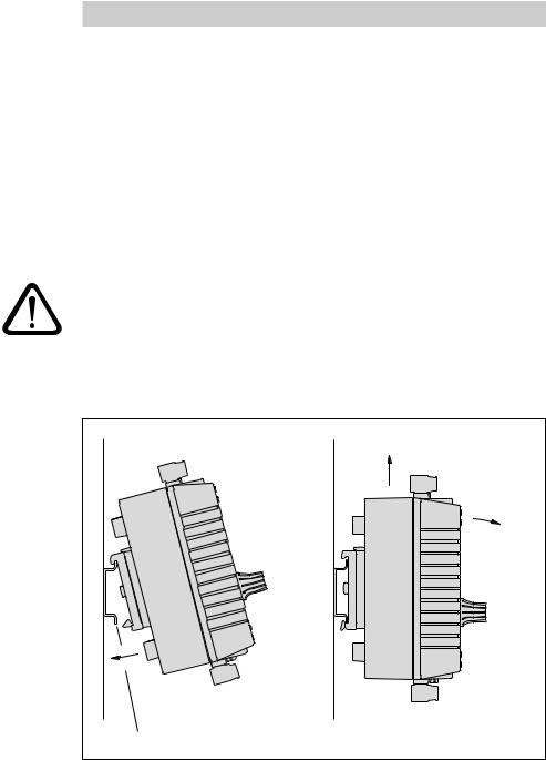
Engage the OTT netDL unit into the top hat rail as shown in Figure 4 (left). Press the underside of the OTT netDL unit against the top hat rail until it clicks into place.
Fig. 4: Fastening the OTT netDL unit to the top hat rail (left)/removing it from the rail (right).
Top hat rail
Removing the OTT netDL unit: Carefully push the unit a few millimeters upward, slightly tilt the underside towards your body, and then remove it from the top hat rail, refer to Figure 4 (right).
15
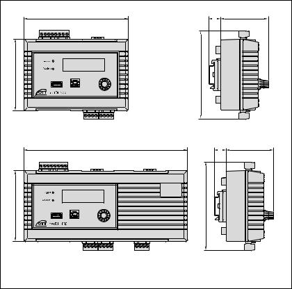
Fig. 5: OTT netDL unit dimensions; Top: OTT netDL 500 Bottom: OTT netDL 1000
148 |
18 |
68 |
102 |
124 |
|
232 |
18 |
68 |
102 |
124 |
|
|
all dimensions in mm |
|
16
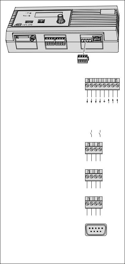
7.2Overview of the locations of the screw terminal strips and RS-232 interfaces
Fig. 6: Available positions for the plug-in screw terminal strips.
The figure shows the OTT netDL 1000 unit without expansion cards.
Factory configuration (without expansion cards):
OTT netDL 500: C, D + O-P OTT netDL 1000: C-E + O-P
The specific configuration of your unit including expansion cards as well as the positions of the screw terminal strips/ RS-232 interfaces can be obtained from the Factory Acceptance Test (FAT) Certificate attached.
Please note: protect the feed line of the voltage supply (screw terminal strip N, contacts 6, 7 and 8) with a safety fuse (10 A / fast)!
OTT netDL … |
500 |
1000 |
|
|
|
|
|
|
|
|
Voltage supply/ |
|
|
|
|
|
|
|
|
|
|
switching contacts1) |
|
|
|
|
|
|
|
|
|
|
Screw terminal strip |
N |
N |
1 |
2 |
3 |
4 |
5 |
6 |
7 |
8 |
|
|
|
1 0 V |
Bat |
2 0 V |
Bat |
|
(GND) |
(GND) |
+12 V) |
|
|
|
1 U |
2 U |
|
|||||
|
|
|
Switching contact |
Switching contact |
Switching contact |
Switching contact |
|
0 V |
0 V |
(typ. |
|
|
|
|
Bat |
Bat |
Bat |
||||
|
|
|
|
U |
U |
U |
||||
Connection of sensors |
|
|
|
|
|
|
|
|
|
|
Screw terminal strip |
C, D + |
C … E + |
|
|
|
|
|
|
|
|
|
G … K 2) |
G … M 2) |
1 2 3 4 |
|
|
|
|
|||
4-20 mA outputs |
|
|
|
|
|
|
|
|
|
|
Screw terminal strip |
S-T; U-V |
S-T; U-V; W-X |
|
|
|
|
|
|
|
|
|
|
|
1 |
2 |
3 |
4 |
|
|
|
|
Status outputs |
|
|
|
|
|
|
|
|
|
|
Screw terminal strip |
G-H; J-K |
G-H; J-K; L-M |
|
|
|
|
|
|
|
|
|
|
|
1 |
2 |
3 |
4 |
|
|
|
|
RS-232 interfaces |
|
|
|
1 |
|
5 |
|
|
|
|
Communication COM 1 |
O-P |
O-P |
|
|
|
|
|
|
||
|
6 |
|
9 |
|
|
|
|
|||
COM 2 |
– |
Q-R |
|
|
|
|
|
|
||
|
|
|
|
|
|
|
|
|||
Serial sensor input3) |
G-H; J-K |
G-H; J-K; L-M |
|
|
|
|
|
|
|
|
|
|
|
1 DCD |
6 DSR |
|
|
|
|||
|
|
|
2 RXD |
7 RTS |
|
|
|
|
||
|
|
|
3 TXD |
8 CTS |
|
|
|
|
||
1) max. 5 A |
|
|
4 |
DTR |
9 |
RI |
|
|
|
|
|
|
5 GND |
|
|
|
|
|
|
||
2) G … K + G … M only with expansion cards |
|
|
|
|
|
|
|
|||
|
|
|
|
|
|
|
|
|
||
3) only with RS-232 imput card |
|
|
|
|
|
|
|
|
|
|
|
|
|
|
|
|
|
|
|
|
17 |
 Loading...