


VS 2001
Vehicular Radio Terminal
User’s Guide
779-0217/03.04

VS 2001 Vehicular Radio Terminal
User’s Guide
All copyright and industrial rights in this document and in the technical
knowledge it contains are owned by OTE and/or the third parties
rightfully concerned.
No part of this document nor any data herein shall be disclosed,
reproduced or used for any purpose whatsoever without the prior
written consent of OTE as foreseen by the law. Drawings and specifications are subject to change. All trademarks and registered trademarks are the property of their respective holders. Printed in Italy.
OTE S.p.A.
A Finmeccanica Company
Via E. Barsanti 8, 50127 - Firenze, Italy
Phone: +39 55 43811, Fax: +39 55 4381426
BL: TETRA 3.1.7.0
BQ 48001A (TMO)
SWR:
2 779-0217/03.04
BQ 43000A (DMO)
VS 2001 Vehicular Radio Terminal
User’s Guide
Before using the equipment, read all the
instructions contained in the manual and,
with special care, those relative to safety .
Lue käyttöohjeet ja erityisesti turvallisuuteen
liittyvat ohjeet ennen koneiston käyttöä.
Alvorens over te gaan tot het gebruik van het
apparaat lees met aandacht al de instructies
van het handboek en let vooral op die die de
veiligheid betreffen.
Alvorens het apparaat in gebruik te nemen
lees alle instructies van het handboek en
vooral de voorschriften betreffende de
veiligheid.
Avant toute utilisation de l’appareil, lire
toutes les indications contenues dans le
Manuel et avec une attention particulière
celles relatives à la sécurité.
Läs alla instruktioner i denna manual innan
ni använder apparaten och då särskilt
noggrannt de anvisningar som gäller
säkerheten.
Læs alle de vejledninger, der er indeholdt i
manualen med særlig opmærksomhed på de
vejledninger, der vedrører sikkerheden, før
apparatet tages i brug.
Vor Gebrauch des Geräts alle in dieser
Bedienungsanleitung enthaltenen
Anweisungen und Vorschriften lesen.
Den Sicherheitsbestimmungen ist dabei
besondere Aufmerksamkeit zu widmen.
779-0217/03.04 3

VS 2001 Vehicular Radio Terminal
User’s Guide
Πριν χρησιµοποιήσετε τη συσκευή
διαβάστε όλες τις οδηγίες που περιέχονται
στο εγχειρίδιο και δώστε ιδιαίτερη προσοχή
στης οδηγίες ασφαλείας.
Prima di utilizzare l’apparecchiatura leggere tutte le indicazioni contenute nel manuale e con particolare attenzione quelle relative alla sicurezza.
Antes de utilizar el equipo leer todas las
instrucciones contenidas en el manual,
poniendo particular atención a las de
seguridad.
Antes de utilizar o aparelho, leia todas as
instruções que constam no manual e com
muita atenção as instruções relativas à
segurança.
Перед использованием оборудования
ознакомиться с руководством по
пользованию, придавая особое
внимание инструкциям по мере
безопасности.
4 779-0217/03.04

VS 2001 Vehicular Radio Terminal
User’s Guide
This equipment is marked
According to the requirements specified in the R&TTE directive 1999/5/EC and the Commission Decision 6th April 2000,
the EC marking is accompanied by the Class II equipment
class identifier.
This equipment is intended for sell and use in Austria, Belgium, Denmark, Finland, France, Germany, Greece, Ireland,
Italy, Luxembourg, Portugal, Spain, Sweden, The Netherlands, United Kingdom.
This equipment requires authorization or license for use.
This equipment operates on frequency bands non-harmoni-
sed in the EU.
This equipment can also be used worldwide where the equi-
pment is approved for use.
779-0217/03.04 5


VS 2001 Vehicular Radio Terminal
User’s Guide
Hereby, OTE S.p.A., declares that this VS 2001 is in compliance with the essential requirements and other relevant
provisions of Directive 1999/5/EC.
OTE S.p.A. vakuuttaa täten että VS 2001 tyyppinen laite on
direktiivin 1999/5/EY oleellisten vaatimusten ja sitä koskevien direktiivin muiden ehtojen mukainen.
Hierbij verklaart OTE S.p.A. dat het toestel VS 2001 in overeenstemming is met de essentiële eisen en de andere relevante bepalingen van richtlijn 1999/5/EG.
Bij deze verklaart OTE S.p.A. dat deze VS 2001 voldoet aan
de essentiële eisen en aan de overige relevante bepalingen
van Richtlijn 1999/5/EC.
Par la présente, OTE S.p.A. déclare que ce VS 2001 est conforme aux exigences essentielles et aux autres dispositions de
la directive 1999/5/CE qui lui sont applicables.
Härmed intygar OTE S.p.A. att denna VS 2001 står I överens-
stämmelse med de väsentliga egenskapskrav och övriga relevanta bestämmelser som framgår av direktiv 1999/5/EG.
Undertegnede OTE S.p.A. erklærer herved, at følgende udstyr
VS 2001 overholder de væsentlige krav og øvrige relevante
krav i direktiv 1999/5/EF.
Hiermit erklärt OTE S.p.A. die Übereinstimmung des Gerätes
VS 2001 mit den grundlegenden Anforderungen und den
anderen relevanten Festlegungen der Richtlinie 1999/5/EG.
ΜΕ ΤΗΝ ΠΑΡΟΥΣΑ OTE S.p.A. ∆ΗΛΩΝΕΙ ΟΤΙ VS 2001
ΣΥΜΜΟΡΦΩΝΕΤΑΙ ΠΡΟΣ ΤΙΣ ΟΥΣΙΩ∆ΕΙΣ ΑΠΑΙΤΗΣΕΙΣ ΚΑΙ
ΤΙΣ ΛΟΙΠΕΣ ΣΧΕΤΙΚΕΣ ∆ΙΑΤΑΞΕΙΣ ΤΗΣ Ο∆ΗΓΙΑΣ 1999/5/
ΕΚ.
779-0217/03.04 7

VS 2001 Vehicular Radio Terminal
User’s Guide
Con la presente OTE S.p.A. dichiara che questo VS 2001 è
conforme ai requisiti essenziali ed alle altre disposizioni
pertinenti stabilite dalla direttiva 1999/5/CE.
Por medio de la presente OTE S.p.A. declara que el VS 2001
cumple con los requisitos esenciales y cualesquiera otras
disposiciones aplicables o exigibles de la Directiva 1999/5/
CE.
OTE S.p.A. declara que este VS 2001 está conforme com os
requisitos essenciais e outras disposições da Directiva 1999/
5/CE.
8 779-0217/03.04

VS 2001 Vehicular Radio Terminal
User’s Guide
Index
1. EQUIPMENT DESCRIPTION .................................. 15
1.1 Display Layout ...................................................... 17
1.2 Buttons functionality .............................................19
2. VS 2001 USE............................................................... 20
2.1 Radio switch on and main menu
in Trunked mode (TMO) ....................................... 20
2.1.1 Messages ..................................................... 22
2.1.1.1 In Box ................................................23
2.1.1.2 Out Box ..............................................25
2.1.1.3 Text Messages ....................................26
2.1.1.4 Send Status......................................... 30
2.1.1.5 Return to Previous Menu ...................31
2.1.2 Change Mode ............................................. 31
2.1.3 Encryption .................................................. 32
2.1.3.1 E2EE Status ....................................... 32
2.1.3.2 E2EE Key ...........................................33
2.1.4 Phone lists................................................... 34
2.1.5 Settings ....................................................... 34
2.1.5.1 Group MNG .......................................35
2.1.5.1.1 Group Scan ....................................36
2.1.5.1.2 WPS Select .................................... 36
2.1.5.1.3 WPS Update ..................................37
2.1.5.1.4 WPS Reconf. ..................................40
2.1.5.2 Calls ...................................................44
2.1.5.2.1 Late Entry ......................................45
2.1.5.2.2 Group Call .....................................45
2.1.5.2.3 Dial Mode .....................................46
2.1.5.2.4 Gateway .........................................47
2.1.5.3 Delivery Opt.......................................48
2.1.5.4 Tx Inhibit ........................................... 48
2.1.5.5 Preferences .........................................49
2.1.5.5.1 Pin ................................................. 50
2.1.5.5.2 Language....................................... 54
2.1.5.5.3 Sounds ...........................................54
2.1.5.5.4 Backlight.......................................56
2.1.5.5.5 LCD Contrast ................................ 57
2.1.5.6 Aux Microp. .......................................57
2.1.5.7 Full Duplex ........................................58
2.1.5.7.1 Hands Free.......................................... 58
779-0217/03.04 9

VS 2001 Vehicular Radio Terminal
User’s Guide
2.1.5.7.2 Front Panel .........................................58
2.1.5.7.3 Lemo/Helmet ..................................... 59
2.1.6 Help ............................................................ 59
2.1.7 Return to Previous Menu ........................... 60
2.2 Main Direct Mode (DMO) Menu ..........................61
2.2.1 Messages ..................................................... 62
2.2.1.1 In Box ................................................62
2.2.1.2 Out Box ..............................................62
2.2.1.3 Text Messages ....................................62
2.2.1.4 Send Status......................................... 62
2.2.1.5 Return to Previous Menu ...................62
2.2.2 Change Mode ............................................. 63
2.2.3 Encryption .................................................. 63
2.2.3.1 E2EE status ........................................63
2.2.3.2 E2EE key ...........................................63
2.2.4 Phone Lists ................................................. 63
2.2.5 Settings ....................................................... 64
2.2.5.1 Group MNG .......................................64
2.2.5.1.1 Group Scan ....................................64
2.2.5.1.2 WPS Select .................................... 65
2.2.5.1.3 WPS Update ..................................65
2.2.5.1.4 WPS Reconf. ..................................65
2.2.5.2 Calls ...................................................65
2.2.5.2.1 Late Entry ......................................65
2.2.5.2.2 Call ................................................66
2.2.5.2.3 Dial Mode.....................................67
2.2.5.3 Preferences .........................................68
2.2.5.3.1 PIN .................................................68
2.2.5.3.2 Language....................................... 68
2.2.5.3.3 Sounds ...........................................68
2.2.5.3.4 Backlight.......................................69
2.2.5.3.5 LCD Contrast ................................ 69
2.2.5.4 Aux. Microp. ......................................69
2.2.6 Help ............................................................ 69
2.2.7 Return to Previous Menu ........................... 70
2.3 Technical characteristics maintenance
and problem solving ..............................................71
3. STANDARD REFERENCES AND SAFETY
RECOMMENDATIONS ............................................ 72
3.1 Standard references ...............................................72
3.2 Safety recommendations .......................................72
3.3 ESD Precautions ....................................................75
10 779-0217/03.04

VS 2001 Vehicular Radio Terminal
User’s Guide
APPENDIX A: ACCESSORIES ........................................ 76
List of illustrations
Fig. 1.1 Connectors, controls and indicators location .... 15
Fig. 1.2 VS 2001 Display ................................................ 17
Fig. 1.3 Front panel buttons ............................................ 19
Fig. 2.1 PIN Insertion Request (TMO) ............................. 21
Fig. 2.2 Searching (TMO) ................................................ 21
Fig. 2.3a Mode TMO ......................................................... 21
Fig. 2.3b Indication of service with no group selected ..... 21
Fig. 2.4 Main Menu (TMO) ............................................. 22
Fig. 2.5 «Messages» Menu (TMO) .................................. 23
Fig. 2.6 In Box Messages ................................................ 24
Fig. 2.7 Out Box .............................................................. 25
Fig. 2.8 Read Out Box ..................................................... 26
Fig. 2.9 Text Messages .................................................... 26
Fig. 2.10 Text Message Composition ................................ 2 7
Fig. 2.11 Text Message Queue Full ................................... 27
Fig. 2.12 Text Message Option .......................................... 28
Fig. 2.13 Composition of Receiver's Address .................... 29
Fig. 2.14 Status Messages .................................................. 30
Fig. 2.15 Enter Message Addressee (TMO) ....................... 31
Fig. 2.16 Encryption Menu ............................................... 32
Fig. 2.17 Encryption Enabled ........................................... 33
Fig. 2.18 Encryption Disabled .......................................... 33
Fig. 2.19 Encryption Keys ................................................. 33
Fig. 2.20 Phone Lists Menu ............................................... 34
Fig. 2.21 Settings Menu .................................................... 35
Fig. 2.22 Group MNG Menu ............................................. 36
Fig. 2.23 WPS Update ........................................................ 37
Fig. 2.24 WPS Name Modification.................................... 38
Fig. 2.25 WPS Radio Channel Modification .................... 39
Fig. 2.26 Group Data Menu ............................................... 39
Fig. 2.27 Group Name Modification ................................. 40
Fig. 2.28 Reconfigure WPS ............................................... 41
Fig. 2.29 Add Menu ........................................................... 41
Fig. 2.30 Confirm "Add" .................................................... 42
Fig. 2.31 Delete Menu ....................................................... 42
779-0217/03.04 11

VS 2001 Vehicular Radio Terminal
User’s Guide
Fig. 2.32 Confirm Delete ................................................... 43
Fig. 2.33 Extra WPS ........................................................... 44
Fig. 2.34 Calls Menu ......................................................... 45
Fig. 2.35 Group Call .......................................................... 46
Fig. 2.36 Dial Mode ........................................................... 47
Fig. 2.37 Tx Inhibit............................................................ 48
Fig. 2.38 Tx Inhibit ON ..................................................... 49
Fig. 2.39 Preferences Menu ............................................... 50
Fig. 2.40 Enab./Disab. Menu ............................................. 51
Fig. 2.41 Enable PIN? Menu ............................................. 51
Fig. 2.42 Pin Menu ............................................................ 52
Fig. 2.43 Change Menu ..................................................... 52
Fig. 2.44 PIN Insertion....................................................... 52
Fig. 2.45 Enab./Disab. Menu in the case of PIN enabled... 53
Fig. 2.46 Language ............................................................ 54
Fig. 2.47 Sounds Volume Visualization ............................. 55
Fig. 2.48 Backlight ............................................................ 56
Fig. 2.49 Contrast .............................................................. 57
Fig. 2.50 Mode (DMO) ...................................................... 61
Fig. 2.51 Menu (DMO) ...................................................... 61
Fig. 2.52 Phone Lists Menu ............................................... 63
Fig. 2.53 Settings Menu (DMO) ........................................ 64
Fig. 2.54 Calls Menu ( DMO) ............................................ 65
Fig. 2.55 Call Menu........................................................... 66
Fig. 2.56 Dial Mode ........................................................... 67
Fig. 2.57 Visualization of Sounds Volume ........................ 69
List of tables
Tab. 1.1 Controls and indicators ...................................... 16
Tab. 1.2 Displayed symbols ............................................. 18
Tab. 2.1 Characters Associated with the Keys.................. 28
Tab. 2.2 Selectable Sounds (TMO) .................................. 55
Tab. 2.3 Direct Access Keys ............................................. 59
Tab. 2.4 Dialling Digits .................................................... 60
Tab. 2.5 Supplementary services ...................................... 60
Tab. 2.6 Selectable Sounds Items (DMO) ........................ 68
Tab. 2.7 Direct Access Keys (DMO) ................................. 70
12 779-0217/03.04

VS 2001 Vehicular Radio Terminal
User’s Guide
Glossary
DGNA Dynamic Group Number Assignment
DM Direct Mode
DM-GATE Direct Mode Gateway
DMO Direct Mode Operation
DM-REP Direct Mode Repeater
DTMF Dual Tone Multi Frequency
FD Full Duplex
GSSI Group Short Subscriber Identity
ID Identified
ISDN Integrated Services Digital Networks
ISSI Individual Short Subscriber Identity
NMS Network Management System
PABX Private Automatic Branch Interface
PIN Personal Identification Number
PRP Programming Package
PSTN Public Switched Telcommunication Network
PTT Push To Talk
PUK PIN Unblocking Key
SDS Short Data Service
SNA Short Number Address
SSI Short Subscriber Identity
TETRA Terrestrial Trunked Radio
TM Trunked Mode
TM-MS Trunked Mode Mobile Station
TMO Trunked Mode Operation
TPNI Transmitting Party Number Identification
TSI TETRA Subscriber Identity
TX Transmission
VS Vehicular station
WPS Working Profile Subset
779-0217/03.04 13


VS 2001 Vehicular Radio Terminal
User’s Guide
1. Equipment description
The VS 2001 vehicular radio terminal is supplied in the
following versions: 400, 430, 470 MHz. These versions differ
only in the operating frequency band, while they share the
same operating procedures and commands.
This section describes the vehicular radio equipment functions and its parts. The VS 2001 radio is illustrated in Fig.
1.1 whose references are listed in Tab. 1.1.
NOTE: The user may notice some differences between the
functions reported in this guide and the functions of the
Terminal Radio relatively to the owned software release and
configuration.
1
2
3
Fig. 1.1 - Connectors, controls and indicators location
779-0217/03.04 15
4
1112
10
5
9
67
8
VS 2001 Vehicular Radio Terminal
User’s Guide
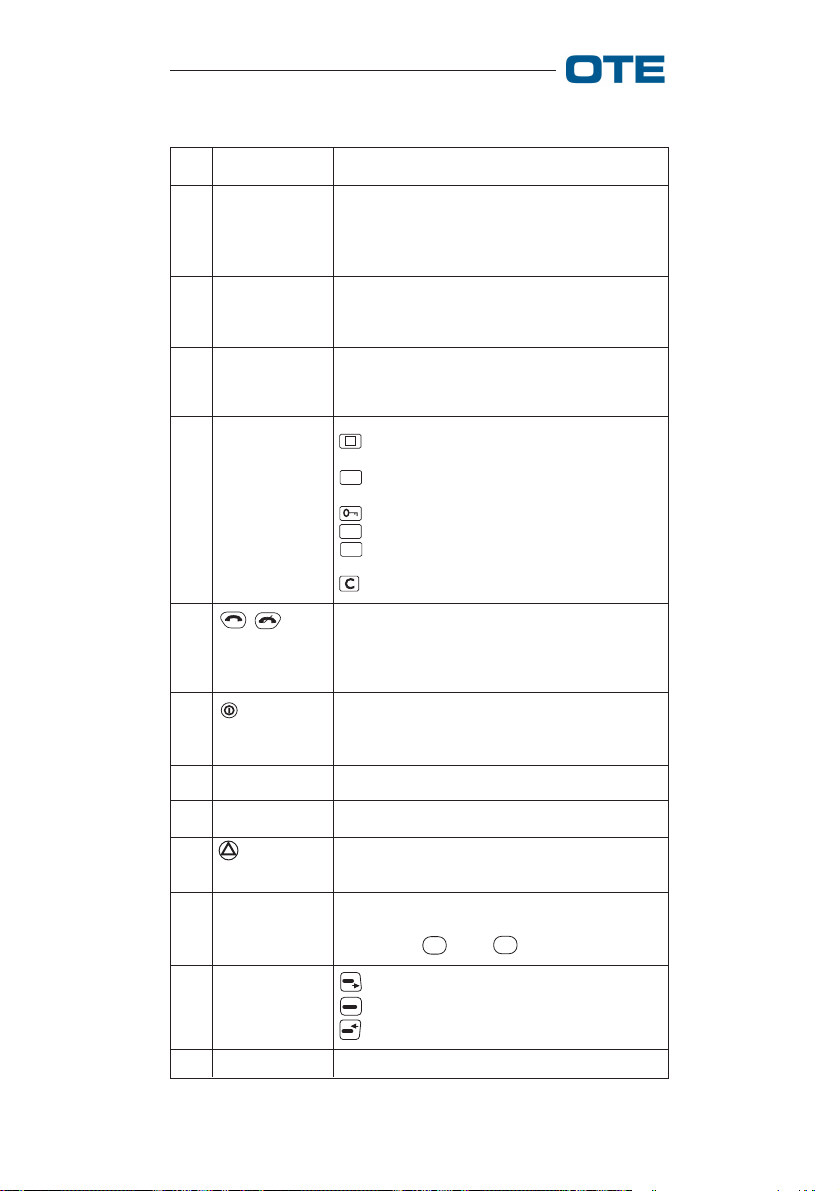
Tab. 1.1 - Controls and indicators
N° Indication Description
1
Group
Selector
2
LEDs
3
Volume
Control Knob
4
Function
Keys
5
16 settings selector: it enables selection of
any of the previously preset 16 groups.
The group call is activated pressing the
PTT.
Green led: lit while the radio is receiving.
Red led: lit while the radio is transmitting;
blinking in Tx Inhibit mode.
It lets user control the volume of the audio
output of the loudspeaker or of the earphone.
: Accessories (not active if just one type
of accessory is connected).
: Change Mode (Not active if only one
M
mode is set).
: Encryption.
: By PRP programmable key.
S
: Shows the sentence "Press PTT for
P
individual call" (only TMO).
: clear/escape key.
The on hook green key is used to accept/
make a call and if pressed in idle status
accesses the calls list. The off hook red key
is used to end a connection.
6
To switch the radio on/off. Fitted with a time
delay and a low profile to prevent accidental
activation.
7
8
9
Connector
Connector
Audio input signals.
RS232 serial line connector.
It lets the user make a call with emergency
priority to the group or user preset by PRP.
10
Alphanumeric
keyboard
Alphanumeric keypad for dialling numbers
and/or strings. It is made up of 12 keys (10
digits plus * and #).
11
12
Menu
navigation
keys
Display
: scrolling previous menu
: selection
: scrolling next menu
Backlit LCD display (160x80 pixel).
16 779-0217/03.04
VS 2001 Vehicular Radio Terminal
User’s Guide
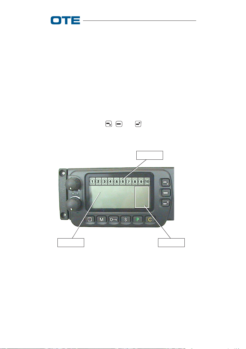
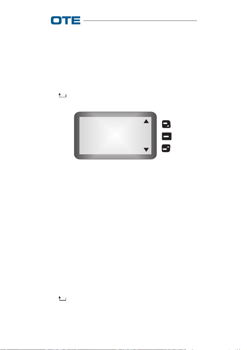
1.1 Display Layout
As shown in fig 1.2, the VS 2001 radio display is divided in
3 areas.
The first area is devoted to symbol representation (area 1)
whose functions are explained in tab. 1.2.
The second area is devoted to display/insert text information
(area 2).
Text information might be displayed either during menu
navigation or during the radio active/idle status.
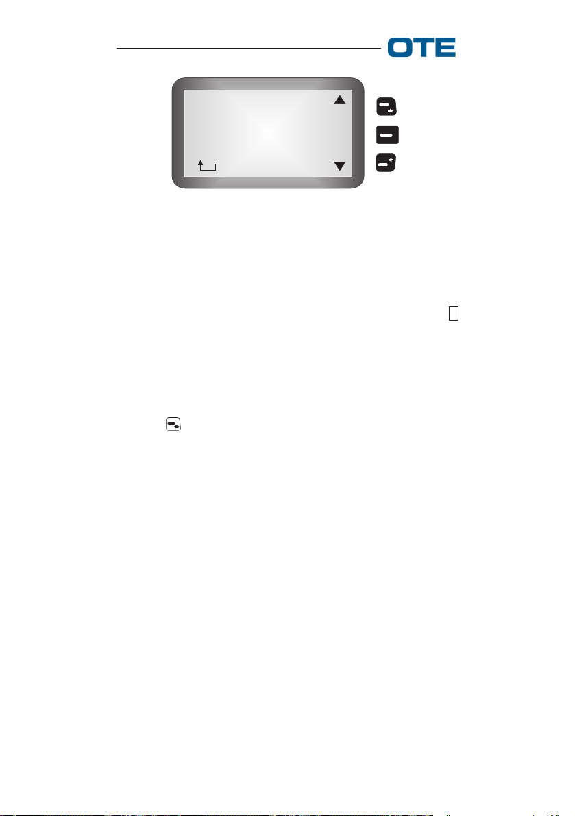
In the third area there are the symbols related to the pressing
of the navigation keys , and (area 3). In particular,
during function menu navigation, each of these keys find its
own match with the symbol directly beside it.
AREA 1
AREA 3AREA 2
Fig. 1.2 - VS 2001 Display
Tab 1.2 is set as follows:
• in the first column (symbol) all simbols displayed in the
first area (fig. 1.2) are listed;
• in the second column (position) references to the displayed simbol location are listed;
779-0217/03.04 17

VS 2001 Vehicular Radio Terminal
User’s Guide
• in the third column (meaning) the meaning of each corresponding symbol is explained.
Two symbols in the same position automatically exclude
each other: there can be only one at a time (see symbols
related to positions 2, 3, 5, 7).
Tab. 1.2 - Displayed symbols
Symbol Position Meaning
1
Signal level
2
Trunked Mode, searching network
(flashing)
2a
Direct Mode with DM-GATE device
presence detected
3
D
F
D
Direct Mode
3a
Fall-back Mode
3b
Direct Mode with DM-REP device
presence detected
4
Encryption enable
5
No read messages, full queue (flashing)
5a
Full queue, each message is read
+
S
18 779-0217/03.04
5+6
P
Data connection active
7
Earphone active
7a
Loudspeaker active
7b
Keypad DTMF OFF
8
Keypad locked
9
Headphone
10
Group scanning enable
VS 2001 Vehicular Radio Terminal
User’s Guide
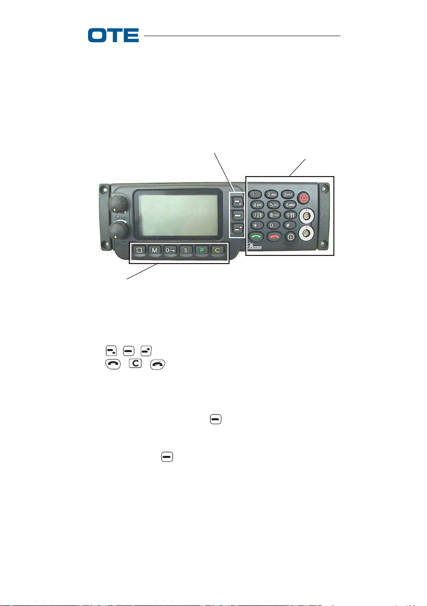
1.2 Buttons functionality
The general meaning and functions associated to each functional key of the keypad are here described (see fig. 1.3).
NAVIGATION KEYS
FUNCTION KEYS
ALPHANUMERICAL AND
FUNCTION KEYS
Fig. 1.3 - Front panel buttons
The , , keys are reserved for navigation menu, while
the , , keys have effect both during the menu
navigation and during all the other operations and procedures.
When the radio is in idle status the navigation menu is
activated by pressing the key when in area 3 (see fig. 1.2)
appears "MENU". It is also possible to activate the navigation menu when a call is active (only in TMO mode) by
pressing the key .
For what concerns all other keys these are normally devoted
to place alphanumeric characters (during message writing or
address dialling) into the display area 2 (fig. 1.2).
Moreover the alphanumeric keys of the keypad can operate
other functions during the navigation of particular menu
functions.
779-0217/03.04 19

VS 2001 Vehicular Radio Terminal
User’s Guide
2. VS 2001 use
In this section radio functions in each of the possible mode
are described.
VS 2001 equipment Operative Mode are:
• TMO (see section 2.1)
• DMO (see section 2.2)
The accessories using modality is described in Appendix A.
2.1 Radio switch on and main
menu in Trunked mode (TMO)
The radio is switched on with the On/Off button (fig. 1.1).
In wait status, press the * keys in sequence to lock the
keypad; the user is informed by a temporary "keypad locked"
message and the relative symbol appears on the display (tab.
1.2). When the keypad is locked, a dynamic help appears
when any key is pressed, which signals the proper sequence
to unlock it. The emergency key, the PTT, the key and
the knobs still work even when the keypad is locked.
To turn the radio off, keep the On/Off button pressed for a few
seconds, after which a message will appear on the display
stating that the radio data has been saved and the radio
switches off.
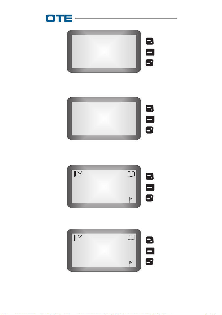
When the radio is turned on in Trunked mode, a welcome
screen appears, then the PIN entry request appears (fig. 2.1).
Once the PIN has been entered, the terminal searches for the
network and the word "Searching...." (see fig. 2.2) appears on
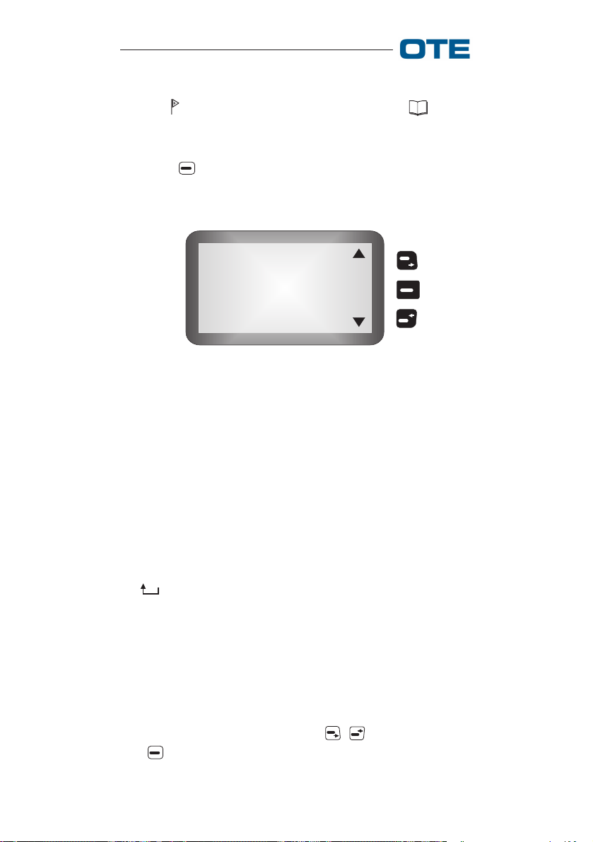
the display; if the terminal is under coverage, it visualizes:
• if a group is selected, the ID (or nickname if it exists) of
the group itself (see fig. 2.3a);
• if no group is selected, the terminal ID (see fig. 2.3b).
When instead the terminal is not under coverage, it emits a
beep and the symbol located in area 1 of the display
blinks.
20 779-0217/03.04
VS 2001 Vehicular Radio Terminal
User’s Guide
Insert
PIN:
Fig. 2.1 - PIN Insertion Request (TMO)
Searching....
Fig. 2.2 - Searching (TMO)
Group 209
Selected
M
E
N
U
Fig. 2.3a - Mode TMO
76
M
No GRP
Selected
E
N
U
Fig. 2.3b - Indication of service with no group selected
779-0217/03.04 21
VS 2001 Vehicular Radio Terminal
User’s Guide
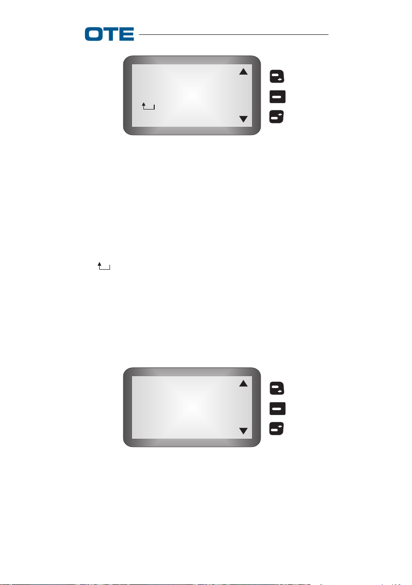
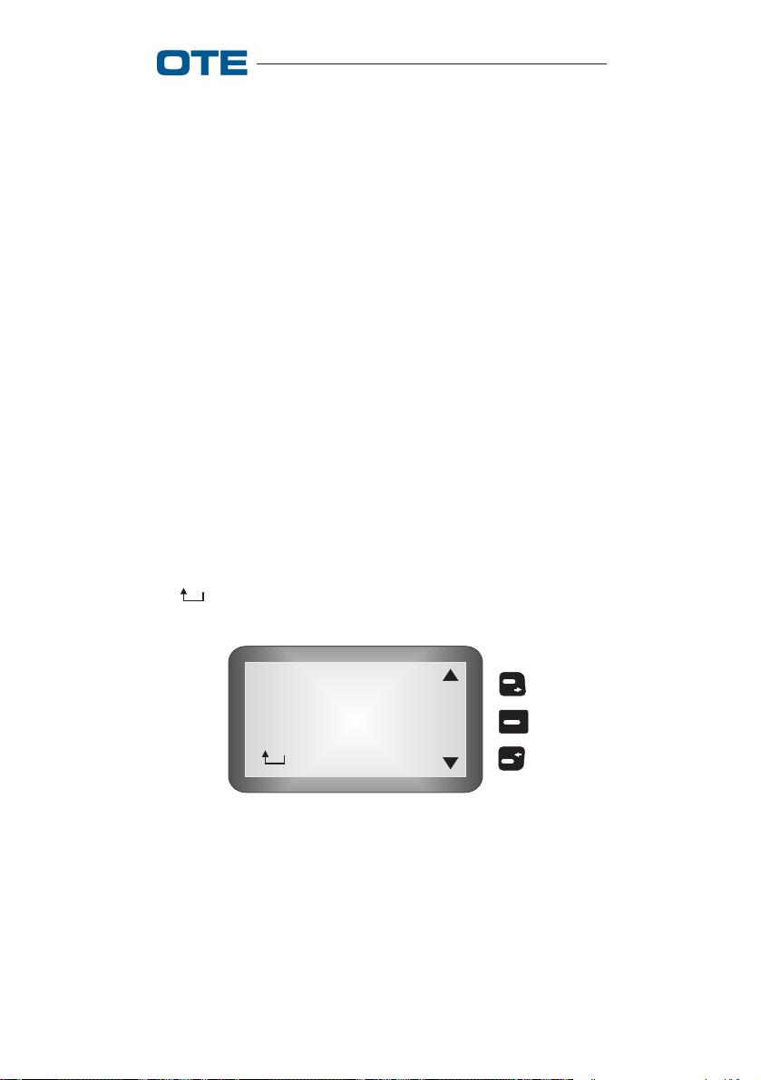
NOTE: In the case of coverage, in area 3 of the display the
symbols (send status, see section 2.1.1.4) and (phone
lists, see section 2.1.4) appear on the bottom and upper part
of the screen, respectively, the word MENU in the center.
Press the key associated with MENU (see figs. 2.3a and
2.3b) to enter the radio menu, as shown in fig. 2.4.
• Messages
• Change Mode
• Encryption
• Phone Lists
S
E
L
• Settings
Fig. 2.4 - Main Menu (TMO)
The main menu is composed of the following items:
• MESSAGES
• CHANGE MODE
• ENCRYPTION
• PHONE LISTS
• SETTINGS
• HELP
• : return to previous menu.
2.1.1 Messages
In Trunked mode, the access to the «Messages» menu allows
to read/send Status messages (preset) or User messages (user
defined).
To enter the «Messages» menu, select «Messages» from main
menu by using the navigation keys , and then press the
key .
22 779-0217/03.04
VS 2001 Vehicular Radio Terminal
User’s Guide
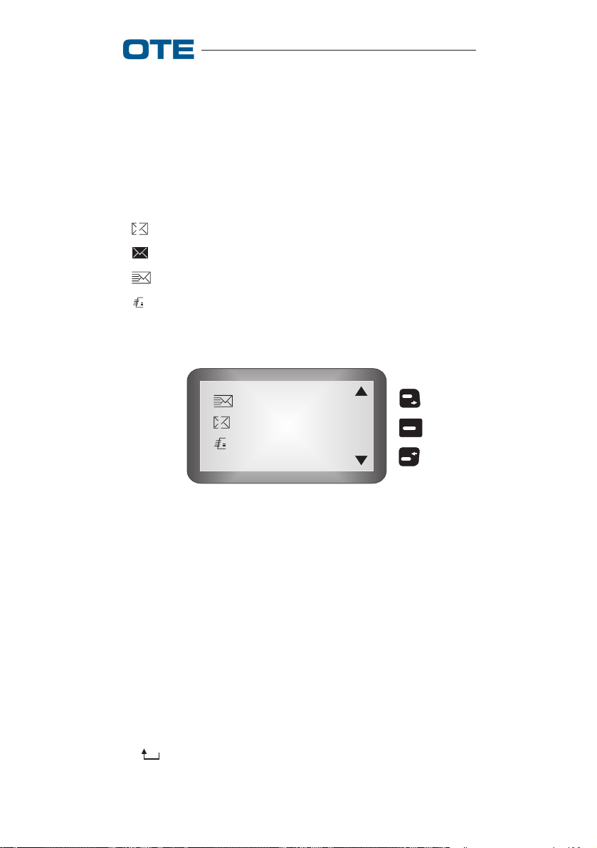
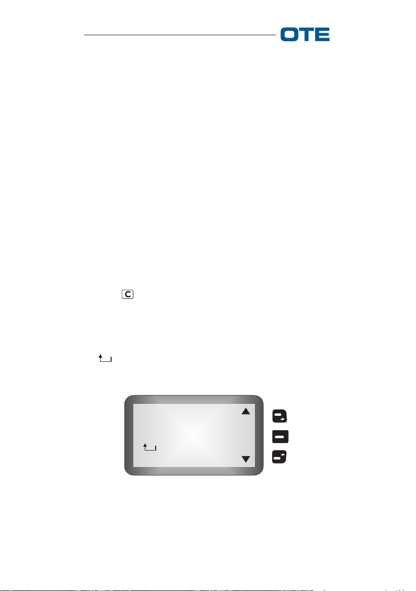
In fig 2.5 is illustrated the «Messages» menu in Trunked
mode.
• In Box
• Out Box
• Text Messages
• Send Status
S
E
L
•
Fig. 2.5 - «Messages» Menu (TMO)
From "Messages" menu, the following items can be selected:
• IN BOX
• OUT BOX
• TEXT MESSAGE
• SEND STATUS
• : Return to previous menu.
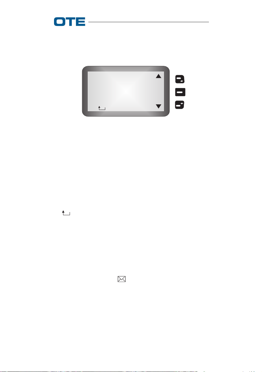
2.1.1.1 In Box
To read messages, select the function MESSAGES → IN BOX
from the main menu.
This menu allows the user to read the messages and statuses
received. The presence of unread messages in one of the two
queues is signaled by the symbol. If the menu is accessed
when the queue is empty, the timed message "EMPTY
QUEUE" appears, otherwise the list of received messages
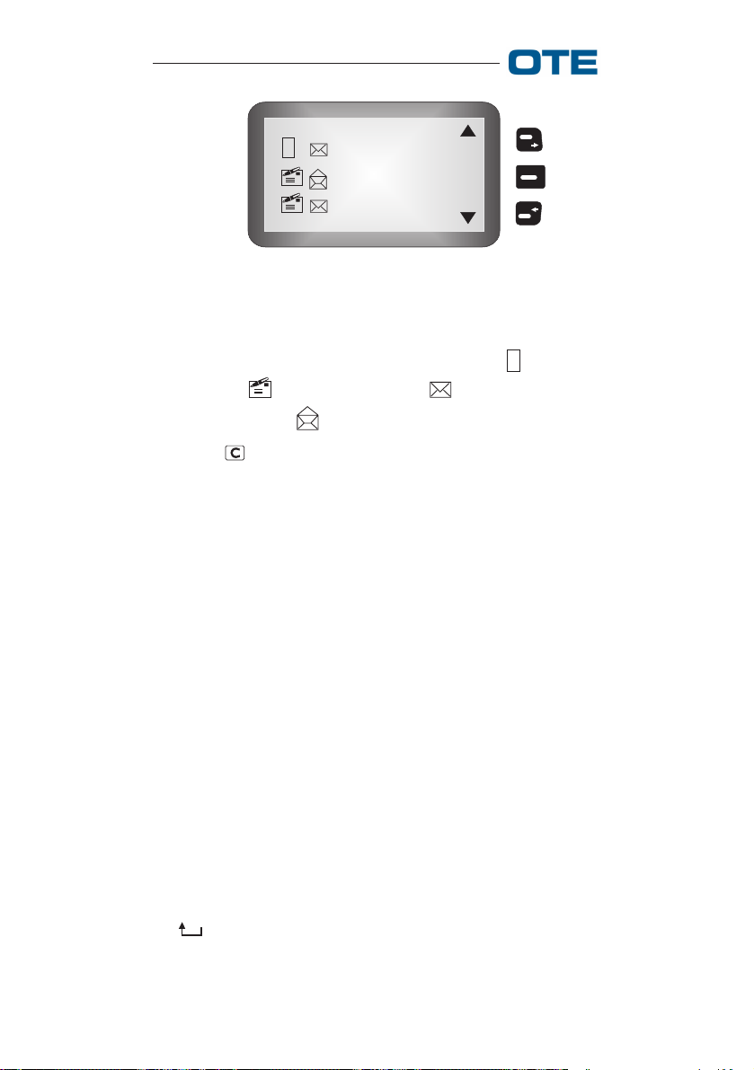
(type, status, nickname or ID) appears.
779-0217/03.04 23
VS 2001 Vehicular Radio Terminal
User’s Guide
S
Nickname
Nickname
Nickname
V
I
E
W
Fig. 2.6 - In Box Messages
The message type can be "STATUS MESSAGE" S or "TEXT
MESSAGE" ; the closed envelope indicates an unread
message and open indicates an already read message.
Press the key to return to the previous level and the keys
associated with the arrows to scroll through the messages in
circular fashion (forward and backward); press the key associated with "VIEW" to display the contents of the selected
message.
Status messages and text messages are displayed differently,
but for both of them the initials "OPT" appear on the right
part of the display; the key associated with "OPT" gives
access to the list of options.
The following options can be selected:
• DELETE: Deletes the current status or text message
after confirmation.
• REPLY: Gives access to the editing of a text message,
if a "TEXT MESSAGE" is being read, or to the status list,
if a "STATUS" message is being read, and then to dialling, presetting the sender's number.
• REPLY + HISTOR: This item is only visible if "TEXT
MESSAGES" is selected. It gives access to the editing of
a text message, presetting the received message, and then
to dialling, presetting the sender's number.
• : Return to previous menu.
24 779-0217/03.04
VS 2001 Vehicular Radio Terminal
User’s Guide
2.1.1.2 Out Box
To see the messages sent and the corresponding report received, select the MESSAGES → OUT BOX function from the
main menu.
If there are no messages, the words «EMPTY QUEUE» appear, otherwise the list of sent messages appears (status, nickname) (fig. 2.7):
• not received by addressee
• full queue
• sent and received by addressee
??
•
message not yet received by addressee (awaiting report)
Nickname
Nickname
??
Nickname
V
I
E
W
Fig. 2.7 - Out Box
The key associated with "VIEW" displays the contents of the
selected message (see fig. 2.8):
The key associated with "OPT" gives access to the list of
options. The following options can be selected:
• DELETE: Deletes the current text message after confirmation.
• RESEND: Allows sending the same message again, presetting the addressee's number:
• : Return to previous menu.
779-0217/03.04 25

VS 2001 Vehicular Radio Terminal
User’s Guide
Received
Sent to ...................
Message text
O
P
T
Fig. 2.8 - Read Out Box
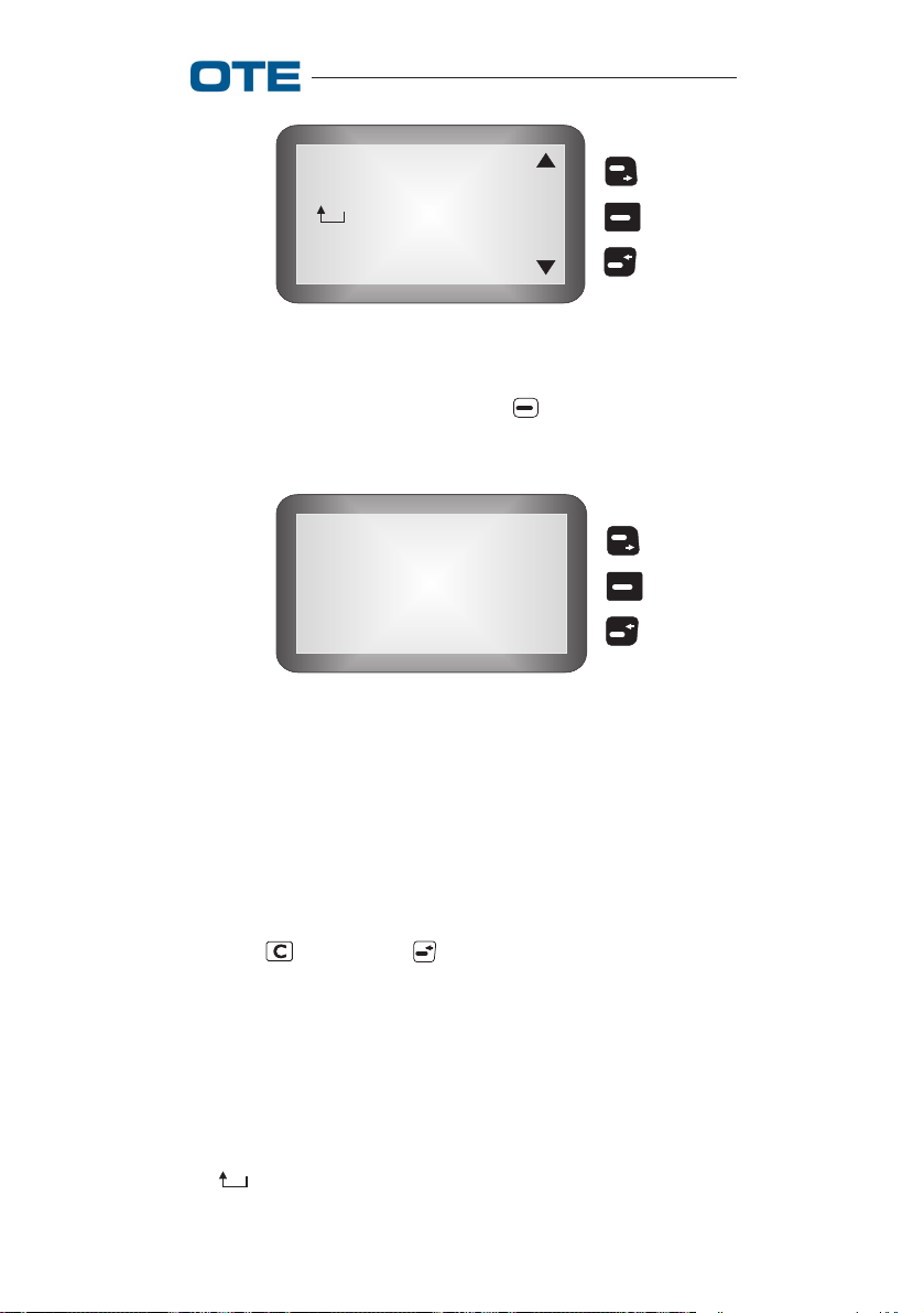
2.1.1.3 Text Messages
To create, modify and send text messages (SDS), select the
MESSAGES → TEXT MESSAGE function from the main
menu.
The screen shown in fig. 2.9 will appear.
< New>
First Memo . . . . . .
Second Memo . . . .
S
E
L
Fig. 2.9 - Text Messages
NOTE: When one of the "Memos" is selected, "SEL" turns
into "VIEW".
• When " <NEW>" is selected, if the queue is not full,
the composition mode is activated (fig. 2.10). If the queue
is full, the message shown in fig. 2.11 appears.
26 779-0217/03.04

VS 2001 Vehicular Radio Terminal
User’s Guide
-
O
P
T
✎ A B C
Fig. 2.10 - Text Message Composition
BACK
FULL QUEUE
Impossible to save!
NEXT
Fig. 2.11 - Text Message Queue Full
NOTE: "Upper case" or "lower case" editing is indicated by
the "ABC" and "abc" strings, respectively, visualized on the
display; using the * key, it is possible to select whether to
use the key in upper or lower case.
The message is written using the alphanumeric keypad. To
scroll all of the characters associated with the same key, press
it consecutively. To write two or more consecutive characters
associated with the same key, wait a couple of seconds (approx. 2 sec.) between one entry and the next.
Use the and navigation keys to scroll through the
already written characters.
Press the key to delete the last character entered or any
character selected with the navigation keys. On the contrary,
prolonged pressing of the key deletes the entire message;
if nothing has been typed, we go back to the upper menu
level.
779-0217/03.04 27

VS 2001 Vehicular Radio Terminal
User’s Guide
All of the characters associated with the keys are listed in tab.
2.1.
Once you've edited the message, from the fig. 2.10 screen,
pressing the key, the fig. 2.12 screen appears.
Tab. 2.1 - Characters Associated with the Keys
0 blank 0
1 1¼½¾¢ §¨©ª«¬ ®¯°±²³´¶·¸¹º»
2
Uppercase:
ABC2@ДЖЕАБВГЗ
Lowercase:
abc2@джеабвгз
3
Uppercase:
DEF3ИЙКЛР
Lowercase:
def3ийклр
4
Uppercase:
GHI4ÌÍÎÏ
Lowercase:
ghi4ìíîï
5
Uppercase:
JKL5 £
Lowercase:
jkl5£
6
Uppercase:
MNO6СТУФХЦШ
Lowercase:
mno6стуфхцшµ
7
Uppercase:
PQRS7$
Lowercase:
pqrs7ß$
8
Uppercase:
TUV8ÙÚÛÜ
Lowercase:
tuv8ùúûü
9
Uppercase:
WXYZ9×ÝÞ
Lowercase:
wxyz9ýÿþ
* *.,?!"-()@/:_;+&%=<>£$¥
¤[]{}\~^¡¿§#|'`
#
Uppercase-Lowercase selection
Send
Save
Save & Send
S
E
L
Fig. 2.12 - Text Message Option
28 779-0217/03.04

VS 2001 Vehicular Radio Terminal
User’s Guide
• SEND
Once the message has been written, press the key to
enter the receiving user's address (fig. 2.13).
If the GSSI of a particular group is typed, or after having
selected a group from among those that appear when the
key is pressed, the message will be sent to all of the
radios belonging to that group. Vice versa, when the ISSI
of a radio is typed directly, or when searching for it in the
phone book using the key, the message will be sent
only to the radio to which the typed in ISSI corresponds.
After having selected or composed the address, the word
"SEND" appears on the display; press the key to
confirm the send.
It is wortwhile noting that the message is sent, but it is
not saved.
• SAVE
In this case, proceed as for "SEND", writing the message,
but pressing the key, it is possible to save instead of
send the message.
• SAVE & SEND
In this case it is possible to save the message before
sending it.
• : return to previous menu.
Address:
Fig. 2.13 - Composition of Receiver's Address
779-0217/03.04 29

VS 2001 Vehicular Radio Terminal
User’s Guide
2.1.1.4 Send Status
Status messages are 16 bit numbers associated with some
descriptive strings of 24 characters max, configured from
PRP. When this item is selected, the screen (fig. 2.14) relative
to the messages that can be sent appears.
EMERGENCY
URGENT CALL....
O
K
CALL BACK
Fig. 2.14 - Status Messages
Scrolling through the menu with the and keys, the
following options can be selected:
• EMERGENCY
• URGENT CALL BACK
• CALL BACK
• User defined Ø ÷ 61
• : return to previous menu.
The key associated with "OK" or the " " key select the
message; if the message is longer than 12 characters, it is
displayed in detail, otherwise we move on to enter the addressee. At this point, with "OK", the user can enter the
addressee of the message and send it with the " " key, the
"G" key, PTT or "SEND" (activated after the first character is
entered) (see fig. 2.15).
30 779-0217/03.04

VS 2001 Vehicular Radio Terminal
User’s Guide
Address:
S
E
N
D
Fig. 2.15 - Enter Message Addressee (TMO)
The key allows the user to access the phone lists to
automatically select the addressee of the message.
It is possible to access this "Send Status" menu also from the
idle status screen, pressing the key corresponding to the
symbol.
2.1.1.5 Return to Previous Menu
This function, represented in the menu by the " " symbol,
indicates the completion of the possible choices and allows,
if selected, returning to the upper menu level. We get the
same function by pressing the key from the menu.
2.1.2 Change Mode
To access mode, select the CHANGE MODE function from
the main menu.
Now, the following question is shown: "change in Direct?",
you can answer "YES" or "NO" by the corresponding keys.
NOTE: It is possible to access this menu even by pressing
the M key.
NOTE: It is possible to enable/disable the operating modes from PRP; if a radio contains only one operating mode,
this menu is not visible.
779-0217/03.04 31
VS 2001 Vehicular Radio Terminal
User’s Guide
2.1.3 Encryption
This menu allows the user to configure the services relative
to E2E Encryption management. This menu is not visible if
the radio does not support this function.
To access the encryption function, select → ENCRYPTION
from the main menu.
NOTE: It is possible to access this menu even by pressing
the key.
The following items can be selected (fig. 2.16):
• E2EE STATUS
• E2EE KEY
• : return to previous menu (see section 2.1.1.5).
E2EE Status
E2EE Key
S
E
L
Fig. 2.16 - Encryption Menu
2.1.3.1 E2EE Status
This function allows the user to modify the call default mode.
The Enable/Disable options are available (see figs. 2.17 and
2.18).
If the encryption system is enabled, the key symbol appears.
Use the key associated with "YES" to confirm the modification, which will be maintained even after the radio is turned
off.
32 779-0217/03.04
VS 2001 Vehicular Radio Terminal
User’s Guide
Enable
YES
Encryption?
NO
Fig. 2.17 - Encryption Enabled
Disable
YES
Encryption?
NO
Fig. 2.18 - Encryption Disabled
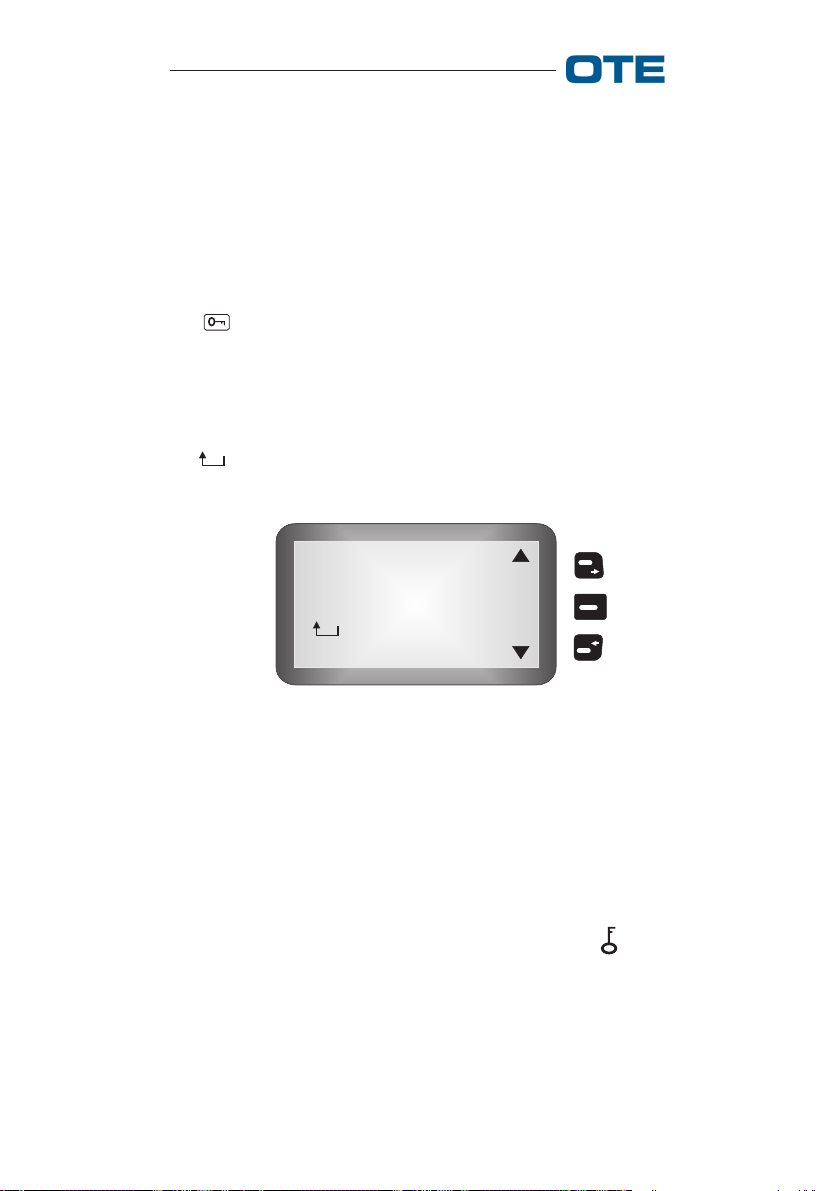
2.1.3.2 E2EE Key
This function allows the user to modify the default crypto
key; the menu is not visible if only one key is configured
(see fig. 2.19).
Crypto Key1
Crypto Key2
O
K
Crypto Key3
Fig. 2.19 - Encryption Keys
After selection of an encryption key with the key, associated with "OK", the selection is confirmed and the new
value will be maintained even after the radio is turned off.
779-0217/03.04 33
VS 2001 Vehicular Radio Terminal
User’s Guide
2.1.4 Phone lists
This menu allows the user to call the stored users directly and
to enter new names.
To access the phone lists, select the → PHONE LISTS function from the main menu.
The following items can be selected (fig. 2.20):
• PHONE BOOK: new users, the directory and the possibi-
lity of MODIFYING and DELETING
• HOME TETRA: TETRA users entered from PRP
• NON TETRA: list of addresses of subscribers belon-
ging to NON-TETRA networks
• : return to previous menu (see section
2.1.1.5).
NOTE: The "Home Tetra" and "Non Tetra" lists are configured from PRP.
Phone Book
Home Tetra
Non Tetra
S
E
L
Fig. 2.20 - "Phone Lists" Menu
2.1.5 Settings
This menu allows the user to configure some equipment
functions.
To access the settings, select the → SETTINGS function from
the main menu.
The following items can be selected (fig. 2.21):
34 779-0217/03.04
VS 2001 Vehicular Radio Terminal
User’s Guide
• GROUP MNG
• CALLS
• DELIVERY OPT.
• TX INHIBIT
• PREFERENCES
• AUX. MICROP.
• FULL DUPLEX
• : return to previous menu (see section 2.1.1.5).
Group Mng
Calls
Delivery opt.
Tx Inhibit
S
E
L
Preferences
Aux. Microp.
Fig. 2.21 - "Settings" Menu
2.1.5.1 Group MNG
This menu allows configuring and activating the services
relative to group management.
To access the group management menu, select the → SET-
TINGS→ GROUP MNG function from the main menu.
The following items can be selected (fig. 2.22):
• GROUP SCAN.
• WPS SELECT.
• WPS UPDATE
• WPS RECONF.
• : return to previous menu (see section 2.1.1.5).
779-0217/03.04 35
VS 2001 Vehicular Radio Terminal
User’s Guide
Group Scan
WPS Select
WPS Update
WPS Reconf.
S
E
L
Fig. 2.22 - "Group MNG" Menu
2.1.5.1.1 Group Scan
This function allows the user to activate/disactivate the
group scanning function; when scanning is active, the
symbol is on. Modification of the current status is requested
when entering the menu.
If scanning is not active, «Scanning On?» appears on the
display; instead, if scanning is active, «Scanning Off?» appears on the display.
Use the key, associated with "YES", to confirm the modification, which will be maintained even after the radio is
turned off.
S
NOTE: From PRP it is possible to configure the default
value when the radio is turned on and the parameters associated with functionality.
In TMO, passage between "Scanning On" and "Scanning Off"
leads to the ending of an active group call if it is not to the
group selected.
2.1.5.1.2 WPS Select
This function allows the user to select a new WPS.
When the menu is accessed, the names (12 characters max)
of the WPSs configured from PRP are displayed; the first item
corresponds to the current setting. Following a new selection,
the key associated with «OK» requests, after confirmation,
activation of the selected WPS.
36 779-0217/03.04

VS 2001 Vehicular Radio Terminal
User’s Guide
After a wait message, an informative message appears both in
the case of success and in the case of failure of at least one
request relative to a group belonging to the WPS.
NOTE:
• The names of the WPSs have a maximum length of 12
characters; if the name does not fit in the display, it is
abbreviated with the «...» character.
• The key allows exiting the menu without changing
the current active WPS. In the case of modification, the
new WPS will be maintained even after the radio is
turned off.
• Changing WPS during a group call leads to its ending.
2.1.5.1.3 WPS Update
This function allows the user, if enabled from PRP, to modify
some characteristics of the current WPS and of the contained
groups.
The following items can be selected (see fig. 2.23):
• WPS data
• Group data
• : return to previous menu (see section 2.1.1.5).
WPS Data
Group Data
S
E
L
Fig. 2.23 - WPS Update
779-0217/03.04 37
VS 2001 Vehicular Radio Terminal
User’s Guide
NOTE: There are some parameters, configurable from
PRP, that indicate whether or not the user is enabled to
modify the WPSs; if it should happen that a radio has all
functions disabled, the "WPS Update" menu is not visible.
In TMO, modification of the WPS leads to the ending of an
active group call.
WPS Data: This function allows the user, if enabled from
PRP, to modify some characteristics of the current WPS.
Entering the menu, the modifiable parameters are proposed in
sequence.
WPS Name:
NAME
O
K
✎ A B C
Fig. 2.24 - WPS Name Modification
In this case, the name of the WPS is proposed. It is possible,
using the arrows, to move within the name and use the alphanumeric keypad to edit the new name. The key associated
with "OK" confirms the name modification and, only if the
DMO protocol is configured, we move to the next modification parameter, "radio channel" (see fig. 2.25).
Use the and keys to scroll through the channels and
relative frequencies in circular fashion. The key associa-
ted with "OK" confirms the selection.
38 779-0217/03.04

VS 2001 Vehicular Radio Terminal
User’s Guide
Radio Channel 02
O
390.000
K
Fig. 2.25 - WPS Radio Channel Modification
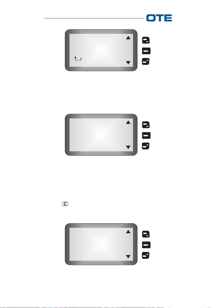
Group Data: This function allows the user, if enabled, to
modify some characteristics of the groups. Entering the
menu, it is possible to display the list of groups contained in
the current WPS and request its modification, for ex.:
Group 209
Selected
SSI 209
High priority
Channel 02
Valid
M
O
D
Fig. 2.26 - "Group Data" Menu
The following information is displayed:
• group name;
• status, the word "Selected" appears only if the group is the
one currently selected;
• Group SSI;
• Group Priority;
• if the DMO protocol is configured, the channel associated
with the group;
779-0217/03.04 39
VS 2001 Vehicular Radio Terminal
User’s Guide
• group status, i.e.:
"valid" → Group attached
"not valid" → Group not attached
The keys associated with the arrows scroll through the groups
in circular fashion (forward and backward); the key associated with "MOD" requests modification of the current group.
At this point, the first modifiable parameter is proposed, if
enabled from PRP, for example, the group name (fig. 2.27).
GROUP NAME:
Group 209
O
K
✎ A B C
Fig. 2.27 - "Group Name" Modification
Use the arrows to move within the name and use the alphanumeric keypad to edit the new name. The key associated
with "OK" confirms the name modification, then we move on
to the next modification parameters, if enabled from PRP.
NOTE: If the possibility of modifying any parameter is not
given from PRP, then the "Group Data" menu is not visible.
2.1.5.1.4 WPS Reconf.
This function allows the user, if enabled from PRP, to modify
the composition of the current WPS.
The following items can be selected (fig. 2.28):
• ACTIVE WPS
• EXTRA WPS
• : return to previous menu (see section 2.1.1.5).
40 779-0217/03.04
VS 2001 Vehicular Radio Terminal
User’s Guide
Active WPS
Extra WPS
S
E
L
Fig. 2.28 - Reconfigure WPS
With "Active WPS ", the user can delete or add groups in the
current WPS. The following items can be selected:
• ADD
• DELETE
• : return to previous menu (see section 2.1.1.5).
ADD: This function allows the user to add groups in the
current WPS. Entering the menu, the list of groups present in
the "Group List" but not belonging to the current WPS is
displayed, for ex. fig. 2.29.
Group 209
SSI 209
High priority
A
D
D
Channel 02
Fig. 2.29 - "Add" Menu
NOTE: If there are no groups to be added to the list, the
temporary message "No group to add" appears.
779-0217/03.04 41

VS 2001 Vehicular Radio Terminal
User’s Guide
The following information is displayed:
• group name;
• group SSI ;
• group priority;
• if the DMO protocol is configured, the channel associated
with the group.
The keys associated with the arrows scroll through the groups
in circular fashion (forward and backward), the key associated with "ADD" adds, after confirmation (fig. 2.30), the selected group to the current WPS (if there are no free positions
in the current WPS, a temporary warning message appears).
YES
Add
New Group?
NO
Fig. 2.30 - Confirm "Add"
DELETE: This function allows the user to delete groups
from the current WPS. Entering the menu, if the active WPS
is empty, a temporary message appears, otherwise the list of
groups present in the current WPS is visualized.
The following information is displayed:
Group 209
Selected
SSI 209
High priority
Radio channel 02
Valid
D
E
L
Fig. 2.31 - "Delete" Menu
42 779-0217/03.04

VS 2001 Vehicular Radio Terminal
User’s Guide
• group name;
• group SSI ;
• group priority;
• if the DMO protocol is configured, the channel associated
with the group;
• the group status, i.e.:
"valid" → Group attached
"not valid" → Group not attached
The keys associated with the arrows scroll through the groups
in circular fashion (forward and backward), the key associated with "DEL" deletes, after confirmation, the selected group
from the current WPS.
YES
Delete
Group?
NO
Fig. 2.32 - Confirm Delete
NOTE: Removal of the selected group is not allowed
("Wrong operation") when the group is selected.
Furthermore, if there is a call underway on the group that
we wish to delete, the call is ended.
With "Extra WPS", the user has the possibility of moving the
assigned groups through DGNA (dynamic groups created by
the NMS) into the current WPS.
Entering the menu, if the Extra WPS is empty, the message
"Extra WPS empty" message appears, otherwise the list of
groups present in the Extra WPS is visualized (see fig. 2.33).
The following information is displayed:
779-0217/03.04 43

VS 2001 Vehicular Radio Terminal
User’s Guide
Group 209
SSI 209
High priority
Channel 02
M
O
V
E
Valid
Fig. 2.33 - Extra WPS
• group name;
• group SSI;
• group priority;
• if the DMO protocol is configured, the channel associated
with the group;
• the group status, i.e.:
"valid" → Group attached
"not valid" → Group not attached
The keys associated with the arrows scroll through the groups
in circular fashion (forward and backward), the key asso-
ciated with "MOVE" requests, after confirmation, moving the
group into the current WPS (if there are no free positions in
the current WPS, a temporary warning message appears).
2.1.5.2 Calls
This menu allows the user to configure the services associated with call management.
To access the call, select the → SETTINGS→ CALLS function from the main menu.
The following items can be selected (fig. 2.34):
• LATE ENTRY
• GROUP CALL
• DIAL MODE
• GATEWAY
• : return to previous menu (see section 2.1.1.5).
44 779-0217/03.04

VS 2001 Vehicular Radio Terminal
User’s Guide
Late Entry
Group Call
Dial Mode
Gateway
S
E
L
Fig. 2.34 - "Calls" Menu
2.1.5.2.1 Late Entry
This function, if set from PRP, allows the user to enable/
disable Late Entry in group calls.
The enabled "Late Entry" option allows the user who enters
a group to participate in a call (if it is a group call) that is
already underway on the same. If "Late Entry" is not enabled,
the user who enters a group after the establishment of a call
to that group, cannot participate.
Entering the menu, modification of the current status is requested, i.e. if "Late Entry" is disabled, the request to enable
it is made, and vice versa. Use the key associated with "YES"
to confirm the modification, which will be maintained even
after the radio is turned off.
2.1.5.2.2 Group Call
This function allows the user to modify the default group call
type.
Entering the menu, the current setting is shown. Use the
and keys to select the desired mode, and the key,
associated with "OK", to confirm the selection, which will be
maintained even after the radio is turned off.
The following items can be selected (fig. 2.35):
• GROUP UNACKNOWLEDGE: the call enters directly.
• GROUP ACKNOWLEDGE: the call enters if and only if
there is a sufficient number of users connected; depending on the release, the network may not support this
feature.
• GROUP BROADCAST: the call enters directly, but the
receiver can only listen.
• : return to previous menu (see section 2.1.1.5).
779-0217/03.04 45

VS 2001 Vehicular Radio Terminal
User’s Guide
Group Unack
Group Ack
Group Broad.
O
K
Fig. 2.35 - Group Call
NOTE: If «GROUP BROADCAST» is selected, the receiver
will not be able to speak even if he presses the PTT button,
and «NO REPLY» will appear on his terminal.
2.1.5.2.3 Dial Mode
This function allows the user to modify the default dialling
mode configured from PRP.
The following items can be selected (fig. 2.36):
• HOME TETRA: a complete SSI (Short Subscriber Identity) is to be specified. An SSI address consists of 7 or 8
digits, depending on the configuration by PRP. If the
number of digits entered is less than the SSI length, the
specified portion is regarded as the least significant digits
and the address is completed with 0s (i.e. SSI length=7
and 123 is entered then 0000123 is the called address).
• SHORT HOME TETRA: either a partial or a complete SSI
can be specified. If the number of digits entered is less
than the SSI length, the specified portion is regarded as
the least significant digits. In this case the address is
completed on the basis of a predefined SSI locally stored
on the terminal.
• SHORT NUMBER: the SNA address space is composed
by only 255 codes in the range 1÷255; when using the
SNA dialling algorithm the user has to insert from one up
to three digits. If the most significant digits of the SNA
are 0s these may be omitted by the user during dialling
(e.g.: the SNA 004 may be simply inserted as 4).
46 779-0217/03.04

VS 2001 Vehicular Radio Terminal
User’s Guide
• EXT.TETRA: the address to be specified is a complete
TSI (Tetra Subscriber Identity). It is composed by three
main parts: MCC (Mobile Country Code, 3 digits), MNC
(Mobile Network Code 4 or 5 digits configured by PRP)
and the SSI.
The TSI is comprehensive of a gateway identification in
order to issue the call outside the network (the gateway
id. is implicit in the TSI and depends on the network
numbering scheme).
• : return to previous menu (see section 2.1.1.5).
Home Tetra
Short Home
Short Number
Ext. TETRA
O
K
Fig. 2.36 - Dial Mode
Entering the menu, the current setting is shown at the top of
the list. After selection using the key, associated with
"OK", the default dialling mode is modified and the selection
is maintained even after the radio is turned off.
2.1.5.2.4 Gateway
This function allows the user to display the list of gateways,
towards networks outside the TETRA network, configured in
the equipment, and to select the default gateway. The gateways can be of three types:
• PSTN
• PABX
• ISDN
Entering the menu, the type, name (12 characters max. ) and
ID of the default gateway are visualized. After selection using
779-0217/03.04 47

VS 2001 Vehicular Radio Terminal
User’s Guide
the key, the default gateway is modified and the choice
is maintained even after the terminal is turned off.
NOTE: If only one gateway is configured in the equipment, the scrolling arrows are disactivated and only the
current gateway can be displayed.
2.1.5.3 Delivery Opt.
To access the report, select the → SETTINGS→ DELIVERY
OPT. function from the main menu.
The following items can be selected:
• Received
• No Report
• : return to previous menu (see section 2.1.1.5).
This function allows the user to configure the type of report
requested after a message is sent.
2.1.5.4 Tx Inhibit
To access this menu, select the SETTINGS → TX INHIBIT
function from the main menu. This function allows the user
to inhibit the transmission, in such a case the user will be
able to receive calls or SDS without delivery options.
By selecting "Tx Inhibit" the screen in fig. 2.37 is shown.
YES
Enable
Tx Inhibit?
NO
Fig. 2.37 - Tx Inhibit
48 779-0217/03.04

VS 2001 Vehicular Radio Terminal
User’s Guide
By pressing the key corresponding to "YES" you modify
the terminal status.
If this function is activated, pressing PTT or trying to make
a call, you'll have the screen shown in fig. 2.38.
Tx Inhibit
On
Fig. 2.38 - Tx Inhibit ON
Furthermore when transmission is inhibited the red led (see
fig. 1.1) is blinking.
Once this function is enabled you can disactivate it, by
acting in a similar way the user will be asked: "Disable Tx
Inhibit?", choosing "YES" will turn the terminal in the normal mode.
2.1.5.5 Preferences
This menu makes it possible to configure some equipment
parameters.
To access the preferences, select the → SETTINGS→ PREFERENCES function from the main menu.
The following items can be selected (see fig. 2.39):
• PIN
• LANGUAGE
• SOUNDS
• BACKLIGHT
• LCD CONTRAST
• : return to previous menu (see section 2.1.1.5).
779-0217/03.04 49

VS 2001 Vehicular Radio Terminal
User’s Guide
Pin
Language
Sounds
Backlight
S
E
L
LCD Contrast
Fig. 2.39 - "Preferences" Menu
2.1.5.5.1 Pin
This function allows the user to enable/disable Pin entry
when the terminal is turned on and, if enabled, to modify it.
The equipment can be configured from PRP in three different
ways:
• the equipment does not request the PIN when it is turned
on, the PIN menu is not visible;
• the equipment requests the PIN when it is turned on, the
ENABLE/DISABLE menu is not visible;
• all PIN menu items are visible.
NOTE: No keypad DTMF tone is emitted while the PIN
is being entered.
In general, the user can find himself in two different conditions:
• Pin disabled
• Pin enabled
The menu shows different functions depending on the Pin
status (Enabled/Disabled).
Pin Disab.: In this case, it is possible to access only the
"Enab./Disab." item from the menu (see fig. 2.40).
50 779-0217/03.04
VS 2001 Vehicular Radio Terminal
User’s Guide
Enab./Disab.
S
E
L
Fig. 2.40 - "Enab./Disab." Menu
Selecting "Enab./Disab." using the key associated with
SEL, the screen shown in fig. 2.41 appears.
YES
Enable
PIN?
NO
Fig. 2.41 - "Enable PIN?" Menu
After confirmation using the key associated with "YES", you
are requested to enter the new PIN. After confirmation and the
check to see if the PIN entry was successful, a message informs the user that the PIN status has been modified and the
equipment is reinitialized, otherwise the entry sequence is
reproposed.
Use the key or the key associated with "NO" to go
back to the upper menu level without modifying the PIN
status.
Pin Enab.: In this case, three items are available from the
menu (fig. 2.42):
• Change
• Enabled/Disabled
• : return to previous menu (see section 2.1.1.5).
779-0217/03.04 51
VS 2001 Vehicular Radio Terminal
User’s Guide
Change
Enabled/Disabled
S
E
L
Fig. 2.42 - "Pin" Menu
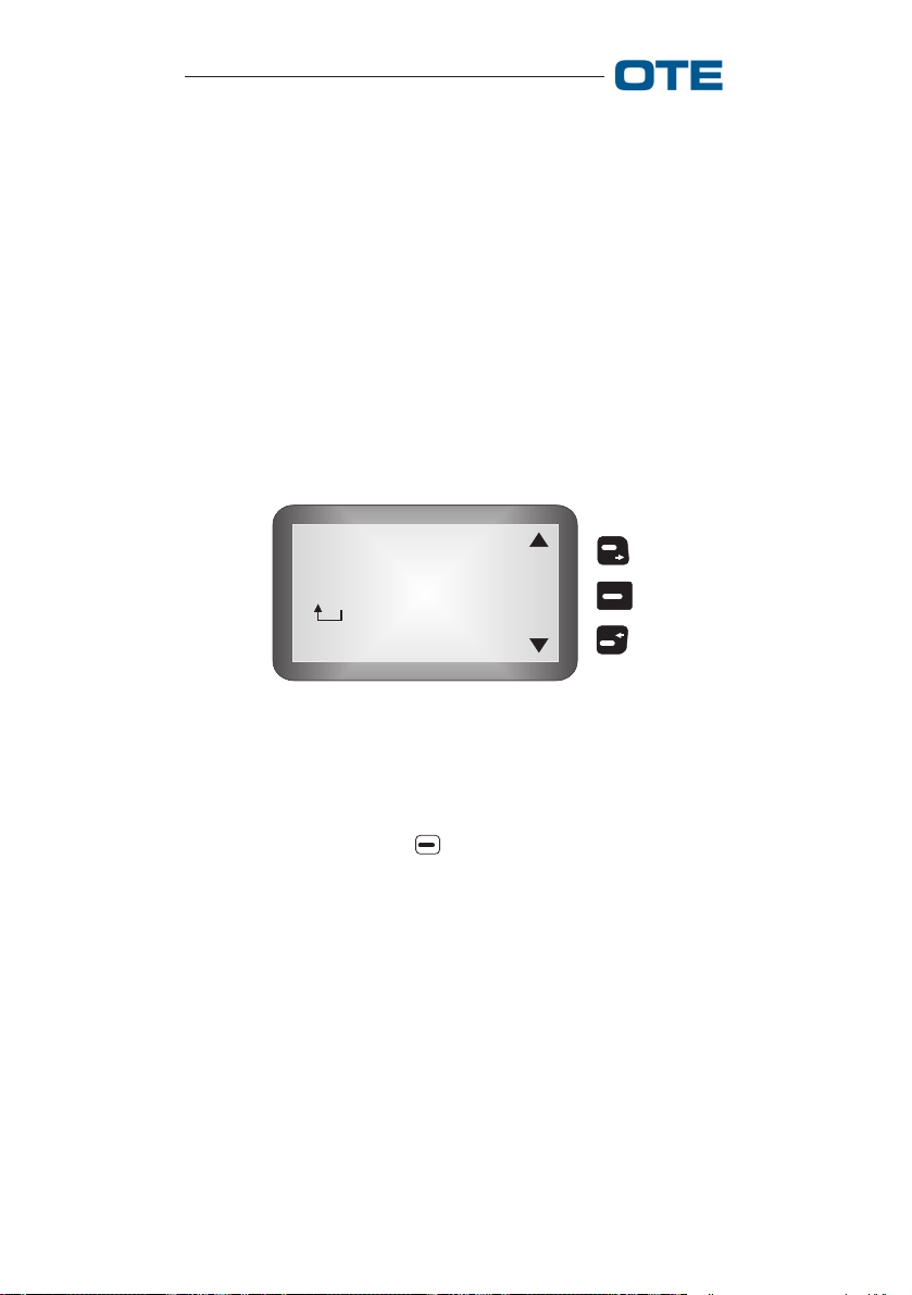
When "Change" is selected, you are requested to enter the
current PIN (see fig. 2.43).
Insert
PIN:
Fig. 2.43 - "Change" Menu
The user can type the PIN using the keypad; while the PIN
is being typed, some asterisks appear on the display, as
shown in fig. 2.44.
Use the key to delete the input and go back to the upper
level without changing the PIN.
* * * * * * * *
O
K
Fig. 2.44 - PIN Insertion
52 779-0217/03.04

VS 2001 Vehicular Radio Terminal
User’s Guide
Once PIN entry is complete, use the key associated with
"OK" to confirm the input; verification of the PIN then begins; if it is incorrect, the user is informed with an "Incorrect
PIN !" message, otherwise he is requested to enter the new
PIN.
Similarly to what is described above, the user must enter the
new PIN and confirm with the key.
If the PIN modification operation is unsuccessful, the entire
modification sequence is reproposed, otherwise, the user is
informed with a "PIN modified!" confirmation message.
Select "Enab./Disab." to modify the pin status from enabled
to disabled (see fig. 2.45).
YES
Disable
PIN?
NO
Fig. 2.45 - "Enab./Disab." Menu in the case of PIN
enabled
Use the key or the key, associated with "NO", to go
back to the upper menu level without modifying the PIN
status.
When the key, associated with "YES", is pressed, you are
asked to enter the current PIN (fig. 2.43).
After entering the PIN, the user can confirm it with the key
associated with "OK"; PIN verification thus begins.
If the PIN entered is incorrect, the user is informed with the
"Incorrect PIN!" message, otherwise the modification is confirmed with the "PIN Status Modified!" message and the
equipment is reinitialized.
779-0217/03.04 53
VS 2001 Vehicular Radio Terminal
User’s Guide
NOTE: If the user enters an incorrect PIN three times in
a row, the equipment is blocked and can only be re-enabled
with the PUK. The PIN must be composed of 8 digits; if a
different number of digits is entered, a message appears that
reminds the user that the PIN is composed of 8 digits, but the
error is not added to the count that leads to the blocking of
the equipment.
2.1.5.5.2 Language
This function allows the user to change the default language
(fig. 2.46).
English
Italian
O
K
Fig. 2.46 - Language
After selection using the key, associated with "OK", the
default language is changed and the selection is maintained
even after the terminal is turned off.
2.1.5.5.3 Sounds
This function allows the user to disable or modify the volume
of the audio signals of the equipment. The items that can be
selected in TMO are shown in tab. 2.2.
54 779-0217/03.04
VS 2001 Vehicular Radio Terminal
Tab. 2.2 Selectable Sounds (TMO)
User’s Guide
Key click
Alarm Tone
Failure tone
Success tone
Emerg. tone
Conversation
Unprotect Tx
Incom Data
Channel Free
Call end
Err. Sequen.
Emerg. Ring
Incom. Call
Tx Queued
Call Alerted
Busy tone
Call Queued
Call Divert.
No service
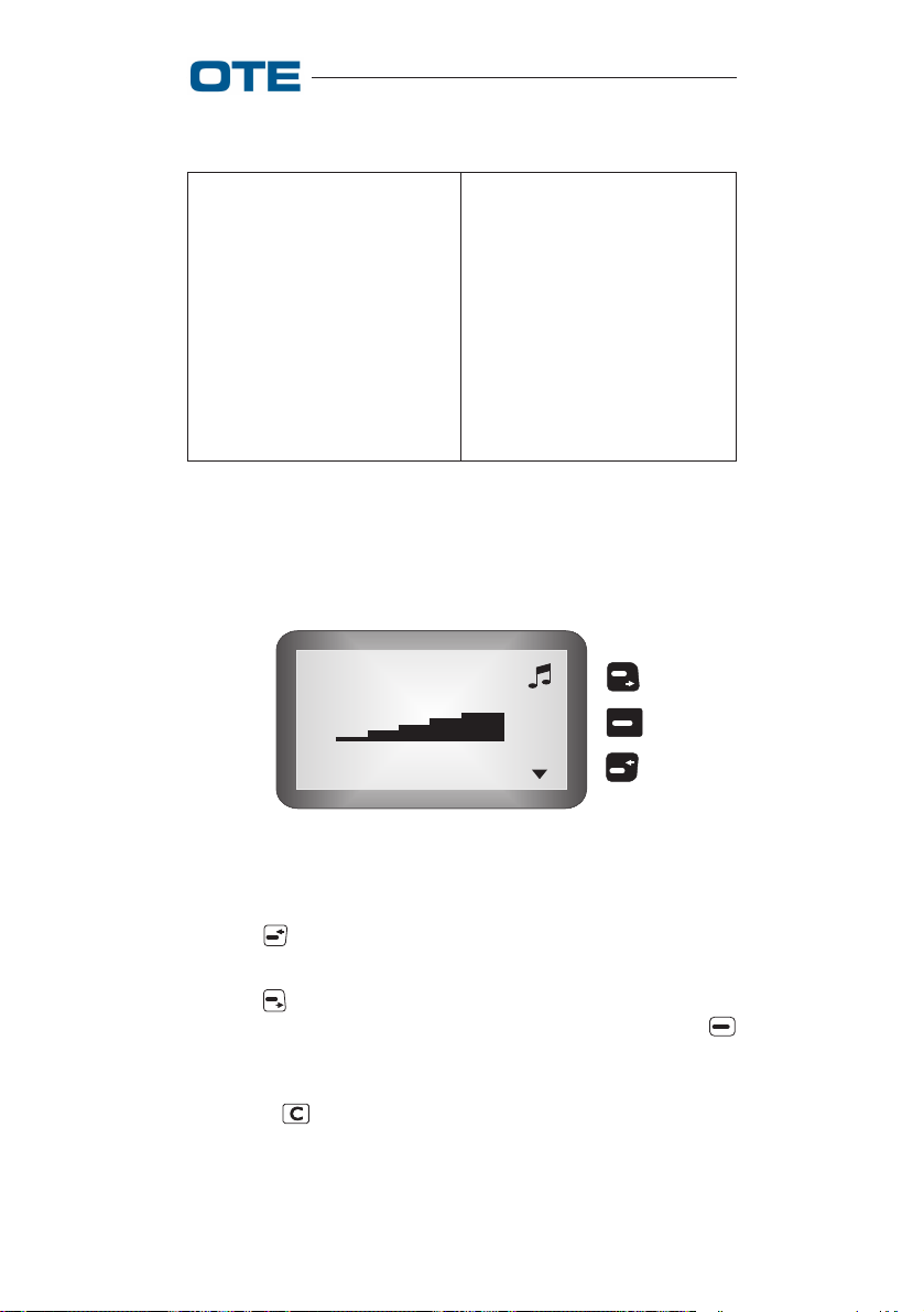
Entering the menu, the graphic scale relative to the current
volume setting relative to the audio signal selected is displayed (see fig. 2.47).
Key Click
O
K
Fig. 2.47 - Sounds Volume Visualization
Use the key to scroll through the audio signals in circular
fashion.
Use the key to scroll through the volume levels in circular
fashion and to activate the audio signals demo; use the
key, associated with "OK", to confirm the modifications,
which will be maintained even after the terminal is turned off.
With the key it is possible to exit the menu without
modifications.
779-0217/03.04 55
VS 2001 Vehicular Radio Terminal
User’s Guide
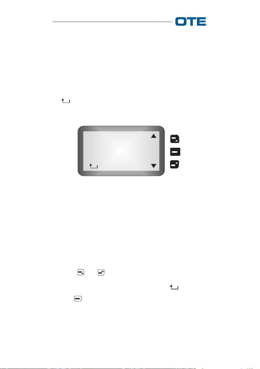
2.1.5.5.4 Backlight
This function allows the user to modify the equipment display and keypad illumination type.
The following items can be selected (see fig. 2.48):
• AUTOM. OFF
• OFF
•ON
• : return to previous menu (see section 2.1.1.5).
Autom. Off
OFF
ON
O
K
Fig. 2.48 - Backlight
In "Autom. Off " mode, the display and keypad lights are
turned on when the keys are pressed or when an event occurs
(rotating knob for group selection, arrival of a call, etc.) and
turns off automatically after a time configurable from PRP.
In "ON" mode, the display and keypad lights are always on,
while in "OFF" mode, they are always off.
With the and keys, the option is selected and a demo
of the selected setting is automatically activated (to see the
demo relative to the current setting, select " ").
Use the key, associated with "OK", to modify the type of
lighting; the selection is maintained even after the terminal
is turned off.
56 779-0217/03.04
VS 2001 Vehicular Radio Terminal
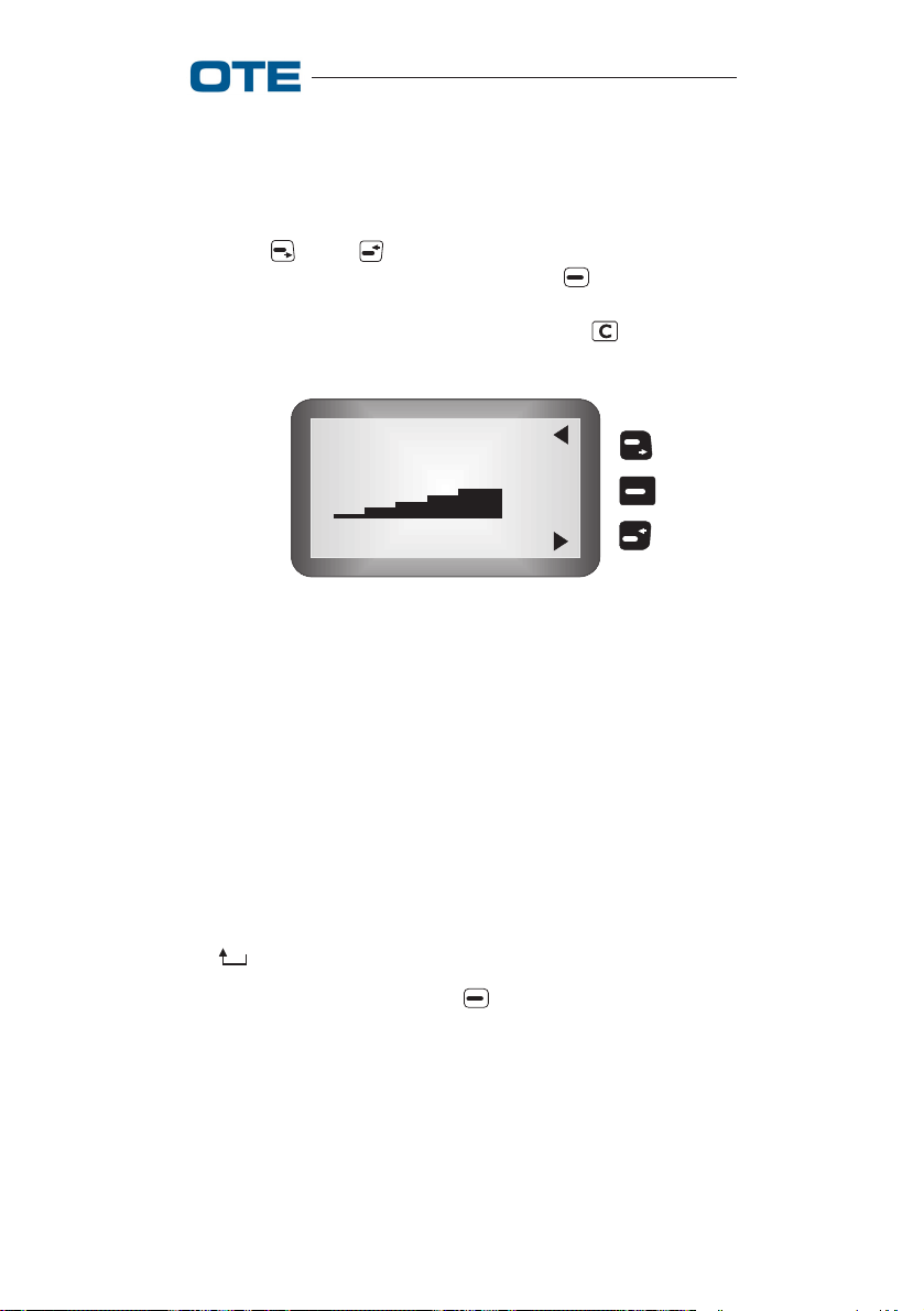
2.1.5.5.5 LCD Contrast
User’s Guide
This function allows the user to modify the display contrast.
Entering the menu, the graphic scale corresponding to the
current setting is visualized (see fig. 2.49).
Use the and keys to select the contrast level and
automatically activate a demo ; use the key, associated
with "OK", to confirm the selection, which will be maintained
even after the terminal is turned off. The key allows
exiting the menu without modifications.
LCD Contrast
O
K
Fig. 2.49 - Contrast
2.1.5.6 Aux Microp.
This menu allows the user to set the equipment auxiliary
microphone configuration.
To access auxiliary microphone menu, select SETTINGS →
AUX MICROP. from the main menu.
The following items can be selected:
• NO AUX. MIC.
• HANDS FREE
• FRONT PANEL
• : return to previous menu (see section 2.1.1.5).
After selection using the key , associated with "OK" the
auxiliary microphone is changed, and the selection is maintained even after the terminal is turned off.
If "No Aux. Mic." is chosen, when the user tries to press the
extern PTT a temporary message will appear.
NOTE: "Hands free" option is not available in motorcycle
configuration.
779-0217/03.04 57

VS 2001 Vehicular Radio Terminal
User’s Guide
2.1.5.7 Full Duplex
This menu allows the user to set the equipment microphone
configuration.
To access full duplex menu select SETTINGS → FULL
DUPLEX from the main menu.
The following items can be selected:
• HANDS FREE
• FRONT PANEL
• LEMO/HELMET
• : return to previous menu (see section 2.1.1.5).
After selection using the key associated with "OK" the
microphone configuration is changed, and the selection is
maintained even after the terminal is turned off.
NOTE: "Hands free" and "Lemo" options are not available
in motorcycle configuration. "Helmet" mode is not available
in car configuration.
2.1.5.7.1 Hands Free
To access hands free menu select SETTINGS → FULL DUPLEX → HANDS FREE from the main menu.
The following items can be selected:
• REAL FD
• PSEUDO FD
• : return to previous menu (see section 2.1.1.5).
2.1.5.7.2 Front Panel
To access front panel menu select SETTINGS → FULL DUPLEX → FRONT PANEL from the main menu.
The following items can be selected:
• REAL FD
• PSEUDO FD
• : return to previous menu (see section 2.1.1.5).
58 779-0217/03.04

VS 2001 Vehicular Radio Terminal
User’s Guide
2.1.5.7.3 Lemo/Helmet
This menu allows the user to enable/disable Helmet/Lemo
modality. Helmet in case of motorcycle and Lemo in case of
car configuration.
Entering this menu the user will be asked to modify the
current status. To confirm the choice press the key corresponding to "YES". By pressing the key, or the key corresponding to "NO", the change has no effect.
2.1.6 Help
To access the Help function, select → HELP from the main
menu.
This function allows the user to visualize a list of some
equipment functions, such as:
• direct access keys;
• dialling digits;
• supplementary services.
The direct access key functions are shown in tab. 2.3.
Tab. 2.3 Direct Access Keys
KEY FUNCTION
0 Ch. Mode (if enable)
1 Encryption (if enable)
2 Working Profiles
3 Group Scanning
4 Text Messages
5 Late Entry (if enable)
6 Tx Inhi. (if enable)
7 Equip. Info.
8—
9—
#
*
779-0217/03.04 59
Call Priority
—

VS 2001 Vehicular Radio Terminal
User’s Guide
NOTE: To access the quick functions, keep the corresponding key pressed for about 2 sec.
The dialling digits are shown in tab. 2.4.
The supplementary services are shown in tab. 2.5.
Tab. 2.4 Dialling Digits
DIGIT DESCRIPTION
0 Def. GTW (if enabled)
# 1 n GTW n (n=0, ..., 9)
# 5 Generic Gateway
# 6 Home TETRA Netw.
# 7 Sh. Home T. Network
# 8 Short Number Add.
# 9 External T. Netw.
Tab. 2.5 Supplementary services
SUPPLEMENTARY
SERVICE
Status Message * 00 # SN #
Priority Call (level 11) * 15 #
Priority Call (level 10) * 150 #
Priority Call (level 1÷9) * 151 # ÷ * 159 #
Pre-emptive Priority Call * 211 #
(level 1)
Pre-emptive Priority Call * 212 #
(level 2)
Pre-emptive Priority Call * 213 #
(level 3)
ABBREVIATION
2.1.7 Return to Previous Menu
See section 2.1.1.5.
60 779-0217/03.04

VS 2001 Vehicular Radio Terminal
User’s Guide
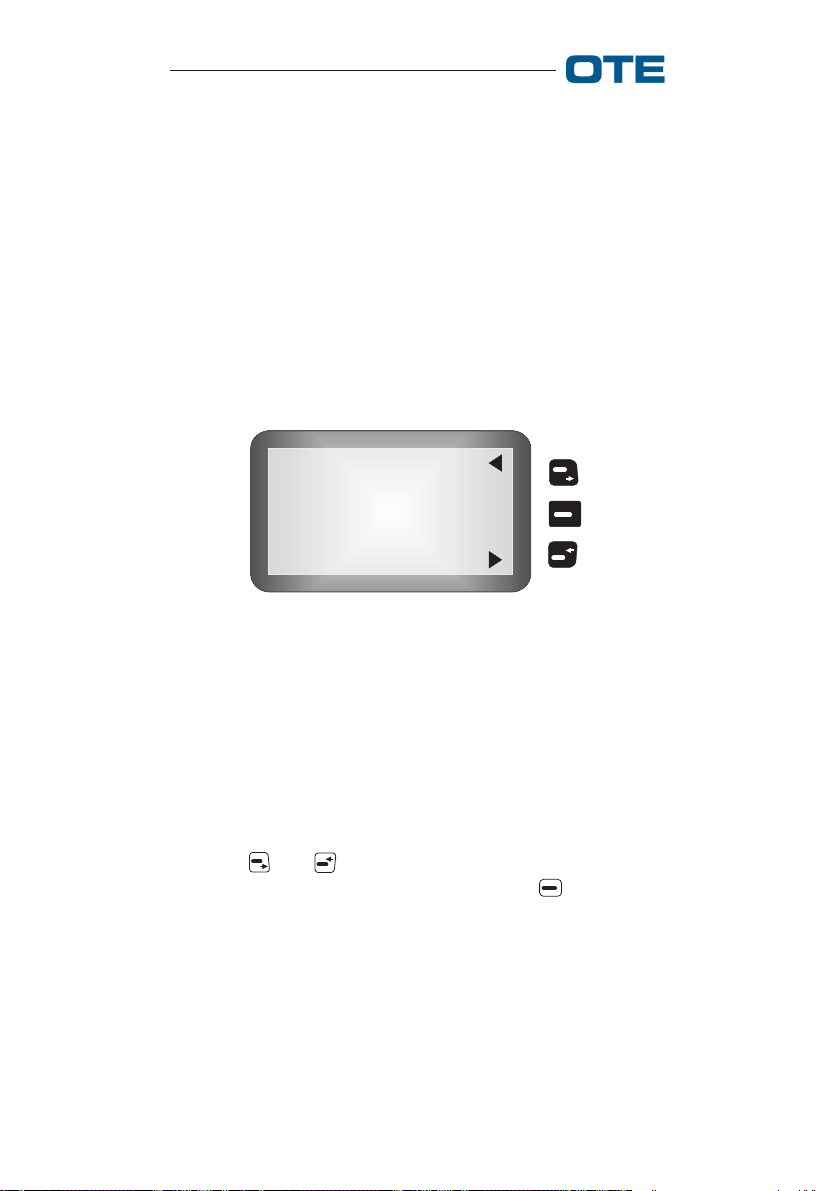
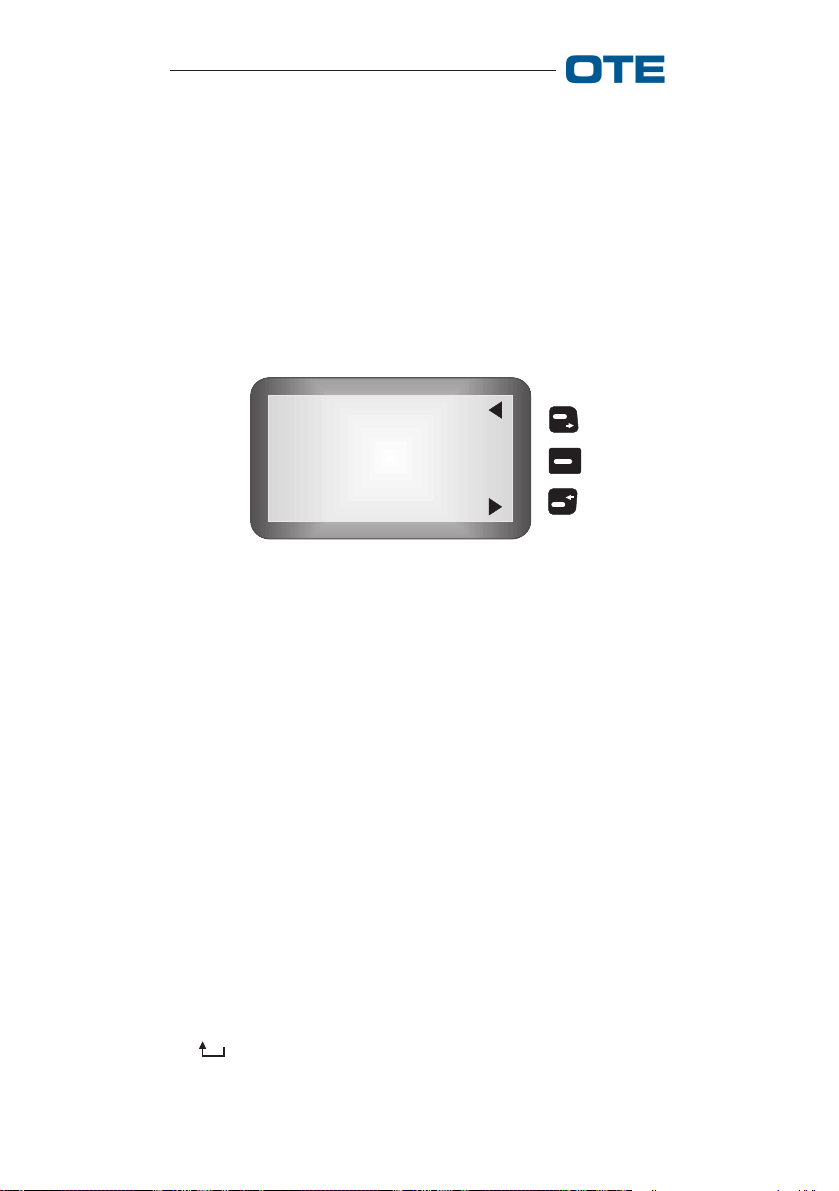
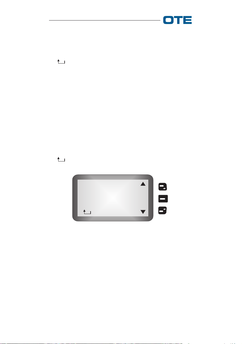
2.2 Main Direct Mode (DMO) Menu
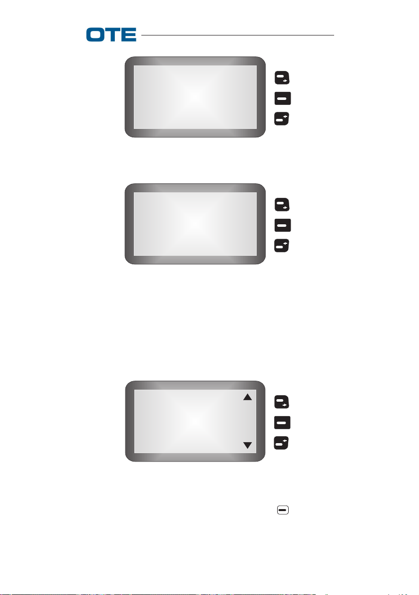
In Direct Mode the screen appears as shown in fig. 2.50. To
access the menu, after having turned on the radio, press the
key.
D
Free
Group 200
Fig. 2.50 - Mode (DMO)
NOTE: In area 3 of the terminal display, the symbols
(send status messages, see section 2.2.1.4) and (phone
lists, see section 2.2.4) appear on the bottom and upper part
of the screen, respectively.
M
E
N
U
The following items can be selected (see fig. 2.51):
Messages
Change Mode
Encryption
Phone Lists
Settings
S
E
L
Help
Fig. 2.51 - Menu (DMO)
779-0217/03.04 61

VS 2001 Vehicular Radio Terminal
User’s Guide
• MESSAGES
• CHANGE MODE
• ENCRYPTION
• PHONE LISTS
• SETTINGS
• HELP
• : return to previous menu.
2.2.1 Messages
See section 2.1.1.
2.2.1.1 In Box
See section 2.1.1.1.
2.2.1.2 Out Box
See section 2.1.1.2.
2.2.1.3 Text Messages
See section 2.1.1.3.
2.2.1.4 Send Status
See section 2.1.1.4.
2.2.1.5 Return to Previous Menu
This function, represented in the menu with the symbol
" ", indicates the completion of the possible selections and
allows, if selected, returning to the upper menu level. The
same function can be obtained by pressing the key from
the menu.
62 779-0217/03.04

VS 2001 Vehicular Radio Terminal
User’s Guide
2.2.2 Change Mode
To access the modes, select the Change Mode function from
the main menu.
Now, the following question is shown: "change in trunked?",
you can answer "YES" or "NO" by the corresponding keys.
NOTE: It is possible to access this menu even by pressing
the M key.
2.2.3 Encryption
See section 2.1.3.
2.2.3.1 E2EE status
See section 2.1.3.1.
2.2.3.2 E2EE key
See section 2.1.3.2.
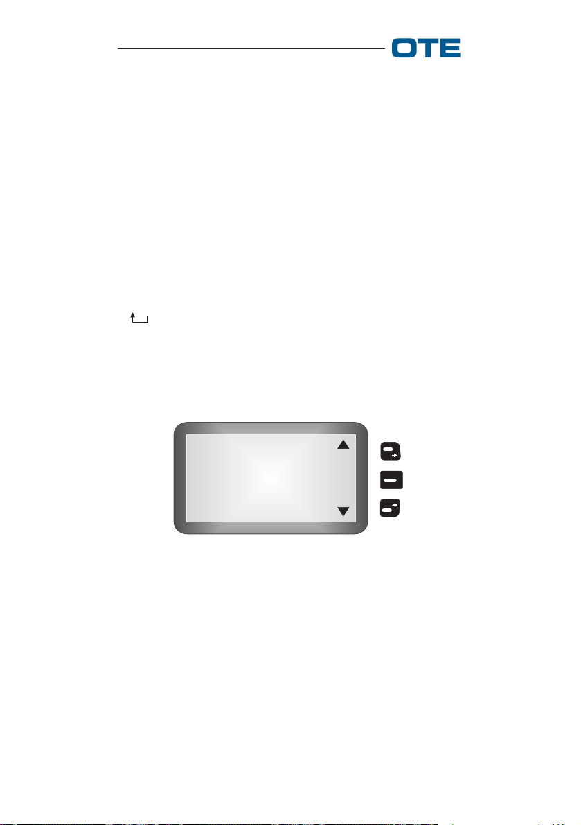
2.2.4 Phone Lists
To access the phone lists, select the → PHONE LISTS function from the main menu.
The following items can be selected (see fig. 2.52):
Phone Book
Home Tetra
Fig. 2.52 - "Phone Lists" Menu
779-0217/03.04 63
S
E
L
VS 2001 Vehicular Radio Terminal
User’s Guide
• PHONE BOOK: new users, directory and possibility of
modifying and deleting;
• HOME TETRA: Tetra users entered from PRP;
• : return to previous menu (see section 2.2.1.5).
2.2.5 Settings
To access the settings, select the → SETTINGS function from
the main menu..
The following items can be selected (see fig. 2.53):
• GROUP MNG.
• CALLS
• PREFERENCES
• AUX. MICROP.
• : return to main menu (see section 2.2.1.5).
Group Mng
Calls
Preferences
Aux. Microp.
S
E
L
Fig. 2.53 - "Settings" Menu (DMO)
2.2.5.1 Group MNG
See section 2.1.5.1.
2.2.5.1.1 Group Scan
See section 2.1.5.1.1.
64 779-0217/03.04
VS 2001 Vehicular Radio Terminal
2.2.5.1.2 WPS Select
User’s Guide
See section 2.1.5.1.2.
2.2.5.1.3 WPS Update
See section 2.1.5.1.3.
2.2.5.1.4 WPS Reconf.
See section 2.1.5.1.4.
2.2.5.2 Calls
To access the calls, select the SETTINGS → CALLS function
from the main menu.
The following items can be selected (see fig. 2.54):
• LATE ENTRY
• CALL
• DIAL MODE
• : return to previous menu (see section 2.2.1.5).
Late Entry
Call
Dial Mode
S
E
L
Fig. 2.54 - "Calls" Menu ( DMO)
2.2.5.2.1 Late Entry
See section 2.1.5.2.1.
779-0217/03.04 65
VS 2001 Vehicular Radio Terminal
User’s Guide
2.2.5.2.2 Call
To access the call function, select SETTINGS→ CALLS→
CALL from the main menu. This menu allows the user to
configure the services associated with call management.
The following items can be selected (see fig. 2.55):
• COMMUNICAT.: This menu allows the user to modify
the type of default individual call, configurable from PRP
(with ack/without ack). Entering the menu, the first item
shown corresponds to the current setting; selecting the
key associated with "OK" changes the mode; the new
value will be maintained even after the terminal is turned
off.
• SEND TPNI: This menu allows the user to enable/disable the sending of the TPNI (Transmitting Party Number
Identification, configurable from PRP) in voice calls.
Entering the menu, modification of the current status is
requested. If the TPNI is disabled, you are requested to
enable it, and vice versa.
The key or the key associated with "NO" return to
the previous level without changing the status. The key
associated with "YES" confirms the change and the new
status will be maintained even after the terminal is turned
off.
• : return to previous menu (see section 2.2.1.5).
Communicat.
Send TPNI
S
E
L
Fig. 2.55 - "Call" Menu
66 779-0217/03.04

VS 2001 Vehicular Radio Terminal
2.2.5.2.3 Dial Mode
User’s Guide
This function allows the user to change the default dialling
mode configured from PRP.
The following items can be selected (fig. 2.56):
• HOME TETRA: a complete SSI (Short Subscriber Identity) is to be specified. An SSI address consists of 7 or 8
digits, depending on the configuration by PRP. If the
number of digits entered is less than the SSI length, the
specified portion is regarded as the least significant digits
and the address is completed with 0s (i.e. SSI length=7
and 123 is entered then 0000123 is the called address).
• SHORT HOME TETRA: either a partial or a complete SSI
can be specified. If the number of digits entered is less
than the SSI length, the specified portion is regarded as
the least significant digits. In this case the address is
completed on the basis of a predefined SSI locally stored
on the terminal.
• EXT.TETRA: the address to be specified is a complete
TSI (Tetra Subscriber Identity). It is composed by three
main parts: MCC (Mobile Country Code, 3 digits), MNC
(Mobile Network Code 4 or 5 digits configured by PRP)
and the SSI.
The TSI is comprehensive of a gateway identification in
order to issue the call outside the network (the gateway
id. is implicit in the TSI and depends on the network
numbering scheme).
• : return to previous menu (see section 2.2.1.5).
Home Tetra
Short Home
Ext. Tetra
O
K
Fig. 2.56 - Dial Mode
779-0217/03.04 67

VS 2001 Vehicular Radio Terminal
User’s Guide
2.2.5.3 Preferences
See section 2.1.5.5.
2.2.5.3.1 PIN
See section 2.1.5.5.1.
2.2.5.3.2 Language
See section 2.1.5.5.2.
2.2.5.3.3 Sounds
This function allows the user to disable or modify the volume
of the equipment's audio signals. The items that can be selected in DMO are shown in tab. 2.6.
Tab. 2.6 Selectable Sounds Items (DMO)
Key click
Alarm Tone
Failure tone
Success tone
Emerge. tone
Conversation
Unprotec. Tx
Incom Data
Channel Free
Call End
Err. Sequen.
Entering the menu, the graphic scale relative to the current
setting of the selected audio signals is visualized (see fig.
2.57).
Use the and keys to increase and decrease the audio
signal tone; a screen like the one seen in fig. 2.57 appears on
the display. Precisely, the key scrolls through the volume
levels in circular fashion and activates the audio signal
demo; the key scrolls through the audio signals in circu-
68 779-0217/03.04
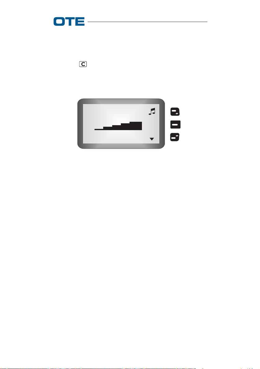
VS 2001 Vehicular Radio Terminal
User’s Guide
lar fashion; use the key associated with "OK" to confirm the
changes, which will be maintained even after the terminal is
turned off.
With the key, it is possible to exit the menu without
modifications.
Key Click
O
K
Fig. 2.57 - Visualization of Sounds Volume
2.2.5.3.4 Backlight
See section 2.1.5.5.4.
2.2.5.3.5 LCD Contrast
See section 2.1.5.5.5.
2.2.5.4 Aux. Microp.
See section 2.1.5.6.
2.2.6 Help
This function allows the user to display the list of direct
access keys (see tab. 2.7).
779-0217/03.04 69
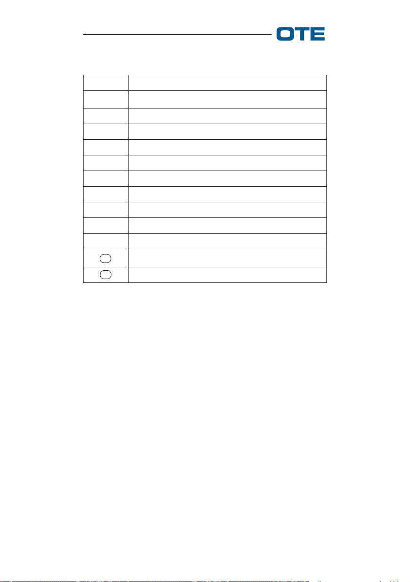
VS 2001 Vehicular Radio Terminal
User’s Guide
Tab. 2.7 Direct Access Keys (DMO)
KEY FUNCTION
0 Change Mode (if enable)
1 Encryption (if enable)
2 Working Profiles
3 Group Scanning
4 Text Messages
5 Late Entry (if enable)
6 Tx Inhi. (if enable)
7 Equipment Info.
8—
9 Open Grp. Call
#
*
Call Priority
—
NOTE: To access the quick functions, keep the corresponding key pressed for about 2 sec.
2.2.7 Return to Previous Menu
See section 2.2.1.5.
70 779-0217/03.04

VS 2001 Vehicular Radio Terminal
User’s Guide
2.3 Technical characteristics
maintenance and problem
solving
For the vehicular radio technical characteristics, maintenance
and problem solving please refer to the relative Technical
Manual.
779-0217/03.04 71

VS 2001 Vehicular Radio Terminal
User’s Guide
3. Standard references and
safety recommendations
In this section all the indications and recommendations for
the vehicular radio safe use are reported.
3.1 Standard references
The Tetra vehicular radio is designed and manufactured to
comply with the applicable standard and regulations covering the following areas of product safety:
• conformance to ETSI TETRA standard;
• electromagnetic compatibility and interference (EMC/
EMI);
• electrical safety (low voltage);
• health effects of electromagnetic fields.
3.2 Safety recommendations
Carefully read all of the cautions and warnings before using
the radio:
Do not use the radio equipment for uses different
than those indicated in the manual.
For a correct use of the radio equipment, read what
is listed in this user's guide.
Protect the radio from sprinklings of water and/or
other liquids and from dust.
Be careful not to damage the vehicular radio when
cleaning the vehicle.
72 779-0217/03.04
VS 2001 Vehicular Radio Terminal
User’s Guide
Do not use the vehicular radio if the antenna and/
or the antenna cable are damaged.
The electronic devices are sensitive to electromagnetic interference (EMI) if not adequately shielded, designed or configured differently for electromagnetic fields immunity.
If electromedical equipment (ex. pace-makers,
acoustical equipment, etc.) is used together with
the vehicular radio, make sure that it is adequately
shielded from external electromagnetic fields.
Do not take the radio into environments that have
a potentially explosive atmosphere (ex. fuel storage sites, filling stations, etc.).
Install the vehicular radio following the instructions given in the technical handbook. The equipment must be installed in such a way that it
complies with the national regulations in effect.
Carry out the maintenance interventions on the
vehicular radio following the instructions given in
the technical handbook.
Follow all accident prevention standards when carrying out maintenance interventions on the vehicular equipment and use the proper tools (spanners, screwdrivers).
First and second maintenance level interventions
on the equipment are to be carried out by authorized technicians only.
Third maintenance level interventions are to be
carried out by OTE technicians only.
779-0217/03.04 73

VS 2001 Vehicular Radio Terminal
User’s Guide
Use only original accessories and spare parts, or
approved by the manufacturer, suitable for the
vehicular radio. The use of different accessories
and/or spare parts (earphone, antenna, etc.) makes
the safety and electromagnetic compatibility certifications to be valid no more and it could lower
the user safety level and/or generate electromagnetic fields that exceed the accepted limits.
After the radio has been trasmitting for a long
period, it may reach high temperatures: in such a
WARNING
case avoid touching the radio shell.
The emergency call is a priority type call.
The vehicular radio, like all mobile telephony
equipment, operates with radio frequency signals,
therefore, the forwarding of the call depends on the
network coverage at the moment of the call.
If you need send an emergency call, keep pressed
the emergency button for at least 2 seconds.
The E-WHERE is only suitable for vehicles with
the negative pole of the battery earthed to bodywork. Installation on other vehicles can cause
faults and damage/fire to cables.
The radio complies with all product specifications and great
care is taken by the manufacturer so that user safety, as far
as the effects of electromagnetic waves on health are concerned, is guaranteed within the limits established by the international specifications.
74 779-0217/03.04

VS 2001 Vehicular Radio Terminal
User’s Guide
3.3 ESD Precautions
No ESD precautions have to be taken by the operator. VS
2001 and its ancillary parts are designed and manufactured
in such a way to not be sensible to electrostatic discharges
according to what referred in the EN 301 489-18.
779-0217/03.04 75

VS 2001 Vehicular Radio Terminal
User’s Guide
Appendix A: Accessories
Introduction
During a call it is possible to change the accessory through
which listen/talk.
In this appendix is explained how to make this change,
according to three different accessories configurations:
1. Motor vehicle configuration: Handset, Handsfree, External Loudspeaker.
2. Motor vehicle configuration: Lemo, Handsfree, External
Loudspeaker.
3. Motor cycle configuration: Handset, Helmet, Handsfree,
External Loudspeaker.
Some remarks valid for each configuration which includes
handsfree
If the chosen configuration is of handsfree type, with external
loudspeaker, to avoid echo problems in full duplex modality,
microphone and loudspeaker can’t be active at the same time
(pseudo full duplex).
If the external loudspeaker is active and the microphone is
not active, a PTT pressure, activates the relevant microphone;
releasing the PTT the external lousdpeaker is put back into
service.
The key has always the only functionality of ceasing the
call if a call is already active or to refuse it if an On/Off Hook
call is coming.
The key has always the functionality of accepting a call
(if it is an On/Off Hook call) or to send it.
By means of the key it is possible to change configuration, choosing from the menu. The first item in the menu list
is the current configuration.
If only one configuration is available, the menu is not shown
and the key has no functionality.
76 779-0217/03.04

VS 2001 Vehicular Radio Terminal
User’s Guide
Once the call has been accepted, the transitions from one
configuration to the other, for On/Off Hook or direct calls, are
the same.
1. Motor vehicle configuration: Handset, Handsfree, External Loudspeaker
Accepting a call (Half or Full Duplex)
If the call is of On/Off Hook type, the call signalling goes to
the external loudspeaker.
The call can be accepted pressing:
1. key (external loudspeaker and no active microphone)
2. external PTT (handsfree microphone and external loudspeaker)
3. handset PTT (unhooked) (handset microphone and loudspeaker)
Changing configuration
It is possible to exit the handset configuration only through
the key. It is possible to go to handset configuration from
handsfree configuration even by unhooking the handset.
NOTE: The handset hooking leads to a call ceasing only
if both handset microphone and handset loudspeaker are
active. If the handset is unhooked when the call is coming,
a following handset hoooking doesn’t lead to the call ceasing. In fact if the handset is not hooked when the call is
coming, the handset can’t be used until it is hooked again.
In half duplex modality it is also possible to use the handset
microphone and the external loudspeaker; to get this configuration you have to press the handset PTT from the external
audio and handsfree microphone configuration. To return to
use the handsfree microphone you only have to hook the
handset again.
NOTE: To avoid external bothers, during a call with active handset the external PTT pressing has no effect.
779-0217/03.04 77

VS 2001 Vehicular Radio Terminal
User’s Guide
2. Motor vehicle configuration: Lemo, Handsfree, External Loudspeaker
Accepting a call (Half or Full Duplex)
The call (On/Off Hook) can be accepted by pressing:
1. key (no active microphone)
2. Lemo PTT (Lemo microphone active)
3. External PTT (handsfree microphone active)
Changing configuration
The active microphone is the default one (usually handsfree),
until the other PTT is pressed (usually Lemo), once this is
released, the active microphone is the default one again.
In this configuration the audio signal goes always to the
external loudspeaker, because it is the only possible one.
NOTE: In this configuration the key has no functiona-
lity.
3. Motor cycle configuration: Handset, Helmet, Handsfree, External Loudspeaker
Accepting a call (Half or Full Duplex)
Unhooking the handset,when a call is coming,the handset
microphone and loudspeaker are active, whether if the helmet
is active or not.
If the helmet is active, both external PTT and key pressing, activates the helmet microphone and loudspeaker. If the
helmet is not active and the handset is hooked, the external
PTT pressing or the key pressing activates the external
microphone and loudspeaker.
NOTE: In motor cycle configuration, as handsfree microphone we mean the panoramic one, included in FPG1/A
panel. The handset is the one suitable for motor cycle configuration.
78 779-0217/03.04

VS 2001 Vehicular Radio Terminal
User’s Guide
If the helmet is active, the audio output goes by default to
the helmet, otherwise if the helmet is not active the audio
output goes to the external loudspeaker.
Changing configuration
By means of the key, it is possible, from any configuration (handset, helmet,handsfree) to go to any of the two not
active one.
For instance, if handset microphone and loudspeaker are
active, it is possible to activate, by means of the key, the
helmet or handsfree microphone and loudspeaker.
NOTE: It is user responsibility to be sure that the helmet
is really connected before passing to the helmet modality.
Handset unhooking while a call is already active automatically activates the handset microphone and loudspeaker.
External PTT pressing, with active helmet and while using
the handset, automatically activates the helmet microphone
and loudspeaker.
While using handsfree configuration, in pseudo full duplex
modality, the loudspeaker and the microphone are alternatively active. It is possible to choose which microphone to use
by pressing the relevant PTT. Releasing the PTT the external
loudspeaker is active again.
779-0217/03.04 79

 Loading...