


VS 2001
UHF Vehicle Radio
Equipment
Technical Handbook
Document code: 779-0373/02
Revision 02

VS 2001
Technical Handbook
The information in this document is subject to change without notice and describes only the product defined in the
introduction of this documentation. This document is intended for the use of OTE’s customers only for the purposes
of the agreement under which the document is submitted, and no part of it may be reproduced or transmitted in any
form or means without the prior written permission of OTE. The document has been prepared to be used by
professional and properly trained personnel, and the customer assumes full responsibility when using it. OTE
welcomes customer comments as part of the process of continuous development and improvement of the
documentation.
The information or statements given in this document concerning the suitability, capacity, or performance of the
mentioned hardware or software products cannot be considered binding but shall be defined in the agreement made
between OTE and the customer. However, OTE has made all reasonable efforts to ensure that the instructions
contained in the document are adequate and free of material errors and omissions. OTE will, if necessary, explain
issues which may not be covered by the document.
OTE liability for any errors in the document is limited to the documentary correction of errors. OTE WILL NOT BE
RESPONSIBLE IN ANY EVENT FOR ERRORS IN THIS DOCUMENT OR FOR ANY DAMAGES, INCIDENTAL
OR CONSEQUENTIAL (INCLUDING MONETARY LOSSES), that might arise from the use of this document or the
information in it.
This document and the product it describes are considered protected by copyright according to the applicable laws.
Other product names mentioned in this document may be trademarks of their respective companies, and they are
mentioned for identification purposes only.
Copyright © OTE S.p.A. 2003. All rights reserved.
OTE S.p.A.
A Finmeccanica Company
Via E. Barsanti 8, 50127 - Firenze, Italy
Phone: +39 55 43811, Fax: +39 55 4381426
Page ii OTE Proprietary Information
P/N: 779-0373/02
Revision 02

VS 2001
Technical Handbook
Safety rules
Safety rules
Before using the equipment, read all the instructions contained in the
manual and with special care those relative to safety.
Lue käyttöohjeet ja erityisesti turvallisuuteen liittyvat ohjeet ennen
laitteen käyttöä.
Alvorens over te gaan tot het gebruik van het apparaat lees met
aandacht al de instructies van het handboek en let vooral op die die de
veiligheid betreffen.
Alvorens het apparaat in gebruik te nemen lees alle instructies van het
handboek en vooral de voorschriften betreffende de veiligheid.
Avant toute utilisation de l’appareil, lire toutes les indications
contenues dans le Manuel et avec une attention particulière celles
relatives à la sécurité.
Läs alla instruktioner i denna manual innan ni använder apparaten och
då särskilt noggrannt de anvisningar som gäller säkerheten.
Læs alle de vejledninger, der er indeholdt i manualen med særlig
opmærksomhed på de vejledninger, der vedrører sikkerheden, før
apparatet tages i brug.
P/N: 779-0373/02
Revision 02
Vor Gebrauch des Geräts alle in dieser Bedienungsanleitung
enthaltenen Anweisungen und Vorschriften lesen.
Den Sicherheitsbestimmungen ist dabei besondere Aufmerksamkeit
zu widmen.
Marconi Proprietary information
Page iii

VS 2001
Technical Handbook
Safety rules
Πριν χρησιµοποιήσετε τη συσκευή διαβάστε όλες τις οδηγίες που
περιέχονται στο εγχειρίδιο και δώστε ιδιαίτερη προσοχή στης
οδηγίες ασφαλείας.
Prima di utilizzare l’apparecchiatura leggere tutte le indicazioni
contenute nel manuale e con particolare attenzione quelle relative alla
sicurezza.
Antes de utilizar el equipo leer todas las instrucciones contenidas en
el manual, poniendo particular atención a las de seguridad.
Antes de utilizar o aparelho, leia todas as instruções que constam no
manual e com muita atenção as instruções relativas à segurança.
Page iv Marconi Proprietary information
P/N: 779-0373/02
Revision 02

VS 2001
v
Technical Handbook
Safety rules
This equipment is marked
According to the requirements specified in the R&TTE directive 1999/5/EC and the
Commission Decision 6th April 2000, the EC marking is accompanied by the Class
II equipment class identifier.
This equipment is intended for sell and use in Austria, Belgium, Denmark, Finland,
France, Germany, Greece, Ireland, Italy, Luxembourg, Portugal, Spain, Sweden,
The Netherlands, United Kingdom.
This equipment requires authorization or license for use.
This equipment operates on frequency bands non-harmonised in the EU.
This equipment can also be used worldwide where the equipment is approved for
use.
P/N: 779-0373/02
Revision 02
Marconi Proprietary information
Page

VS 2001
Technical Handbook
Safety rules
PAGE INTENTIONALLY LEFT BLANK
Page vi Marconi Proprietary information
P/N: 779-0373/02
Revision 02

VS 2001
Technical Handbook
Safety rules
Hereby, OTE S.p.A., declares that this VS 2001 is in compliance with the essential
requirements and other relevant provisions of Directive 1999/5/EC.
OTE S.p.A. vakuuttaa täten että VS 2001 tyyppinen laite on direktiivin 1999/5/EY
oleellisten vaatimusten ja sitä koskevien direktiivin muiden ehtojen mukainen.
Hierbij verklaart OTE S.p.A. dat het toestel VS 2001 in overeenstemming is met de
essentiële eisen en de andere relevante bepalingen van richtlijn 1999/5/EG.
Bij deze verklaart OTE S.p.A. dat deze VS 2001 voldoet aan de essentiële eisen
en aan de overige relevante bepalingen van Richtlijn 1999/5/EC.
Par la présente, OTE S.p.A. déclare que ce VS 2001 est conforme aux exigences
essentielles et aux autres dispositions de la directive 1999/5/CE qui lui sont
applicables.
Härmed intygar OTE S.p.A. att denna VS 2001 står I överensstämmelse med de
väsentliga egenskapskrav och övriga relevanta bestämmelser som framgår av
direktiv 1999/5/EG.
Undertegnede OTE S.p.A. erklærer herved, at følgende udstyr VS 2001 overholder
de væsentlige krav og øvrige relevante krav i direktiv 1999/5/EF.
Hiermit erklärt OTE S.p.A. die Übereinstimmung des Gerätes VS 2001 mit den
grundlegenden Anforderungen und den anderen relevanten Festlegungen der
Richtlinie 1999/5/EG.
ΜΕ ΤΗΝ ΠΑΡΟΥΣΑ OTE S.p.A. ∆ΗΛΩΝΕΙ ΟΤΙ [type of equipment]
ΣΥΜΜΟΡΦΩΝΕΤΑΙ ΠΡΟΣ ΤΙΣ ΟΥΣΙΩ∆ΕΙΣ ΑΠΑΙΤΗΣΕΙΣ ΚΑΙ ΤΙΣ ΛΟΙΠΕΣ
ΣΧΕΤΙΚΕΣ ∆ΙΑΤΑΞΕΙΣ ΤΗΣ Ο∆ΗΓΙΑΣ 1999/5/ΕΚ.
Con la presente OTE S.p.A. dichiara che questo VS 2001 è conforme ai requisiti
essenziali ed alle altre disposizioni pertinenti stabilite dalla direttiva 1999/5/CE.
Por medio de la presente OTE S.p.A. declara que el VS 2001 cumple con los
requisitos esenciales y cualesquiera otras disposiciones aplicables o exigibles de
la Directiva 1999/5/CE.
OTE S.p.A. declara que este VS 2001 está conforme com os requisitos essenciais
e outras disposições da Directiva 1999/5/CE.
PAGE INTENTIONALLY LEFT BLANK
P/N: 779-0373/02
Revision 02
Marconi Proprietary information
Page vii

VS 2001
Technical Handbook
Safety rules
PAGE INTENTIONALLY LEFT BLANK
Page viii Marconi Proprietary information
P/N: 779-0373/02
Revision 02

VS 2001
Technical Handbook
Summary
Summary
LIST OF ACRONYMS ............................................................................XVII
REFERENCE REGULATIONS .............................................................. XXVII
1. GENERAL INFORMATION .................................................................... 1
1.1 INTRODUCTION ...............................................................................................................1
1.2 TETRA NETWORK OVERVIEW .......................................................................................2
1.1.1 TETRA network equipment................................................................................5
1.1.1.1 Radio Base Station (BS) ....................................................................5
1.1.1.2 Switching and Control Node (SCN)....................................................5
1.1.1.3 Network Management System (NMS)................................................5
1.1.1.4 Control Room Server (CRS)...............................................................5
1.1.1.5 WDS, RDS and LDS ..........................................................................5
1.1.1.6 Terminals: fixed stations, vehicular and hand-held radios.................6
1.1.2 Reference standard ...........................................................................................6
1.3 GENERAL CHARACTERISTICS ......................................................................................7
1.1.1 E-WHERE/FPG1/A Module ...............................................................................8
1.4 NETWORK APPLICATION................................................................................................9
1.5 CHARACTERISTICS AND OPERATING FUNCTIONS..................................................10
1.6 SERVICES.......................................................................................................................12
1.7 PROGRAMMING THE EQUIPMENT ..............................................................................13
1.8 TECHNICAL CHARACTERISTICS .................................................................................14
1.9 MAIN COMPONENTS.....................................................................................................16
1.10 SAFETY RECOMMENDATIONS ....................................................................................17
1.11 ESD PRECAUTIONS ......................................................................................................19
2. TECHNICAL DESCRIPTION................................................................ 21
2.1 INTRODUCTION .............................................................................................................21
2.2 GENERAL DESCRIPTION..............................................................................................21
2.2.1 VS 2001 connectors overview .........................................................................21
2.3 RADIO UNIT FUNCTIONAL DESCRIPTION ..................................................................23
2.3.1 Base Band card ...............................................................................................25
2.3.1.1 External connector ...........................................................................27
2.3.1.2 Base Band card interfacing ..............................................................28
2.3.1.3 Level Translator................................................................................30
2.3.1.4 Power Unit........................................................................................30
2.3.1.5 I/F Audio ...........................................................................................30
2.3.1.6 Microcontroller..................................................................................31
P/N: 779-0373/02
Revision 02
Marconi Proprietary information
Page ix

VS 2001
Technical Handbook
Summary
2.3.1.7 DSP.................................................................................................. 32
2.3.1.8 ASIC Time Base and PLL................................................................ 33
2.3.2 R/T card........................................................................................................... 34
2.3.2.1 Functional description...................................................................... 36
1.1.1.2 R/T card interfacing ......................................................................... 39
1.1.3 P.A. card.......................................................................................................... 41
1.1.3.1 Functional description...................................................................... 42
1.1.3.2 P.A. card Interfacing ........................................................................ 43
1.4 FPG1/A FRONT PANEL ................................................................................................. 45
1.4.1.1 Control panel architecture................................................................ 45
1.4.1.2 External interfacing .......................................................................... 47
1.5 E-WHERE/FPG1A MODULE.......................................................................................... 48
1.5.1 System Architecture with E-WHERE/FPG1/A Interface ................................. 49
1.5.2 Mechanical description of E-WHERE/FPG1/A Module................................... 49
1.5.3 Pin out connector ............................................................................................ 51
3. INSTALLATION ..................................................................................53
3.1 INTRODUCTION............................................................................................................. 53
3.2 UNPACKING INSTRUCTIONS AND STORAGE, TRANSPORT REQUIREMENTS..... 53
3.2.1 Unpacking ....................................................................................................... 53
3.2.2 Storage............................................................................................................ 53
3.2.3 Repackaging and transport............................................................................. 53
3.3 INSTALLATION CONFIGURATION ............................................................................... 54
3.3.1 Vehicle configuration without E-WHERE / FPG1/A Module ........................... 54
3.3.2 Vehicle configuration with E-WHERE / FPG1/A Module ................................ 55
3.3.3 Motorcycle configuration ................................................................................. 56
3.4 INSTALLATION OF THE CONTROL PANEL................................................................. 57
3.4.1 3.6.1 Installation of the control panel in a car ................................................. 57
3.4.1.1 Installation in the car radio cavity..................................................... 58
3.4.1.2 Installation with adjustable bracket.................................................. 59
3.4.1.3 Installation with lite bracket.............................................................. 61
3.4.2 Installation of the control panel in a motorcycle.............................................. 62
3.5 RADIO UNIT INSTALLATION......................................................................................... 64
3.6 ANTENNA INSTALLATION ............................................................................................ 65
3.7 EXTERNAL CONNECTORS........................................................................................... 66
3.7.1 Antenna connector J18 ................................................................................... 66
3.7.2 Main rear connector (P01) .............................................................................. 66
1.1.3 Front panel connectors ................................................................................... 67
1.1.3.1 Front connectors.............................................................................. 67
1.1.1.2 Rear side connectors....................................................................... 69
1.8 ELECTRICAL CONNECTIONS ......................................................................................72
1.9 E-WHERE/INSTALLATION............................................................................................. 74
1.9.1 Test of E-WHERE/FPG1/A Module................................................................. 74
1.9.2 Cables .............................................................................................................77
Page x Marconi Proprietary information
P/N: 779-0373/02
Revision 02

VS 2001
Technical Handbook
Summary
4. SETTING UP ...................................................................................... 79
4.1 INTRODUCTION .............................................................................................................79
4.2 SETTINGS.......................................................................................................................80
4.2.1 HW/SW Configurations....................................................................................80
4.2.2 Connecting the equipment and the computer..................................................80
4.3 GENERAL DESCRIPTION..............................................................................................81
4.4 PRP PROGRAMMING PACKAGE SERVICE GUIDE ....................................................82
5. DISPOSAL.......................................................................................... 83
5.1 INTRODUCTION .............................................................................................................83
5.2 DISMANTLING AND DISPOSAL ....................................................................................84
5.3 PROVISIONS FOR RE-USE ...........................................................................................85
6. PREVENTIVE MAINTENANCE............................................................. 87
6.1 INTRODUCTION .............................................................................................................87
6.2 COLLECTION OF PREVENTIVE MAINTENANCE FORMS ..........................................88
7. TROUBLESHOOTING ......................................................................... 95
7.1 INTRODUCTION .............................................................................................................95
7.2 RADIO TESTS WITH THE RADIO TEST SET................................................................96
7.2.1 Tests with Radio Test Set................................................................................96
7.3 TROUBLESHOOTING FLOW DIAGRAMS...................................................................103
7.3.1 VS 2001: troubleshooting flow diagrams .......................................................103
7.4 FUNCTIONAL TEST......................................................................................................113
8. CORRECTIVE MAINTENANCE .......................................................... 123
8.1 INTRODUCTION ...........................................................................................................123
8.2 COLLECTION OF CORRECTIVE MAINTENANCE FORMS........................................123
APPENDIX A: ACCESSORIES ..............................................................135
A.1 SUBJECTS TREATED ..................................................................................................135
A.2 MICROPHONE ..............................................................................................................135
A.3 LOUDSPEAKER............................................................................................................137
A.4 VS 2001 ANTENNA.......................................................................................................138
A.5 MAGNETIC HOOK HANDSET......................................................................................139
A.6 MECHANICAL HOOK HANDSET (MAM2000) .............................................................141
A.7 GPS ANTENNA .............................................................................................................143
P/N: 779-0373/02
Revision 02
Marconi Proprietary information
Page xi

VS 2001
Technical Handbook
List of figures
List of figures
Fig. 1.1: TETRA Network Architecture......................................................................................... 4
Fig. 1.2: VS 2001 equipment overview ........................................................................................ 7
Fig. 1.3: E-WHERE/FPG1/A Module ........................................................................................... 8
Fig. 2.1: VS 2001 configuration scheme .................................................................................... 22
Fig. 2.2: Equipment structure: Radio Unit and Front Panel modules ........................................ 23
Fig. 2.3: View from the Base Band card side............................................................................. 24
Fig. 2.4: View from the R/T and P.A. cards side ........................................................................ 24
Fig. 2.5: VS 2001 architecture overview .................................................................................... 25
Fig. 2.6: Base Band functional block diagram ........................................................................... 26
Fig. 2.7: R/T card: arrangement of the sectors .......................................................................... 34
Fig. 2.8: RF section functional block diagram ............................................................................ 35
Fig. 2.9: R/T card block diagram ................................................................................................ 37
Fig. 2.10: Connections between R/T and P.A. cards ................................................................... 39
Fig. 2.11: Connection between R/T card and Base Band card ................................................... 40
Fig. 2.12: J02 description............................................................................................................. 40
Fig. 2.13: Block diagram of the P.A. card .................................................................................... 42
Fig. 2.14: P.A. card interfacing..................................................................................................... 43
Fig. 2.15: Mechanical structure of the Front Panel ......................................................................45
Fig. 2.16: Block diagram of the Front Panel................................................................................. 46
Fig. 2.17: Vehicular Setting-up with E-WHERE/FPG1 Module.................................................... 48
Fig. 2.18: Vehicle configuration with E-WHERE/FPG1/A Module ............................................... 49
Fig. 2.19: E-WHERE/FPG1/A Module ......................................................................................... 49
Fig. 2.20: Scheme of E-WHERE Module ..................................................................................... 50
Fig. 3.1: VS 2001 configuration (installed on a car) without E-WHERE / FPG1/A .................... 54
Fig. 3.2: VS 2001 configuration (installed on a car) with E-WHERE / FPG1/A Module ............ 55
Fig. 3.3: VS 2001 configuration (installed on a motorcycle) ...................................................... 56
Fig. 3.4: Control panel................................................................................................................ 57
Fig. 3.5: Control panel (rear side) ..............................................................................................58
Fig. 3.6: Bracket for control panel (installation in the car radio cavity) ...................................... 58
Fig. 3.7: Adjustable bracket........................................................................................................ 59
Fig. 3.8: Installation of the control panel in the adjustable bracket............................................ 60
Fig. 3.9: Installation of the Control Panel in the lite bracket....................................................... 61
Fig. 3.10: Remote control assembly ............................................................................................ 62
Fig. 3.11: Connection of remote control assembly ...................................................................... 63
Fig. 3.12: Bracket for the Radio Unit module installation ............................................................. 64
Fig. 3.13: Rear view ..................................................................................................................... 66
Fig. 3.14: FPG1/A front connectors ............................................................................................. 68
Fig. 3.15: FPG1/A rear side connector ........................................................................................ 69
Fig. 3.16: Cabling between FPG1/A and accessories ................................................................. 72
Fig. 3.17: Cabling between FPG1/A and Radio Unit module....................................................... 72
Fig. 3.18: Cabling between PC and VS 2001 radio ..................................................................... 73
Page xii Marconi Proprietary information
P/N: 779-0373/02
Revision 02

VS 2001
Technical Handbook
List of figures
Fig. 3.19: E-WHERE / FPG1/A Module ........................................................................................75
Fig. 3.20: E-WHERE Module and E-WHERE Interface with connector .......................................76
Fig. 7.1: Tetra Radio Test Set.....................................................................................................96
Fig. 7.2: SYSTEMS key ..............................................................................................................97
Fig. 7.3: System selection...........................................................................................................97
Fig. 7.4: Channel selection .........................................................................................................98
Fig. 7.5: DATA keys ....................................................................................................................98
Fig. 7.6: Red “ENTER” keys .......................................................................................................99
Fig. 7.7: “Manual Test” and “Mode” ..........................................................................................100
Fig. 7.8: Adjustment knob .........................................................................................................102
Fig. 7.9: It‘s not possible to control the volume of the loudspeaker .........................................104
Fig. 7.10: The equipment doesn’t turn on ...................................................................................105
Fig. 7.11: It’s not possible to exchange data with an external equipment (sheet 1 of 2) ...........106
Fig. 7.11: It’s not possible to exchange data with an external equipment (sheet 2 of 2) ...........107
Fig. 7.12: Failure in the selection of the standard operative functions and/or in the selection
of the digits from the keyboard ...................................................................................108
Fig. 7.13: The green and/or red LED are not lit when they should.............................................109
Fig. 7.14: The FPG1/A display is out of order or it shows wrong symbols.................................110
Fig. 7.15: The radio link, within the normal coverage area, is impossible, intermittent
or faint (sheet 1 of 2)...................................................................................................111
Fig. 7.15: The radio link, within the normal coverage area, is impossible, intermittent
or faint (sheet 2 of 2)...................................................................................................112
Fig. 7.16: Registration test..........................................................................................................114
Fig. 7.17: Call test .......................................................................................................................115
Fig. 7.18: RX test .......................................................................................................................116
Fig. 7.19: Test on quality of the received LF ..............................................................................117
Fig. 7.20: TX test (sheet 1 of 2) ..................................................................................................118
Fig. 7.20: TX test (sheet 2 of 2) ..................................................................................................119
Fig. 7.21: Test on quality of the transmitted LF (sheet 1 of 2)....................................................120
Fig. 7.21: Test on quality of the transmitted LF (sheet 2 of 2)....................................................121
Fig. A.1: Microphone MK1B (978-0314/01) ..............................................................................135
Fig. A.2: Microphone connector ................................................................................................136
Fig. A.3: Loudspeaker ...............................................................................................................137
Fig. A.4: Handset ......................................................................................................................139
Fig. A.5: Mechanical handset (MAM2000)................................................................................141
P/N: 779-0373/02
Revision 02
Marconi Proprietary information
Page xiii

VS 2001
Technical Handbook
List of tables
List of tables
Tab. 1.1: Acronyms related to Fig. 1.1 ............................................................................................. 3
Tab. 1.2: Technical characteristics................................................................................................. 14
Tab. 1.2: Technical characteristics (Cont’d)................................................................................... 15
Tab. 1.3: VS 2001 main components ............................................................................................. 16
Tab. 2.1: J02 connector description ............................................................................................... 28
Tab. 2.1: J02 connector description (Cont’d) ................................................................................. 29
Tab. 2.2: J04 connector description ............................................................................................... 29
Tab. 2.3: Base Band frequencies ................................................................................................... 33
Tab. 2.4: R/T frequencies............................................................................................................... 38
Tab. 2.5: Pins function of J02 connector........................................................................................ 41
Tab. 2.6: Pin out connector J1 ....................................................................................................... 51
Tab. 2.7: Pin out connector J2 ....................................................................................................... 51
Tab. 2.8: Pin out connector J3 ....................................................................................................... 51
Tab. 3.1: P01 Rear connector pin functions................................................................................... 67
Tab. 3.2: Pin functions of J1........................................................................................................... 68
Tab. 3.3: Pin functions of J2........................................................................................................... 69
Tab. 3.4: DB37 connector pin out................................................................................................... 70
Tab. 3.5: PEI connector pin functions ............................................................................................71
Tab. 3.6: P04 connector pin functions............................................................................................71
Tab. 6.1: Summary of the preventive maintenance operations ..................................................... 88
Tab. 7.1: Parameters.................................................................................................................... 101
Tab. 7.2: Portable radio VS 2001 troubleshooting ....................................................................... 103
Tab. 7.3: Description of the symbols used in the troubleshooting flow diagrams ........................ 104
Tab. 8.1: Summary of the corrective maintenance operations .................................................... 123
Tab. A.1: Microphone characteristics ........................................................................................... 135
Tab. A.2: Microphone connector pin out....................................................................................... 136
Tab. A.3: Loudspeaker characteristics ......................................................................................... 137
Tab. A.4: Handset characteristics................................................................................................. 140
Tab. A.5: MAM2000 connector pin out ......................................................................................... 142
Tab. A.6: GPS antenna characteristics ........................................................................................ 143
Page xiv Marconi Proprietary information
P/N: 779-0373/02
Revision 02

v
Issue record sheet
VS 2001
Technical Handbook
Issue record sheet
Title:
Document code
VS 2001 UHF Vehicle Radio Equipment - Technical Handbook
779-0373/02
Date Main variations applied Rev.
December 2002 Version 1: First Issue 01
April 2004
Version 2: General revision for OTE mark insertion; the Fig. 7.3 is changed;
added E-WHERE / FPG1/A module added 774-0017/03 and 774-0312/02;
added TETRA TEST SET and new MAM2000 handset; Reference regulations
updated
02
P/N: 779-0373/02
Revision 02
Marconi Proprietary information
Page x

VS 2001
Technical Handbook
Issue record sheet
PAGE INTENTIONALLY LEFT BLANK
Page xvi Marconi Proprietary information
P/N: 779-0373/02
Revision 02
LIST OF ACRONYMS
VS 2001
Technical Handbook
List of acronyms
TERM OR
ABBREVIATION
4w-E&M 4 wires – Ear & Mouth
A/D Analogue to Digital
AACH Access Assignment Channel
AC Alternate Current
ACCH Associated Control Channel
ADU Alarm Display Unit
AGC Automatic Gain Control
AGP Accelerated Graphics Port
AMI Alternate Mark Inversion
AP Access Priority
API Application Programming Interface
ARFA Allied Radio Frequency Agency
ASM
ASSI Alias Short Subscriber Identity
ATA Advanced Technology Attachment
ATSI Alias TETRA Subscriber Identity
AUI Attachment Unit Interface
AWGN Additive White Gaussian Noise
B channel ISDN signalling channel
BB BaseBand
BBK Broadcast block
BCCH Broadcast Control Channel
BER Bit Error Rate
BLE Base Link Entity
BNC Bayonet Neill-Concelman
BNCH Broadcast Network Channel
BRI Basic Rate Interface
BS Base Station
BSCH Broadcast Synchronisation Channel
BU Bad Urban
MEANING
Assembler
P/N: 779-0373/02
Revision 02
Marconi Proprietary information
Page xvii

VS 2001
Technical Handbook
List of acronyms
TERM OR
MEANING
ABBREVIATION
CB
CC
CCITT
CCK
Control (uplink) Burst
Call Control
Comitè Consultatif International Télégraphique et Téléphonique
Common Cipher Key
CDB Configuration Database containing updated information on the
status of TETRA specific network elements
CENELEC European Committee for Electrotechnical Standardisation
CEPT European Conference of Postal and Telecommunications
Administrations
CFM Cubic Feet per Minute
CLCH Common Linearisation Channel
CLNP Connectionless Network Protocol
CLR Central Location Register
CM Cluster Manager
CMCE Circuit Mode Control Entity
CO Central Office
Codec Coder/Decoder
CONP Connection Oriented Network Protocol
CoU
Class of Usage – priority levels for scanning lists defined by MS
CPE Customer Premises Equipment
CPU Central Processor Unit
CTbus Computer Telephone bus
CTI Computer Telephony Integration
D channel ISDN traffic channel
D/A Digital to Analogue
DAC Dispatcher Audio Console
DC Dispatch Console (also Direct Current)
DCE Data Communication Equipment
DCK Derived Cipher Key
DGNA Dynamic Group Number Assignment
DID Direct Inward Dialling
DM Direct Mode
DMO Direct Mode Operation
DQPSK Differential Quadrature Phase Shift Keying
DRAM Dual Random Access Memory
DS0 Digital Signal level 0 – a 64K/bit digital channel
Page xviii Marconi Proprietary information
P/N: 779-0373/02
Revision 02

VS 2001
Technical Handbook
List of acronyms
TERM OR
MEANING
ABBREVIATION
DSP
DTE
DTMF
E&M
Digital Signal Processor
Data Terminal Equipment
Dual Tone Multi Frequency
Ear & Mouth
e.m.f. Electro-motive force
ECCH Extended Control Channel
EEPROM Electrically Erasable Programmable Read Only Memory
EIDE Enhanced Intelligent Drive Electronics
EIU Elementary Interface Unit
EMC Electro-Magnetic Compatibility
EMI Electro-Magnetic Interference
ENIA Enhanced Network Interface ASIC
ERM Event Reporting Module
ESD Electro-Static discharge
ESI Encrypted Short Identity
ETS European Telecommunication Standard
ETSI
European Telecommunications Standards Institute
EX/CPU Communications and Control Card
EXS Expandable Switching System
F/W Firmware
FACCH Fast Associated Control Channel
FCC Federal Communication Commission
FEC Forward Error Correction
FFS Flash File System
FIFO First In First Out (buffer)
FIR Finite Impulse Response
FM Frequency Modulation
FPGA Field Programmable Gate Array
GAL Gate Array Logic
GB Guard Band
GCK Group Cipher Key
GND Ground
GPS Global Positioning System
GPU Gateway Processing Unit
GSM Global System for Mobile communications
P/N: 779-0373/02
Revision 02
Marconi Proprietary information
Page xix

VS 2001
Technical Handbook
List of acronyms
TERM OR
MEANING
ABBREVIATION
GSSI
GTSI
GW
H/W
Group Short Subscriber Identity
Group TETRA Subscriber Identity
Gateway
Hardware
HD High Density
HDD Hard Disk Device
HDLC High Level Data Link Control
HLR Home Location Register
HPI Host Port Interface
HPR Hand-Portable Radio
HSCN Home Switching and Control Node
I/F Interface
I/O Input/Output
IC Integrated Circuit
IDE Intelligent Drive Electronics
IEC International Electrotechnical Committee
IEEE
Institute of Electrical and Electronics Engineers
IPMI Intelligence Platform Management Interface
ISA Industry Standard Architecture
ISDN Integrated Services Digital Network
ISI Inter-System Interface
ISSI Individual Short Subscriber Identity
ITSI Individual TETRA Subscriber Identity
IUSP Internal Unified Signalling Protocol
K Authentication Key
LA Location Address
LAN Local Area Network
LAPD Link Access Procedure for the D Channel
LB Linearisation Burst
LCD Liquid Crystal Display
LED Light Emitting Diode
LLC Logical Link Control
LLH LAPD Link Handler
LMN Land Mobile Network
LNA Low Noise Amplifier
Page xx Marconi Proprietary information
P/N: 779-0373/02
Revision 02

VS 2001
Technical Handbook
List of acronyms
TERM OR
MEANING
ABBREVIATION
LNM
LRS
LS
lsb
Local Network Management
Logging Recorder System
Line Station
Least significant bit
LSC Local Switching Centre
LSI Line Station Interface
LVD Low Voltage Differential
MAC Medium Access Control
MCC Mobile Country Code
MCCH Main Control Channel
MER Message Erasure Rate
MIB Management Information Base
MLE Mobile Link Entity
MM Mobility Manager
MMI Man Machine Interface
MNC Mobile Network Code
MPU
Multi-Processor Unit
MRU Mobile Radio Unit
MS Mobile Station
msb most significant bit
MSC Main Switching Centre
MSCS Microsoft Cluster Server
MSDB Mobile Subscriber Database
MT Mobile Termination
MTBF Mean Time Between Failures
MTU Mobile Termination Unit
MUX Multiplexer
NDB Normal Downlink Burst
NEIP Network Element Interface Protocol
NMC Network Management Centre
NMI Network Management Interface
NMS Network Management System
NC Normally Closed
NO Normally Open
NRZ Non Return to Zero
P/N: 779-0373/02
Revision 02
Marconi Proprietary information
Page xxi

VS 2001
Technical Handbook
List of acronyms
TERM OR
MEANING
ABBREVIATION
NSAP
NT
NUB
NVRAM
Network Service Access Point
Network Termination
Normal Uplink Burst
Non-Volatile Random Access Memory
O&M Operations and Maintenance
ODEC Oil Dispatch Emergency Communications system
OSI Open System Interconnect
OSPF Open Shortest Path First
OTAP Over The Air Programming
p.w. psophometric weighted
P/N Part Number
PA Power Amplifier
PABX Private Automatic Branch Exchange
PAIP PSOS Application IP
PAMR Public Access Mobile Radio
PC Personal Computer
PC
Protocol Control (also Personal Computer)
PCB Printed Circuit Board
PCI Peripheral Component Interconnect
PCM Pulse Code Modulation
PD Packet Data
PDN Packet Data Network
PDO Packet Data Optimised
PDU Power Distribution Unit
PDU Protocol Data Unit (also Power Distribution Unit)
PEB PCM Expansion Bus
PEI Peripheral Equipment Interface
PGS Priority Group Scanning - a mechanism by which an MS
simultaneously attaches to a list of MS groups
PICMG PCI Industrial Computer Manufactured Group
PIN Personal Identification Number
PLL Phase Locked Loop
PMR Private Mobile Radio
PPC Pre-emptive Priority Call
PPM Pulse Per Million
PRC Primary Reference Clock
Page xxii Marconi Proprietary information
P/N: 779-0373/02
Revision 02
VS 2001
Technical Handbook
List of acronyms
TERM OR
MEANING
ABBREVIATION
PRI
PRP
PSC
PSOS+
Primary Rate Interface
Programming Package
Power Supply Card
pS real time operating system
PSTN Public Switched Telephone Network
PSU Power Supply Unit
PTN Private Telephone Network
PTT Press To Talk
PUK PIN Unblocking Key
PWR Power
QS Quasi Synchronous
R2 Register Trunk Signalling
RA Rural Area
RAID Redundant Array of Inexpensive Disks
RAM Random Access Memory
RD Read
RF
Radio Frequency
RFDT Radio Frequency Dispatch Terminal
RM Resource Manager
RPS Replay Station or LAN switch Redundant Power System
RPS S/A Stand Alone Replay Station
RSCN Regional SCN
RSSI Radio Signal Strength Indication
RU Radio Unit (equivalent to MS)
RX Receive/Receiver
SACCH Slow Association Control Channel
SAF-TE SCSI Accessed Fault – Tolerant Enclosures
SAGE Security Algorithms Group of Experts
SAP Service Access Point
SB Synchronisation Burst
SC Site Controller
SCbus Signal Computing Bus
SCCH Secondary Control Channel
SCH Signalling Channel
SCK Static Cipher key
P/N: 779-0373/02
Revision 02
Marconi Proprietary information
Page xxiii

VS 2001
Technical Handbook
List of acronyms
TERM OR
MEANING
ABBREVIATION
SCLNP Specific Connectionless Network Protocol
SCN Switching and Control Node
SCSA
Signal Computing System Architecture
SCSI Small Computer System Interface
SDB Subscriber Database
SDH Synchronous Digital Hierarchy
SDM
Short Data Message
SDRAM Synchronous Dynamic RAM
SDS Short Data Service
SES SCSI Enclosure Services
SF Stealing Flag
SIM
Subscriber Identity Module
SINAD Signal to Noise Ratio
SNAF Sub-Network Access Function
SNMP Simple Network Management Protocol
SRC Sub-rate Switching Card
SS Supplementary Service
SSDB Static Subscriber Database
SSI
Short Subscriber Identity
STCH Stealing Channel
SVE SCSI Video Ethernet
SW Software
SwMl Switching and Management Infrastructure
SWR Standing Wave Ratio
SYSINFO System Information broadcast PDU
TAA1 TETRA Authentication Algorithm 1
TCH Traffic Channel
TCP/IP Transmission Control Protocol / Internet Protocol
TDM Time Division Multiplexing
TDMA Time Division Multiple Access
TE Terminal Equipment
TEA1 TETRA Encryption Algorithm 1
TEA2 TETRA Encryption Algorithm 2
TEI TETRA Equipment Identifier
TETRA TErrestrial Trunked RAdio
TETRA network Refers to the physical structure of the communications system
TETRA system Refers to the operating system controlling the TETRA network
Page xxiv Marconi Proprietary information
P/N: 779-0373/02
Revision 02

VS 2001
v
Technical Handbook
List of acronyms
TERM OR
MEANING
ABBREVIATION
TIA Telecommunication Industry Association
TIU TETRA Interface Unit
TMN
Telecommunications Management Network
TMO Trunked Mode Operation
TMV-SAP Tetra MAC virtual SAP
TRX Transmitter/Receiver
TSI
TETRA Subscriber Identity
TSU TETRA Switching Unit
TTL Transistor Transistor Logic
TU Typical Urban
TX Transmitter
UART
Universal Asynchronous Receiver Transmitter
UDP User Datagram Protocol
UPS Un-interrupted Power Supply
V+D Voice plus Data
VAD Voice Activity Detection
VASSI Visitor ASSI
VATSI Visitor ATSI
VC
Virtual Call
VGA Video Graphics Array
VGSS Visitor GSSI
VGTSI Visitor GTSI
VHDC Very High Density Connector
VLR Visitors Location Register
VMR Vehicle Mounted Radio
VP Voice Processing
VR Vehicle Radio
VSSI Visitor Short Subscriber Identity
VSWR Voltage Standing Wave Ratio
WAN Wide Area Network
WDS WAN Dispatcher Station (Marconi terminology) for DC
WDT Watch Dog Timer
WFQ Weighted Fair Queuing
WPS Working Profile Subset – a collection of group identities stored in
the Mobile Station (MS-DB)
WR Write
wrt with respect to
P/N: 779-0373/02
Revision 02
Marconi Proprietary information
Page xx

VS 2001
Technical Handbook
List of acronyms
PAGE INTENTIONALLY LEFT BLANK
Page xxvi Marconi Proprietary information
P/N: 779-0373/02
Revision 02

REFERENCE REGULATIONS
VS 2001
Technical Handbook
Reference regulations
• ETSI EN 300 394-1
• ETS 300 392-2
• ETSI EN 301 489-18
• ETS 300 019-2-5
• EN 60950: 2000
• EN 60529
• 94/54/CE Directive
Conformal Testing Specification; Part 1: Radio
Voice plus data; Part 2: Air Interface
Electromagnetic Compatibility (EMC)
standards for radio equipment and services;
Part 18: Specific conditions for TETRA
equipment
Environmental conditions and environmental
tests for telecommunication equipment part 25; Specification of Environmental Tests:
Ground Vehicle Installation
Safety of Information Technology Equipment
Degrees of protection provided by enclosures
(IP code)
P/N: 779-0373/02
Revision 02
Marconi Proprietary information
Page xxvii

VS 2001
Technical Handbook
Reference regulations
PAGE INTENTIONALLY LEFT BLANK
Page xxviii Marconi Proprietary information
P/N: 779-0373/02
Revision 02

1. GENERAL INFORMATION
1.1 INTRODUCTION
This technical manual contains the description of the VS 2001 vehicular radio, a
mobile form of radio communication equipment operating in a frequency band that
depends on the VS 2001 version (VS 2001-400; VS 2001-430; VS 2001-470).
The VS 2001 transceiver is a frequency synthetized equipment controlled by a
microprocessor and designed for voice and data reception/transmission according
to TETRA communication system.
The information and descriptions given in this manual are related to product
development. Therefore they may change according to the product release.
The manual is divided into the following sections:
VS 2001
Technical Handbook
Accessories
Section 1: General information
The equipment’s purpose, structure, functions, main technical data, safety
recommendations and TETRA network overview are described in this section.
Section 2: Technical description
The functional description of each assembly present in the equipment is contained
in this section.
Section 3: Installation
The equipment installation and wiring procedures are described in this section.
Section 4: Setting Up
The procedures for inspection and setting up of the equipment are described in this
section.
Section 5: Disposal
Information on the disposal of equipment parts is given in this section.
Section 6: Preventive maintenance
The preventive maintenance procedures of the equipment are described in this
section.
P/N: 779-0373/02
Revision 02
Section 7: Corrective maintenance
Information on troubleshooting and corrective maintenance procedures of the
equipment are described in this section.
Appendix A: Accessories
Contains information on accessories of the equipment.
Marconi Proprietary information
Page 1

VS 2001
Technical Handbook
General Information
1.2 TETRA NETWORK OVERVIEW
A short overview of the TETRA radio communication system, adopted reference
standards, network infrastructures and user terminals are reported in this chapter.
TETRA stands for TErrestrial Trunked RAdio (Trans European Trunked Radio).
The TETRA standard relies on a thoroughly digital technology and it is able to offer
services and performances not yet available on alternative technologies. By using
TETRA Networks it is possible to obtain a greater data transmission rate thus more
information can be sent in a shorter time. This means that you can send longer
messages to all the TETRA terminal users or that a greater number of these can
be served under the same system resources. A typical TETRA application is the
management of a great number of mobile radio units involved in voice and data
communications. In TETRA systems, Voice and Data transmission services are
supported by a radio transmission interface which has the following main
parameters:
• Channel spacing: 25 kHz or 12.5 kHz;
• Modulation: π/4 DQPSK;
• Gross channel rate: 36 kbits/s (25 kHz channels) or 18 kbits/s (12.5 kHz
channels);
• Access mode: TDMA with 4 timeslots (25 kHz) or with 2 timeslots (12.5 kHz);
• Transfer rate: 7.2 kbits/s per timeslot;
• Max transfer rate: 28.8 kbits/s (unsecured transmission);
• Transfer rate (secure transmission): up to 19.2 kbits/s.
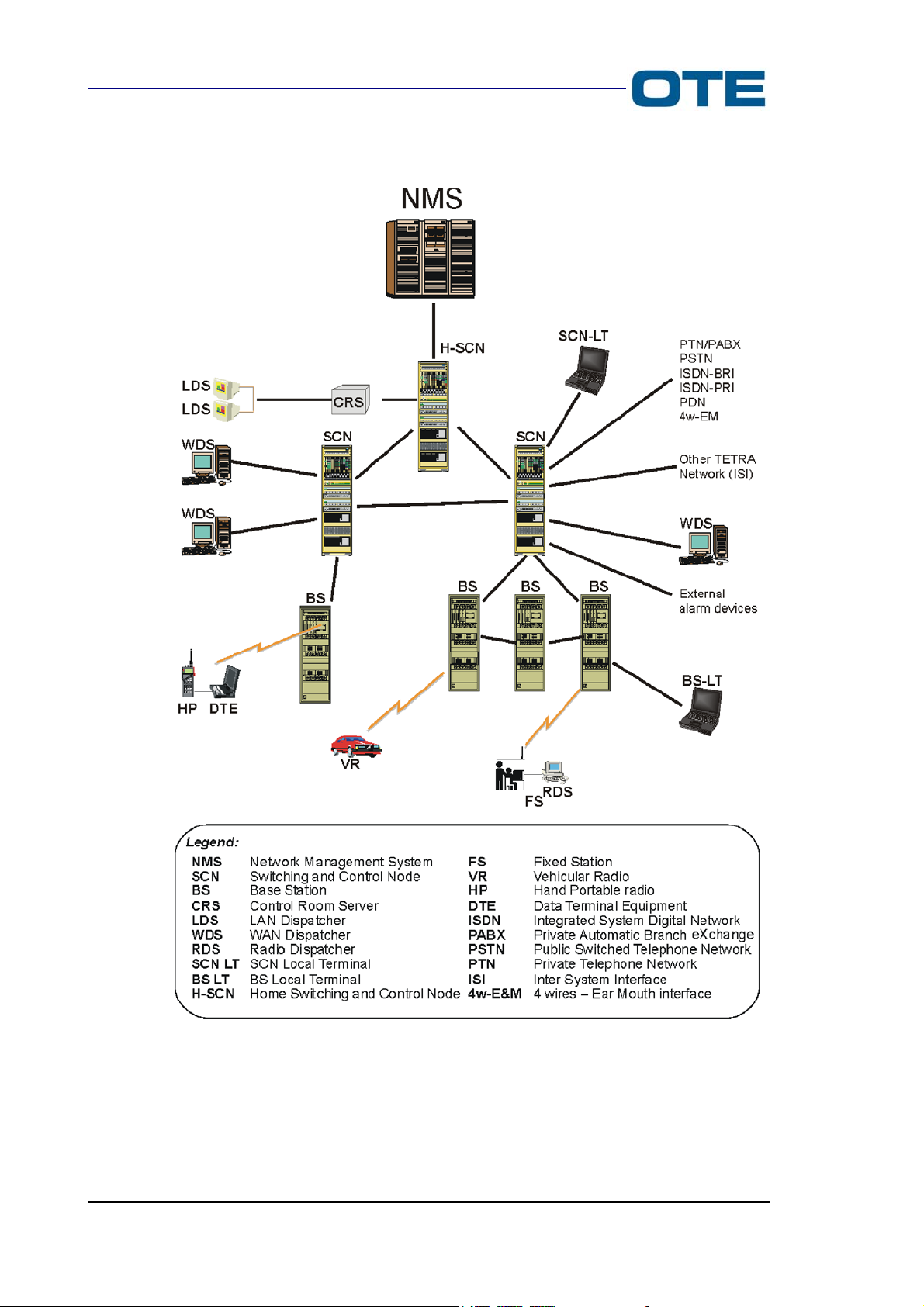
An example of a TETRA system architecture is shown in Fig. 1.1.
The main system elements are:
• Radio base stations (covering the whole network);
• Switching and control units;
• Network management system;
User terminals are divided in:
• Hand-held radio;
• Vehicular radio;
• Fixed station (desktop).
Page 2 Marconi Proprietary information
P/N: 779-0373/02
Revision 02

Tab. 1.1: Acronyms related to Fig. 1.1
4w-E&M
BS
BS LT
CRS
DTE
FS
HP
H-SCN
ISDN
ISI
LDS
NMS
PABX
PSTN
PTN
RDS
SCN
SCN LT
VR
WDS
4 wires – Ear Mouth interface
Base Station
BS Local Terminal
Control Room Server
Data Terminal Equipment
Fixed Station
Hand Portable radio
Home Switching and Control Node
Integrated System Digital Network
Inter System Interface
LAN Dispatcher
Network Management System
Private Automatic Branch exchange
Public Switched Telephone Network
Private Telephone Network
Radio Dispatcher
Switching and Control Node
Terminal
Vehicular Radio
WAN Dispatcher
VS 2001
Technical Handbook
Accessories
P/N: 779-0373/02
Revision 02
Marconi Proprietary information
Page 3
VS 2001
Technical Handbook
General Information
Fig. 1.1: TETRA Network Architecture
Page 4 Marconi Proprietary information
P/N: 779-0373/02
Revision 02

1.2.1 TETRA network equipment
In this paragraph the main characteristics of the TETRA radio communication
system are briefly described (see Fig. 1.1). Both the infrastructure and the
terminals are taken into consideration.
1.2.1.1 Radio Base Station (BS)
The Radio Base Station (BS) is a network element used to provide the
electromagnetic coverage of a certain cell and the radio connection with the user
terminals. Each base station is able to manage many RF carriers; each RF carrier
manages four channels.
The radiating system of the Radio Base Station is suitably configured depending
on the present requirements.
1.2.1.2 Switching and Control Node (SCN)
VS 2001
Technical Handbook
Accessories
Another element of the TETRA network is the Switching and Control Node (SCN).
The system switching capacity are mainly concentrated in the SCN, which controls
a certain number of Radio Base Stations, dispatch stations and even other SCNs.
Moreover, by using an ISI (Inter System Interface), the SCN can interface itself
with other TETRA networks and other external networks (e.g. ISDN, PSTN, PABX
etc..) through a gateway.
1.2.1.3 Network Management System (NMS)
The management of the TETRA network is accomplished by the NMS (Network
Management System) which is implemented on a single dedicated station. The
NMS can control a certain number of SCNs and can supervise the whole network
system.
1.2.1.4 Control Room Server (CRS)
The Control Room Server (CRS) constitutes the interface between the TETRA
system and the room operators. It manages a certain number of external working
stations connected, for example, through a LAN (Local Area Network).
1.2.1.5 WDS, RDS and LDS
There are different types of dispatch stations:
• WDS;
• RDS;
• LDS.
P/N: 779-0373/02
Revision 02
The WDS is managed by an operator with a fixed terminal; the connection to the
SCN is guaranteed by a WAN (Wide Area Network).
The RDS is the radio dispatch station and it is managed by an operator with a
terminal; this time the connection to the system is carried out via radio.
Marconi Proprietary information
Page 5

VS 2001
Technical Handbook
General Information
The LDS is directly controlled by the room server and its connection is
implemented through a LAN.
1.2.1.6 Terminals: fixed stations, vehicular and hand-held radios
Mobile stations are made up of vehicular and hand-held radio terminals. Both of
them can handle concurrent voice and data transmissions and they can
communicate each other relying on a base station or not.
Fixed stations are another kind of radio terminal with the same operative functions
of mobile stations, but they are generally installed inside a radio room.
1.2.2 Reference standard
The standards, adopted as reference in the implementation of TETRA radio
communication network, are the following:
• ETS 300 394-1
• EN 301 489-18
• ETS 300 392-2
• ETS 300 396-2
Page 6 Marconi Proprietary information
P/N: 779-0373/02
Revision 02
1.3 GENERAL CHARACTERISTICS
The VS 2001 equipment is a digital vehicular radio terminal designed in
compliance with the TETRA standard.
The equipment comprises two main modules: the Radio Unit transceiver and the
Front Panel.
The Radio Unit consists of a single piece, die-cast aluminium container that
contains the boards with the circuitry for signal processing both in transmission and
reception phase.
The Front Panel acts as an interface between the operator and the transceiver.
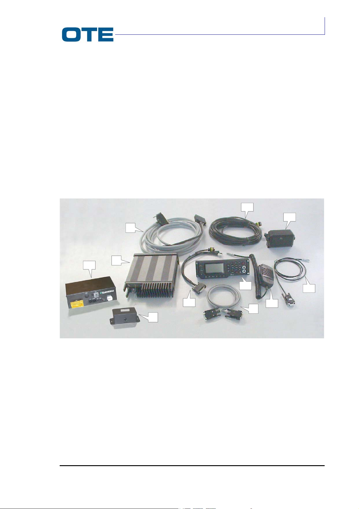
The VS 2001 equipment is shown in Fig. 1.2. The Front Panel is installed on the
dashboard. The transceiver is installed in the boot (trunk) of the vehicle, up to 6
metres from the Front Panel.
VS 2001
Technical Handbook
Accessories
3
4
2
10
1
7
9
6
5
8
11
1
VS 2001 radio unit
2
VS 2001 FPG1/A cable
3
Power supply cable
4
Loudspeaker
5
PC cable
6
Microphone
7
FPG1/A universal front panel
8
Rear PC cable (optional)
9
Loudspeaker and alarm cable
10
E-WHERE Module
11
E-WHERE / FPG1/A Interface
P/N: 779-0373/02
Revision 02
Fig. 1.2: VS 2001 equipment overview
Marconi Proprietary information
Page 7
VS 2001
Technical Handbook
General Information
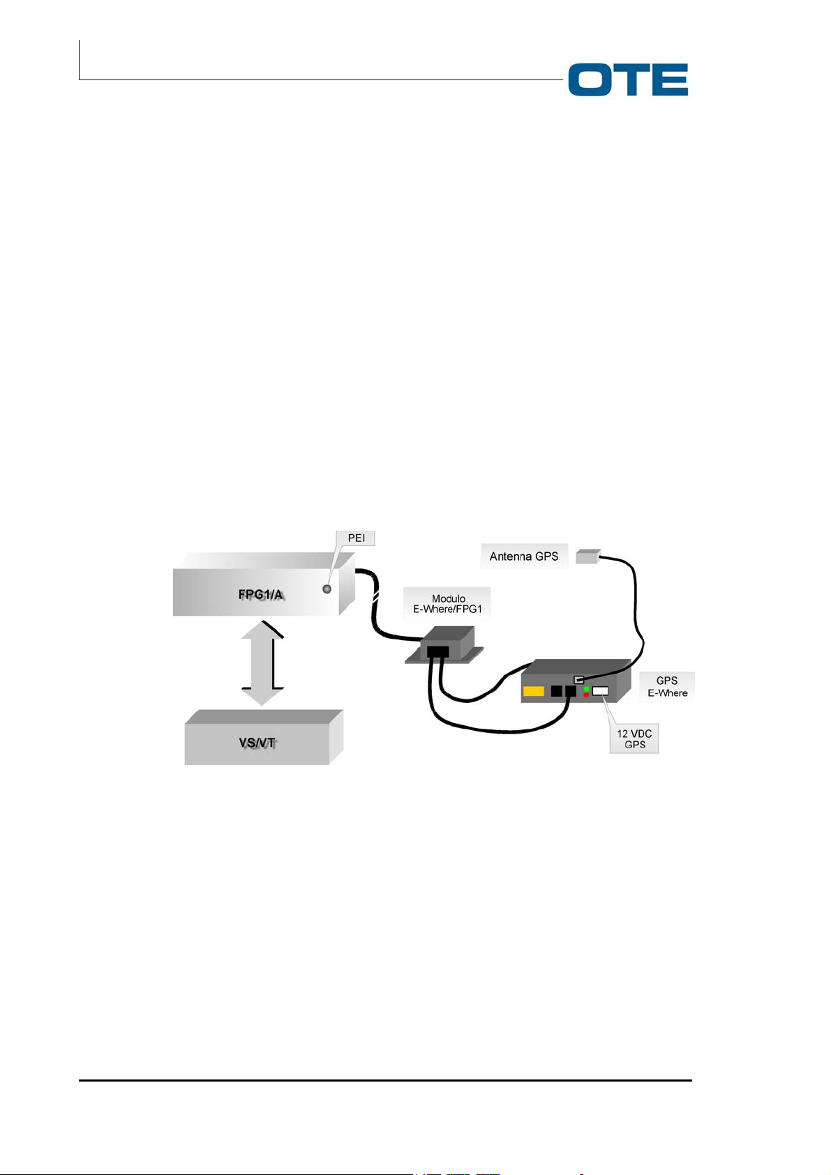
1.3.1 E-WHERE/FPG1/A Module
For the localization of the vehicle VT in which the VT equipment is installed we can
install also, the E-WHERE/FPG1/A interface.
The E-WHERE module (P/N 771-0940/01) is used in the vehicle configuration
equipped with a GPS E-WHERE module.
The equipment by means of the interfacing with FPG1/A, allows the use of
equipment like VT and VS (vehicle radio).
E-WHERE module make available the PEI serial line for a connection for PC on
FPG1/A; it avoid possible conflict with the GPS equipment that also used, of
default, the PEI serial line.
In the Fig. 1.3 the configuration is shown:
Fig. 1.3: E-WHERE/FPG1/A Module
Page 8 Marconi Proprietary information
P/N: 779-0373/02
Revision 02

1.4 NETWORK APPLICATION
The equipment can be used in the following operating modalities:
Trunked Mode
The Peripheral-Peripheral and Peripheral-Fixed connections take place through
the Network (Air Interface Protocol).
Call Control manages the activation, maintenance and release of voice/data calls
and is capable of managing up to four calls simultaneously.
The calls can be Individual or Group.
Direct Mode
The Peripheral-Peripheral connection takes place directly. In this case the
Peripheral-Network connection is not possible unless supported by Gateway which
constitutes the connecting element.
VS 2001
Technical Handbook
Accessories
Dual Watch Mode
The radio unit shall support Dual Watch Mode and than it is able of operating both
in Trunked and Direct mode although not simultaneously.
Dual Watch Mode enables the user to monitor the trunked mode control channel
while operating in Direct Mode and to monitor the channel in Direct Mode while
operating in Trunked Mode. This allows the user to switch from one operating
modality to another, but only when the radio is in IDLE status or when the call is
not active.
P/N: 779-0373/02
Revision 02
Marconi Proprietary information
Page 9

VS 2001
Technical Handbook
General Information
1.5 CHARACTERISTICS AND OPERATING FUNCTIONS
The main functions and services carried out by the VS 2001 equipment are:
• TETRA protocol management in radio environment with π/4 DQPSK
modulation (air interface levels 1, 2 and 3) in order to establish the connection
to the other TETRA radio connected to the network;
• Capability of managing both Half-Duplex and Full-Duplex (Time Division)
voice and data calls, via multi-access operation;
• Capability of operating in Direct Mode. In this operating modality the network
infrastructure is not used for communications between radios which must be
in direct radio coverage. In Direct Mode, the VS 2001 radio equipment
communicates directly with another radio unit by using a specific protocol. The
radio units must be tuned to the same frequency which is alternately used for
transmission and reception;
• Simultaneous voice and data transmission with multi-slot services
management capability. In particular, a high speed data transmission up to
28.8 kbit/s is allowed;
• Concurrent services management capability, as, for example:
- 1 slot for SDS (control channel) + 1 slot for voice call;
- 1 slot for voice call + 1 slot for data call.
• Operating services:
- Trunked Mode
- Half-Duplex Mode;
- Full-Duplex Mode (Time Division).
- Direct Mode:
- Half-Duplex Mode.
The operating modality selection is carried out by the user.
• Selection and sending of voice call, with the possibility of selecting the priority.
The voice calls may be Individual or Group type;
• Voice and data communications management with:
- Mobile radios;
- Dispatcher stations;
- Public or internal network telephone users.
• Transmission and reception of alphanumeric SDS messages (Short Data
Message) sent by the user by means of the radio equipment’s Front Panel;
• Data messages queue management;
• PEI management (Peripheral Equipment Interface), in compliance with the
TETRA ETS 300 392-5 standard;
Page 10 Marconi Proprietary information
P/N: 779-0373/02
Revision 02

VS 2001
Technical Handbook
Accessories
• Capability of managing and storing network users’ numbers;
• Capability of managing and storing pre-coded messages, such as emergency
messages, operating state messages, call reservation message;
• Alarm management;
• To allow connection to the external accessories;
• Alphanumeric keyboard management, with functional keys, a separate one of
which is dedicated to sending the emergency call;
• Management of the external accessories.
P/N: 779-0373/02
Revision 02
Marconi Proprietary information
Page 11

VS 2001
Technical Handbook
General Information
1.6 SERVICES
Operations whereby the equipment exchanges information with the Operating
Centre and/or with any other equipment registered under the system are
essentially the following:
• Transmission and reception of both full duplex and half duplex voice
• Transmission and reception of status messages;
• Transmission and reception of short data messages (SDS).
In particular, the equipment can carry out:
• Individual calls with the following types of signals:
communications;
- On/off hook: with acceptance accomplished by the radio terminal’s
operator,
- Direct set-up: with automatic acceptance.
• Individual half and full duplex voice calls between equipment-equipment,
equipment-dispatcher, equipment-gateway;
• Individual circuit Data Calls (single slots): 2.4 / 4.8 / 7.2 kbit/s half duplex;
• Circuit data transmission (multiple slot): up to 28.8 kbit/sec;
• Group voice calls;
• Joining a group call function;
• Short Data Service (SDS);
• Concurrent voice/data services;
• Priority calls;
• Priority calls with freeing up of resources;
• Late Entry: delayed entry of the radio terminal within an already active group;
• Calls authorised by the Dispatcher;
• Registration/de-registration.
Page 12 Marconi Proprietary information
P/N: 779-0373/02
Revision 02

1.7 PROGRAMMING THE EQUIPMENT
The equipment operating parameters are normally programmed with the auxiliary
of an external PC and a suitable programming kit (described in Section 4 of this
handbook), letting the user the possibility, however, of entering and/or modifying
some data by means of the Front Panel controls.
The configuration is accomplished by connecting the equipment to a personal
computer in order to carry out all of the configuration (individual and network data)
and personalisation operations.
For this purpose, a suitable software, the PRP (Programming Package) operating
on Windows 95/98/2000 NT platform has to be loaded in the personal computer
having a user friendly type of user interface with self explanatory windows. This
program allows the personalising of the various radio units and to carry out the
write, read, modify and print operations in the relative files.
In order to facilitate the above mentioned operations adequate aids are supplied
such as:
• Instruction manuals for programming and installing the software.
• "Help" on the display regarding the intervals relative to the parameters to be
set.
VS 2001
Technical Handbook
Accessories
It is also possible, through the same connection, to carry out the download of the
equipment’s operating software, thus allowing the upgrading of the software of the
equipment itself without having to tamper with the equipment in any way.
P/N: 779-0373/02
Revision 02
Marconi Proprietary information
Page 13

VS 2001
Technical Handbook
General Information
1.8 TECHNICAL CHARACTERISTICS
The VS 2001 equipment main technical characteristics are shown in Tab. 1.2.
Tab. 1.2: Technical characteristics
Parameters Type/Value
Dimensions
VS 2001 Radio Unit
202,4 x 186,4 x 58,4 mm
FPG1/A Control Panel 210 x 70,3 x 66,5 mm
Electrical characteristics
Air interface signalling EN 300-392-2
Power class 2 (10 W)
TX frequency band (Trunked Mode)
RX frequency band (Trunked Mode) VS 2001-400:
TX frequency band (Direct Mode) VS 2001-400:
VS 2001-400:
VS 2001-430:
VS 2001-470:
VS 2001-430:
VS 2001-470:
VS 2001-430:
VS 2001-470:
(380÷390) MHz
(410÷420) MHz
(450÷460) MHz
(390÷400) MHz
(420÷430) MHz
(460÷470) MHz
(380÷400) MHz
(410÷430) MHz
(450÷470) MHz or
(445,2÷445,3) MHz
RX frequency band (Direct Mode) VS 2001-400:
VS 2001-430:
VS 2001-470:
(380÷400) MHz
(410÷430) MHz
(450÷470) MHz or
(445,2÷445,3) MHz
Automatic power control Compliant EN 300 392-2
Carrier spacing 25 kHz
Receiver class EN 300 392-2 class A + B
RF architecture Half-duplex
Audio power 8 W, on 4 Ohm
Supply source Regulated Lead-Acid Battery
Nominal supply voltage Negative grounded: +13.8 VDC
Range: +10.8VDC to +15.6VDC
Power consumption (average on frame,
4 timeslots)
Stand by: < 1.3 A
Receiving mode: < 3 A
Transmitting mode: < 8 A
EMC specifications EN 301 489-18
Class EN 60950 class II
Installation category IEC 664 class I
Page 14 Marconi Proprietary information
P/N: 779-0373/02
Revision 02

Technical Handbook
Accessories
Tab. 1.2: Technical characteristics (Cont’d)
Parameters Type/Value
Environmental characteristics (Radio Unit module)
Operative temperature -20° to +55°C
Storage temperature -40° to +85°C
Relative humidity
10 to 95% at 50°C non condensing
Cold test ETS 300 019-1-5 class 5.2 (within the
operative temperature range)
Dry hot test
ETS 300 019-1-5 class 5.2 (within the
operative temperature range)
Air temperature change test ETS 300 019-1-5 class 5.2
Damp heat cyclic test
Protection to dust and water
Shock and vibrations
ETS 300 019-1-5 class 5.2
IP54
ETS 300 019 1-5 IEC class 5M3
VS 2001
Environmental characteristics (Front Panel module)
Operating temperature range -20 to + 60°C
Storage -40 to + 85°C
Relative humidity 10 to 95% at 55°C
Protection to dust IP54
Shock and vibrations ETS 300 019 1-5 IEC class 5M3
Transmitter characteristics
Modulation
π/4 DQPSK
Maximum power in antenna 10W (Tetra Power Class 2)
Power of undesired output in non active
transmission state
In compliance with EN 300 392-2
Adjacent channel power due to modulation In compliance with EN 300 392-2
Adjacent channel power due to commutation
transistors.
In compliance with EN 300 392-2
Undesired emissions far from the carrier In compliance with EN 300 392-2
Receiver characteristics
Sensitivity In compliance with EN 300 392-2
Rejection of co-channel In compliance with EN 300 392-2
Blocking characteristic In compliance with EN 300 392-2
Rejection of spurious response In compliance with EN 300 392-2
Rejection of inter-modulation response In compliance with EN 300 392-2
Conducted emission undesired In compliance with EN 300 392-2
Irradiated emission undesired In compliance with EN 300 392-2
P/N: 779-0373/02
Revision 02
Marconi Proprietary information
Page 15

VS 2001
Technical Handbook
General Information
1.9 MAIN COMPONENTS
The VS 2001 main components are listed in Tab. 1.3.
Tab. 1.3: VS 2001 main components
Description P/N
Main elemets
Radio unit
Control Panel (FPG1/A) 774-0376/01
Control remote assembly (for motorcycle
configuration)
Installation
Installation kit for control panel (in the car
radio cavity)
Installation kit for control panel
(adjustable bracket)
Installation kit for control panel (lite
bracket)
Installation kit for VS 2001 771-0734/01
Bracket to install the radio unit 971-0271/01
GPS/E-WHERE
GPS Antenna 978-0475/01
Kit E-WHERE/FPG1 + cables 771-0955/01
E-WHERE module 978-0472/01
Accessories
Antenna
Loudspeaker Vehicular: 774-0139/01
Microphone
Magnetic Hook Handset 978-0263/01
Mechanical Hook Handset (MAM2000,
for motorcycle configuration)
Documentation
User guide English version: 779-0217/03
Short user guide English version: 779-0218/03
Technical manual 779-0373/02
VS 2001-400:
774-0017/02
774-0017/03
VS 2001-430: 774-0312/01
774-0312/02
VS 2001-470: 774-0313/01
774-0405/02
771-0565/01
771-0566/01
771-1016/01
(400-430): 771-0249/01
(470): 771-0669/01
Motorcycle: 978-0477/01
Type MK1B: 978-0314/01
978-0571/01
Italian version: 779-0217/02
Italian version: 779-0218/02
Page 16 Marconi Proprietary information
P/N: 779-0373/02
Revision 02

1.10 SAFETY RECOMMENDATIONS
Carefully read all of the cautions and warnings before using the vehicular radio:
Do not use the radio equipment for uses different than those
indicated in the manual.
For a correct use of the radio equipment, read what is listed in the
user's guide.
VS 2001
Technical Handbook
Accessories
Protect the radio from sprinklings of water and/or other liquids and
from dust.
Be careful not to damage the vehicular radio when cleaning the
vehicle.
Do not use the vehicular radio if the antenna and/or the antenna cable
are damaged.
The electronic devices are sensitive to electromagnetic interference
(EMI) if not adequately shielded, designed or configured differently for
electromagnetic fields immunity.
If electromedical equipment (ex. pace-makers, acoustical equipment,
etc.) is used together with the vehicular radio, make sure that it is
adequately shielded from external electromagnetic fields.
P/N: 779-0373/02
Revision 02
Do not take the radio into environments that have a potentially
explosive atmosphere (ex. fuel storage sites, filling stations, etc.).
The E-WHERE is only suitable for vehicles with the negative pole of
the battery earthed to bodywork. Installation on other vehicles can
cause faults and damage/fire to cables.
Marconi Proprietary information
Page 17

VS 2001
Technical Handbook
General Information
Install the vehicular radio following the instructions given in this
manual. The equipment must be installed in such a way that it
complies with the national regulations in effect.
Carry out the maintenance interventions on the vehicular radio
following the instructions given in this manual.
Follow all accident prevention standards when carrying out
maintenance interventions on the vehicular equipment and use the
proper tools (spanners, screwdrivers,…..).
First and second maintenance level interventions, on the vehicular
radio are to be carried out by authorized technicians only.
Third maintenance level interventions are to be carried out by OTE
technicians only.
Use only original accessories and spare parts, approved by the
manufacturer, suitable for the vehicular radio. The use of different
accessories and/or spare parts makes the safety and electromagnetic
compatibility certifications to be valid no more and it could lower the
user safety level and/or generate electromagnetic fields that exceed
the accepted limits.
After the radio has been trasmitting for a long period, it may reach
high temperatures: in such a case avoid touching the radio shell.
The emergency call is a priority type call.
The vehicular radio, like all mobile telephony equipment, operates
with radio frequency signals, therefore, the forwarding of the call
depends on the network coverage at the moment of the call.
If you need send an emergency call, keep pressed the emergency
button for at least 2 seconds.
The radio complies with all product specifications and great care is taken by the
manufacturer so that user safety, as far as the effects of electromagnetic waves on
health are concerned, is guaranteed within the limits established by the
international specifications.
Page 18 Marconi Proprietary information
P/N: 779-0373/02
Revision 02

1.11 ESD PRECAUTIONS
No ESD precautions have to be taken by the operator. The VS 2001 vehicular
radio and its ancillary parts are designed and manufactured in such a way to not
be sensible to electrostatic discharges according to what referred in the EN 301
489-18.
VS 2001
Technical Handbook
Accessories
P/N: 779-0373/02
Revision 02
Marconi Proprietary information
Page 19

VS 2001
Technical Handbook
General Information
PAGE INTENTIONALLY LEFT BLANK
Page 20 Marconi Proprietary information
P/N: 779-0373/02
Revision 02

2. TECHNICAL DESCRIPTION
2.1 INTRODUCTION
This section contains the functional description of the VS 2001 vehicular
equipment in order to give the maintenance technician a good knowledge of the
equipment operating principles.
2.2 GENERAL DESCRIPTION
The VS 2001 equipment is made up of two main modules:
• VS 2001 Radio Unit;
• FPG1/A Universal Front Panel.
VS 2001
Technical Handbook
Accessories
The VS 2001 Radio Unit contains three different cards:
• Base Band card;
• R/T card;
• P.A. card.
The FPG1/A Front Panel provides the user with the interface controls, the audio
accessory connectors and an RS 232 serial line.
The VS 2001 equipment general configuration scheme is shown in Fig. 2.1.
2.2.1 VS 2001 connectors overview
In this paragraph the Radio Unit / Front Panel connector, the Front Panel and
Radio Unit external connectors are described (see Fig. 2.1).
Radio Unit / Front Panel connector
The connection between the Radio Unit (DB25 connector) and the Front Panel
(DB37 connector) provides RS232 serial line communication, low frequency audio
signal transfer and logic control signals (PTT, Emergency, etc.).
External connectors on the Front Panel
The J1 7-pin connector provides the connection of a microphone or an handset.
The J2 7-pin PEI connector provides the connection of an external PC for the
downloading of application software, setting-up of the operating parameters and
functional monitoring.
Both J1 and J2 connectors are placed on the front side of the FPG1/A.
P/N: 779-0373/02
Revision 02
Marconi Proprietary information
Page 21
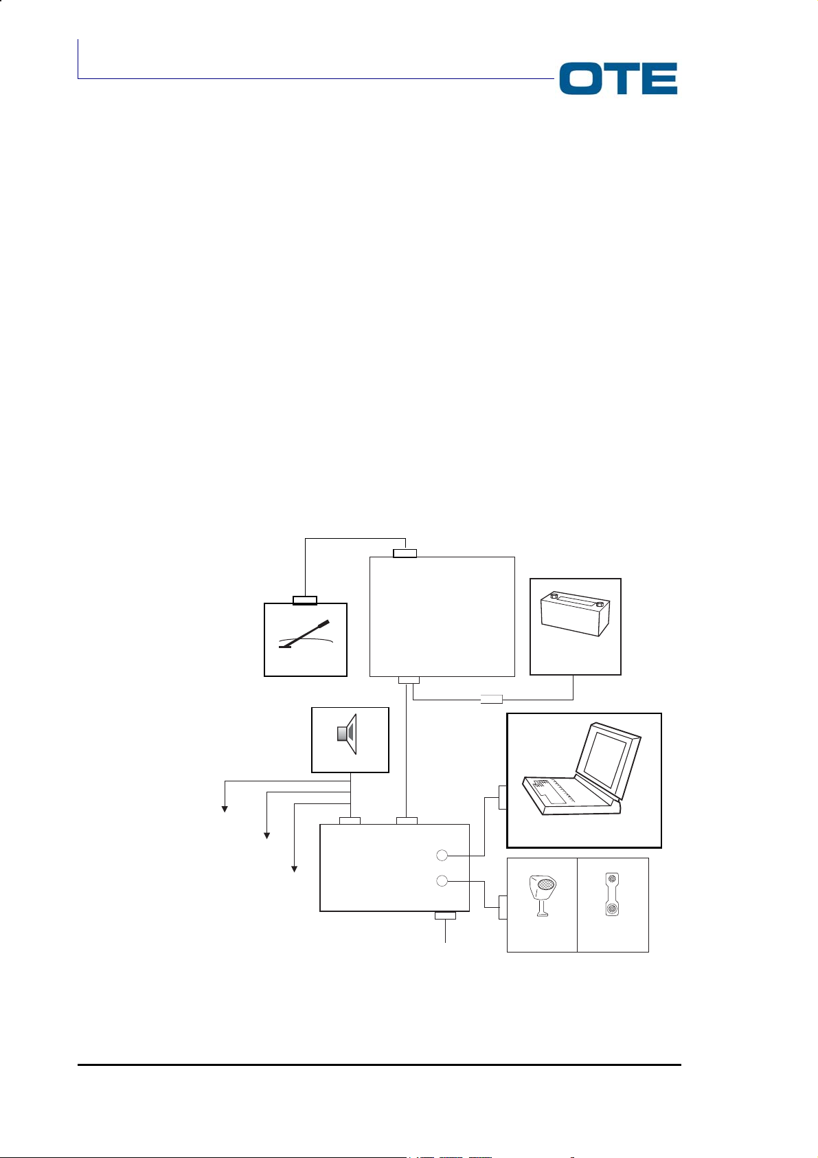
VS 2001
Technical Handbook
Technical Description
The DB15 connector provides the connection of a loudspeaker, an external
microphone, an external PTT and an external alarm.
The DB9 serial line PEI connector provides the connection of a PC for the
downloading of application software, setting-up of the operating parameters and
functional monitoring.
Both DB15 and DB9 connectors are placed on the rear side of the FPG1/A.
Radio Unit external connectors
There are two connectors on the rear side of the Radio Unit (heat sink side): a
BNC connector and a D type connector.
The J18 BNC connector provides the connection of the vehicular antenna.
The DB25 connector (P01) is a multifunction connector that includes:
• Power supply connector;
• Radio Unit / Front Panel connector;
• A main serial line (3-wire standard RS 232) to carry out a PEI connection with
a baud rate up to 115.2 kbit/s;
• An optional serial line (2-wire standard RS 232) with a baud rate up to 57.6
kbit/s.
MICROPHONE
EXT.
PTT
Antenna
ALARM
EXT.
Loudspeaker
DB15
FPG1/A
VS 2001
RADIO UNIT
DB25
DB37
J2 (PEI)
J1
DB9 (PEI)
FUSE 16A (6-25 mm)
JB
Microphone
Car Battery
PC
Handset
Fig. 2.1: VS 2001 configuration scheme
Page 22 Marconi Proprietary information
P/N: 779-0373/02
Revision 02
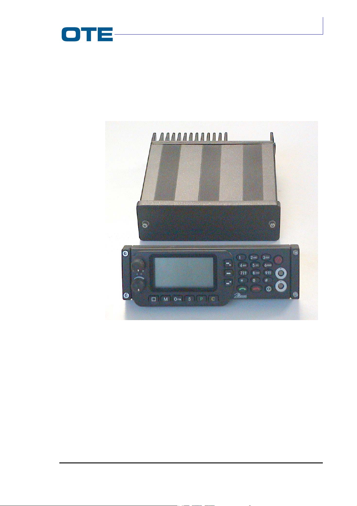
2.3 RADIO UNIT FUNCTIONAL DESCRIPTION
The Radio Unit module comprises a die-cast structure inserted in a metallic
container (tube) as shown in Fig. 2.2.
VS 2001
Technical Handbook
Accessories
P/N: 779-0373/02
Revision 02
Fig. 2.2: Equipment structure: Radio Unit and Front Panel modules
The rear side of the Radio Unit container is made up of a finned surface to
dissipate heat (heat-sink). The internal space of the Radio Unit container is divided
into three compartments: a large one, on one side and two smaller on the other
side.
The Radio Unit electronic circuits are distributed on three cards:
• Base Band card (housed in the large compartment);
• R/T card (housed in the small front compartment);
• P.A. card (housed in the small rear compartment in direct contact with the
heat sink).
Marconi Proprietary information
Page 23
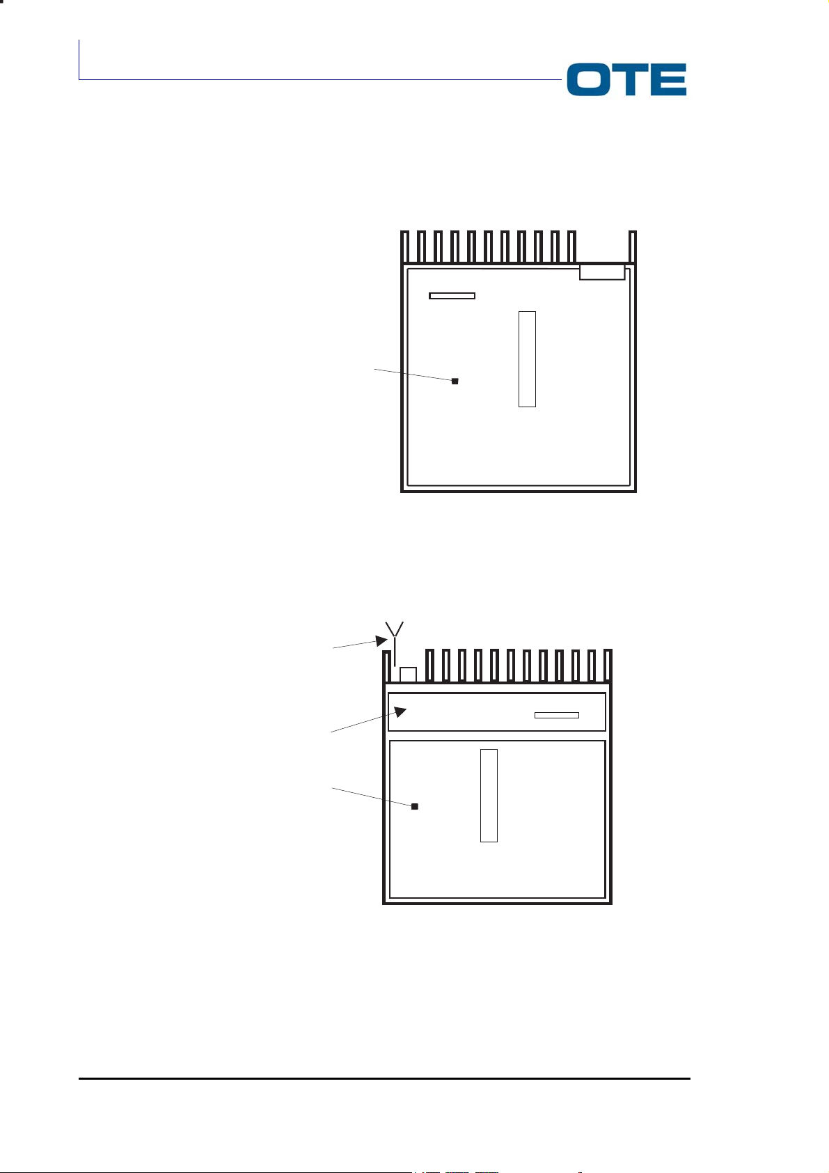
VS 2001
Technical Handbook
Technical Description
The Base Band card is housed on one side of the Radio Unit module, while the
other two cards on the reverse side (see Fig. 2.3 and Fig. 2.4).
P01
J04
BASEBAND CARD
J02
Fig. 2.3: View from the Base Band card side
ANTENNA
P.A. CARD
J18
J06
R/T CARD
Fig. 2.4: View from the R/T and P.A. cards side
Page 24 Marconi Proprietary information
J15
P/N: 779-0373/02
Revision 02
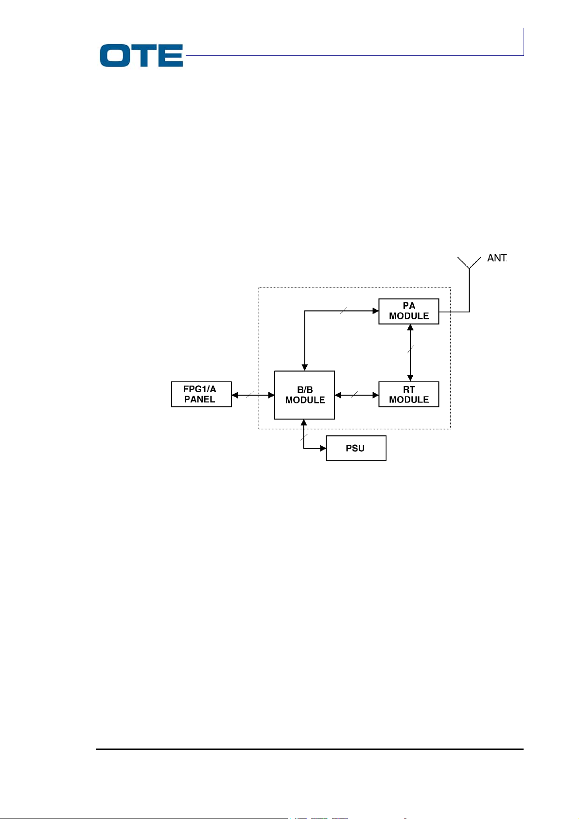
VS 2001
Technical Handbook
Accessories
The block diagram of the VS 2001 Radio Unit module is shown in Fig. 2.5. The
Base Band card processes the base band signal in both transmission and
reception phases. The R/T card translates the signal from audio frequency to radio
frequency (transmission phase) and viceversa (reception phase); it also preamplifies the signal. The P.A. card amplifies the transmitted signal to the required
power level.
The functional descriptions of the Base Band card, R/T card and P.A. card are
respectively reported in par. 2.3.1; 2.3.2 and 2.3.3.
Radio Unit
Module
2.3.1 Base Band card
Basically the Base Band card processes the signal in both transmission and
reception phases, thus it hosts the processing units such as DSP and
microprocessor.
The functional block diagram of the Base Band card is shown in Fig. 2.6.
Fig. 2.5: VS 2001 architecture overview
P/N: 779-0373/02
Revision 02
Marconi Proprietary information
Page 25
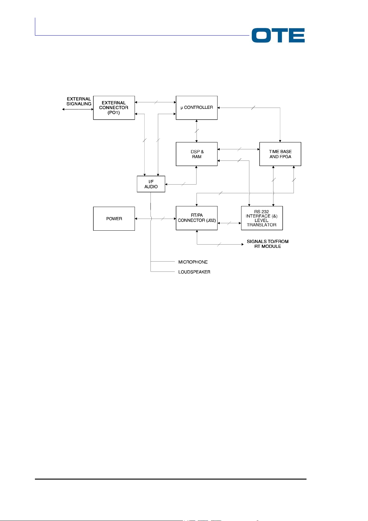
VS 2001
Technical Handbook
Technical Description
Fig. 2.6: Base Band functional block diagram
The Base Band card basically comprises the following functional blocks:
• I/F Audio;
• Microcontroller and Memories;
• DSP & RAM;
• Asic Time Base;
• RS232 interface & Level Translator circuit.
The card also contains:
• External connector;
• R/T and P.A. card interfacing connectors;
• Power Unit.
Page 26 Marconi Proprietary information
P/N: 779-0373/02
Revision 02

VS 2001
Technical Handbook
Accessories
The individual circuits of the Base Band section can be summarised as follows:
• A microcontroller that has the general control of all the radio activities. It is
supported by a RAM, a FLASH EPROM, 2 EEPROMs and an identification
code generator;
• Microcontroller interfaces to the FPGA and directly to the R/T card (this
section is included in the microprocessor block);
• A DSP (with its own RAM) which is interfaced to the A/D and D/A converters
of RX and TX and to the audio signals (from microphone/handset and to
loudspeaker/headset) through the CODEC;
• An FPGA which acts as a control interface for the R/T card and as an
interface between the DSP and the A/D and D/A converters of the R/T
section. The FPGA also generates all the timing signals. All the timing signals
are derived from a reference clock, set at Fref (see Tab. 2.5), and generated
by an appropriate circuitry.
Since some parts of the Base Band card are powered at 5 V and some others at
3.3 V, there is a level Translator circuit in order to connect them.
Other electronic devices contained on this card are listed as follows:
• Protection diode against power supply polarity inversion;
• LC filtering of battery power supply;
• Main FET switch which interrupts power supply to all equipment circuits;
• Audio power amplifier to drive the loudspeaker;
• Stabiliser generating a voltage of +7.2 V used by the R/T card;
• Stabiliser generating a voltage of +5 V used by the Base Band card;
• Stabiliser generating a voltage of +3.3 V used by the Base Band card;
• Stabiliser generating a voltage of +5 V (+5VTLC) used by the Front Panel.
Connection to the R/T card is carried out via the J02 double 36-pin connector (see
2.3.1.2).
Connection with the P.A. card is carried out via the J04 6-pin single comb male
connector (see 2.3.1.2).
2.3.1.1 External connector
The P01 external connector (25-pin male D-type connector) provides the physical
interface between the Base Band card and the external accessories.
The signals, exchanged via this interface, are:
• User commands (i.e. terminal turning on command, Push-To-Talk (PTT)
command, alarm command)
• Data with terminal on asynchronous serial line with the possibility of using the
RTS and CTS control signals. The baud rate can be selected at 110, 300,
600, 1200, 2400, 4800, 9600, 14400, 19200, 28800, 38400, 57600 and
115200 bps;
• Data with terminal on a second asynchronous serial line. The baud rate can
be selected at 9600, 19200, 38400 and 57600 bps;
P/N: 779-0373/02
Revision 02
Marconi Proprietary information
Page 27
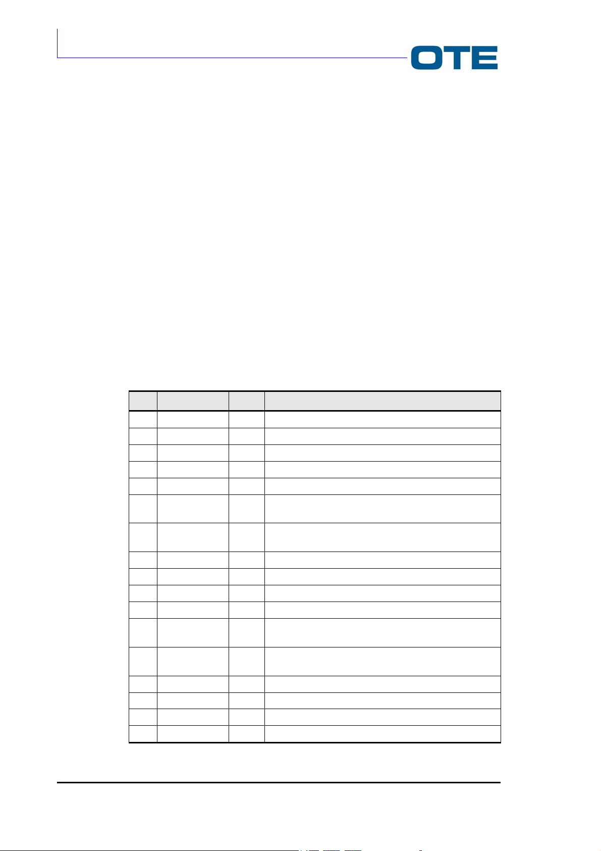
VS 2001
Technical Handbook
Technical Description
• Audio signal coming from microphone/handset;
• Audio signal to loudspeaker/headset;
• Power supply voltage provided by the vehicular battery;
• Control signals for external accessories.
The connection is carried out through the 25-pin male D-type connector (P01).
2.3.1.2 Base Band card interfacing
The physical interface between the Base Band card and the analogue part of the
vehicle equipment (R/T and P.A. cards) is carried out via two connectors:
• J02 (36-pin female connector) with relative filter capacitors. It constitutes the
interface with the low power analogue part (R/T card);
• J04 (6-pin female connector) with relative filter capacitors. It constitutes the
interface with the power transmission analogue part (P.A. card);
The allocation of the interface signals on these connectors and their meaning are
described in Tab. 2.1 and Tab. 2.2.
Tab. 2.1: J02 connector description
Pin Name Type Description
1 7.2 V PWR Analogue card power supply voltage
2 GND PWR Ground line
3 GND PWR Ground line
4 CK2304DA OUT Data synchronisation signal for Tx “air”
5 LATCH OUT Word synchronisation signal for Tx “air”
6 ITXD OUT Line for digital data relative to channel I of Tx for DAC
1866
7 QTXD OUT Line for digital data relative to channel Q of Tx for DAC
1866
8 SD OUT Shut down signal towards RT
9 TXON OUT O.C. control signal for transmission circuits on RT
10 PAON OUT O.C. control signal for transmission circuits on RT
11 SERDATAIN IN EEPROM reading serial line data on radio card
12 HCKSER OUT Clock synchronous serial line for 3 DAC quad, SINT and
EEPROM
13 HDATASER OUT Data synchronous serial line for 3 DAC quad, SYNTH
and EEPROM
14 HENDAC OUT Enabling signal for 3 DAC quad
15 HENEEPROM OUT Enabling signal for EEPROM present on RT card
16 HENSINT OUT Enabling signal for SINT present on RT card
17 GND PWR Ground line
Page 28 Marconi Proprietary information
P/N: 779-0373/02
Revision 02
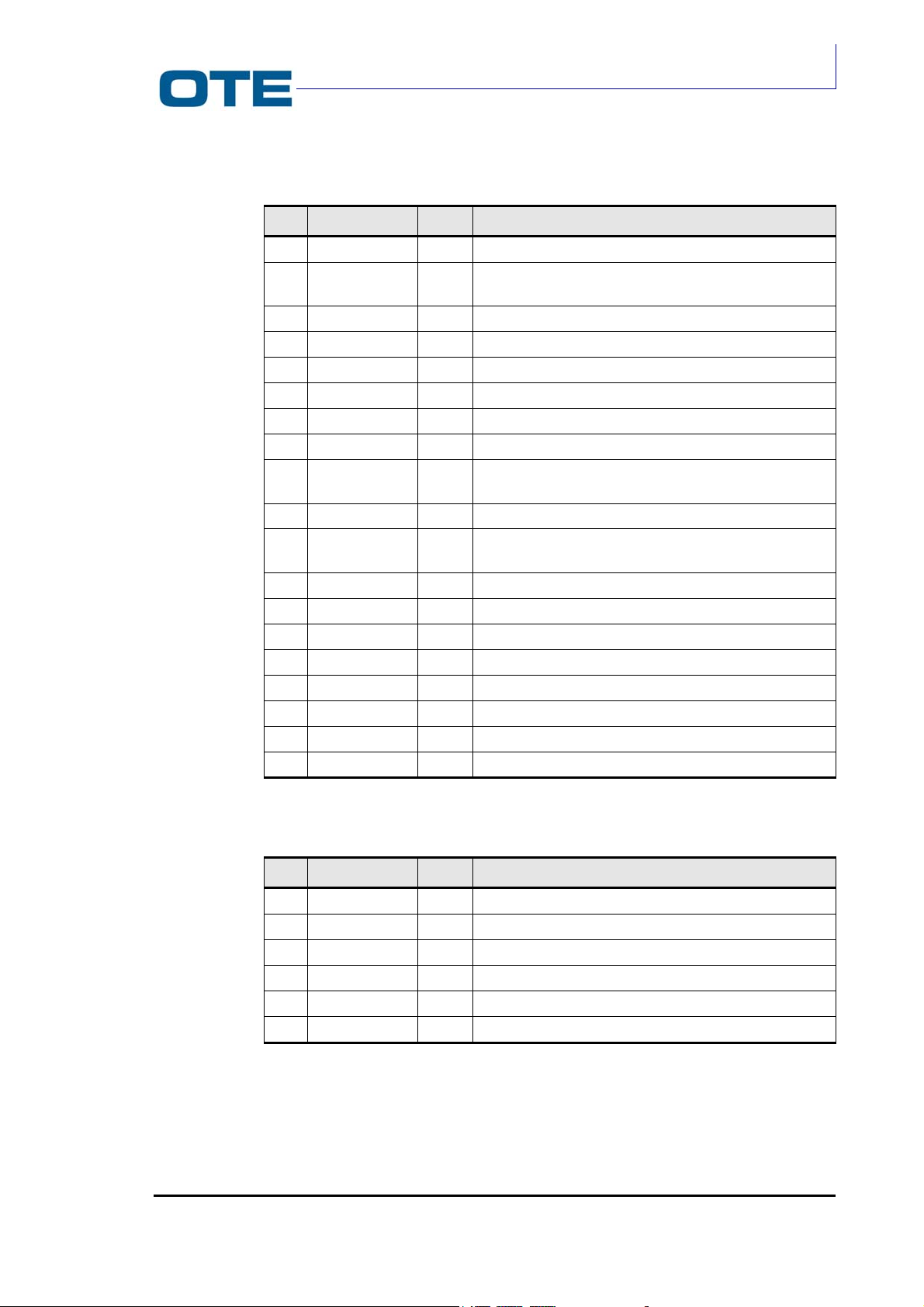
VS 2001
Technical Handbook
Accessories
Tab. 2.1: J02 connector description (Cont’d)
Pin Name Type Description
18 GND PWR Ground line
19 Fref
IN
Reference frequency 12.8 MHz from R/T card to Base
Band
20 GND PWR Ground line
21 BSW OUT O.C. signal for setting operating frequency band
22 LD IN Signal for verification of correct operation of the SYNTH
23 GND PWR Ground line
24 HFRAMEAD OUT Frame synchronisation signal for control data AD7013
25 HDATAAD OUT Control data for AD7013
26 HCK2304AD IN Clock timing signal for data on synchronous control
serial line AD7013
27 HCK4608 OUT Master clock for AD7013
28 HFLAGIQ IN Frame timing signal for serial line data relative to
channels I and Q in reception
29 HIQRXAD IN Serial line relative to channels I and Q in reception
30 RXON OUT O.C. control signal for reception circuits on RT
31 GND PWR Ground line
32 GND
PWR Ground line
33 GND PWR Ground line
34 GND PWR Ground line
35 GND PWR Ground line
36 7.2 V PWR Analogue card power supply voltage
P/N: 779-0373/02
Revision 02
Tab. 2.2: J04 connector description
Pin Name Type Description
1 VBATTINT PWR PA RF power supply voltage
2 VBATTINT PWR PA RF power supply voltage
3 GND PWR Ground line
4 GND PWR Ground line
5 VSWR IN VSWR signal
6 PAON OUT O.C. control signal for transmission circuits on PA RF
Marconi Proprietary information
Page 29

VS 2001
Technical Handbook
Technical Description
2.3.1.3 Level Translator
The level Translator is the interface for the 3.3 V signals generated on the Base
Band card and addressed to the 5 V CMOS devices located on the R/T card.
Such signals are the following:
• Signals connected to R/T card and generated by the Time Base unit. Their
voltage level is translated from 3.3 V to 5 V.
• Signals of the serial synchronous interface and signals necessary for the DAC
programming. Their level is translated from 3.3 V to 5 V.
• Configuration signals (R/T and P.A. cards) for the transmission and reception
processes. The above mentioned signals are generated by the Time Base
and then converted from 3.3 V to 5 V.
2.3.1.4 Power Unit
This unit provides the power supply voltages for the Base Band card, the R/T card,
the P.A. card and the connected peripherals. The power supply voltages provided
by the power unit are derived from the vehicular battery.
The following power supply voltages are available:
• VBATT+: general power supply voltage provided by vehicular battery (12 V
nominal);
• VBATTINT: general power supply voltage interrupted by dual MOSFET (12 V
nominal less losses on MOSFET and protection circuitry);
• +8 V: power supply voltage dedicated to R/T card (7.2 V nominal);
• VMASTER: power supply voltage adjusted to approx. 6.5 V;
• 12 VTLC: power supply voltage dedicated to the remote control;
• VD5: 5 V for 5 V digital circuitry;
• VCC: 3.3 V for 3.3 V digital logic;
• VA3: 3.3 V for 3.3 V analogue circuitry;
• VC2: 2.5 V for DSP core.
2.3.1.5 I/F Audio
This unit provides the interface between the external audio devices (loudspeaker/
headset and microphone/handset) and the Digital Signal Processor device (DSP),
both in transmission phase (towards the loudspeaker/headset) and in reception
phase (from the microphone/handset).
The input main/rear microphone signal is approx. 200 mVrms. The Audio interface
provides the signal voltage level (2.5 Vpp) required by the CODEC voice
digitalisation device that samples the signal at 8 kHz on 13 significant bits. It
supplies the digitised value to the DSP on a dedicated DXS synchronous serial
line, with timings generated by the Time Base unit.
Page 30 Marconi Proprietary information
P/N: 779-0373/02
Revision 02

In the transmission phase the DSP generates the voice samples at 8 kHz towards
the CODEC; the samples are digitised on 13 significant bits and transmitted on a
dedicated DRS synchronous serial line with timings generated by the Time Base.
The CODEC reconstructs the audio analogue signal and supplies it to the audio
amplifier which reconditions it in power (8W max. in 4 Ohm, 125 mW max. in 25
Ohm) as a function of the signals coming from the micro.
The I/F AUDIO block is controlled in stand-by by the microcontroller.
2.3.1.6 Microcontroller
The microcontroller manages all the network digital processes and the internal
activities of the VS 2001 equipment. The processes managed by the
microcontroller may be resumed as follows:
• TETRA protocol management from the Upper MAC sub-level up to the
Mobility Management and Call Control upper levels;
• Co-management with control unit present on management terminal of the MMI
functions (in this configuration the user commands, keyboard and display are
located on peripherals connected to the Base Band through connector J02
and connector P01);
• DTE management;
• Interface management towards the Firmware of Lower MAC resident on DSP;
• Terminal identification management;
• Management of the DSP operating programs download;
• Management of the R/T and P.A. analogue cards functioning.
VS 2001
Technical Handbook
Accessories
The microcontroller is also able to manage other functions by means of the
following devices:
• 1 asynchronous communication UART dedicated to peripheral DTE. The data
communication lines for reception and transmission operate in full-duplex
modality. The serial line is programmable with variable baud rates: 110, 300,
600, 1200, 2400, 9600, 14400, 19200, 28800, 38400, 57600 and 115200 with
1 start bit. This serial line is accessible through the rear connector P01. The
electrical levels of the signals are in compliance with standard RS232;
• 1 asynchronous communication UART of full-duplex type dedicated to the
connection with the management terminal for MMI functions control. This
serial line can be used, alternatively, for data exchange with peripheral DTE.
The serial line is programmable with baud rates of: 110, 300, 600, 1200, 2400,
9600, 14400, 19200, 28800, 38400, 57600 and 115200 with 1 start bit, 1 or 2
stop bits and possibly 1 parity check bit. This serial line is accessible through
the front connector J1. The electrical levels of the signals are in compliance
with standard RS232;
• The micro controls a third asynchronous serial line integrated on Asic Time
Base. This serial line consists of two data communication lines for reception
and transmission in full duplex and is accessible through rear connector P01.
The electrical levels of the signals are in compliance with standard RS232;
P/N: 779-0373/02
Revision 02
Marconi Proprietary information
Page 31

VS 2001
Technical Handbook
Technical Description
• 1 synchronous communication serial line towards EEPROMS and FPGA;
• 3 A/D converter (10 bit) with 3 active channels multiplexed for the VSWR
measurement (i.e. temperature);
• 1 watchdog;
• 25 independent I/O ports at 1 bit each;
• 1 FLASH memory (1 Mword) for storing both the microprocessor and the DSP
application software. The microcontroller software can be applied directly by
the flash without time penalties;
• 1 SRAM memory (256 kword);
• Device for terminal identification through 48 bit individual code;
• Non-volatile read/write memory for storing some semi-permanent network
data;
• Non-volatile read/write memory protected by password for storing the Air
Interface Encryption keys.
2.3.1.7 DSP
Basically the DSP (Digital Signal Processor) is used for the execution of following
procedures:
• Physical layer numerical processing algorithms both in uplink (transmission)
and in downlink (reception);
• Management of the TETRA protocol relative to the Lower MAC sub-level;
• Management of the interface towards/from I/F AUDIO for the digitised voice
signal;
• Management of the serial interface towards/from I/F RT for the TETRA
modulated base band signal;
• Management of the asynchronous serial line integrated on FPGA and
dedicated to the DSP.
The DSP also hosts the following devices and interfaces:
• 2 independent and buffered bi-directional synchronous serial lines; one for
interfacing with the audio section and the other one with the radio section;
• 1 Host Port Interface with Dual Port RAM (2 kword) for communication with
the microprocessor;
• 1 standard JTAG interface for communication with external emulator;
• Digital PLL for Fck clock frequency generation (see Tab. 2.3) derived from the
Fmck master clock frequency (see Tab. 2.3);
• 32 kword of internal RAM for execution of the critical routines from the point of
view of the speed of execution and storing of frequently used data;
• 64 kword of external RAM, of which 3.2 kword reserved for the data and 32
kword reserved for the programs. The DSP automatically selects the
necessary area;
Page 32 Marconi Proprietary information
P/N: 779-0373/02
Revision 02

• 1 bi-directional synchronous serial line and an interrupt input dedicated to
management of the asynchronous serial line integrated on FPGA.
2.3.1.8 ASIC Time Base and PLL
Basically, the two blocks (Asic Time Base and PLL) carry out the following
functions:
• Generation of Fmck derived from Fref (see Tab. 2.3) coming from the R/T
card;
• Generation of the timings related to the radio frame;
• Generation of the timings related to the voice fame;
• Adaptation of the data serial flows relative to the quantized samples of the
base band signal in downlink between DSP block and R/T card;
• Adaptation of the data serial flows relative to the quantized samples of the
base band signal in downlink between DSP block and R/T card;
• Generation of the selections for the microprocessor external RAM;
• Integration of the microprocessor I/O ports relative to the radio activity control
of the R/T and P.A. cards and of the Base Band card;
• Integration of the interface for the synchronous serial line relative to control of
EEPROM, SINT and DAC present on the R/T card;
• Integration of the interface for the synchronous control serial line of the block
RT I/F;
• Selection of the micro bootstrap mode at reset;
• Generation of the clock for the time base of the asynchronous serial lines
(baud rates of 38400 and 115200) integrated on the micro;
• Integration of a two-way full-duplex UART (transmission and reception line)
with restricted set of baud rates. The serial line is controlled by the micro
through data bus, address bus and interrupt and it is available on rear
connector P01;
• Master Reset input for register blocks and internal counter;
• Generic output ports usable only for tests.
VS 2001
Technical Handbook
Accessories
P/N: 779-0373/02
Revision 02
For the integration of the I/O, UART and peripheral selection functions, the block
interfaces with the microprocessor via an address bus and four selection and
control lines.
Tab. 2.3: Base Band frequencies
Version Fref Fck Fmck
VS 2001-400 12.8 MHz 98.304 MHz 9.830 MHz
VS 2001-430 12.8 MHz 98.304 MHz 9.830 MHz
VS 2001-470 12.8 MHz 98.304 MHz 9.830 MHz
Marconi Proprietary information
Page 33

VS 2001
Technical Handbook
Technical Description
2.3.2 R/T card
The R/T card interfaces to the Base Band card through the J15 connector and to
the P.A. card through the radio frequency MCX J11, J12 and J13 connectors. The
circuits that make up the R/T card are divided into functional subassemblies
contained in a metallic structure that is divided into sectors.
The R/T card printed circuit has its components distributed on a single side and it
is made up of eight layers.
The printed circuit’s surface is sectioned into seventeen blocks separated by a
gold-plated copper strip discharged by the solder.
The arrangement of the R/T card sectors is shown in Fig. 2.7.
P.A.
J13
F.E.
+
MIXER RX
IF STAGE
VCO
100 MHZ
SD2
PLL 10 MHZ
LF FILTERS
AD7013
AD607
DUAL PLL
TCXO
SD1
C
O
N
N
E
C
T
O
R
VCO W.B.
470-530 MHZ
SD3
DAC AD1866
FILTRI BF TX
TRASLAT.IOB/QOB
SERVICES
DC/DC CONVERTER
(-5V)
DAC MAX525
SPLITTER
DRIVERS
LO1RX
MAV-11
TUNABLE
MIXER
TX
CELLS
J12
DEMODUL.
I/Q
SPLITTER
TX
TUN.
CELLS
TX
J11
MODUL.
I/Q
PHASE
SHIFTER
+
SHIFTER
VIB/VIQ
Fig. 2.7: R/T card: arrangement of the sectors
Page 34 Marconi Proprietary information
P/N: 779-0373/02
Revision 02

VS 2001
Technical Handbook
Accessories
The equipment operates in Trunking Mode with zero switching time (Rx / Tx) within
the same frame, i.e. the equipment receives and transmits on adjacent slots.
• The R/T card contains the circuits listed below:
• Tuneable RF head and mixer for the first frequency conversion;
• First intermediate frequency with quartz filter;
• Second intermediate filter and low frequency;
• Circuits for base band reception, service circuits and interface circuits with the
Base Band card inherent in the reception section;
• Frequency synthesiser (a second synthesiser is been added);
• Power supply circuits (DC/DC converter), service circuits and interface circuits
with the Base Band card inherent in the transmission section;
• TX mixer. Tuneable filter and first amplifier;
• Second tuneable filter and second amplifier;
• Third amplifier and power reducer;
• Phase-shifter circuits to generate the modulating components;
• Transmission modulator;
• Demodulation circuits for the RF signal and feedback circuits for phase
correction.
The block diagram of the R/T card RF section is shown in Fig. 2.8.
PA
MODULE
ANTENNA
SW
F
TX
TX
LO
TX
SYNTH
TX/RX
LO
RX
F
RX
RX
P/N: 779-0373/02
Revision 02
Fig. 2.8: RF section functional block diagram
Marconi Proprietary information
Page 35

VS 2001
Technical Handbook
Technical Description
The radio has a single synthesiser. This simultaneously produces the local
oscillators for both RX and TX in such a way that the reception of a RX frequency
can take place at the same time as the transmission of a TX frequency spaced
from the RX frequency by a 10 MHz duplex step. In this way the radio switches
from the reception on a downlink slot to the transmission on an uplink slot on the
same physical TETRA channel (and vice versa) in zero time. Obviously, when the
radio is allocated by the network to a physical channel of another TETRA radio
channel, the radio requires a switching time (typically less than 7 ms in a 10 MHz
band) in order to switch the radio to the new pair of uplink and downlink
frequencies. Note that the radio, not having a duplexer nor the necessary
insulation between RX and TX, cannot receive and transmit simultaneously and
thus remains of the half-duplex frequency type.
2.3.2.1 Functional description
The block diagram of the R/T card is shown in Fig. 2.9. The description of the
individual blocks that made up this card, is given below.
The received signal enters the R/T card through the J13 connector and than it is
sent to the front-end stage.
The front-end stage complies with the normal criteria for conventional tuneable
receivers. Frequency selectivity is provided by a tuneable π LC cell that is placed
before the active element (BJT) and by another two analogous cells after the same
BJT.
These three cells, which use Varicaps, are tuned through VT1, VT2 and VT3
voltage signals generated by a series of 12 bit DACs.
The total gain is G = 11 ± 1 dB in the centre of the band and its variation within the
band is ± 1.5 dB.
The front-end output is connected to a mixer together with the signal coming from
the VCO (SD3) local oscillator to carry out the first IF (Intermediate Frequency)
conversion at Fif1 (see Tab. 2.4).
Note that in reception a 3-conversion scheme has been adopted. The SD3 local
oscillator, set at Flo1 (see Tab. 2.4), is a VCO (Voltage Controlled Oscillator) is
controlled by the Dual PLL SA7025 (see Fig. 2.9). The signal supplied by the VCO
SD3 is obtained from the Temperature Compensated Oscillator (TCXO) SD1 (see
Fig. 2.9).
Page 36 Marconi Proprietary information
P/N: 779-0373/02
Revision 02

VS 2001
Technical Handbook
Accessories
REGULATED
VOLTAGE
SERIAL LINE
SERIAL LINE
LP
SERIAL LINE
FILTERS
LP
FILTER
VOLTAGE
TX TUN.
SHIFTER
SERIAL LINE
CELLS /
DRIVERS
SHIFTER
TX LP
FILTER
VOLTAGE
SHIFTER
IF BLOCK
QUARTZ
FILTER
P/N: 779-0373/02
Revision 02
Fig. 2.9: R/T card block diagram
Marconi Proprietary information
Page 37

VS 2001
Technical Handbook
Technical Description
Note that in Trunking Mode, the SD3 oscillator will be at the frequency necessary
to generate the TX carrier (in Trunking Mode the operating transmitted frequency is
10 MHz down translated respect to the reception frequency). This enables a
common SD3 in the RX/TX paths.
After the first conversion, the received signal is passed to the first intermediate
frequency block (IF block) where it is firstly amplified, than filtered and finally
amplified again. Successively the received signal enters the AD607 component,
where a second frequency conversion from Fif1 to Fif2 takes place (see Tab. 2.4).
For this operation the local oscillator is the same VCO SD2 (set at Flo2) used for
TX carrier generation (see Fig. 2.9 and Tab. 2.4).
Finally the last conversion from Fif2 to I and Q base band components is carried
out in the I/Q Demodulator block with PLL frequency set at Flo3 (see Tab. 2.4).
The TX carrier (obtained by means of the mixer that combines SD2 and SD3
signals) is filtered by a group of four tuneable π LC cells (controlled by VT4 to VT7
signals) in order to filter out the undesired products of the mixer before being
amplified. The Tx carrier is then divided into two separate paths through the
Splitter. One part is sent to the Cartesian Loop passive I/Q Demodulator, which
serves to linearize the P.A. signal and the other to the phase shifter realised by
using a passive I/Q Modulator. The phase displacement introduced by this block is
a function of the VIB and VQB control voltages and determines the Loop stability.
The phase shifter output is sent to the I/Q Modulator. The low frequency
components at the input of this modulator are the results of a summing block
(closing of the Loop and the direct line feedback) dependent on the ITX and QTX
components. These are generated by the DAC TX AD1866, by the TX feedback
loop demodulated signals and by the IOB and QOB controls for residual carrier
rejection.
The AD1866 receives, through the J15 connector, I and Q components for serial
lines transmission and generates ITX and QTX low frequency components for the
modulator.
The modulator output is amplified and then passed to the P.A. card input through
the J11 coaxial connector. The blip from the P.A. directional coupler (feedback
loop input) enters the vehicle R/T card through the J12 coaxial connector.
Tab. 2.4: R/T frequencies
Version Flo1 (SD3) Flo2 (SD2) Flo3 (PLL) Fif1 Fif2
VS 2001-400 (470 ÷ 500 ) MHz 100 MHz 10 MHz 90 MHz 10 MHz
VS 2001-430 (500 ÷ 530 ) MHz 100 MHz 10 MHz 90 MHz 10 MHz
VS 2001-470 (535.2 ÷ 570 ) MHz 100 MHz 10 MHz 90 MHz 10 MHz
Page 38 Marconi Proprietary information
P/N: 779-0373/02
Revision 02
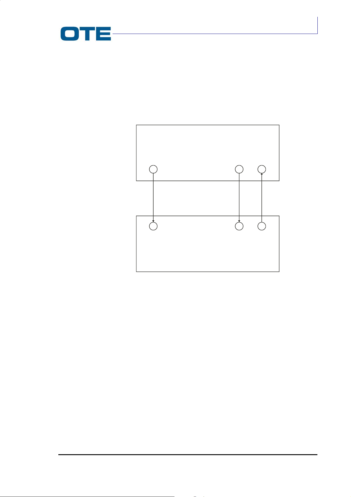
2.3.2.2 R/T card interfacing
The interfacing between R/T and P.A. cards and between R/T and Base Band
cards is here described.
There are three connections between R/T and P.A. cards which are realised
through “MCX” type connectors. These connections are shown in Fig. 2.10.
VS 2001
Technical Handbook
Accessories
P.A. CARD
J15 J16
J13
R/T CARD
Fig. 2.10: Connections between R/T and P.A. cards
The J11 connector is an output for the R/T card and is the Cartesian Loop direct
line. This connection terminates on the J14 connector of the P.A. card.
The J12 connector is an input to the R/T card and is the Cartesian Loop feedback.
This connection comes from the J16 connector of the P.A. card.
The J13 connector is the RX chain’s input and comes from the J15 connector of
the P.A. card.
The interfacing between R/T and Base Band cards is carried out through a 36-pin
connector. This connection takes place with dual strips which are inserted between
the two cards.
The cards’ connectors are both female.
The connection between R/T and Base Band cards is shown in Fig. 2.11.
J12
J14
J11
P/N: 779-0373/02
Revision 02
Marconi Proprietary information
Page 39

VS 2001
V
Q
D
Technical Handbook
Technical Description
BASEBAND CARD
J02 CONNECTOR
36
J15 CONNECTOR
R/T CARD
Fig. 2.11: Connection between R/T card and Base Band card
In Fig. 2.12 the J02 connector pin allocation is shown. Note that the J15 connector
on the R/T card is the mirror image of the J02 connector on the Base Band card.
+8
GND
GND
GND
GND
GND
RXON
HIQRXAD
HFLGI
HCK4608
HCK2304A
HDATAAD
HFRAMEAD
GND
LD
BSW
GND
FREF
36
35
34
33
32
31
30
29
28
27
26
25
24
23
22
21
20
19
1
2
3
4
5
6
7
8
9
10
11
12
13
14
15
16
17
18
+8V
GND
GND
CK2304DA
LATCH
ITXD
QTXD
SD
TXON
PAON
SERDATAIN
HCKSER
HDATASER
HENDAC
HENEEPROM
HENSINT
GND
GND
Fig. 2.12: J02 description
Page 40 Marconi Proprietary information
In Tab. 2.5 the J02 connector pins function is reported.
P/N: 779-0373/02
Revision 02
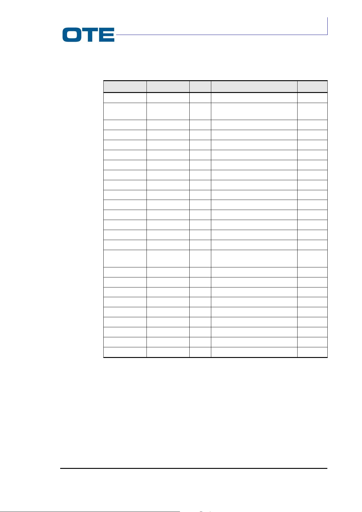
VS 2001
Technical Handbook
Accessories
Tab. 2.5: Pins function of J02 connector
Signal Pin Type Description Level
+8V 1,36 POW stabilised voltage for R/T card 7.2 V
GND
2,3,17,18,20,
31,32,33,34,35
POW ground
Ground
CK2304DA 4 IN serial clock BB. Tx data 0- 3.3 V
LATCH 5 IN timing signal BB Tx data 0 - 3.3 V
ITXD 6 IN serial data component “I” BB Tx 0 - 3.3 V
QTXD 7 IN serial data component “Q” BB Tx 0 - 3.3 V
HIQRXAD 29 OUT serial data i/q BB. Tx 0 – 5 V
HFLGIQ 28 OUT timing serial data BB Tx 0 – 5 V
HCK4608 27 IN master clock for AD7013 0 – 5 V
HCK2304AD 26 OUT control clock data AD7013 0 – 5 V
HDATAAD 25 IN serial control data AD7013 0 – 5 V
HFRAMEAD 24 IN timing control data AD7013 0 – 5 V
SD 8 IN on/off circuits R/T card; 1=off 0 - 3.3 V
TXON 9 IN Tx on/off circuits R/T card Open Coll
RXON
HDATASER 13 IN serial data for EEPROM, synth,
30
IN
Rx on/off circuits R/T card
DAC
Open Coll
0 – 5 V
HCKSER 12 IN serial clock for hdataser 0 – 5 V
HENSINT 16 IN enable for synthesiser 0 – 5 V
HENDAC 14 IN enable for DAC 0 – 5 V
HENEEPROM 15 IN enable for EEPROM 0 – 5 V
SERDATAIN 11 OUT EEPROM data output serial 0 – 5 V
Fref 19 OUT 12.8 MHz reference clock 1 Vpp
BSW 21 IN band switch for VCO WB Open Coll
PAON 10 IN on/off preamp of P.A.; 1=off Open Coll
LD 22 OUT PLL hook up monitor; 0=ok 0 – 5 V
2.3.3 P.A. card
The TETRA vehicular amplifier is housed on the solder side of the R/T card near
the dissipation fins. The P.A. card amplifies the RF input signal coming from the
R/T card in order to supply a power output of 40 dBm in the vehicular radio
operating frequency range (the operating frequency range is different according to
the VS 2001 different versions: see Tab. 1.2). The RF signal amplification is
obtained via a line that consists of a bipolar technology transistor polarised in class
AB, driven by an LDMOS technology power module.
P/N: 779-0373/02
Revision 02
Marconi Proprietary information
Page 41
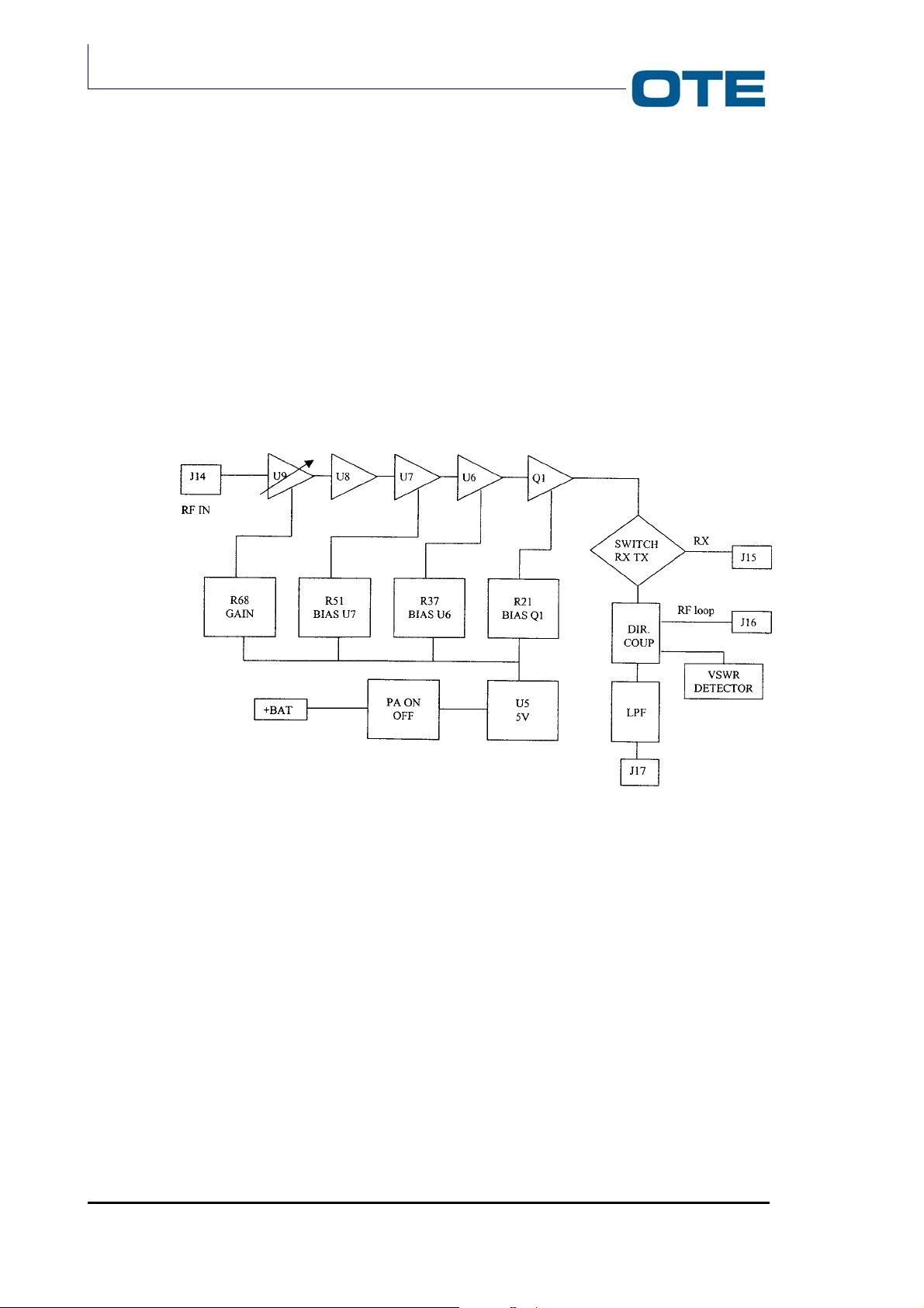
VS 2001
Technical Handbook
Technical Description
The P.A. card interfaces with the Base Band card through the J06 connector. It
also interfaces with the R/T CARD through the MCX type radio-frequency
connectors: J14, J15 and J16. The J14 connector provides the RF signal input
from the VCO. The J15 connector carries the signal from the antenna to the
receiver input. The J16 connector returns the RF signal output to the R/T card and
provides the linearization of the modulation. The amplified radio-frequency signal
exits on the J17 connector and, through proper cable, is connected to the antenna.
2.3.3.1 Functional description
The block diagram of the P.A. card is shown in Fig. 2.13.
Fig. 2.13: Block diagram of the P.A. card
The PA ON OFF is switched on and off by acting directly on the 12 V line where a
P channel MOSFET with low RDS(on) is inserted.
When the signal PAON (see par. 2.3.3.2) is at high logic level: VTX = 12 V and
VRX = 0. When PA ON is at low logic level the values are inverted.
The main task of the PA ON OFF module is to amplify the RF signal generated by
the RT module up to 10 W in the vehicular radio operating frequency range (see
Tab. 1.2).
The RF signal generated by the R/T module, via the J14 connector, is applied to
the first step U9 (variable gain amplifier) used to set PA card gain by means of the
R68 network (see Fig. 2.13).
Then the signal is applied to the second step U8 (monolithic amplifier) where it is
further amplified in order to drive properly the subsequent steps.
Page 42 Marconi Proprietary information
P/N: 779-0373/02
Revision 02
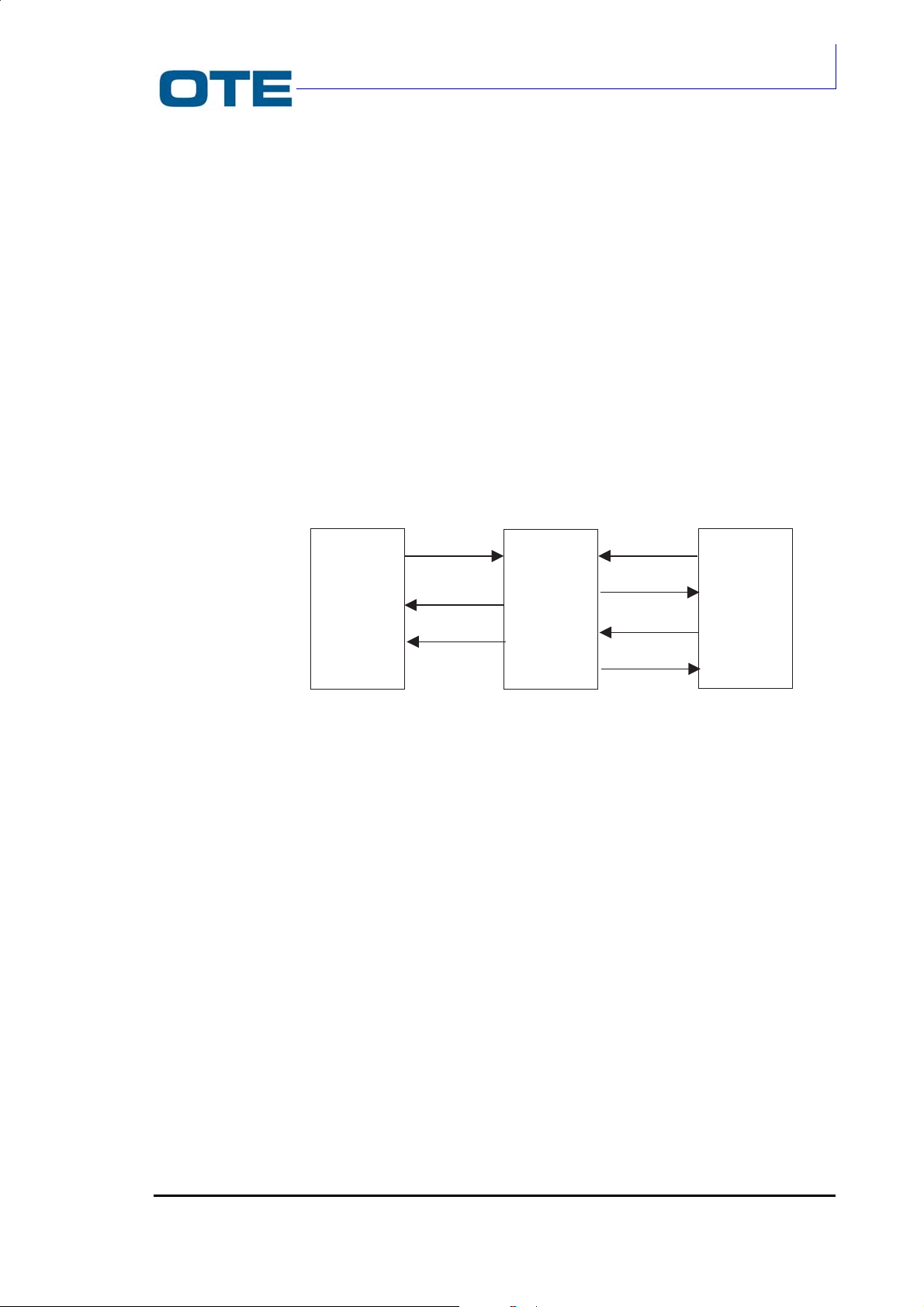
The signal is then adapted and connected to U7 and U6 (transistors LDMOS).
Together with Q1 U7 and U6 are AB class amplifiers whose polarization is fixed by
using the trimmers R51, R37 and R21 respectively.
After the received signal has been properly amplified, it is routed to the RX/TX
switch that is connected, during the receiving phase, to the antenna (J15
connector).
The RF signal is then splitted, by using a directional coupler, into the R/T module
for RF treatment (J16 connector) and to an additional port for ROS monitoring
(VSWR Detector).
Finally, downstream the directional coupler, the signal enters a low-pass filter
(LPF) and then it is connected directly to the antenna (J17 connector).
2.3.3.2 P.A. card Interfacing
The P.A. card interfaces with the R/T card and with the Base Band card as shown
in Fig. 2.14.
VS 2001
Technical Handbook
Accessories
RFIN
R/T P.A. BB
BOARD BOARD BOARD
RFFEEDBACK
RFRECEIVED
PAON
VSWR
12.5V
RFOUT
Fig. 2.14: P.A. card interfacing
The signals exchanged between the P.A. card and the R/T card are:
RF FEEDBACK signal
This signal is picked up directly from the RF signal through the directional coupler
and it is transmitted to the R/T card through the J16 connector. The signal power is
equal to 10dBm.
RFIN signal
This signal is the input (through the J14 connector) of the P.A. line up loop. The
signal power is less than +10dBm.
P/N: 779-0373/02
Revision 02
RF RECEIVED signal
This signal is the RF signal received at the antenna and sent to the receiver
through the J15 connector.
The signals exchanged between P.A. card and Base Band card are:
Marconi Proprietary information
Page 43

VS 2001
Technical Handbook
Technical Description
12.5 Volt signal
This signal is the voltage supplied by the vehicular battery (12 Volt) through the
J06 connector (pin 5, 6).
PAON signal
This signal is the switching on/off command for the PA ON OFF amplifier. It is
transmitted through the pin 1 of the J06 connector.
• PAON = High: low output impedance (ground);
• PAON = Low: high output impedance.
VSWR signal
This analogue signal (pin 2 of J06 connector) is correlated to the ROS measured at
the P.A. output connector.
RFOUT signal
This is the output signal of the P.A. line up loop (connector J17). The signal power
is less than or equal to +40 dBm in the vehicular radio operating frequency range
(see Tab. 1.2).
Page 44 Marconi Proprietary information
P/N: 779-0373/02
Revision 02
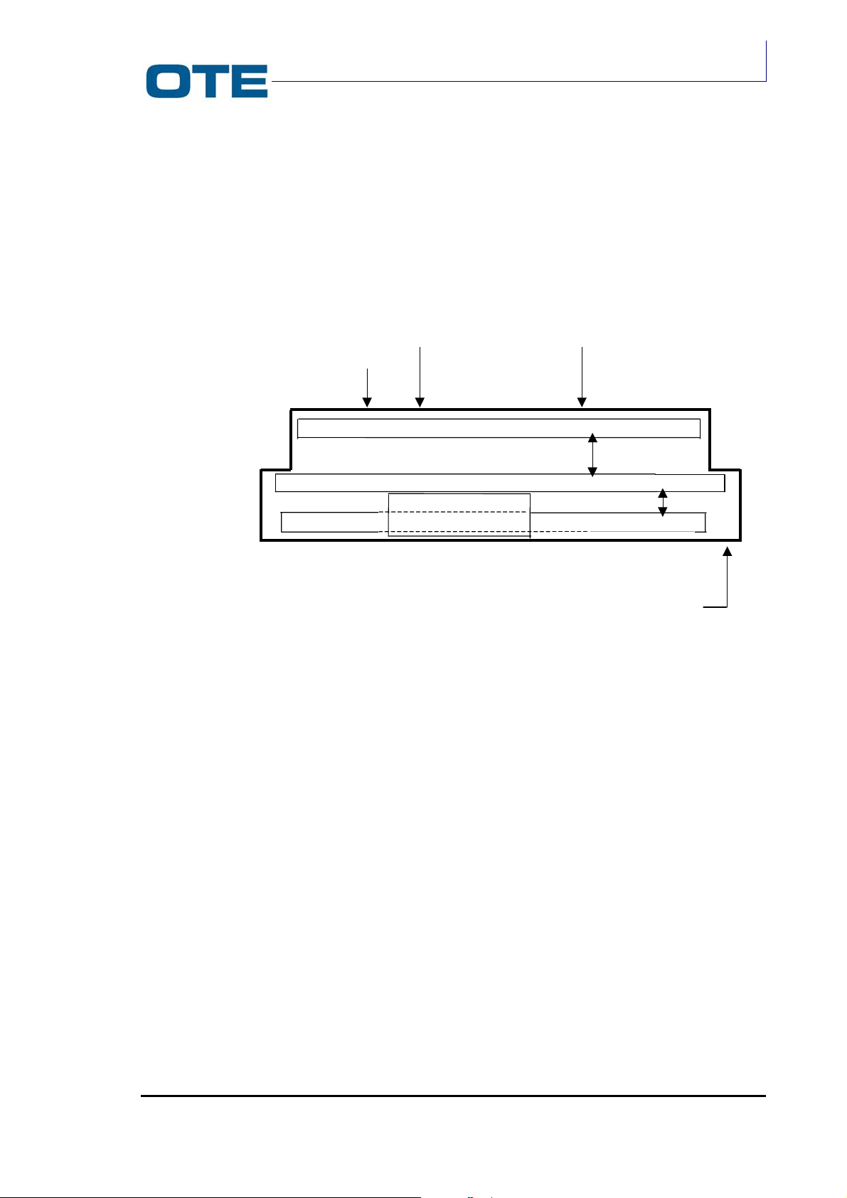
2.4 FPG1/A FRONT PANEL
The FPG1/A Front Panel is the radio remote control that integrates all of the user
interface and accessories interface functions. The structure of the Front Panel is
shown in Fig. 2.15.
VS 2001
Technical Handbook
Accessories
Connectors to:
INTERFACE BOARD
LOGIC + DISPLAY BOARD
DB 15
Connector
rigid coupling conn.
flex conn.
KEYBOARD BOARD
J1, J2 connectors
DB 37
Connector
PEI
Connector
DISPLAY BOARD
Fig. 2.15: Mechanical structure of the Front Panel
The Front Panel contains three boards (logic + display board, keyboard board and
interface board). On the rear panel it supports three type D connectors to the radio
unit module, loudspeaker, microphone and peripheral equipment. On the front
panel there are two rotary knobs (for volume and group selection) and two LEDs
(indicating transmission and reception status).
2.4.1.1 Control panel architecture
The following boards are contained in the control panel:
• The keyboard, located under the display, provides connection for the 25 keys
of the front side of the front panel, and supports the hands-free microphone
(which is located on the board itself); a flex connector collects the signals
coming from the switches (volume and group selectors) and the connectors
for audio accessories and PEI (located on the front panel) towards the Logic +
display board;
P/N: 779-0373/02
Revision 02
Marconi Proprietary information
Page 45

VS 2001
Technical Handbook
Technical Description
• The logic + display board, located on the internal side of the rear cover,
contains the circuitry for display control and interfacing;
• The interface board, located on the rear side of the Front Panel behind the
“Logic+display” board, hosts the connectors, which are available on the
control, panel rear cover.
The architecture of the Front Panel logic board is shown in Fig. 2.16.
Ram Flash
Display
Module
Groups
Volume
Red + green leds
µP
Keyboard
Fig. 2.16: Block diagram of the Front Panel
Radio Unit
interface
Microphone /
Handset
interface
RS232
Page 46 Marconi Proprietary information
P/N: 779-0373/02
Revision 02

VS 2001
Technical Handbook
Accessories
The microprocessor provides the following software functions:
• management of “Groups” and “Volume” potentiometers (via digital I/O), 25 key
keyboard, display and leds (green and red);
• management of operating program and set-up data download;
• management of all signals to/from Radio Unit.
The controller interface, via two RS232 asynchronous serial lines via a suitable
interface module between the control panel and the radio unit.
The keyboard has the following characteristics: 25 keys matrix arranged and
backlit under microprocessor control. The keyboard condition is controlled via
microprocessor via I/O ports.
The display has the following characteristics: 160x80 pixels LCD full graphic
display; the led backlighting is activated under microprocessor control. The display
status is controlled by a microprocessor via an 8 bit bus.
The display module hosts the controller, which manages the LCD device.
The contrast regulation of the LCD is realized by varying the biasing of the glass.
The function is controlled by microprocessor.
The display allows visualizing the information with different character dimensions.
This function allows visualizing the text area in three rows of ten characters each
and characters with doubled height.
Apart from the alphanumeric information, the display allows visualizing a series of
symbols that allow the user to immediately see the operating status of the system.
2.4.1.2 External interfacing
Two connectors are available on the front side of the control panel. They carry out
the following functions (see section 3 for detailes):
• 7 pin connectors for microphone /headset (J1)
• 7 pin connectors for RS232 interface (four lines) (J2)
The following connectors for multipurpose functions:
• 15 pin connector to radio unit (P4)
• 9 pin connector (PEI) (P3)
• 37 pin connector to radio unit.
See section 3 for details on cabling and connections.
P/N: 779-0373/02
Revision 02
Marconi Proprietary information
Page 47

VS 2001
Technical Handbook
Technical Description
2.5 E-WHERE/FPG1A MODULE
The E-WHERE module is used in the vehicle configuration equipped with a GPS
E-WHERE module.
The equipment by means of the interfacing with FPG1/A, allows the use of
equipment like VT and VS (vehicle radio).
E-WHERE module make available the PEI serial line for a connection for PC on
FPG1/A; it avoid possible conflict with the GPS equipment that also used, of
default, the PEI serial line.
In the Fig. 2.17 the configuration is shown:
Fig. 2.17: Vehicular Setting-up with E-WHERE/FPG1 Module
For mains supply and for connection with other equipments, the E-WHERE module
used the following cables (shown in Fig. 2.17):
• EXCHANGE DATA CABLE BETWEEN FPG1/A and E-WHERE interface
module (this cable has a D9 female connector (FEI-FPG1/A rear side) and a
RJ9 (4 position) connector (E-WHERE interface module side) (the cable is 6
m long).
• MAINS SUPPLY CABLE BETWEEN E-WHERE interface module and GPS-
E-WHERE module: this cable connects with a RJ45/RJ45 (8 position)
male/male connector, the E-WHERE interface module with the GPS- EWHERE module.
• EXCHANGE DATA CABLE BETWEEN E-WHERE INTERFACE MODULE
and GPS E-WHERE MODULE: this cable connects with a RJ12/RJ12 (6
position) male/male connector, the E-WHERE interface module with the GPS
E-WHERE module (the cable is 0,5 m long).
The kit of this three cables is the E-WHERE/FPG1 module (P/N 771-0955/01.01).
Page 48 Marconi Proprietary information
P/N: 779-0373/02
Revision 02

Technical Handbook
2.5.1 System Architecture with E-WHERE/FPG1/A Interface
The block diagram of the configuration in the following figure is represented:
Antenna
AN
DB25
DB37
VS 2001
VS 2001
Accessories
FPG1/A
Hands free kit
Loudspeaker
DB9
DB15
Battery
E-WHERE/FPG1
RJ9
RJ12
interface
RJ45
Odometer
RJ45
GPS
E-WHERE
RJ12
J1
ANT GPS
GPS
Antenna
Fig. 2.18: Vehicle configuration with E-WHERE/FPG1/A Module
2.5.2 Mechanical description of E-WHERE/FPG1/A Module
12 Vdc
GPS
P/N: 779-0373/02
Revision 02
Fig. 2.19: E-WHERE/FPG1/A Module
Marconi Proprietary information
Page 49

VS 2001
Technical Handbook
Technical Description
The kit (P/N 771-0955/01.01) contains 4 screws 3,5x25 (P/N 61510-56/001) for the
installation. The module is composed by a switch driven by RTS signal of PEI (pin
7 of FPG1/A serial line).
According to RTS signal logic levels, the switch is opened or closed for TX and RX
signals of RS232 towards E-WHERE module.
In details:
Logic Level RTS Electric Panel RTS Relé State
0 12 V Relé open
1 (default) -12 V Relé close
Note
The D9 serial connector (rear sides of remote control) is fisically in parallel with the data connector (front
side of remote control). When the kit is installed, by means management of the RTS signal it’s possible
to drive the switch. This connector is used for download the software towards the radio unit and the
remote control.
In Fig. 2.20 the equipment description is shown:
Fig. 2.20: Scheme of E-WHERE Module
Page 50 Marconi Proprietary information
P/N: 779-0373/02
Revision 02

2.5.3 Pin out connector
The E-WHERE/FPG1/A module has three female connectors:
• RJ45 (8 pin);
• RJ12 (6 pin);
• RJ9 (4 pin, on the apposite side).
In Tab. 2.6, Tab. 2.7, Tab. 2.8 are shown the pin out:
Tab. 2.6: Pin out connector J1
Pin Signal
1 +5 VDC
3
Tab. 2.7: Pin out connector J2
GND
VS 2001
Technical Handbook
Accessories
Pin Signal
2 GPS Data from
3 GPS Data to
5 GND
Tab. 2.8: Pin out connector J3
Pin Signal
1 RTS
2 Data to FPG1
3 Data from FPG1
4 GND
P/N: 779-0373/02
Revision 02
Marconi Proprietary information
Page 51

VS 2001
Technical Handbook
Technical Description
PAGE INTENTIONALLY LEFT BLANK
Page 52 Marconi Proprietary information
P/N: 779-0373/02
Revision 02

Technical Handbook
3. INSTALLATION
3.1 INTRODUCTION
This section is addressed to personnel with experience in the installation of this
equipment type. It also contains the unpacking instructions, the storage and
transport requirements.
3.2 UNPACKING INSTRUCTIONS AND STORAGE, TRANSPORT
REQUIREMENTS
VS 2001
Accessories
3.2.1 Unpacking
No particular operations are required for the unpacking. However, it is advisable to
leave the material in its original packing until it is to be installed. Once the packing
is opened, make sure that all the items listed in the forwarding document are
present. Moreover, check the condition of the contents to ensure that no damage
was sustained during transport and storage phases. Save the original packing for
possible future use.
3.2.2 Storage
This paragraph is addressed to the personnel responsible for receiving and storing
equipment that are not to be installed immediately.
Avoid impact or excessive pressure on the packing in order to prevent damages to
the contents.
The unopened packing should be stored in an environment with temperature
between –40°C and +70°C and relative humidity not exceeded the value of 90%.
3.2.3 Repackaging and transport
The repackaging criteria may differ according to the means of transport, the
environmental conditions, the period of no-use, the storage time and conditions.
The original container, if well preserved, guarantees any further transport and/or
storage within the limits specified in the previous paragraph. For greater protection
during transport and/or storage, it is always advisable to repack the equipment as it
was originally packed.
P/N: 779-0373/02
Revision 02
Marconi Proprietary information
Page 53
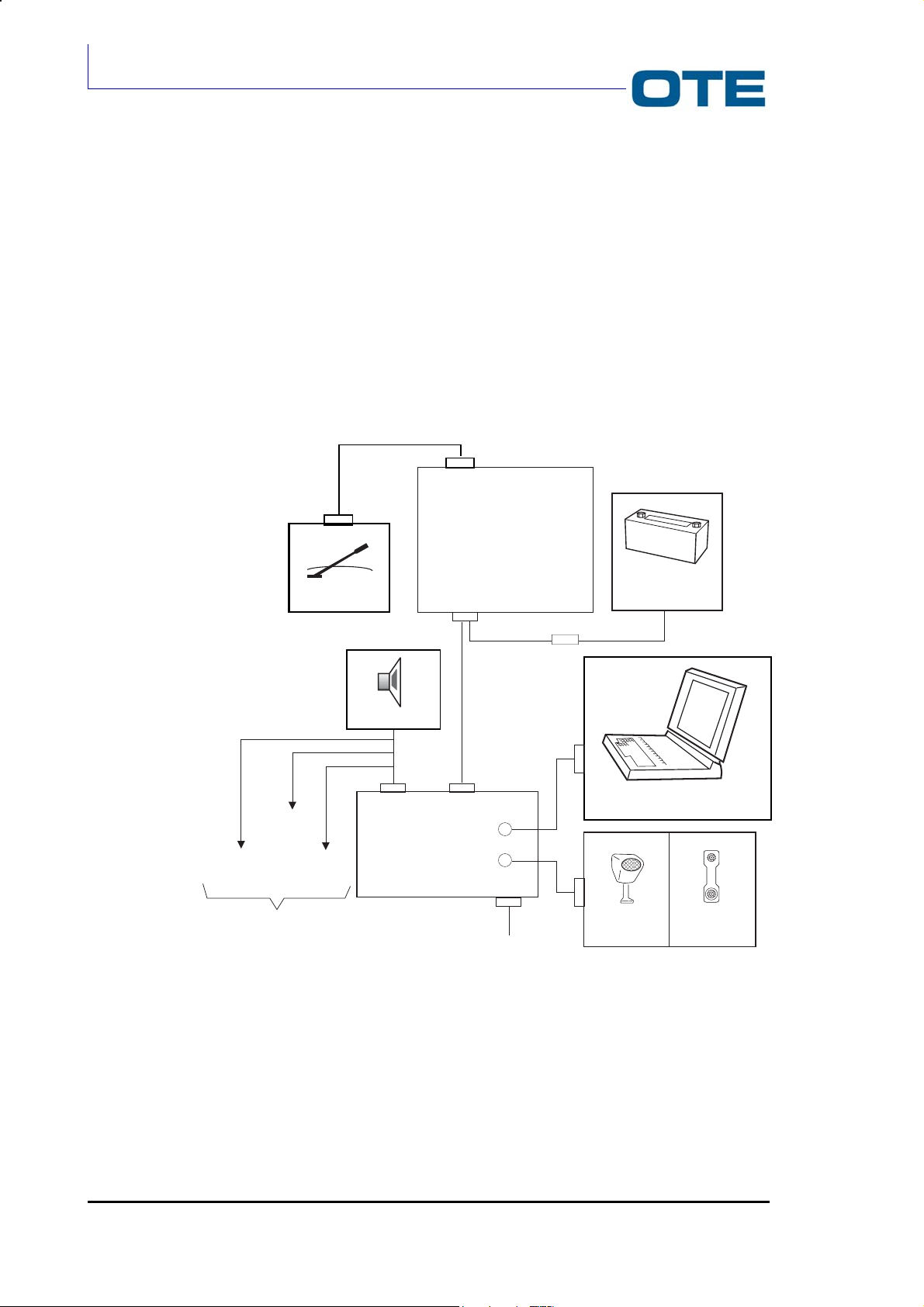
VS 2001
Technical Handbook
Installation
3.3 INSTALLATION CONFIGURATION
The complete list of available items is given in Tab. 1.3.
3.3.1 Vehicle configuration without E-WHERE / FPG1/A Module
The configuration of the VS 2001 radio equipment depends on the vehicle where it
is to be installed on. In Fig. 3.1 and a typical car and motorcycle configuration is
respectively shown.
VS 2001
MICROPHONE
Only for hands free kit
EXT.
PTT
Antenna
ALARM
EXT.
Loudspeaker
DB15
FPG1/A
RADIO UNIT
DB25
DB37
J2 (PEI)
J1
DB9 (PEI)
FUSE 16A (6-25 mm)
JB
Microphone
Car Battery
PC
Handset
Fig. 3.1: VS 2001 configuration (installed on a car) without E-WHERE / FPG1/A
Page 54 Marconi Proprietary information
P/N: 779-0373/02
Revision 02
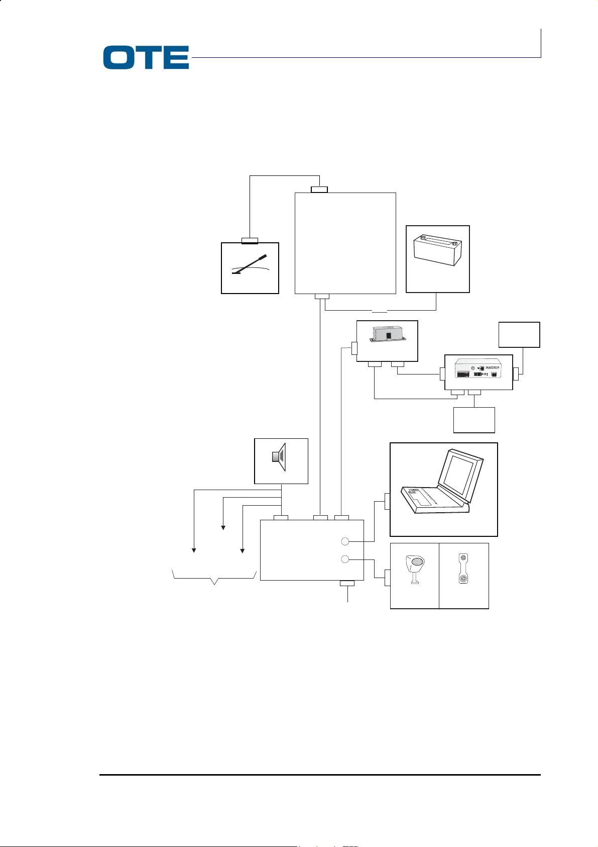
Technical Handbook
3.3.2 Vehicle configuration with E-WHERE / FPG1/A Module
VS 2001
RADIO UNIT
VS 2001
Accessories
EXT.
PTT
MICROPHONE
Only for hands free kit
Antenna
ALARM
EXT.
Loudspeaker
DB15
FPG1/A
DB25
DB37
J2 (PEI)
FUSE 16A (6-25 mm)
RJ9
E-WHERE/FPG1
Interface
RJ12
DB9
J1
DB9 (PEI)
JB
Microphone
Car Battery
RJ45
RJ45
GPS E-WHERE
RJ12
PC
Handset
GSM
I/O
CAN HOST
12 Vdc
GPS
GPS
SPK MIC
POWER
L1
L2
ANTENNA
GPS
P/N: 779-0373/02
Revision 02
Fig. 3.2: VS 2001 configuration (installed on a car) with E-WHERE / FPG1/A Module
Marconi Proprietary information
Page 55
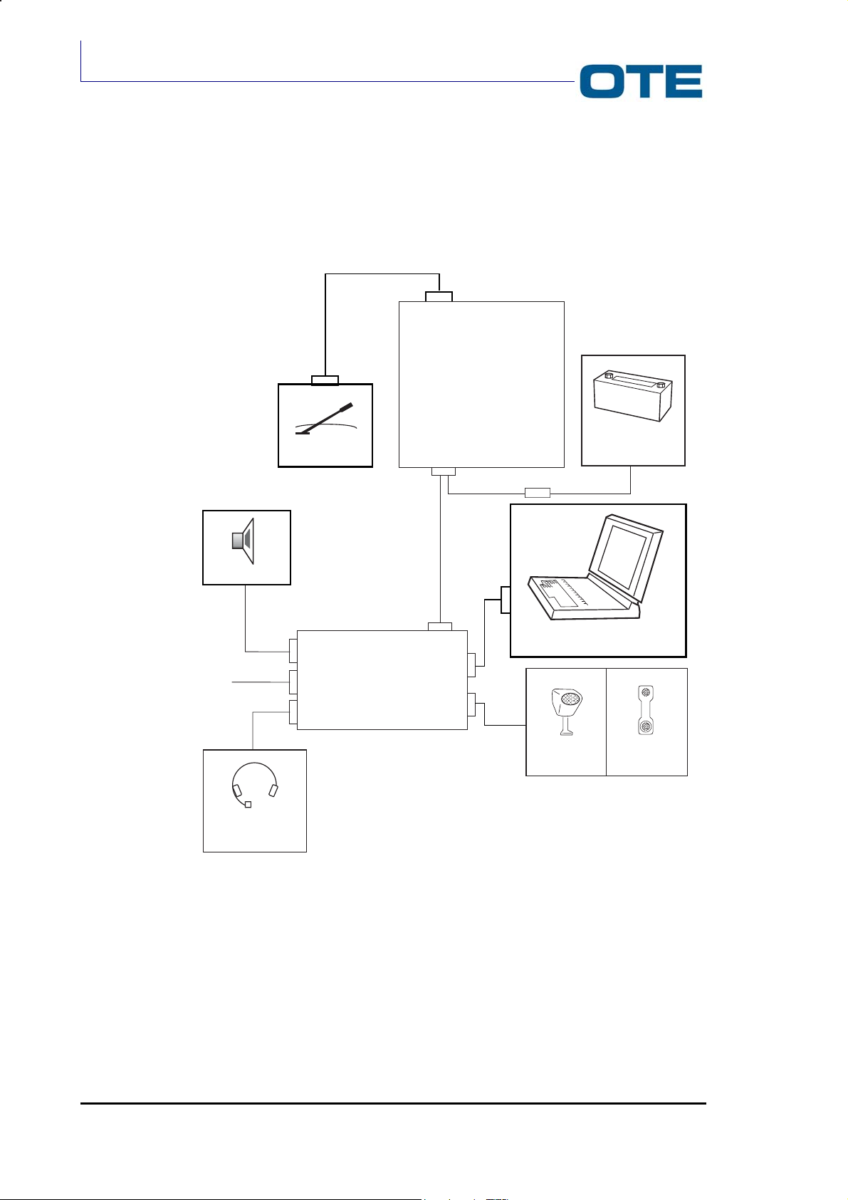
VS 2001
Technical Handbook
Installation
3.3.3 Motorcycle configuration
VS 2001
RADIO UNIT
Loudspeaker
EXT.PTT
HELMET
MICROPHONE
Antenna
FPG1/A Support
DB25
DB37
J2 (PEI)
J1
FUSE 16A (6-25 mm)
JB
Microphone
Car Battery
PC
Handset
Fig. 3.3: VS 2001 configuration (installed on a motorcycle)
Page 56 Marconi Proprietary information
P/N: 779-0373/02
Revision 02
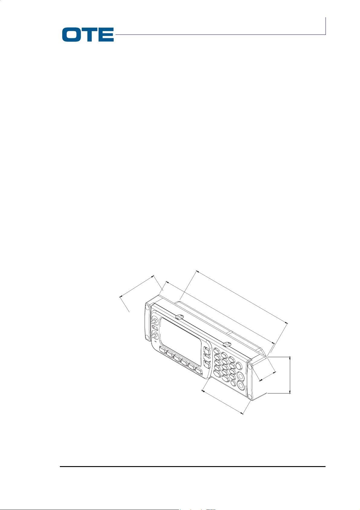
3.4 INSTALLATION OF THE CONTROL PANEL
The control panel dimensions are shown in Fig. 3.4 and Fig. 3.5.
3.4.1 3.6.1 Installation of the control panel in a car
In the vehicle configuration the control panel can be:
• Mounted into the Car Radio cavity
• Mounted in adjustable bracket:
- On the dashboard
- Under the dashboard
- Suspended from the roof of the car
• Mounted in lite braket
VS 2001
Technical Handbook
Accessories
The first type of mounting is realized by using the car radio cavity. The second type
of mounting is realized by means of a turntable support consisting of two
independent brackets connected by means of a pin. The turntable support allows
horizontal (± 45°) and vertical rotation.
The third type has a support that not allows the horizontal rotation.
49.5
210
180
29.5
62.6
P/N: 779-0373/02
Revision 02
83.1
Fig. 3.4: Control panel
Marconi Proprietary information
Page 57
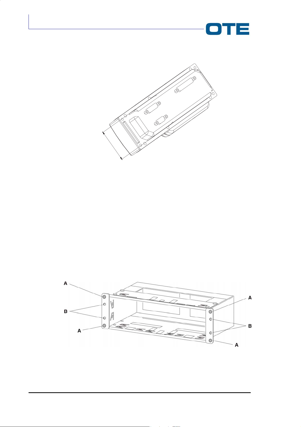
VS 2001
Technical Handbook
Installation
52
Fig. 3.5: Control panel (rear side)
3.4.1.1 Installation in the car radio cavity
Follow the instructions given below.
1. Drill four holes in the dashboard corresponding to “A”. The holes should have
a diameter of 9 mm.
2. Insert the bracket into the car cavity.
3. Bend the tabs to suit.
4. (Optional according to the type of vehicle). Insert the appropriate screws in
holes “B” (Ø = 3.5mm). Screws are supplied with a kit that contains 5 screws
of 25mm in length and 5 screws of 50 mm in length).
5. Insert the Control Panel into the bracket and fix the captive screws.
Fig. 3.6: Bracket for control panel (installation in the car radio cavity)
Page 58 Marconi Proprietary information
P/N: 779-0373/02
Revision 02
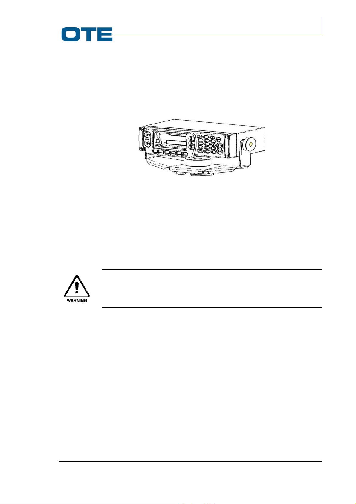
3.4.1.2 Installation with adjustable bracket
After disassembling the assembly shown in Fig. 3.7, follow the instructions of the
next list referring to Fig. 3.8.
VS 2001
Technical Handbook
Accessories
Fig. 3.7: Adjustable bracket
1. Take out the sticker form washer (2) and stick the washer on the base of the
bracket (7).
2. Mount the bracket (7) to the surface where the control panel is required
ensuring that the mounting arrows (11) point across the width of the car.
By means of holes (10) fix the bracket (1) with a fastening system that
fits with the mechanical characteristics of the support base.
3. Put bracket (1) on the pin (12).
4. Put washer (8) in pin (12).
5. Mount knob (4).
6. Stick the washers (3) on the box (6), fitting in pins (13).
7. Mount box (6) on bracket (1), using the relevant holes (14).
8. Mount on pins (13) washers (9).
9. Mount knobs (5).
10. Connect cables to the rear connectors of the control panel.
11. Mount the control panel by fixing the captive screws.
P/N: 779-0373/02
Revision 02
Marconi Proprietary information
Page 59
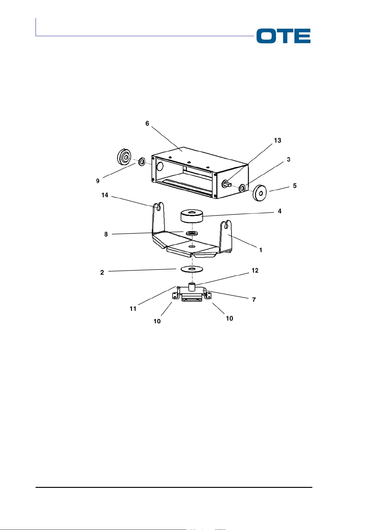
VS 2001
Technical Handbook
Installation
Fig. 3.8: Installation of the control panel in the adjustable bracket
Page 60 Marconi Proprietary information
P/N: 779-0373/02
Revision 02

3.4.1.3 Installation with lite bracket
Follow the instructions of the next list referring to Fig. 3.9.
VS 2001
Technical Handbook
Accessories
Fig. 3.9: Installation of the Control Panel in the lite bracket
1. Mount the bracket (1) to the surface where the control panel is required.
By means of holes fix the bracket (1) with a fastening system that fits
with the mechanical characteristics of the support base.
2. Stick the washers (2) on the box (3), fitting in pins (4).
3. Mount box (3) on bracket (1), using the relevant holes (5).
4. Mount on pins (4) washers (6).
5. Mount knobs (7).
6. Connect cables to the rear connectors of the control panel.
7. Mount the control panel by fixing the captive screws.
P/N: 779-0373/02
Revision 02
Marconi Proprietary information
Page 61

VS 2001
Technical Handbook
Installation
3.4.2 Installation of the control panel in a motorcycle
In the motorcycle configuration the control panel is mounted in a support that has
the dimensions shown in the Fig. 3.10.
For the fixening of the remote control assembly on the motorcycle in the control
panel support there are four threaded holes. The installation requirers an
opportune bracket.
±0,10
200
100
= =
±0,10
Pressacavo PG13,5
==
==
11
34
± 0,10
prof.utile 9mm
N° 4 fori M4
2,4
Ø 24
Fig. 3.10: Remote control assembly
The control panel support presents the cables for the connection with the other
blocks of the system. These connection are displayed in the Fig. 3.11.
Page 62 Marconi Proprietary information
P/N: 779-0373/02
Revision 02

VS 2001
Technical Handbook
Accessories
To J2 connector of
VT radio mobile or
GPS device
To loudspeaker
To helmet
PTT handle
command
Fig. 3.11: Connection of remote control assembly
P/N: 779-0373/02
Revision 02
Marconi Proprietary information
Page 63

VS 2001
Technical Handbook
Installation
3.5 RADIO UNIT INSTALLATION
The Radio Unit module is fixed with nuts in the car/motorcycle boot by means of
the proper bracket shown in Fig. 3.12.
FLO5N2G
NUT
Fig. 3.12: Bracket for the Radio Unit module installation
The Front Panel and the Radio Unit module are connected together trough a cable
that is 6 meters long.
Page 64 Marconi Proprietary information
P/N: 779-0373/02
Revision 02

3.6 ANTENNA INSTALLATION
The best position for the antenna installation is the centre of the vehicle roof (if
permitted). If the vehicle is not equipped with the hole for the antenna fastening,
make a 19mm diameter hole (remove all residuals of paint near the fastening
hole).
Proceed as follows to correctly install the antenna:
• Disassemble the antenna.
• Insert the coaxial cable in the installation hole from the outside of the vehicle
without assembling the coaxial connector.
• Slide the cable in until the antenna assembly support is connected to the
vehicle.
• Screw in the stop nut.
• Insert the gasket with the grooved side up.
• Carefully insert the sealing block on the gasket and screw it in.
• Connect the antenna to the block using the wing nut.
• Assemble the coaxial connector.
VS 2001
Technical Handbook
Accessories
P/N: 779-0373/02
Revision 02
Marconi Proprietary information
Page 65

VS 2001
Technical Handbook
Installation
3.7 EXTERNAL CONNECTORS
In this chapter all external connectors are described in detail and Pin function are
also explained. The Radio Unit module (see Fig. 3.13) hosts:
• Antenna connector (J18)
• Rear connector (P01)
On the FPG1/A Frontal Panel the following connectors are located:
• DB 37 (P02) connector;
• DB 15 (P04) connector;
• DB 9 (PEI) connector.
On the FPG1/A front side J1 and J2 connector are placed.
3.7.1 Antenna connector J18
It is a TNC female type connector located on the rear side (heat sink side) of the
Radio Unit module.
3.7.2 Main rear connector (P01)
The 25-pin male D-type connector located on the rear side of the Radio Unit
module is described in Tab. 3.1.
Antenna
connector
Fig. 3.13: Rear view
Page 66 Marconi Proprietary information
Rear connector (P01)
P/N: 779-0373/02
Revision 02

Technical Handbook
Tab. 3.1: P01 Rear connector pin functions
Signal Pin Function Level
ACC-SP
ALARM
1
TURN ON/TURN OFF COMMAND
0=TURN ON IF TRANSCEIVER OFF;
TURN OFF IF TRANSCEIVER ON
14 INPUT FROM ALARM PUSH-BUTTON
0 to+BATT
0 to +5 V
0=ALARM
PTT-MAN
2 PTT INPUT FROM OUTSIDE
0 to +5 V
0 = EQUIPMENT IN TX
ALT-A
HOOK
ALT-B
VBATT-INT
MUTE
15 LF OUTPUT LOUDSPEAKER (FIRST
TERMINATION)
3 HANDSET ON/OFF HOOK
0=HANDSET OFF HOOK
16 LF OUTPUT LOUDSPEAKER (SECOND
TERMINATION)
2.8 Vrms max (7.8
W on 4Ω)
0 to +5 V
2.8 Vrms max (7.8
W on 4Ω)
4 BATTERY VOLTAGE IF EQUIPMENT ON Battery Voltage -
Voltage Drop
17 LOUDSPEAKER ENABLING
0 to +BATT
0 = LF ENABLED
MIC-R
232 FROM FG
RIT-MIC
EXT TO 232 FG
HEADSET
GND
RXD-ACCESS.
TXD-ACCESS.
GND
RXD-PEI
TXD-PEI
RTS-PEI
CTS-PEI
VBATT+
VBATT-
5 MICROPHONE SIGNAL INPUT (rear
side)
200 mVrms.
18 SERIAL LINE (TOWARDS EQ) STANDARD 232
6 MICROPHONE SIGNAL GROUND 0 V
19 SERIAL LINE (FROM EQUIPMENT) STANDARD 232
7
LF OUTPUT TOWARDS HEADSET
1.75 Vrms. / 300Ω
20 GROUND 0 V
8 GPS SERIAL LINE (TOWARDS
EQUIPMENT)
STANDARD 232
21 GPS SERIAL LINE (FROM EQUIPMENT STANDARD 232
9 GROUND 0 V
22 PEI SERIAL LINE (TOWARDS
EQUIPMENT)
STANDARD 232
10 PEI SERIAL LINE (FROM EQUIPMENT) STANDARD 232
23 PEI SERIAL CONTROL (FROM
EQUIPMENT)
11 PEI SERIAL CONTROL (TOWARDS
EQUIPMENT)
STANDARD 232
STANDARD 232
12/24 POSITIVE POLE POWER SUPPLY +10.8, +15.6 V
13/25 NEGATIVE POLE POWER SUPPLY 0V
VS 2001
Accessories
3.7.3 Front panel connectors
3.7.3.1 Front connectors
The J1 and J2 front external connectors of the FPG1/A are shown in Fig. 3.14.
P/N: 779-0373/02
Revision 02
Marconi Proprietary information
Page 67

VS 2001
Technical Handbook
Installation
2
3
4
2
3
4
7
1
6
5
J1
7
1
6
5
J2
Fig. 3.14: FPG1/A front connectors
The J1 7-pin connector (see Fig. 3.14) provides the connection of a microphone or
an handset.
The J2 7-pin PEI connector (see Fig. 3.14) provides the connection of an external
PC.
The pin functions of J1 connector and of J2 connector are listed in Tab. 3.2 and
Tab. 3.3.
Tab. 3.2: Pin functions of J1
Signal Pin Function Level
MICRO
3 MICROPHONE INPUT 3.2 mV / Dynamic
microphone
HEADSET
CUFFIA
PTT.MAN
5 LF OUTPUT LOUDSPEAKER (FIRST
TERMINATION)
4 PTT INPUT FROM OUTSIDE
1.75 Vrms. / 300 Ω
0 to +BATT
0 = EQUIPMENT IN TX
RIT MICRO
+12
2 MICROPHONE GROUND 0 V
7 RELAY 12 (ACTIVATED BY HOOK) BATTERY VOLTAGE -
VOLTAGE DROPS
GND
HOOK
1 GROUND 0V
6 GENERAL PURPOSE INPUT 0 to +5 V
Page 68 Marconi Proprietary information
P/N: 779-0373/02
Revision 02
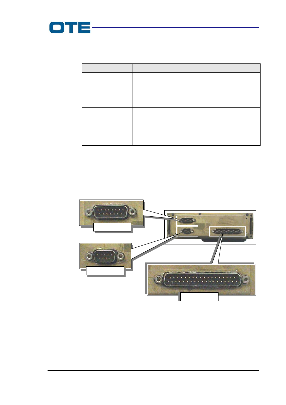
VS 2001
)
Technical Handbook
Accessories
Tab. 3.3: Pin functions of J2
Signal Pin Function Level
ALARM 4 INPUT FROM ALARM PUSH-BUTTON
0=ALARM
0 to +5 V
GND 5 GROUND 0 V
DATA FROM PC 3 FRONT PANEL SERIAL LINE (FROM
EQUIPMENT)
DATA TO PC 2 FRONT PANEL SERIAL LINE
(TOWARDS EQUIPMENT)
Standard RS232
Standard RS232
RTS FROM PC 7 FRONT PANEL SERIAL CONTROL Standard RS232
CTS TO PC 6 FRONT PANEL SERIAL CONTROL Standard RS232
PTT 1 PUSH TO TALK 0 to +5 V
3.7.3.2 Rear side connectors
The FPG1/A rear connectors are shown in Fig. 3.15.
DB 15
DB 9 (PEI
DB 37
Fig. 3.15: FPG1/A rear side connector
The DB37 connector provides the interfacing of the FPG1/A to the Radio Unit
module.
The pin functions of the DB37 connector are listed in Tab. 3.4.
P/N: 779-0373/02
Revision 02
Marconi Proprietary information
Page 69

VS 2001
Technical Handbook
Installation
Tab. 3.4: DB37 connector pin out
Pin Function
1 GND – POWER
2
3 NOT USED
4 LOUD SPEAKER LOOP-BACK
5 NOT USED
6 ALT – A
7 NOT USED
8 NOT USED
9 VBATT_INT
10 NOT USED
11 NOT USED
12 NOT USED
13 ACC – SP
14 RXD PEI 232
15
16 TXD PEI 232
17
18 NOT USED
19 NOT USED
20 NOT USED
21 NOT USED
22 NOT USED
23 NOT USED
24 ALT – B
25 MIC – R
26 ALARM
27 MIC LOOP – BACK
28 VBATT – INT
29 NOT USED
30 NOT USED
31 232 DATA FROM FPG1/A
32 GND OPTO
33 PTT – MANUAL
34 232 DATA TO FPG1/A
35 HEAD PHONE
36 NOT USED
37 GND POWER
The 9-pin PEI connector, as well as the J1 front connector, provides the
connection of an external PC.
NOT USED
NOT USED
NOT USED
Page 70 Marconi Proprietary information
P/N: 779-0373/02
Revision 02
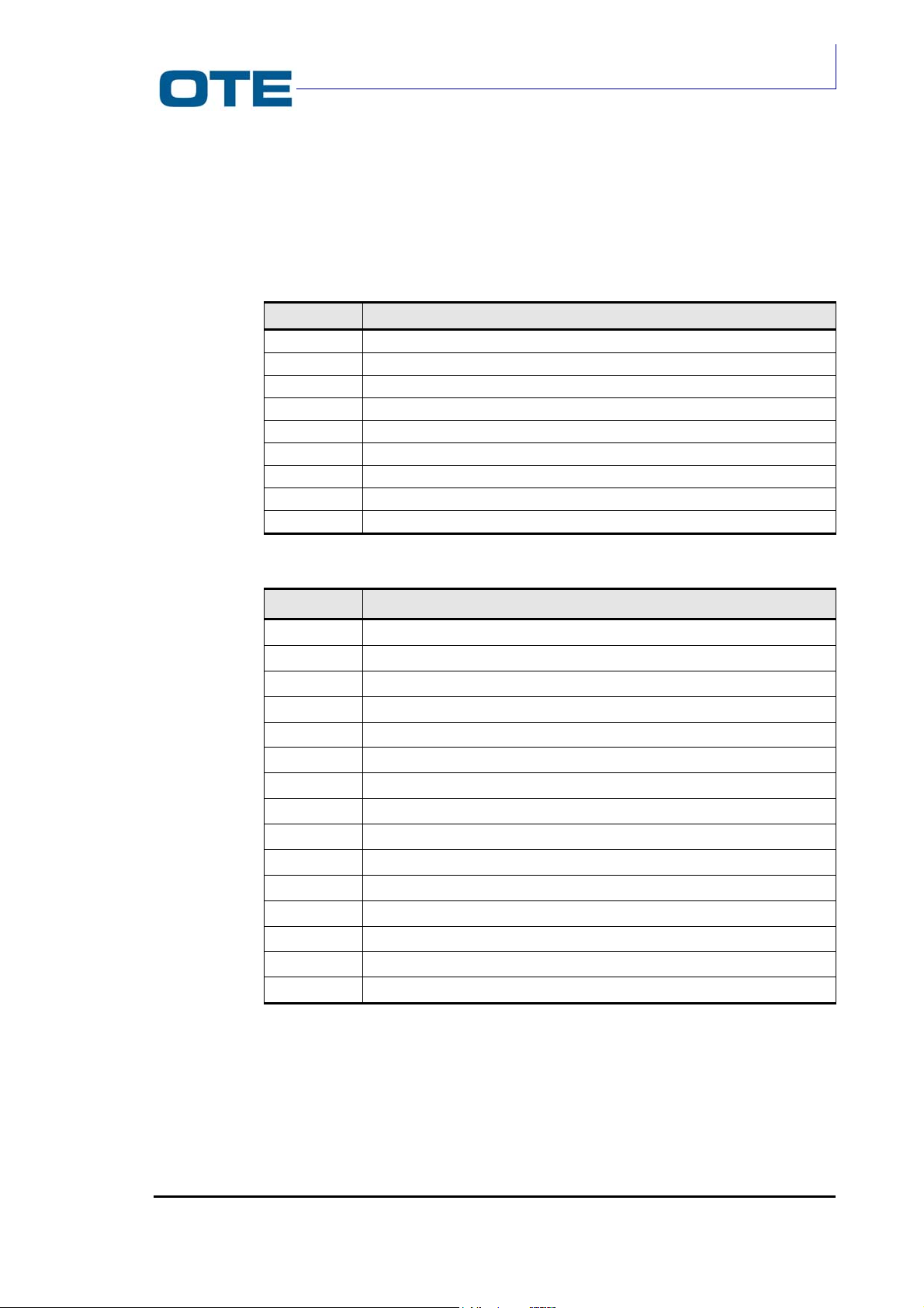
VS 2001
Technical Handbook
Accessories
The PEI connector pin functions are listed in Tab. 3.5.
The DB15 connector (P04) allows to connect the external loudspeaker, the
external alarm control, the external Push To Talk (PTT) button and the external
microphone. The pin functions of the P04 connector are listed in Tab. 3.6.
Tab. 3.5: PEI connector pin functions
Pin Function
1 Alarm In
2
Data to PC (PEI)
3 Data from PC (PEI)
4 PTT In ext. (for Boot)
5
GND
6 Data for control panel
7 RTS for PC (PEI)
8
CTS for PC (PEI)
9 Data from Control Panel
Tab. 3.6: P04 connector pin functions
Pin Function
1
Microphone IN
2 PTT IN ext
3 Low frequency (a) for loudspeaker
4 Low frequency (b) for loudspeaker
5 Configurable serial line
6 GND
7 Hook input
8 Audio frequency amplifier ON/OFF
9 External alarm input
10 Unbalance headset output
11 Aux1
12 Microphone return
13 Not used
14 Not used
15 Not used
Relatively to the FPG1/A front side the J1 connector pin out is reported in Tab. 3.3
and the J2 connector pin out is reported in Tab. 3.2.
P/N: 779-0373/02
Revision 02
Marconi Proprietary information
Page 71

VS 2001
Technical Handbook
Installation
3.8 ELECTRICAL CONNECTIONS
In this chapter the cables for the VS 2001 equipment electrical connections are
described.
In Fig. 3.16 the multifunctional cable, to be connected to the Front Panel through
the DB15 connector (P04), is shown.
To FPG1/A
LOUDSPEAKER
MICROPHONE
ALARM EXT
PTT EXT
Fig. 3.16: Cabling between FPG1/A and accessories
POWER
To FPG1/A
Fig. 3.17: Cabling between FPG1/A and Radio Unit module
Page 72 Marconi Proprietary information
AUX.
DEVICE
TO VS 2001
RADIO UNIT
P/N: 779-0373/02
Revision 02
 Loading...