


 Loading...
Part No. OS3-322
R
MX-50II
PROFESSIONAL TAPE RECORDER
OPERATION AND MAINTENANCE MANUAL
FIFTH EDITION
Printed: June 1996
Ed 5 (GK)
Copyright © 1991, 1992, 1993, 1994, 1996 by Otari, Inc.
Printed in Japan
This manual may not be reproduced by any means without written permission.

WARNING
This equipment generates, uses and can radiate radio frequency energy and if not installed and used in accordance with the instructions manual, may cause interference to radio communications.
It has been tested and found to comply with the limits for a Class A computing device pursuant to Subpart J of Part 15 of FCC Rules, which are designed to provide reasonable protection against such interference when operated in a commercial environment. Operation of this equipment in a residential area is likely to cause interference in which case the user at this own expense will be required to take whatever measures may be required to correct the interference.

CAUTION
To prevent fire or shock hazard:
Do not expose this unit to rain or moisture.
Do not remove panels (unless instructed to do so).
There are no user-serviceable parts inside.
Refer servicing to qualified service personnel.
PLEASE READ THROUGH THE SAFETY INSTRUCTIONS ON THE NEXT PAGE.
|
|
SAFETY INSTRUCTIONS |
1. |
Read Instructions |
All safety and operating instructions should be read before the device is |
|
|
operated. |
2. |
Retain Instructions |
The safety and operating instructions should be retained for future reference. |
3. |
Heed Warnings |
All warnings on the device and in the operating instructions should be |
|
|
complied with. |
4. |
Follow Instructions |
All operating and use instructions should be followed. |
5. |
Water and Moisture |
The device should not be used near water — for example, near a bathtub, |
|
|
wash bowl, sink, laundry tub, in a wet basement, near a swimming pool, etc. |
6. |
Carts and Stands |
The device should be used only with a cart or stand that is recommended by |
|
|
the manufacturer. |
7. |
Ventilation |
The device should be situated so that its location or position does not interfere |
|
|
with its proper ventilation. For example, the device should not be situated on a |
|
|
bed, sofa, rug, or similar surface that may block the ventilation openings; or, |
|
|
placed in a built-in installation, such as a bookcase or cabinet that may impede |
|
|
the flow of air through the ventilation openings. |
8. |
Heat |
The device should be situated away from heat sources such as a radiator, |
|
|
heat register, stove or other appliances (including amplifiers) that produce |
|
|
heat. |
9. |
Power Sources |
The device should be connected to a power supply only of the type described |
|
|
in the operating instructions or as marked on the device. |
10. |
Grounding or Polarization |
Precautions should be taken so that the grounding or polarization means of |
|
|
the device is not defeated. |
11. |
Power Cord Protection |
Power supply cords should be routed as they are not likely to be walked on |
|
|
or pinched by items placed upon or against them, paying particular attention |
|
|
to cords at plugs, convenience receptacles, and the point where they exit |
|
|
from the device. |
12. |
Cleaning |
The device should be cleaned only as recommended by the manufacturer. |
13. |
Non-Use Periods |
The power cord of the device should be unplugged from the out-let when left |
|
|
unused for a long period of time. |
14 |
Object and Liquid Entry |
Care should be taken that objects do not enter and that liquids are not spilled |
|
|
into the enclosure through openings. |
15. |
Damage Requiring Service |
The device should be serviced by qualified service personnel when: |
|
|
A. The power supply cord or the plug has been damaged; or |
|
|
B. Objects have entered, or liquid has been spilled into the appliance; or |
|
|
C. The appliance has been exposed to rain; or |
|
|
D. The appliance does not appear to operate normally or exhibits marked |
|
|
change in performance; or |
|
|
E. The appliance has been dropped, or the enclosure damaged. |
16. |
Servicing |
The user should not attempt to service the device beyond that described in |
|
|
the operating instructions. All other service should be referred to qualified |
|
|
personnel. |
COMMUNICATION WITH OTARI
FOR SERVICE INFORMATION AND PARTS
All Otari products are manufactured under strict quality control. Each unit is carefully inspected and tested prior to shipment.
If, however, some adjustment or technical support becomes necessary, replacement parts are required, or technical questions arise, please contact your Otari dealer or contact Otari at:
Otari, Inc. |
|
Otari Corporation |
|
4-33-3 Kokuryo-cho |
378 Vintage Park Drive |
||
Chofu-shi, Tokyo182 |
Foster City |
|
|
Japan |
|
California 94404 |
|
|
|
U.S.A. |
|
Phone |
: (0424) 81-8626 |
Phone |
: (415) 341-5900 |
Telex |
: J26604 OTRDENKI |
Telex |
: 650 302 8432 MCI UW |
Fax |
: (0424) 81-8633 |
Fax |
: (415) 341-7200 |
Cable |
: OTARIDENKI TOKYO |
|
|
Otari Deutschland GmbH. |
|
Otari Singapore Pte., Ltd |
||
Rudolf-Diesel-Str.12 |
|
40 MacTaggart Road |
||
D-40670 Meerbusch 2 (Osterath) |
Singapore 1336 |
|
||
F.R.Germany |
|
|
Phone |
: (65) 284-7211 |
Phone |
: (02159) |
50861 |
Telex |
: RS 36935 OTARI |
Telex |
: 8531638 OTEL D |
Fax |
: (65) 284-4727 |
|
Fax |
: (02159) |
1778 |
|
|
Another part of Otari's continuing technical support program for our products is the continuous revision of manuals as the equipment is improved or modified. In order for you to receive the information and support which is applicable to your equipment, and for the technical support program to function properly, please include the following information, most of which can be obtained from the Serial number label on the machine, in all correspondence with Otari:
•Model Number:
•Serial Number:
•Date of Purchase:
•Name and address of the dealer where the machine was purchased and the power requirements (voltage and frequency) of the machine.
January 1994

Table of Contents
Safety Instructions . . . . . . . . . . . . . . . . . . . . . . . . . . . . . . . . . . . . . . . . . . . . . . . . . . . . . . . . . . vi
Communication with Otari . . . . . . . . . . . . . . . . . . . . . . . . . . . . . . . . . . . . . . . . . . . . . . . . . vii
Section 1 Introduction
1.1 General . . . . . . . . . . . . . . . . . . . . . . . . . . . . . . . . . . . . . . . . . . . . . . . . . . . . . . . . . . . . . . . . 1-2
1.2 Using this Manual . . . . . . . . . . . . . . . . . . . . . . . . . . . . . . . . . . . . . . . . . . . . . . . . . . . . 1-3
1.3 Specifications . . . . . . . . . . . . . . . . . . . . . . . . . . . . . . . . . . . . . . . . . . . . . . . . . . . . . . . . 1-4
1.3.1 Transport . . . . . . . . . . . . . . . . . . . . . . . . . . . . . . . . . . . . . . . . . . . . . . . . . . . . . . . . . . 1-4
1.3.2 Electronics . . . . . . . . . . . . . . . . . . . . . . . . . . . . . . . . . . . . . . . . . . . . . . . . . . . . . . . . . 1-4
1.3.3 Physical . . . . . . . . . . . . . . . . . . . . . . . . . . . . . . . . . . . . . . . . . . . . . . . . . . . . . . . . . . . 1-5
1.3.4 Accessories . . . . . . . . . . . . . . . . . . . . . . . . . . . . . . . . . . . . . . . . . . . . . . . . . . . . . . . . 1-6
Section 2 Installation
2.1 Unpacking and Inspection . . . . . . . . . . . . . . . . . . . . . . . . . . . . . . . . . . . . . . . . . . 2-2
2.2 Connecting the MX-50II . . . . . . . . . . . . . . . . . . . . . . . . . . . . . . . . . . . . . . . . . . . . . 2-3
Section 3 Controls and Indicators
3.1 |
Transport Control Panel . . . . . . . . . . . . . . . . . . . . . . . . . . . . . . . . . . . . . . . . . . . . . |
3-2 |
3.2 |
Connector Panel . . . . . . . . . . . . . . . . . . . . . . . . . . . . . . . . . . . . . . . . . . . . . . . . . . . . . . |
3-8 |
Section 4 Operation
4.1 |
Modes of Operation . . . . . . . . . . . . . . . . . . . . . . . . . . . . . . . . . . . . . . . . . . . . . . . . . . |
4-2 |
|
4.2 |
Mounting the Reels and Threading the MX-50II . . . . . . . . . . . . . . . . . |
4-3 |
|
|
4.2.1 |
Placing the Reels on the Machine . . . . . . . . . . . . . . . . . . . . . . . . . . . . . . . . . . . |
4-3 |
|
4.2.2 |
Threading the Tape . . . . . . . . . . . . . . . . . . . . . . . . . . . . . . . . . . . . . . . . . . . . . . . . . |
4-4 |
4.3 |
Transport Modes . . . . . . . . . . . . . . . . . . . . . . . . . . . . . . . . . . . . . . . . . . . . . . . . . . . . . |
4-5 |
|
4.4 |
Audio Channel Modes . . . . . . . . . . . . . . . . . . . . . . . . . . . . . . . . . . . . . . . . . . . . . . . |
4-6 |
|
4.5 |
Locator Modes . . . . . . . . . . . . . . . . . . . . . . . . . . . . . . . . . . . . . . . . . . . . . . . . . . . . . . . |
4-6 |
|
4.6 |
Vari Speed Mode . . . . . . . . . . . . . . . . . . . . . . . . . . . . . . . . . . . . . . . . . . . . . . . . . . . . . |
4-7 |
|
4.7 |
Voice Edit Mode . . . . . . . . . . . . . . . . . . . . . . . . . . . . . . . . . . . . . . . . . . . . . . . . . . . . . . |
4-7 |
|
Section 5 Maintenance and Adjustment
5.1 Routine Maintenance . . . . . . . . . . . . . . . . . . . . . . . . . . . . . . . . . . . . . . . . . . . . . . . . |
5-2 |
|
5.1.1 |
Demagnetizing the Heads and Tape Path . . . . . . . . . . . . . . . . . . . . . . . . . . . . |
5-2 |
5.1.2 |
Cleaning the Heads and Tape Path . . . . . . . . . . . . . . . . . . . . . . . . . . . . . . . . . . |
5-3 |
5.1.3 |
Lubrication . . . . . . . . . . . . . . . . . . . . . . . . . . . . . . . . . . . . . . . . . . . . . . . . . . . . . . . . . |
5-3 |
5.2 Transport Alignment . . . . . . . . . . . . . . . . . . . . . . . . . . . . . . . . . . . . . . . . . . . . . . . . . 5-4
5.2.1 Head Position Adjustment . . . . . . . . . . . . . . . . . . . . . . . . . . . . . . . . . . . . . . . . . . 5-4
5.2.2 Reel Table Height Adjustment . . . . . . . . . . . . . . . . . . . . . . . . . . . . . . . . . . . . . . . 5-5
May 1991 |
viii |

Table of Contents |
|
MX-50II Operation and Maintenance Manual |
|
|
|
|
|
5.2.3 |
Reel Brake Adjustment . . . . . . . . . . . . . . . . . . . . . . . . . . . . . . . . . . . . . . . . . . . . |
. 5-5 |
|
5.2.4 |
Tape Lifter Adjustment . . . . . . . . . . . . . . . . . . . . . . . . . . . . . . . . . . . . . . . . . . . . . |
5-6 |
|
5.2.5 |
Pinch Roller Adjustment . . . . . . . . . . . . . . . . . . . . . . . . . . . . . . . . . . . . . . . . . . . . |
5-6 |
|
5.2.6 |
Capstan Motor Servo Adjustment . . . . . . . . . . . . . . . . . . . . . . . . . . . . . . . . . . . |
5-7 |
|
5.3 Audio Channel Alignment . . . . . . . . . . . . . . . . . . . . . . . . . . . . . . . . . . . . . . . . . . . |
5-8 |
||
5.3.1 |
Input/Output Level and Peak Indicator Level Adjustments . . . . . . . . . . . . |
5-9 |
|
5.3.2 |
Reproduce Electronics Adjustments . . . . . . . . . . . . . . . . . . . . . . . . . . . . . . . |
5-10 |
|
|
5.3.2.1 |
Reproduce Head Azimuth Adjustment . . . . . . . . . . . . . . . . . . . . . . . |
5-10 |
|
5.3.2.2 |
Reproduce Level Adjustment . . . . . . . . . . . . . . . . . . . . . . . . . . . . . . . |
5-11 |
|
5.3.2.3 |
Reproduce Equalization Adjustment . . . . . . . . . . . . . . . . . . . . . . . . . |
5-11 |
5.3.3 |
Record Electronics Adjustments . . . . . . . . . . . . . . . . . . . . . . . . . . . . . . . . . . . |
5-12 |
|
|
5.3.3.1 |
Record Bias Adjustment . . . . . . . . . . . . . . . . . . . . . . . . . . . . . . . . . . . . |
5-12 |
|
5.3.3.2 |
Record Head Azimuth Adjustment . . . . . . . . . . . . . . . . . . . . . . . . . . |
5-12 |
|
5.3.3.3 |
Record Level Adjustment . . . . . . . . . . . . . . . . . . . . . . . . . . . . . . . . . . . |
5-13 |
|
5.3.3.4 |
Record Equalization Adjustment . . . . . . . . . . . . . . . . . . . . . . . . . . . . |
5-13 |
|
5.3.3.5 |
Low Frequency Reproduce Equalization Adjustment . . . . . . . . . |
5-14 |
|
5.3.3.6 |
Bias Oscillator Transformer Dummy Load Adjustment . . . . . . . |
5-14 |
Section 6 Printed Circuit Board Layouts and Parts Lists
6.1 Control PCB Assembly . . . . . . . . . . . . . . . . . . . . . . . . . . . . . . . . . . . . . . . . . . . . . . 6-2
6.2 Audio Amplifier PCB Assembly . . . . . . . . . . . . . . . . . . . . . . . . . . . . . . . . . . . . |
6-7 |
Section 7 Exploded View Drawings and Parts Lists
7.1 |
Case Assembly . . . . . . . . . . . . . . . . . . . . . . . . . . . . . . . . . . . . . . . . . . . . . . . . . . . . . . . . . |
7-2 |
7.2 |
Head Assembly . . . . . . . . . . . . . . . . . . . . . . . . . . . . . . . . . . . . . . . . . . . . . . . . . . . . . . . . . |
7-4 |
7.3 |
Reel Assembly . . . . . . . . . . . . . . . . . . . . . . . . . . . . . . . . . . . . . . . . . . . . . . . . . . . . . . . . . |
7-6 |
7.4 |
Transport Assembly (1) . . . . . . . . . . . . . . . . . . . . . . . . . . . . . . . . . . . . . . . . . . . . . . . . |
7-8 |
7.5 |
Transport Assembly (2) . . . . . . . . . . . . . . . . . . . . . . . . . . . . . . . . . . . . . . . . . . . . . . . |
7-10 |
7.6 |
Transport Assembly (3) . . . . . . . . . . . . . . . . . . . . . . . . . . . . . . . . . . . . . . . . . . . . . . . |
7-12 |
7.7 |
Amplifier and Connector Panel Assemblies . . . . . . . . . . . . . . . . . . . . . . . . . . |
7-14 |
Appendix: Optional Accessory Installation Procedure
A: Rack Mount Kit (ZA-5EK) . . . . . . . . . . . . . . . . . . . . . . . . . . . . . . . . . . . . . . . . . . . . . . AP-2
B: Pedestal (Stand) . . . . . . . . . . . . . . . . . . . . . . . . . . . . . . . . . . . . . . . . . . . . . . . . . . . . . . . AP-3
C: Input and Output Transformers . . . . . . . . . . . . . . . . . . . . . . . . . . . . . . . . . . . . . . . . AP-4
D: VEM (Voice Edit Mode) PCB Assembly . . . . . . . . . . . . . . . . . . . . . . . . . . . . . . . AP-6
E: Low Speed Conversion . . . . . . . . . . . . . . . . . . . . . . . . . . . . . . . . . . . . . . . . . . . . . . . . . AP-7
Circuit Diagrams
Index
ix |
May 1991 |
Section 1 Introduction
This section contains general information about the MX-50II two channel analog tape recorder and about this manual.
1.1 General . . . . . . . . . . . . . . . . . . . . . . . . . . . . . . . . . . . . . . . . . . . . . . . . . . . . . . . . . . . . . . . . 1-2
1.2 Using this Manual . . . . . . . . . . . . . . . . . . . . . . . . . . . . . . . . . . . . . . . . . . . . . . . . . . . . 1-3
1.3 Specifications . . . . . . . . . . . . . . . . . . . . . . . . . . . . . . . . . . . . . . . . . . . . . . . . . . . . . . . . 1-4
1.3.1 Transport . . . . . . . . . . . . . . . . . . . . . . . . . . . . . . . . . . . . . . . . . . . . . . . . . . . . . . . . . . 1-4
1.3.2 Electronics . . . . . . . . . . . . . . . . . . . . . . . . . . . . . . . . . . . . . . . . . . . . . . . . . . . . . . . . . 1-4
1.3.3 Physical . . . . . . . . . . . . . . . . . . . . . . . . . . . . . . . . . . . . . . . . . . . . . . . . . . . . . . . . . . . 1-5
1.3.4 Accessories . . . . . . . . . . . . . . . . . . . . . . . . . . . . . . . . . . . . . . . . . . . . . . . . . . . . . . . . 1-6
May 1991 |
1 - 1 |

Section 1 Introduction |
MX-50II Operation and Maintenance Manual |
1.1 General
Table 1-1
MX-50II Series Machine Configurations
The Otari MX-50II series tape recorders are economical high-performance 1/4" tape recorder/reproducers utilizing the latest technology in analog tape recording. The MX-50II series recorder/reproducers are comprised of two machines in the following configurations.
_______________________________
Model |
Track Configuration |
_______________________________ |
|
MX-50II-N |
NAB 2 track 2 channel |
MX-50II-D |
DIN Stereo |
_______________________________
Main Features:
All machines in the series will accept any size reel from a 5" EIA reel to an 11.2" DIN reel. Different size reels can be used for supply and take-up.
The front panel pitch control provides ±8% variable speed range. The capstan motor speed can also be controlled by an external source of 9600 Hz (nominal) square waves for easy interface with a synchronizer or similar controller. The speed range under external control is -50– +100%.
An optional VOICE EDIT MODE PCB assembly allows listening at twice normal play speed without pitch shift for easy editing of lecture and interview work or for transcription.
For convenience of tape editing work, the monitor speaker unit and headphone connector with channel selector switches are equipped.
The built-in tape timer displays the current tape position as Hours, Minutes and Seconds. The tape timer incorporates a search-to-cue locator with one cue point memory and a zero location memory.
All machines in the series feature front panel selection of two operating speeds, with internal switch selection of either high (15 ips and 7.5 ips) or low (7.5 ips and 3.75 ips) speed pair operation.
The MX-50II series machines provide switch selection of NAB or IEC equalization with front panel indication of equalization. XL type connectors are provided for inputs and outputs.
1 - 2 |
May 1991 |

MX-50II Operation and Maintenance Manual |
Section 1 Introduction |
1.2 Using this Manual
Button Symbol |
Name |
||
|
|
|
PLAY |
|
|
|
RECORD |
|
|
|
STOP |
|
|
|
|
|
|
|
|
|
|
|
FAST FORWARD (F.FWD) |
|
|
|
REWIND |
|
|
|
CUE |
This manual is intended for use with both MX-50II models. For convenience, the descriptions and references apply to the MX-50II-N, where any differences exist between this model and others in the series, those differences will be fully explained in context.
Organization: This manual is divided into nine sections beginning with this Introduction which contains general information about the MX-50II Series and about the manual.
Section 2, Installation, contains the information necessary when first unpacking and installing the machine. The information and procedures contained in this section should be followed very carefully when the machine is first unpacked and installed.
Section 3, Controls and Indicators, contains a keyed reference guide to the operating controls, indicators, and connectors on the machine. This section contains detailed information about each control and its function. Refer to this section when you have a question about the function of a particular control, indicator, or connector.
Section 4, Operation, describes the operation of the MX-50 machines, and is divided into two parts; a. A table of machine operating modes listing each mode and the controls necessary to enter that mode; and b. Detailed operating instructions, which describe each operation and the controls and indicators associated with that operation.
Section 5, Maintenance and Alignment, provides the information necessary to perform routine maintenance operations, including head cleaning and demagnetizing and capstan motor lubrication. It also covers the audio and transport adjustments associated with normal operation of the machine.
Section 6 Printed Circuit Board Layouts and Parts Lists, contains two-color “x-ray” views of the printed circuit boards (PCBs) showing component locations and foil traces. This section also contains Parts Lists of the electronic components associated with each PCB.
Section 7 Exploded Views and Parts Lists, contains assembly drawings of the machine “exploded” to show internal parts and hardware, and the order of assembly. Each drawing is keyed to an accompanying Parts List containing the Otari part number for each mechanical component.
Appendix contains the installation instruction for optional accessories.
The final section contains the Schematic Diagrams for electronics assemblies and major printed circuit boards.
Conventions within this Manual
This manual uses the following notation:
Buttons, Switches |
PLAY BUTTON or TAPE TIMER |
Indicators, LED lamps |
READY INDICATOR |
Modes |
PLAY or PLAY MODE |
The six major transport control buttons are not labeled on the machine, but are labeled on the button caps with graphic symbols. This manual uses the name of the button rather than the graphic symbol whenever the buttons are referred.
May 1991 |
1 - 3 |

Section 1 Introduction |
|
|
|
MX-50II Operation and Maintenance Manual |
|
|
|
|
|
1.3 Specifications |
|
|
|
|
1.3.1 |
Transport |
|
|
|
Track Configuration |
1/4" (6.3 mm), 2 track |
|
||
Heads |
Erase x 1 |
|
|
|
|
Record x 1 |
|
|
|
|
Reproduce x 1 |
|
|
|
Motors |
Capstan x 1 Quartz PLL Servo Controlled Direct Drive Brushless DC Motor |
|||
|
Reel x 2 |
AC Induction Motor |
||
Reel Size |
Max. 11.2" (DIN) |
|
|
|
Tape Speeds |
High speed version |
15 and 7.5 ips (38.1 and 19.05 cm/s) |
||
|
Low speed version* |
7.5 and 3.75 ips (19.05 and 9.5 cm/s) *manufactured to order |
||
Tape Speed Accuracy |
Max. ±0.2% |
|
|
|
Tape Speed Deviation |
Max. 0.2% |
|
|
|
Vari Speed |
±8% |
|
|
|
VEM Tape Speed |
+100% with optional VEM accessory, at 7.5 ips and 3.75 ips only. |
|||
Wow and Flutter (Peak Weighted DIN 45507) |
15 ips |
Max. ±0.06% |
|
|
|
7.5 ips |
Max. ±0.08% |
|
|
|
3.75 ips |
Max. ±0.12% |
|
|
Start Time* |
15 ips |
Max. 0.4 s |
*Time required to accelerate |
|
|
7.5 ips |
Max. 0.3 s |
to double the specified Wow and Flutter value |
|
|
3.75 ips |
Max. 0.25 s |
|
|
Stop Time |
15 ips |
Max. 0.5 s |
|
|
|
7.5 ips |
Max. 0.4 s |
|
|
|
3.75 ips |
Max 0.4 s |
|
|
Fast Wind Time |
60 Hz |
100 s for 2,500 ft |
|
|
|
50 Hz |
120 s for 2,500 ft |
|
|
1.3.2 |
Electronics |
|
|
|
|
NOTE: All specifications are measured with AMPEX #456. |
|||
Line Input |
Mode |
|
Transformerless Active Balanced |
|
|
Input Impedance |
10 kΩ |
|
|
|
Nominal Level |
+4 dBu (MX-50II-N) |
||
|
|
|
+6 dBu (MX-50II-D) |
|
|
Max. Level |
+30 dBu |
|
|
|
Connector |
XL type |
|
|
Line Output |
Mode |
|
Transformerless Single End |
|
|
Output Impedance |
Min. 5 Ω |
|
|
|
Nominal Level |
+4 dBu (MX-50II-N) |
||
|
|
|
+6 dBu (MX-50II-D) |
|
|
Max. Level |
+22 dBu |
|
|
|
Connector |
XL type (Male) |
||
Phone Output |
Load Impedance |
Min. 8 Ω |
|
|
|
Connector |
1/4" (6 mm) Stereo Phone Jack |
||
1 - 4 |
May 1991 |
MX-50II Operation and Maintenance Manual |
|
|
|
|
Section 1 Introduction |
|
|
|
|
|
|
Equalization |
NAB/IEC switchable |
|
|
|
|
Reference Fluxivity |
250 nWb/m (185 – 510 nWb/m adjustable) |
|
|||
Frequency Response (Overall) |
15 ips |
30 Hz – 20 kHz ± 2 dB (SRL) |
|
[MX-50II-D SRL -20 dB] |
|
MX-50II-N: SRL = 250 nWb/m |
7.5 ips |
30 Hz – 18 kHz ± 2 dB (SRL -10 dB) |
[MX-50II-D SRL -20 dB] |
||
MX-50II-D: SRL = 510 nWb/m |
3.75 ips |
20 Hz – 10 kHz ± 2 dB (SRL -20 dB) |
[MX-50II-D SRL -20 dB] |
||
Signal to Noise Ratio |
Unweighted with audio filter (30 Hz – 18 kHz) |
|
|||
|
|
NAB |
IEC |
Recording Level |
|
MX-50II-N |
15 ips |
Min. 69 dB |
Min. 70 dB |
1040 nWb/m |
|
|
7.5 ips |
Min. 71 dB |
Min. 67 dB |
1040 nWb/m |
|
|
3.75 ips |
Min. 64 dB |
Min. 67 dB |
740 nWb/m |
|
MX-50II-D |
15 ips |
Min. 69 dB |
Min. 70 dB |
1040 nWb/m |
|
|
7.5 ips |
Min. 66 dB |
Min. 67 dB |
1040 nWb/m |
|
|
3.75 ips |
Min. 62 dB |
Min. 63 dB |
740 nWb/m |
|
Distortion (THD) |
Max. 0.3% (MX-50II-N: 1 kHz, 250 nWb/m, 15 ips, Rec/Rep) |
||||
|
Max. 0.7% (MX-50II-D: 1 kHz, 510 nWb/m, 15 ips, Rec/Rep) |
||||
Crosstalk |
Min. 55 dB (MX-50II-N: 1 kHz) |
|
|
||
|
Min. 50 dB (MX-50II-D: 1 kHz) |
|
|
||
Depth of Erasure |
Min. 75 dB (MX-50II-N: 1 kHz, 1040 nWb/m, 15 ips) |
||||
|
Min. 70 dB (MX-50II-D: 1 kHz, 1040 nWb/m, 15 ips) |
||||
Bias and Erase Frequency |
150 kHz ±10 kHz |
|
|
|
|
1.3.3 |
Physical |
|
|
|||||||||||
Power Requirements |
|
100/117/220/240 Volts ±10% single phase AC, 50 or 60 Hz |
|
|||||||||||
Power Consumption |
|
100 VA |
|
|
||||||||||
Operating Environment |
|
5°–40°C, 20–80% RH |
|
|
||||||||||
Storage Environment |
|
-20°–45°C, 10–80% RH |
|
|
||||||||||
Weight |
|
25 kg (55 lbs) |
|
|
||||||||||
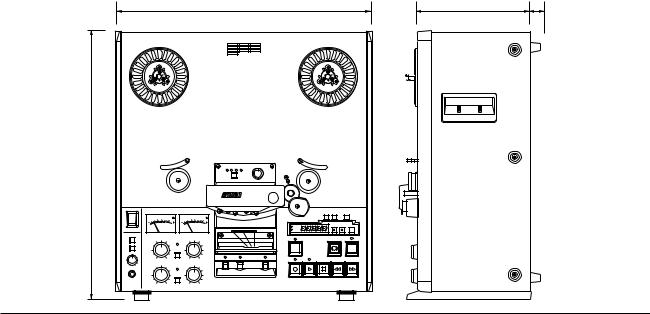
Dimensions (W x D x H) |
|
430 x 455 x 250mm (16.9" x 7.3" x 17.1") |
|
|
||||||||||
|
|
|
|
430 |
|
|
|
|
|
|
|
186 |
28 |
|
|
|
|
|
|
|
|
|
|
|
|
|
|
|
|
|
|
|
|
|
|
|
|
|
|
|
|
|
|
|
450
May 1991 |
1 - 5 |

Section 1 Introduction |
MX-50II Operation and Maintenance Manual |
1.3.4 |
Accessories |
|
Standard Accessory |
NAB Hub Reel Hold Down Knob |
2 pcs |
|
Power Cable |
1 pc |
|
Fuse 2A |
1 pc |
|
Fuse 3A |
1 pc |
|
Fuse 4A |
1 pc |
|
Fuse 5A |
1 pc |
|
Time Lag Fuse |
2 pcs |
|
Lubrication Oil |
1 pc |
|
Operation Manual |
1 pc |
Optional Accessory |
Transport Remote Control Unit |
CB-127-S |
|
Mono Head Kit |
KH-43X-S |
|
Scissors |
SB-12X |
|
Scissors (Reverse cut angle) |
SB-13D-S |
|
10.5" NAB Reel |
ZA-51A |
|
11.2" DIN Reel |
ZA-5EG |
|
Rack Mount 19" Rack Adapter |
ZA-5EK |
|
VEM Unit |
ZA-5EL |
|
Pedestal (Stand) |
ZA-5ET |
|
Input Transformer |
ZA-5EY |
|
Output Transformer |
ZA-5EZ |
|
Proximity Sensor |
SR-21F-S |
1 pc for MX-50II-N PZ9E003 OS3-322
CB-127
for MX-50II-D for MX-50II-D
Otari reserves the right to change specifications without notice or obligation.
1 - 6 |
January 1992 |

Section 2 Installation
This section contains the necessary information for unpacking, inspecting, and installing the MX-50II, and includes procedures for customizing the MX50II.
2.1 Unpacking and Inspection . . . . . . . . . . . . . . . . . . . . . . . . . . . . . . . . . . . . . . . . . . 2-2
2.2 Connecting the MX-50II . . . . . . . . . . . . . . . . . . . . . . . . . . . . . . . . . . . . . . . . . . . . . 2-3
May 1991 |
2 - 1 |

Section 2 Installation |
MX-50II Operation and Maintenance Manual |
2.1Unpacking and Inspection
Uncrating the Machine: We recommend that you open the carton carefully and retain the packing materials at least until proper operation of the machine has been established.
When sending the machine back to Otari or to your Otari dealer, follow the packing instructions printed on the carton.
CAUTION: The MX-50II weighs approximately 25 kg (55 lb.). Although uncrating and installation can be done by one person, it is recommended that you do these procedures with another person.
The carton contains the following standard accessories:
Table 2-1
Standard Accessories
REAR COVER
CONTROL PCB ASSY
_________________________________________________________________
Item |
Part No. |
Q'ty |
Notes |
_________________________________________________________________ |
|||
Reel Clamper |
KW0HV |
1 set |
|
Power Cord |
PZ9D003 |
1 |
for MX-50II-N |
Power Cord |
PZ9D229 |
1 |
for MX-50II-D |
Time Lag Fuse |
FH9-018 |
1 |
|
Time Lag Fuse 3.15A |
FH9-020 |
1 |
for MX-50II-D |
Fuse 2A |
FH7F020 |
1 |
5 x 20 mm |
Fuse 3A |
FH7F030 |
1 |
5 x 20 mm |
Fuse 4A |
FH7F040 |
1 |
5 x 20 mm |
Fuse 5A |
FH7F050 |
1 |
5 x 20 mm |
Lubrication Oil |
PZ9E003 |
1 |
for capstan motor bearing |
Operation Manual |
OS3--322 |
1 |
|
M4 x 6 Screw |
——— |
4 |
for re-attaching bottom cover after removing bottom feet |
_________________________________________________________________
Inspection: Before making any electrical connections, inspect the machine visually. If there is any evidence of damage due to rough handling during transportation, a claim should be filed with the transportation company. Do not connect or operate the MX-50II until the inspection has been completed, and any damage identified and corrected if necessary.
Customizing your MX-50II: Some of the operating methods can be changed according to your preferences.
1.Remove the rear cover by removing the four screws on the top of the machine, the upper rear feet, and the two screws above the slanted portion of the rear cover. Refer to Figure 2-1.
2.Loosen the two screws at the top of CONTROL PCB ASSEMBLY and hinge it down to horizontal.
3.Change the settings of the DIP switch on CONTROL PCB ASSEMBLY if necessary. Refer to Table 2-2.
Figure 2-1
Opening the Transport Rear Cover
2 - 2 |
June 1996 |
MX-50II Operation and Maintenance Manual |
|
|
Section 2 Installation |
|
|
|
|
Table 2-2 |
|
|
|
DIP Switch Functions |
________________________________________________________________ |
||
|
|||
|
Switch |
Function |
Factory Setting |
|
________________________________________________________________ |
||
|
SW1-1 |
Punch In (How to enter RECORD mode) |
off |
|
ON |
Press RECORD when in PLAY MODE. |
|
|
off |
While Holding RECORD down, press PLAY. |
|
|
SW1-2 |
Punch Out (How to leave RECORD without stopping the transport) |
off |
|
ON |
Press PLAY. |
|
|
off |
While holding RECORD down, press STOP. |
|
|
SW1-3 |
Speed Pair Selection |
off |
|
ON |
Low Speed Pair = 7.5 and 3.75 ips. |
|
|
off |
High Speed Pair = 15 and 7.5 ips. |
|
|
SW1-4 |
Vari Speed During Record mode. |
ON |
|
ON |
EXT and VARI SPEED MODES cannot be entered during RECORD MODE. |
|
|
off |
EXT and VARI SPEED MODES can be entered while in RECORD MODE. |
|
|
SW2 |
Fader Control Logic Level Selection (MX-50II-D Only) |
M |
|
M |
Make (Normally open) contact closure, or logic level active low. |
|
|
B |
Brake (Normally closed) contact closure, or logic level active high. |
|
|
________________________________________________________________ |
||
NOTE: Turn off the power to the MX-50II whenever changing the setting of SW1 or SW2. The change of setting does not take effect until the power is turned back on.
Please refer to Appendix for more information about operating the MX-50II at 3.75 ips.
2.2Connecting the MX-50II
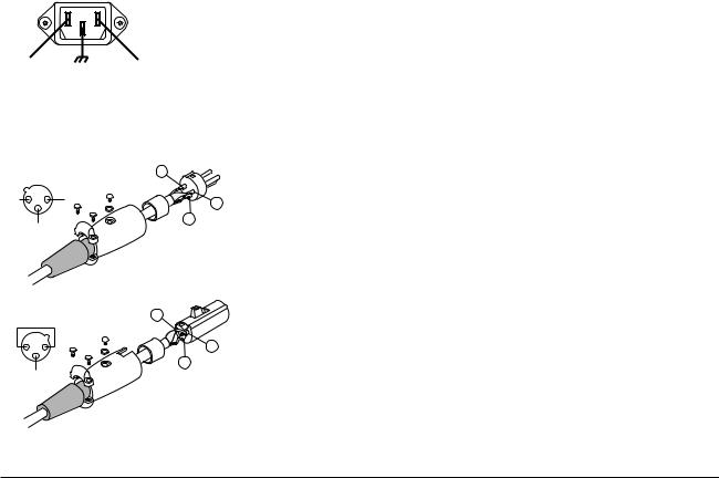
Power Connection: Insure that the voltage and frequency supplied to the machine agree with the machine's power requirement printed on the label on the connector panel or on the carton. Make sure that the MX-50II POWER
AC |
|
AC |
HOT |
GND |
NEUTRAL |
Figure 2-2
switch is turned off then connect the supplied power cord from the AC mains to the machine.
Power Connector Pin Assignment
Connecting the Audio Signal: The audio inputs to the MX-50II are balanced. The outputs are unbalanced.
BALANCED INPUT |
2 |
|
|
||
2 |
1 GND |
1 |
COLD |
|
|
|
|
|
|
3 |
3 |
|
|
|
|
HOT |
|
UNBALANCED OUTPUT 1
 GND
GND
1 |
2 |
2 |
3
3
Figure 2-3
Audio Connector Wiring (MX-50II-N)
INPUT CONNECTORS of the MX-50II-N are wired as follows:
Pin 1 = Shield (GND), Pin 2 = Cold, Pin 3 = Hot.
OUTPUT CONNECTORS of the MX-50II-N are wired as follows:
Pin 1 = GND, Pin 2 = GND, Pin 3 = Hot.
INPUT CONNECTORS of the MX-50II-D are wired as follows:
Pin 1 = Shield (GND), Pin 2 = Hot, Pin 3 = Cold.
OUTPUT CONNECTORS of the MX-50II-D are wired as follows: Pin 1 = GND, Pin 2 = Hot, Pin 3 = GND.
May 1991 |
2 - 3 |

Section 2 Installation |
MX-50II Operation and Maintenance Manual |
Connector Pin Assignments
Table 2-3
REMOTE Connector Pin Assignment
_______________________________ ________________________________
No. |
Description |
Level |
I/O |
No. |
Description |
Level |
I/O |
||
_______________________________ |
________________________________ |
||||||||
1. |
RECORD Switch |
Low |
In |
|
20. |
Capstan Spd Control Clock (*2) |
— |
In |
|
2. |
PLAY Switch |
Low |
In |
|
21. |
Tape Speed A (*3) |
H/L |
Out |
|
3. |
STOP Switch |
Low |
In |
|
22. |
Tape Speed B (*3) |
H/L |
Out |
|
4. |
F.FWD Switch |
Low |
In |
|
23. |
External Pitch Control Enable |
Low |
In |
|
5. |
REWIND Switch |
Low |
In |
|
24. |
NC |
— |
— |
|
6. |
Lifter Switch |
Low |
In |
|
25. |
NC |
— |
— |
|
7. |
NC |
|
— |
— |
|
26. |
NC |
— |
— |
8. |
NC |
|
— |
— |
|
27. |
NC |
— |
— |
9. |
Safety Switch Shut off |
Low |
Out |
|
28. |
NC |
— |
— |
|
10. |
Record Mode Tally |
Low |
Out |
|
29. |
NC |
— |
— |
|
11. |
Play Mode Tally |
Low |
Out |
|
30. |
NC |
— |
— |
|
12. |
Stop Mode Tally |
Low |
Out |
|
31. |
NC |
— |
— |
|
13. |
F.FWD Mode Tally |
Low |
Out |
|
32. |
NC |
— |
— |
|
14. |
REWIND Tally |
Low |
Out |
|
33. |
+5V ±10% Reg. Power Supply (max 150 mA) |
|||
15. |
NC |
|
— |
— |
|
34. |
24–40V Unreg. Power Supply (max 500 mA) |
||
16. |
Signal Ground |
|
|
|
35. |
24–40V Unreg. Power Supply (max 500 mA) |
|||
17. |
Tach. Pulse (*1, 9) |
|
Out |
|
36. |
Power Ground |
|
|
|
18. |
Tape Direction (Fwd=Low) |
H/L |
Out |
|
37. |
Power Ground |
|
|
|
19. |
NC |
|
— |
— |
|
________________________________ |
|||
_______________________________ |
|||||||||
NOTES: 1 |
Tach Pulse Rate (pulse/s) |
3.75 ips = 30, |
7.5 ips = 60, 15 ips = 120 |
|
|
||||
|
2 |
Capstan Control Freq. |
9.6 kHz = nominal tape speed. |
|
|
||||
|
|
|
Acceptable external frequency range = 4.8–19.2 kHz |
|
|
||||
|
3 |
Tape Speed Definition |
3.75 ips |
Speed A = Low, |
Speed B = Low |
|
|
||
|
|
|
7.5 ips |
Speed A = Low, |
Speed B = High |
|
|
||
|
|
|
15 ips |
|
Speed A = High, |
Speed B = Low |
|
|
|
|
4 |
Connector Type |
D-sub 37 pin (female) |
|
|
|
|||
|
5 |
Output Signals |
Output Type = Open Collector |
|
|
||||
|
|
|
VOL = 0–0.5 V, |
IOL = 20 mA (max), VIL = TTL Level |
|
|
|||
|
|
|
Leakage Current = 20 µ A |
|
|
|
|||
|
|
|
Pull Up = 10 kΩ (terminated to +5 V) |
|
|
||||
|
|
|
VOH (High Level) = +30 V (max) |
|
|
||||
|
6 |
Input Signals |
Fan-in = 1.5 |
|
|
|
|
||
|
|
|
VIL = 0–0.5 V (2.4 mA), |
VIH = 2.5–5.25 V (60 µ A) |
|
|
|||
|
7 |
Cable Length: |
max 10 m (32 feet) |
|
|
|
|||
|
8 |
Input Command Pulse: |
100 ms (min) |
|
|
|
|
||
|
9 |
Tach Pulse: |
50 µ s (min) |
|
|
|
|
||
|
10 Capstan Clock Duty Cycle: |
40–60% |
|
|
|
|
|
||
Table 2-4
FADER Connector Pin Assignment (Only MX-50II-D models)
____________________________
No. |
Description |
I/O |
____________________________ |
||
1. |
Fader Play Switch |
In |
3. |
Repro Contact* |
Out |
6. |
Signal Ground |
— |
8. |
Repro Contact* |
Out |
9. |
Frame Ground |
— |
____________________________
NOTE: To enter PLAY, connect pin 1 to pin 6. Pins 3 and 8 are closed when in REPRO MODE.
2 - 4 |
May 1991 |
Section 3 Controls and Indicators
This section describes the controls, indicators, and connectors on the MX50II tape recorders.
3.1 Transport Control Panel . . . . . . . . . . . . . . . . . . . . . . . . . . . . . . . . . . . . . . . . . . . . . 3-2
3.2 Connector Panel . . . . . . . . . . . . . . . . . . . . . . . . . . . . . . . . . . . . . . . . . . . . . . . . . . . . . . 3-8
May 1991 |
3 - 1 |

Section 3 Controls and Indicators |
MX-50II Operation and Maintenance Manual |
3.1 Transport Control Panel
POWER
1
MONITOR
2
1
3
2
PHONES
4
Figure 3-1
Transport Control Panel — 1
[1]POWER SWITCH
[2]MONITOR LEVEL KNOB
[3] MONITOR CHANNEL SELECT BUTTONS
[4] PHONES CONNECTOR
FIX VARI EXT VEM |
DOWN |
UP |
|
|
|
|
5 |
|
|
|
|
|
|
|
|
|
1 |
|
|
|
|
|
2 |
|
|
|
20 10 |
6 |
3 |
10 |
1 |
PEAK |
20 10 |
6 |
3 |
10 |
1 |
PEAK |
2 3 |
2 3 |
||||||||||
|
|
VU |
|
|
|
|
|
VU |
|
|
NAB |
|
|
|
|
|
|
|
|
|
|
|
IEC |
H
INPUT |
INPUT |
|
|
|
|
SRL |
|
|
FADER |
|
|
|
|
|
|
1 |
READY |
2 |
TAPE |
|
|
SAFE |
|
INPUT |
OUTPUT |
OUTPUT |
|
|
|
|
SRL |
|
|
|
6 |
7 |
6 |
8 |
9 |
Pressing the upper portion of this switch causes power to be applied to the machine.
This control adjusts the level of the signal at PHONES CONNECTOR [4] or built-in
MONITOR SPEAKER [32].
These buttons select the channel or channels to be sent to PHONES CONNECTOR [4] or built-in MONITOR SPEAKER [32]. Pressing CHANNEL 1 BUTTON selects channel 1 for monitoring, pressing CHANNEL 2 BUTTON selects channel 2. One or both buttons may be pressed at any time.
This 1/4" tip-ring-sleeve phone jack provides signal output for headphones having input impedance of 8 Ω or greater. Connecting the headphone to this connector cuts off the signal to MONITOR SPEAKER [32].
3 - 2 |
May 1991 |

MX-50II Operation and Maintenance Manual |
Section 3 Controls and Indicators |
|
|
[5] VU METERS |
Each VU METER incorporates a PEAK INDICATOR which illuminates when the signal |
|
reaches a level equivalent to 1040 nWb/m. |
[6] INPUT AND OUTPUT LEVEL CONTROLS |
These controls adjust the line input and output levels. When SRL SWITCH [7] |
|
associated with INPUT or OUTPUT LEVEL CONTROLS is pressed, and its indicator |
|
illuminated, the corresponding level controls have no effect. |
[7] SRL SWITCHES AND INDICATORS |
When one of these switches is pressed, the “0 VU” indication on VU METER [5] |
|
corresponds to the reference flux level (SRL: Standard Reference Level). |
[8] READY/SAFE SWITCHES AND READY INDICATORS Setting one or both of these switches to “READY” places the corresponding channel(s) into RECORD READY MODE, in which the input(s) to the channel(s) will be recorded on the tape when the transport is placed into RECORD MODE. Setting this switch to “READY” while the MX-50II is in PLAY MODE places the channel in RECORD MODE immediately.
Setting one or both of switches to “SAFE” places the corresponding channel(s) into SAFE MODE, in which recording cannot take place. Setting either READY/SAFE SWITCH to “SAFE” while the MX-50II is in RECORD MODE causes that channel to leave RECORD MODE immediately.
READY INDICATOR flashes when the channel is in RECORD READY MODE, and becomes steadily illuminated when the channel is in RECORD MODE.
[9] INPUT/TAPE SWITCH AND TAPE INDICATOR This switch selects the machine output and monitor signals. When the switch is set to “INPUT”, the signal at that channel's OUTPUT CONNECTOR is the signal present at that channel's INPUT CONNECTOR. When the switch is set to “TAPE”, the signal at that channel's OUTPUT CONNECTOR is the signal present on tape reproduced by that channel's reproduce head. TAPE INDICATOR will be illuminated.
May 1991 |
3 - 3 |
Section 3 Controls and Indicators |
MX-50II Operation and Maintenance Manual |
|
|
|
|
|
|
|
|
13 |
|
|
10 |
11 |
|
||
|
|
2 |
|
|
|
|
|
|
REEL SIZE |
SUP |
T.UP |
|
TAPE SPEED |
|
|
|
|
3 |
|
|
|
|
|
|
S |
|
|
|
|
LO |
|
|
6 |
PEAK |
|
|
|
|
|
L |
|
|
|
|
HI |
|
|
10 |
10 1 2 3 |
|
|
|
|
|
|
|
|
|
|
||||
|
|
|
|
|
|
|
|
|
|
|
|
||||
|
|
VU |
|
|
|
12 |
NAB |
|
|
|
|
ZERO |
CUE |
CLEAR |
|
|
|
|
|
|
|
IEC |
|
|
|
|
|
|
|
|
|
|
|
|
|
|
|
|
|
H |
M |
|
S |
|
|
|
14 |
|
INPUT |
|
|
|
|
|
|
|
|
|
|
|
|||
|
|
|
|
|
|
15 |
FADER |
16 |
|
|
|
|
EDIT |
17 |
|
|
|
|
|
|
|
|
|
|
|
|
|
|
|
||
|
|
|
1 |
READY |
2 |
TAPE |
|
|
|
|
|
|
|
|
|
|
|
|
|
SAFE |
|
INPUT |
|
|
|
|
|
|
|
|
|
|
OUTPUT |
|
|
|
|
|
|
|
|
|
|
|
|
||
|
|
|
|
|
|
|
18 |
19 |
|
20 |
21 |
22 |
|
||
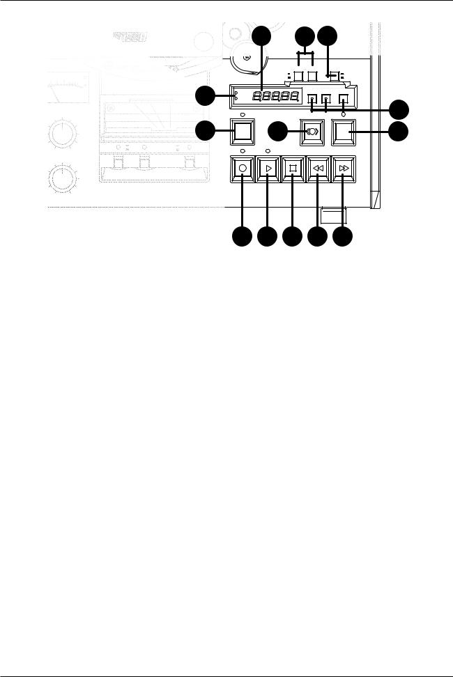
Figure 3-2
Transport Control Panel — 2
[10] |
REEL SIZE S/L KEY |
Selects the tape tension to match the reel size being used. |
[11] |
TAPE SPEED LO/HI KEY |
Pressing this key causes the tape speed to change. |
[12] |
NAB AND IEC INDICATORS |
Indicates the current position of EQUALIZATION IEC/NAB SWITCH [38] on the connector |
|
|
panel. |
[13] |
TAPE TIMER |
Displays the current tape location as Hours, Minutes, and Seconds. |
[14] |
SEARCH ZERO, CUE AND CLEAR KEYS |
Pressing SEARCH ZERO KEY places the transport into SEARCH ZERO MODE. |
|
|
SEARCH CUE KEY is used to store and/or initiate a search to a stored tape location. |
Pressing CLEAR KEY together with another key clears TAPE TIMER [13] or the memory associated with that key.
CLEAR + SEARCH ZERO resets TAPE TIMER to 0.00.00.
CLEAR + SEARCH CUE clears stored cue point memory.
3 - 4 |
May 1991 |

MX-50II Operation and Maintenance Manual |
Section 3 Controls and Indicators |
|
|
|
|
[15] |
FADER BUTTON AND INDICATOR* |
Pressing this button enables the fader start line on FADER CONNECTOR [35] on the |
|
|
connector panel. When the fader start function is enabled, PLAY and STOP BUTTONS |
|
|
on the transport are disabled. *(MX-50D Only) |
[16] |
CUE BUTTON AND INDICATOR |
Pressing this button during FAST WIND MODES initiates CUE MODE, in which the |
|
|
tape lifters retract allowing the tape to be in contact with the reproduce head |
|
|
for audio monitoring at wind speed. |
|
|
Holding CUE BUTTON pressed causes the tape lifters to remain retracted as |
|
|
long as the button is held pressed. Tapping CUE BUTTON quickly causes the |
|
|
lifters to remain retracted until the next time CUE BUTTON is pressed. |
[17] |
EDIT BUTTON AND INDICATOR |
Pressing this button while in STOP MODE causes the MX-50II to enter EDIT |
|
|
READY MODE, in which the take-up motor is turned off, the safety switch for the |
|
|
supply swing arm is deactivated, and EDIT INDICATOR flashes. Pressing PLAY BUTTON |
|
|
while in EDIT READY MODE, or pressing EDIT BUTTON while in PLAY MODE, causes the |
|
|
MX-50II to enter DUMP EDIT MODE, in which the take-up reel does not rotate |
|
|
allowing tape to be “dumped” from the transport. |
|
|
NOTE: If there is slack in the tape path and the safety switch for the supply |
|
|
swing arm is deactivated, EDIT READY MODE will be activated when EDIT BUTTON is |
|
|
pressed, and DUMP EDIT MODE will start when PLAY BUTTON is pressed. |
[18] RECORD BUTTON AND INDICATOR |
Places the transport into RECORD MODE. |
|
[19] |
PLAY BUTTON AND INDICATOR |
Places the transport into PLAY MODE. Pressing this button when there is slack |
|
|
in the tape path causes the take-up reel to rotate very slowly until the slack is |
|
|
removed, then the transport enters PLAY MODE. |
[20] |
STOP BUTTON |
Pressing this button when the transport is in RECORD, PLAY, DUMP EDIT, FAST |
|
|
FORWARD, or REWIND MODE causes the tape motion to stop. |
[21] REWIND BUTTON |
Places the transport into REWIND MODE, in which the tape moves from the |
|
|
|
take-up reel to the supply reel at fast wind speed. |
[22] |
F.FWD BUTTON |
Places the transport into FAST FORWARD MODE, in which the tape moves from |
|
|
the supply reel to the take-up reel at fast wind speed. |
May 1991 |
3 - 5 |

Section 3 Controls and Indicators |
|
|
|
|
|
|
|
|
|
|
|
MX-50II Operation and Maintenance Manual |
||||
|
|
|
|
|
|
|
|
|
|
|
|
|
|
|
|
|
|
|
|
|
|
|
|
|
|
|
|
|
|
|
|
|
|
|
|
|
|
|
|
|
|
|
|
|
|
|
|
|
|
|
|
|
|
|
|
|
|
|
|
|
|
|
|
|
|
|
|
|
|
|
|
|
|
|
|
|
|
|
|
|
|
|
|
|
|
|
|
|
|
|
|
|
|
|
|
|
|
|
|
|
|
|
|
|
|
|
|
|
|
|
|
|
|
|
|
|
|
|
|
|
|
|
|
|
|
|
|
|
|
|
|
|
|
|
|
|
|
|
|
|
|
|
|
|
|
|
|
|
|
|
|
|
|
|
|
|
|
|
|
|
|
|
|
|
|
|
|
|
|
|
|
|
|
|
|
|
|
|
|
|
|
|
|
|
|
|
|
|
|
|
|
|
|
|
|
|
|
|
|
|
|
|
|
|
|
|
|
|
|
|
|
|
|
|
|
|
|
|
|
|
|
|
|
|
|
|
|
|
|
|
|
|
|
|
|
|
|
|
|
|
|
|
|
|
|
|
|
|
|
|
|
|
|
|
32 |
|
|
31 |
|
31 |
30 |
|
30 |
23 |
|
24 |
FIX VARI EXT VEM |
DOWN |
UP |
|
||
28 |
|
29 |
POWER |
|
1 |
|
|
|
|
|
2 |
|
|
|
20 10 |
6 |
3 |
10 |
1 |
PEAK |
20 10 |
6 |
3 |
10 |
1 |
PEAK |
2 3 |
2 3 |
||||||||||
|
|
VU |
|
|
|
|
|
VU |
|
|
|
MONITOR |
INPUT |
|
|
|
INPUT |
|
|
||||
|
|
|
|
|
|
||||||
25 |
|
REEL SIZE SUP |
T.UP |
|
TAPE SPEED |
|
S |
|
|
LO |
26 |
L |
|
|
HI |
27 |
ZERO |
CUE |
CLEAR |
S
Figure 3-3
Transport Control Panel — 3
[23] SPEED MODE BUTTON AND INDICATORS |
Repeatedly pressing this button causes the speed mode of the MX-50II to |
|
step through the four speed modes (FIX, VARI, EXT, VEM) in the sequence (if |
|
the optional VEM PCB ASSEMBLY is not installed, VOICE EDIT MODE cannot be selected). |
|
In FIX SPEED MODE, the capstan motor speed is controlled by the internal |
|
crystal oscillator. |
|
In VARI SPEED MODE, the tape speed is controlled by PITCH CONTROL KNOB [24]. |
|
In EXT SPEED MODE, the tape speed is controlled by the external speed |
|
reference signal connected to REMOTE CONNECTOR [34] on the rear panel. If the |
|
speed mode is set to EXT, and the PITCH ENABLE line (Pin 23 on REMOTE |
|
CONNECTOR) is not activated, FIX INDICATOR will remain illuminated, and EXT INDICATOR |
|
will flash. Set the speed mode to EXT when using a synchronizer or |
|
resolver to control the MX-50II. Refer to §2.2 for additional information |
|
about controlling the tape speed using an external controller. |
|
In VOICE EDIT MODE (VEM), the tape is reproduced at two times the |
|
currently selected speed, but the pitch of the signal remains constant. |
|
If SW1-4 on CONTROL PCB ASSEMBLY is “ON”, the MX-50II cannot enter VARI or |
|
EXT SPEED MODES when in RECORD MODE. |
3 - 6 |
May 1991 |
Loading...