


Part No. OS3-298
Lot: E
MX-5050 MKIV-2, BIII-2
MASTER TAPE RECORDER
OPERATION AND MAINTENANCE MANUAL
FOURTH EDITION
Printed: Dec 1997
Ed 4 (MA)

Copyright © 1992, 1997 Otari, Inc. and Otari Corporation
Printed in Japan
This manual may not be reproduced by any means without written permission.

CAUTION
To prevent fire or shock hazard:
Do not expose this unit to rain or moisture.
Do not remove panels (unless instructed to do so).
There are no user-serviceable parts inside.
Refer servicing to qualified service personnel.
PLEASE READ THROUGH THE SAFETY INSTRUCTIONS ON THE NEXT PAGE.
|
|
SAFETY INSTRUCTIONS |
1. |
Read Instructions |
All the safety and operating instructions should be read before the device is |
|
|
operated. |
2. |
Retain Instructions |
The safety and operating instructions should be retained for future. |
3. |
Heed Warnings |
All warnings on the device and in the operating instructions should be |
|
|
adhered to. |
4. |
Follow Instructions |
All operating and use instructions should be followed. |
5. |
Water and Moisture |
The device should not be used near water — for example, near bathtub, wash |
|
|
bowl, kitchen sink, laundry tub, in a wet basement, or near a swimming pool, |
|
|
etc. |
6. |
Carts and Stands |
The device should be used only with a cart or stand that is recommended by |
|
|
the manufacturer. |
7. |
Ventilation |
The device should be situated so that its location or position does not interfere |
|
|
with its proper ventilation. For example, the device should not be situated on a |
|
|
bed, sofa, rug, or similar surface that may block the ventilation openings; or, |
|
|
placed in a built-in installa-tion, such as a bookcase or cabinet that may impede |
|
|
the flow of air through the ventilation openings. |
8. |
Heat |
The device should be situated away from heat sources such as radiator, heat |
|
|
registers, stoves or other appliances (including amplifiers) that produce heat. |
9. |
Power Sources |
The device should be connected to a power supply only of the type described |
|
|
in the operating instructions or as marked on the device. |
10. |
Grounding or Polarization |
Precautions should be taken so that the grounding or polariza-tion means of |
|
|
the device is not defeated. |
11. |
Power Cord Protection |
Power supply cords should be routed as they are not likely to be walked on |
|
|
or pinched by items placed upon or against them, paying particular attention |
|
|
to cords at plugs, convenience recep-tacles, and the point where they exit |
|
|
from the device. |
12. |
Cleaning |
The device should be cleaned only as recommended by the manufacturer. |
13. |
Non-Use Periods |
The power cord of the device should be unplugged from the out-let when left |
|
|
unused for a long period of time. |
14 |
Object and Liquid Entry |
Care should be taken so that objects do not fall and that liquids are not |
|
|
spilled into the enclosure through openings. |
15. |
Damage Requiring Service |
The device should be serviced by qualified service personnel when: |
|
|
A. The power-supply cord or the plug has been damaged; or |
|
|
B. Objects have fallen, or liquid has been spilled into the appliance; or |
|
|
C. The appliance has been exposed to rain; or |
|
|
D. The appliance does not appear to operate normally or exhibits marked |
|
|
change in performance; or |
|
|
E. The appliance has been dropped, or the enclosure damaged. |
16. |
Servicing |
The user should not attempt to service the device beyond that described in |
|
|
the operating instructions. All other service should be referred to qualified |
|
|
personnel. |
iv
COMMUNICATION WITH OTARI
FOR SERVICE INFORMATION AND PARTS
All Otari products are manufactured under strict quality control. Each unit is carefully inspected and tested prior to shipment.
If, however, some adjustment or technical support becomes necessary, replacement parts are required, or technical questions arise, please contact your Otari dealer or contact Otari at:
Otari, Inc. |
|
Otari Corporation |
|
4-33-3 Kokuryocho, Chofu-shi, |
8236 Remmet Ave. |
||
182-0022, Tokyo, Japan |
Canoga Park, CA 91304 |
||
Phone |
: (81) 42481-8626 |
U.S.A. |
|
Fax |
: (81) 42481-8633 |
Phone |
: (818) 594-5908 |
|
|
Fax |
: (818) 594-7208 |
Otari Europe GmbH. |
|
|
Otari Singapore Pte., Ltd |
|
Rudolf-Diesel-Straße 12 |
40 MacTaggart Road |
|||
D-40670 Meerbusch 2 (Osterath) |
Singapore 368085 |
|||
Germany |
|
|
Phone |
: (65) 284-7211 |
Phone |
: (49) |
2159-50861 |
Fax |
: (65) 284-4727 |
Fax |
: (49) |
2159-1778 |
|
|
Another part of Otari’s continuing technical support program for our products is the continuous revision of manuals as the equipment is improved or modified. In order for you to receive the information and support which is applicable to your equipment, and for the technical support program to function properly, please include the following information, most of which can be obtained from the Serial number label on the machine, in all correspondence with Otari:
•Model Number:
•Serial Number:
•Date of Purchase:
•Name and address of the dealer where the machine was purchased and the power requirements (voltage and frequency) of the machine.
v

Table of Contents
Safety Instructions . . . . . . . . . . . . . . . . . . . . . . . . . . . . . . . . . . . . . . . . . . . . . . . . . . . . . . . . . . v
Communication with Otari . . . . . . . . . . . . . . . . . . . . . . . . . . . . . . . . . . . . . . . . . . . . . . . . vii
Section 1 Introduction
1.1 |
MX-5050 Series . . . . . . . . . . . . . . . . . . . . . . . . . . . . . . . . . . . . . . . . . . . . . . . . . . . . . |
1-2 |
1.2 |
Using This Manual . . . . . . . . . . . . . . . . . . . . . . . . . . . . . . . . . . . . . . . . . . . . . . . . . . |
1-3 |
|
1.2.1 Organization . . . . . . . . . . . . . . . . . . . . . . . . . . . . . . . . . . . . . . . . . . . . . . . . . . . . . . |
1-3 |
|
1.2.2 Conventions within this manual . . . . . . . . . . . . . . . . . . . . . . . . . . . . . . . . . . . |
1-4 |
Section 2 Installaion
2.1 Unpacking and Inspection . . . . . . . . . . . . . . . . . . . . . . . . . . . . . . . . . . . . . . . . . 2-2
2.2 Audio Signal Connection . . . . . . . . . . . . . . . . . . . . . . . . . . . . . . . . . . . . . . . . . . 2-3
2.2.1 Audio Connectors . . . . . . . . . . . . . . . . . . . . . . . . . . . . . . . . . . . . . . . . . . . . . . . . . 2-3
2.2.2 Balance/Unbalance Adjustment . . . . . . . . . . . . . . . . . . . . . . . . . . . . . . . . . . . . 2-4
2.3 Switch Position Adjustment . . . . . . . . . . . . . . . . . . . . . . . . . . . . . . . . . . . . . . . 2-5
2.4 PCB Assembly Location . . . . . . . . . . . . . . . . . . . . . . . . . . . . . . . . . . . . . . . . . . . 2-9
2.4.1 MX-5050 BIII . . . . . . . . . . . . . . . . . . . . . . . . . . . . . . . . . . . . . . . . . . . . . . . . . . . . . 2-9 2.4.2 MX-5050 MKIV2 . . . . . . . . . . . . . . . . . . . . . . . . . . . . . . . . . . . . . . . . . . . . . . . . . . 2-11
2.5 Power Connection . . . . . . . . . . . . . . . . . . . . . . . . . . . . . . . . . . . . . . . . . . . . . . . . . 2-13
2.6 Fuse Replacement . . . . . . . . . . . . . . . . . . . . . . . . . . . . . . . . . . . . . . . . . . . . . . . . . . 2-14
2.7 Speed Conversion (BIII-2) . . . . . . . . . . . . . . . . . . . . . . . . . . . . . . . . . . . . . . . . . 2-15
2.8 Equalizer Change . . . . . . . . . . . . . . . . . . . . . . . . . . . . . . . . . . . . . . . . . . . . . . . . . . . 2-15
Section 3 Controls and Indicators
3.1 Tape Transport . . . . . . . . . . . . . . . . . . . . . . . . . . . . . . . . . . . . . . . . . . . . . . . . . . . . . . 3-2
3.2 Transport Control Panel . . . . . . . . . . . . . . . . . . . . . . . . . . . . . . . . . . . . . . . . . . . 3-3
3.3 Head Assembly . . . . . . . . . . . . . . . . . . . . . . . . . . . . . . . . . . . . . . . . . . . . . . . . . . . . . 3-6
3.4 Amplifier Panel . . . . . . . . . . . . . . . . . . . . . . . . . . . . . . . . . . . . . . . . . . . . . . . . . . . . . . 3-7
3.5 Audio Connector Panel . . . . . . . . . . . . . . . . . . . . . . . . . . . . . . . . . . . . . . . . . . . 3-9
3.6 Connector Pin Assignments . . . . . . . . . . . . . . . . . . . . . . . . . . . . . . . . . . . . . 3-12
Section 4 Operation
4.1 Operation Mode Reference Tables . . . . . . . . . . . . . . . . . . . . . . . . . . . . . . . . 4-2
4.2 Modes of Operation . . . . . . . . . . . . . . . . . . . . . . . . . . . . . . . . . . . . . . . . . . . . . . . . 4-3
4.2.1 Transport Modes . . . . . . . . . . . . . . . . . . . . . . . . . . . . . . . . . . . . . . . . . . . . . . . . . 4-3
4.2.2 Audio Channel Modes . . . . . . . . . . . . . . . . . . . . . . . . . . . . . . . . . . . . . . . . . . . . . 4-4
May 1992 |
vii |

Table of Contents MX-5050 Operation and Maintenance Manual
4.3 |
Operating the MX-5050 . . . . . . . . . . . . . . . . . . . . . . . . . . . . . . . . . . . . . . . . . . . |
. 4-5 |
|
4.3.1 Placing Reels on the Machine . . . . . . . . . . . . . . . . . . . . . . . . . . . . . . . . . . . . . |
4-5 |
|
4.3.2 Threading the Tape . . . . . . . . . . . . . . . . . . . . . . . . . . . . . . . . . . . . . . . . . . . . . . . |
4-6 |
4.4 |
Operation of the Transport . . . . . . . . . . . . . . . . . . . . . . . . . . . . . . . . . . . . . . . . |
4-7 |
|
4.4.1 Playing Back the Tracks . . . . . . . . . . . . . . . . . . . . . . . . . . . . . . . . . . . . . . . . . . . |
4-7 |
|
4.4.2 Recording the Tracks . . . . . . . . . . . . . . . . . . . . . . . . . . . . . . . . . . . . . . . . . . . . . |
4-7 |
|
4.4.3 SEL-REP Recording . . . . . . . . . . . . . . . . . . . . . . . . . . . . . . . . . . . . . . . . . . . . . . . . |
4-8 |
|
4.4.4 Fast Wind and CUE Monitor . . . . . . . . . . . . . . . . . . . . . . . . . . . . . . . . . . . . . . . . |
4-8 |
|
4.4.5 Tape Editing . . . . . . . . . . . . . . . . . . . . . . . . . . . . . . . . . . . . . . . . . . . . . . . . . . . . . . |
4-9 |
|
4.4.6 Using the Pitch Control Feature . . . . . . . . . . . . . . . . . . . . . . . . . . . . . . . . . . |
4-10 |
4.5 |
Locator Operation . . . . . . . . . . . . . . . . . . . . . . . . . . . . . . . . . . . . . . . . . . . . . . . . . |
4-11 |
|
4.5.1 Storing Tape Locations . . . . . . . . . . . . . . . . . . . . . . . . . . . . . . . . . . . . . . . . . . |
4-11 |
|
4.5.2 Search Mode . . . . . . . . . . . . . . . . . . . . . . . . . . . . . . . . . . . . . . . . . . . . . . . . . . . . |
4-11 |
|
4.5.3 Search Play Mode . . . . . . . . . . . . . . . . . . . . . . . . . . . . . . . . . . . . . . . . . . . . . . . |
4-12 |
|
4.5.4 Search Zero Mode . . . . . . . . . . . . . . . . . . . . . . . . . . . . . . . . . . . . . . . . . . . . . . . |
4-12 |
|
4.5.5 Search Start Mode . . . . . . . . . . . . . . . . . . . . . . . . . . . . . . . . . . . . . . . . . . . . . . . |
4-12 |
|
4.5.6 Repeat Mode . . . . . . . . . . . . . . . . . . . . . . . . . . . . . . . . . . . . . . . . . . . . . . . . . . . . |
4-13 |
4.6 |
Test Oscillator . . . . . . . . . . . . . . . . . . . . . . . . . . . . . . . . . . . . . . . . . . . . . . . . . . . . . . |
4-13 |
Section 5 Maintenance
5.1 Maintenance Scheduling . . . . . . . . . . . . . . . . . . . . . . . . . . . . . . . . . . . . . . . . . . 5-2
5.2 Demagnetizing . . . . . . . . . . . . . . . . . . . . . . . . . . . . . . . . . . . . . . . . . . . . . . . . . . . . . . 5-2
5.3 Cleaning the Tape Path . . . . . . . . . . . . . . . . . . . . . . . . . . . . . . . . . . . . . . . . . . . . . 5-3
5.4 Lubrication . . . . . . . . . . . . . . . . . . . . . . . . . . . . . . . . . . . . . . . . . . . . . . . . . . . . . . . . . . 5-4
Section 6 Transport Adjustment and Parts Replacement
6.1 |
Transport Access . . . . . . . . . . . . . . . . . . . . . . . . . . . . . . . . . . . . . . . . . . . . . . . . |
. . . 6-2 |
6.2 |
Brake Torque Adjustment . . . . . . . . . . . . . . . . . . . . . . . . . . . . . . . . . . . . . . |
. . . 6-2 |
6.3 |
Tape Lifter Adjustment . . . . . . . . . . . . . . . . . . . . . . . . . . . . . . . . . . . . . . . . . |
. . . 6-4 |
6.4 |
Capstan Motor Adjustment and Pitch Control Adjustment |
. . . 6-5 |
6.5 |
Pinch Roller Pressure Adjustment . . . . . . . . . . . . . . . . . . . . . . . . . . . . |
. . . 6-6 |
6.6 |
Tape Speed Adjustment . . . . . . . . . . . . . . . . . . . . . . . . . . . . . . . . . . . . . . . . |
. . . 6-8 |
6.7 |
Reel Table Height Adjustment . . . . . . . . . . . . . . . . . . . . . . . . . . . . . . . . . |
. . . 6-9 |
6.8 |
Head Assembly Replacement . . . . . . . . . . . . . . . . . . . . . . . . . . . . . . . . . |
. . 6-10 |
6.9 |
Head Position Adjustment . . . . . . . . . . . . . . . . . . . . . . . . . . . . . . . . . . . . . . |
. 6-11 |
viii |
May 1992 |

MX-5050 Operation and Maintenance Manual Table of Contents
Section 7 Audio Alignment
7.1 |
Tools and Equipment Required . . . . . . . . . . . . . . . . . . . . . . . . . . . . . . . . . . |
. 7-2 |
7.2 |
Block Diagrams . . . . . . . . . . . . . . . . . . . . . . . . . . . . . . . . . . . . . . . . . . . . . . . . . . . . . |
7-3 |
|
7.2.1 Peak Indicator Level Adjustment . . . . . . . . . . . . . . . . . . . . . . . . . . . . . . . . . . |
7-3 |
|
7.2.2 Test Oscillator Waveform and Level Adjustment . . . . . . . . . . . . . . . . . . . . . |
7-4 |
7.3 |
Reproduce Adjustments . . . . . . . . . . . . . . . . . . . . . . . . . . . . . . . . . . . . . . . . . . . |
7-5 |
|
7.3.1 Reproduce Head Azimuth Adjustment . . . . . . . . . . . . . . . . . . . . . . . . . . . . . |
7-5 |
|
7.3.2 Reproduce Level Adjustment . . . . . . . . . . . . . . . . . . . . . . . . . . . . . . . . . . . . . . |
7-6 |
|
7.3.3 Reproduce Equalization Adjustment . . . . . . . . . . . . . . . . . . . . . . . . . . . . . . . |
7-7 |
7.4 |
Record Electronics Adjustments . . . . . . . . . . . . . . . . . . . . . . . . . . . . . . . . . |
7-8 |
|
7.4.1 Record Bias Level Adjustment . . . . . . . . . . . . . . . . . . . . . . . . . . . . . . . . . . . . |
7-8 |
|
7.4.2 Record Head Azimuth Adjustment . . . . . . . . . . . . . . . . . . . . . . . . . . . . . . . . . |
7-9 |
|
7.4.3 Record Level Adjustment . . . . . . . . . . . . . . . . . . . . . . . . . . . . . . . . . . . . . . . . |
7-10 |
|
7.4.4 Record Equalization Adjustment . . . . . . . . . . . . . . . . . . . . . . . . . . . . . . . . . . . |
7-11 |
|
7.4.5 Low Frequency Reproduce Equalization Adjustment . . . . . . . . . . . . . . . . |
7-11 |
|
7.4.6 SEL-REP Level Adjustment . . . . . . . . . . . . . . . . . . . . . . . . . . . . . . . . . . . . . . . . |
7-12 |
Section 8 Specifications
8.1 Tape Transport . . . . . . . . . . . . . . . . . . . . . . . . . . . . . . . . . . . . . . . . . . . . . . . . . . . . . . 8-2
8.2 Electoronics . . . . . . . . . . . . . . . . . . . . . . . . . . . . . . . . . . . . . . . . . . . . . . . . . . . . . . . . . 8-3
Section 9 Exploded Views and
BIII . . . . . . . . . . . . . . . . . . . . . . . . . . . . . . . . . . . . . . . . . . . . . . . . . . . . . . . . . . . . . . . . . . 9-2 ~ 9-19
MKIV-2 . . . . . . . . . . . . . . . . . . . . . . . . . . . . . . . . . . . . . . . . . . . . . . . . . . . . . . . . . . . . 9-20 ~ 9-39
Appendix
Block Diagram
Troubleshooting Hints (Electronics)
Troubleshooting Hints (Transport)
Index
Schematic Diagrams
May 1992 |
ix |
List of Figures
Figure |
1-1 |
. . . . . . . . . . . . . . . . . . . . . . . . . . . . . . . . .Exterior Appearance |
. 1-2 |
Figure |
2-1 |
Audio Connectors . . . . . . . . . . . . . . . . . . . . . . . . . . . . . . . . . . . . |
2-3 |
|
2-2 |
Balanced/Unbalanced Connectors . . . . . . . . . . . . . . . . . . . . . |
2-4 |
|
2-3 |
Switch Setting on Rear Panel . . . . . . . . . . . . . . . . . . . . . . . . . . |
2-5 |
|
2-4 |
Controls on the CONTROL PCB Assembly . . . . . . . . . . . . . |
2-6 |
|
2-5 |
PCB Assembly Location (BIII) . . . . . . . . . . . . . . . . . . . . . . . . . |
2-9 |
|
2-6 |
AMP Section Rotation (BIII) . . . . . . . . . . . . . . . . . . . . . . . . . . |
2-9 |
|
2-7 |
CONTROL PCB Assembly Rotation (BIII) . . . . . . . . . . . . . |
2-10 |
|
2-8 |
PCB Assembly Location (MKIV-2) . . . . . . . . . . . . . . . . . . . . |
2-11 |
|
2-9 |
CONTROL PCB Assembly Rotation (MKIV-2) . . . . . . . . . |
2-12 |
|
2-10 |
Power Connection . . . . . . . . . . . . . . . . . . . . . . . . . . . . . . . . . . . |
2-13 |
|
2-11 |
AC Line Voltage Connector . . . . . . . . . . . . . . . . . . . . . . . . . . . . |
2-13 |
|
2-12 |
Fuse Location . . . . . . . . . . . . . . . . . . . . . . . . . . . . . . . . . . . . . . . . . |
2-14 |
Figure |
3-1 |
Tape Transport . . . . . . . . . . . . . . . . . . . . . . . . . . . . . . . . . . . . . . . |
3-2 |
|
3-2 |
Transport Control Panel . . . . . . . . . . . . . . . . . . . . . . . . . . . . . . . |
3-3 |
|
3-3 |
Head Assembly . . . . . . . . . . . . . . . . . . . . . . . . . . . . . . . . . . . . . . . |
3-6 |
|
3-4 |
Amplifier Panel (MKIV-2) . . . . . . . . . . . . . . . . . . . . . . . . . . . . . |
3-7 |
|
3-5 |
Audio Connector Panel (BIII) . . . . . . . . . . . . . . . . . . . . . . . . . . |
3-7 |
|
3-6 |
Audio Connector Panel (MKIV-2) . . . . . . . . . . . . . . . . . . . . |
3-10 |
Figure |
4-1 |
Tape Threading . . . . . . . . . . . . . . . . . . . . . . . . . . . . . . . . . . . . . . . |
4-6 |
|
4-2 |
Editing a Tape . . . . . . . . . . . . . . . . . . . . . . . . . . . . . . . . . . . . . . . |
4-10 |
Figure |
5-1 |
Demagnetizing the Head . . . . . . . . . . . . . . . . . . . . . . . . . . . . . . |
5-2 |
|
5-2 |
Cleaning the Head . . . . . . . . . . . . . . . . . . . . . . . . . . . . . . . . . . . . |
5-3 |
|
5-3 |
Lubrication . . . . . . . . . . . . . . . . . . . . . . . . . . . . . . . . . . . . . . . . . . . |
5-4 |
Figure |
6-1 |
Brake Torque Measurement . . . . . . . . . . . . . . . . . . . . . . . . . . |
6-2 |
|
6-2 |
Brake Torque Adjustment . . . . . . . . . . . . . . . . . . . . . . . . . . . . . |
6-3 |
|
6-3 |
Tape Lifter Adjustment . . . . . . . . . . . . . . . . . . . . . . . . . . . . . . . |
6-4 |
|
6-4 |
Waveform on Oscilloscope . . . . . . . . . . . . . . . . . . . . . . . . . . . |
6-5 |
|
6-5 |
Pinch Roller Pressure Measurement . . . . . . . . . . . . . . . . . . |
6-6 |
|
6-6 |
Pinch Roller Solenoid . . . . . . . . . . . . . . . . . . . . . . . . . . . . . . . . |
6-6 |
|
6-7 |
Pinch Roller Pressure Measurement . . . . . . . . . . . . . . . . . . |
6-7 |
|
6-8 |
Reel Table Height Adjustment . . . . . . . . . . . . . . . . . . . . . . . . . |
6-9 |
|
6-9 |
Head Assembly Replacement . . . . . . . . . . . . . . . . . . . . . . . . |
6-10 |
|
6-10 |
Height/Zenith Adjustment . . . . . . . . . . . . . . . . . . . . . . . . . . . |
6-11 |
|
6-11 |
Wrap Adjustment . . . . . . . . . . . . . . . . . . . . . . . . . . . . . . . . . . . . . |
6-12 |
Figure |
7-1 |
REC/REP AMP PCB Assembly. . . . . . . . . . . . . . . . . . . . . . . . . . |
7-4 |
|
7-2 |
Head Adjustment Screws . . . . . . . . . . . . . . . . . . . . . . . . . . . . . |
7-5 |
|
7-3 |
Wave Shape on the Oscilloscope . . . . . . . . . . . . . . . . . . . . . . |
7-6 |
|
7-4 |
Head Assembly . . . . . . . . . . . . . . . . . . . . . . . . . . . . . . . . . . . . . . . |
7-9 |
|
7-5 |
Waveshape on the Oscilloscope. . . . . . . . . . . . . . . . . . . . . . . . |
. 7-9 |
|
|
|
|
|
|
|
|
May 1992 |
xi |

List of Tables
Table |
2-1 |
. . . . . . . . . . . . . . . . . . . . . . . . . . . . . . . .Standard Accessories |
. 2-2 |
|
2-2 Settings on Rear Panel . . . . . . . . . . . . . . . . . . . . . . . . . . . . . . . . |
2-5 |
|
|
2-3 DIP SW Setting on the Control PCB . . . . . . . . . . . . . . . . . . . . . . |
2-6 |
|
|
2-4 |
Capstan PLL Reference. . . . . . . . . . . . . . . . . . . . . . . . . . . . . . . . . |
. 2-7 |
|
2-5 SEARCH 3 Key Function . . . . . . . . . . . . . . . . . . . . . . . . . . . . . . . . |
. 2-7 |
|
|
2-6 |
Machine Type . . . . . . . . . . . . . . . . . . . . . . . . . . . . . . . . . . . . . . . . . . |
. 2-8 |
|
2-7 |
Fuse Specifications . . . . . . . . . . . . . . . . . . . . . . . . . . . . . . . . . . . . |
2-15 |
Table |
3-1 Parallel I/O Pin Assignments . . . . . . . . . . . . . . . . . . . . . . . . . . |
3-12 |
|
|
3-2 Connector Pin 21, 22 . . . . . . . . . . . . . . . . . . . . . . . . . . . . . . . . . |
3-12 |
|
|
3-3 Remote Control Connector (MKIV-8 Option) . . . . . . . . . . |
3-13 |
|
Table |
4-1 |
Transport Modes . . . . . . . . . . . . . . . . . . . . . . . . . . . . . . . . . . . . . . |
4-2 |
|
4-2 |
Audio Channel Modes . . . . . . . . . . . . . . . . . . . . . . . . . . . . . . . . . |
4-2 |
|
4-3 |
Auto Locator Modes . . . . . . . . . . . . . . . . . . . . . . . . . . . . . . . . . . . |
4-2 |
|
4-4 |
Vari Pitch Preset . . . . . . . . . . . . . . . . . . . . . . . . . . . . . . . . . . . . . . |
4-10 |
|
4-5 Cue Point Set Mode . . . . . . . . . . . . . . . . . . . . . . . . . . . . . . . . . . . |
4-11 |
|
Table |
5-1 |
Maintenance Time Table . . . . . . . . . . . . . . . . . . . . . . . . . . . . . . . |
5-2 |
|
5-2 Tools Required for Maintenance . . . . . . . . . . . . . . . . . . . . . . . . |
. 5-2 |
|
Table |
6-1 |
Necessary Tools . . . . . . . . . . . . . . . . . . . . . . . . . . . . . . . . . . . . . . |
6-2 |
|
6-2 |
Brake Tension Values . . . . . . . . . . . . . . . . . . . . . . . . . . . . . . . . . . |
. 6-3 |
|
6-3 |
Tape Speed Settings . . . . . . . . . . . . . . . . . . . . . . . . . . . . . . . . . . . |
. 6-8 |
Table |
7-1 |
Reference Tapes . . . . . . . . . . . . . . . . . . . . . . . . . . . . . . . . . . . . . . . |
7-2 |
|
7-2 |
Trigger Level . . . . . . . . . . . . . . . . . . . . . . . . . . . . . . . . . . . . . . . . . . |
7-3 |
|
7-3 |
Overbias Values . . . . . . . . . . . . . . . . . . . . . . . . . . . . . . . . . . . . . . . |
. 7-8 |
|
|
|
|
|
|
|
|
May 1992 |
xiii |

Section 1 Introduction
This Section includes a general description of the features of the MX-5050 series tape recorders and information on the structure of this manual.
1.1 MX-5050 Series . . . . . . . . . . . . . . . . . . . . . . . . . . . . . . . . . . . . . . . . . . . . . . . . . . . . . 1-2
1.2 Using This Manual . . . . . . . . . . . . . . . . . . . . . . . . . . . . . . . . . . . . . . . . . . . . . . . . . . 1-3
1.2.1 |
Organization . . . . . . . . . . . . . . . . . . . . . . . . . . . . . . . . . . . . . . . . . . . . . . . . . . . . . . |
1-3 |
1.2.2 |
Conventions within this manual . . . . . . . . . . . . . . . . . . . . . . . . . . . . . . . . . . . |
1-4 |
May 1992 |
1 - 1 |

Section 1 Introduction |
MX-5050 Operation and Maintenance Manual |
1.1 The New MX-5050 Series
The features of the MX-5050 Series tape recorders are described below.
The new MX-5050 Series is divided into the following models:
MX-5050 |
BIII-F |
Full Track, 1/4" Track Width |
|
MX-5050 |
BIII-2 |
2 |
Channel, NAB 1/4" Track Width |
MX-5050 |
BIII-2E |
2 |
Channel, DIN 1/4" Track Width |
MX-5050 |
BQIII |
4 |
Channel, 1/4" Track Width |
MX-5050 MKIV2 |
2 |
Channel, NAB 1/4" Track Width |
|
MX-5050 MKIV2E |
2 |
Channel, DIN 1/4" Track Width |
|
MX-5050 MKIV4 |
4 |
Channel, 1/2" Track Width |
|
MX-5050 MKIV8 |
8 |
Channel, 1/2" Track Width |
|
This manual describes the MX-5050 MKIV-2, 2E, BIII-F, BIII-2 and BIII-2E models.
BIII |
|
|
MKIV-2 |
|
||||||||||||
|
|
|
|
|
|
|
|
|
|
|
|
|
|
|
|
|
|
|
|
|
|
|
|
|
|
|
|
|
|
|
|
|
|
|
|
|
|
|
|
|
|
|
|
|
|
|
|
|
|
|
|
|
|
|
|
|
|
|
|
|
|
|
|
|
|
|
|
|
|
|
|
|
|
|
|
|
|
|
|
|
|
|
|
|
|
|
|
|
|
|
|
|
|
|
|
|
|
|
|
|
|
|
|
|
|
|
|
|
|
|
|
|
|
|
|
|
|
|
|
|
|
|
|
|
|
|
|
|
|
|
|
|
|
|
|
|
|
|
|
|
|
|
|
|
|
|
|
|
|
|
|
|
|
|
|
|
|
|
|
|
|
|
|
|
|
|
|
|
|
|
|
|
|
|
|
|
|
|
|
|
|
|
|
|
|
|
|
|
|
|
|
|
|
|
|
|
|
|
|
|
|
|
|
Figure 1-1
Exterior Appearance
1 - 2 |
May 1992 |

MX-5050 Operation and Maintenance Manual |
Section 1 Introduction |
Features of the MX-5050 Series
In addition to the usual tape recorder functions, the MX-5050 series has various additional features. All MX-5050 series tape recorders have the OTARI Standard Parallel I/O connector which allows for post production editing work with a synchronizer using time code. The tape timers include a Mini Locator for more advanced locator functions.
In addition to these functions, these machines also have the following features: Sel-Rep (Selective Reproduce), Edit mode function which permits tape spilling, CUE monitoring which enables monitoring the tape in F.FWD or RWD mode, Standby function for easy multi-channel recording, and Variable Pitch Control function (±20%).
1.2Using This Manual
1.2.1Organization
This manual is divided into ten sections as follows.
Section 1 Introduction
This section describes the features of the MX-5050 series tape recorders and the structure of this manual.
Section 2 Installation
This section describes the procedures for unpacking and hooking up the machine. This section also includes the DIP switch presettings.
Section 3 Controls and Indicators
This section describes the name and function of each control. The connector pin assignments are also included.
Section 4 Operation
This section explains each mode of the machine and the basic procedures for reproducing and recording a tape.
Section 5 Maintenance
This section describes procedures for daily maintenance.
Section 6 Transport Adjustment and Parts Replacement
This section describes the adjustment procedures for transport mechanisms and replacement procedures.
Section 7 Audio Alignment
This section describes the electrical adjustment of the Reproduce and Record circuits.
Section 8 Specifications
This section of the manual contains the operating specifications for MX-5050 series tape recorders.
Section 9 Exploded Views and Parts Lists
This section of the manual contains assembly drawings of the machine "exploded" to show internal parts and hardware, and the order of assembly. Each exploded view is keyed to an accompanying parts list showing Otari part numbers and descriptions for all mechanical components.
May 1992 |
1 - 3 |

Section 1 Introduction |
MX-5050 Operation and Maintenance Manual |
Appendix A Block Diagrams
This appendix includes block diagrams of the MX-5050 and level diagrams of the circuitry.
Appendix B Troubleshooting
This section describes some typical problems which may occur during operations, their possible causes and how to handle them.
1.2.2 Conventions within this manual
PCB Assemblies: The term PCB Assembly is used in this manual to refer to a printed circuit board which has components (resistors, connectors, etc.) mounted on it. The term PCB or Printed Circuit Board, when used alone refers to the "bare" printed circuit board without components. The term PCB is rarely used outside of the electrical and mechanical parts lists. When a PCB Assembly is referred to in the text, the name or function of that PCB Assembly will usually be given in ALL CAPITAL letters.
Type conventions
ALL UPPER CASE - Generally, this manual uses all upper case type to describe a switch or control when that item is similarly labeled on the machine (e.g., the PLAY button).
First Letter - Where a switch or button is not Upper Case labeled, or the reference is less clear, only the first letter of the item is capitalized (e.g., the Cue Wheel near the CUE button). Machine status or operating modes are described with an upper case first letter (e.g., you press the PLAY button to place the machine in Play mode).
( ), [ ] - Normal parentheses ( ) are used for examples and parenthetic comments. Square brackets [ ] are used to refer to certain illustrations. When used in text, the square brackets are either references to the same figure as noted in that sub-section (e.g., [3], meaning the part labeled "3" in the figure noted) or are preceded by the figure number (e.g., Fig. 2-1, [3], meaning "3" in Figure 2-1).
1 - 4 |
May 1992 |

Section 2 Installation
This section of the manual provides information on unpacking and inspecting the tape recorder, and on power and signal connections. Refer to this section when first setting up the machine.
This section includes the following sub sections.
2.1 Unpacking and Inspection . . . . . . . . . . . . . . . . . . . . . . . . . . . . . . . . . . . . . . . . . 2-2
2.2 Audio Signal Connection . . . . . . . . . . . . . . . . . . . . . . . . . . . . . . . . . . . . . . . . . . 2-3
2.2.1 Audio Connectors . . . . . . . . . . . . . . . . . . . . . . . . . . . . . . . . . . . . . . . . . . . . . . . . . 2-3
2.2.2 Balance/Unbalance Adjustment . . . . . . . . . . . . . . . . . . . . . . . . . . . . . . . . . . . . 2-4
2.3 Switch Position Adjustment . . . . . . . . . . . . . . . . . . . . . . . . . . . . . . . . . . . . . . . 2-5
2.4 PCB Assembly Location . . . . . . . . . . . . . . . . . . . . . . . . . . . . . . . . . . . . . . . . . . . 2-9
2.4.1 MX-5050 BIII . . . . . . . . . . . . . . . . . . . . . . . . . . . . . . . . . . . . . . . . . . . . . . . . . . . . . 2-9 2.4.2 MX-5050 MKIV2 . . . . . . . . . . . . . . . . . . . . . . . . . . . . . . . . . . . . . . . . . . . . . . . . . 2-11
2.5 Power Connection . . . . . . . . . . . . . . . . . . . . . . . . . . . . . . . . . . . . . . . . . . . . . . . . . 2-13
2.6 Fuse Replacement . . . . . . . . . . . . . . . . . . . . . . . . . . . . . . . . . . . . . . . . . . . . . . . . . 2-14
2.7 Speed Conversion (BIII-2) . . . . . . . . . . . . . . . . . . . . . . . . . . . . . . . . . . . . . . . . . 2-15
2.8 Equalizer Change . . . . . . . . . . . . . . . . . . . . . . . . . . . . . . . . . . . . . . . . . . . . . . . . . . . . 2-15
May 1992 |
2 - 1 |

Section 2 Installation |
MX-5050 Operation and Maintenance Manual |
2.1 Unpacking and Inspection
After receiving the MX-5050, examine the case for any signs of damage. Then unpack and inspect the equipment. Take care when unpacking the equipment and removing packing materials to prevent damaging the critical components such as the capstan, head assembly, and tension arms. If there is any evidence of damage due to rough handling during transportation, a claim should be filed with the transportation company. We recommend retaining the packing material at least until proper operation of the machine has been established.
Verify that all items, as listed in Table 2-1, have been received. Do not connect or operate the MX-5050 until this inspection has been completed.
When sending the machine back to the local OTARI dealer or to OTARI, follow the packing directions printed on the carton.
Table 2-1
Standard Accessories
MX-5050 BIII, MKIV-2
Parts Name |
Part No. |
Quantity |
Reel Clamp |
KW0HV |
2 |
Power Cable |
PZ9D003 |
1 |
Manual |
OS3-298 |
1 |
Lubrication Oil |
PZ9E003 |
1 |
Fuse 1A |
FH7F010 |
1 |
(Fuse 1A 200-240V only |
FH9-032 |
1) |
Fuse 2A |
FH9-030 |
1 |
Fuse 2A |
FH7F020 |
1 |
Fuse 3A |
FH7F030 |
1 |
Fuse 4A |
FH7F040 |
1 |
Fuse 5A |
FH7F050 |
1 |
2 - 2 |
May 1992 |
MX-5050 Operation and Maintenance Manual |
Section 2 Installation |
2.2Audio Signal Connection
2.2.1Audio Connectors
The input to the machine is transformerless and balanced with an input impedance of 10 kΩ . The input level is fixed to +4dBu.
The output from the machine is transformerless and balanced. The nominal output level is selected from +4 dBu or -16 dBu with the switch on the rear panel. The output level is set to +4 dBu at the factory.
The microphone input is balanced with an input impedance of 10 kΩ . Input level can be attenuated by 20 dB with the attenuation switch on the rear panel.
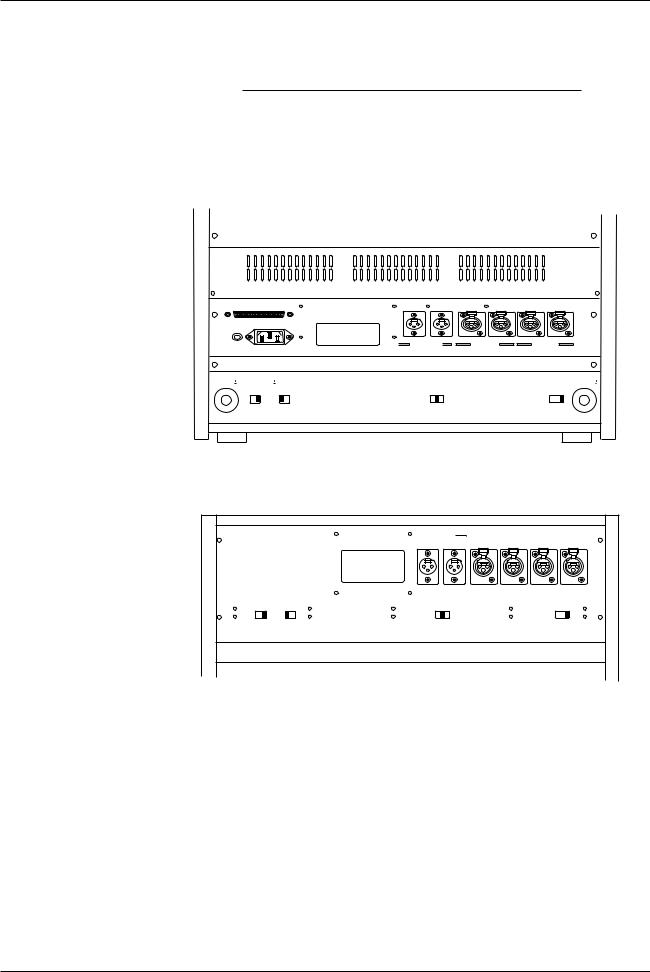
The connections to the Input/Output connectors are as shown in Figure 2-1.
BIII
PARALLEL I/O
CH 2 |
CH 1 |
|
|
|
|
|
|
|
CH 2 |
CH 1 |
|||||||
LINE |
OUTPUT |
|
|
|
LINE INPUT |
|
|
|
|
|
|
|
MIC |
INPUT |
|
|
|
GROUND POWER
OUTPUT INPUT
MKIV-2
INPUT
LINE |
OUTPUT |
LINE INPUT |
MIC |
INPUT |
CH 2 |
CH 1 |
|
CH 2 |
CH 1 |
OUTPUT LEVEL |
EQUALIZATION |
REF FLUX |
MIC ATTENUATOR |
LOW HIGH |
IEC NAB |
LOW MID HIGH |
OdB-2OdB OFF |
OUTPUT
Figure 2-1
Input/Output Connectors
May 1992 |
2 - 3 |

Section 2 Installation |
MX-5050 Operation and Maintenance Manual |
2.2.2 Balanced/Unbalanced Connection
The Input/Output connectors are balanced as shown in Figure 2-2. The pin assignment of the connectors is as follows:
Pin 1: Shield (GND)
Pin 2: Cold
Pin 3: Hot.
When connecting an unbalanced machine to the MX-5050, change the pin assignment as shown in Figure 2-2.
|
|
2 |
|
|
1 |
|
|
|
|
|
|
|
|
|
1 |
|
2 |
2 |
1 GND |
1 |
GND |
|
COLD |
COLD |
|
(SHIELD) |
|
2 |
|
|
|
|
|||
|
|
|
|
|
|
|
|
3 |
|
3 |
3 |
|
3 |
|
|
HOT |
|
|
|
|
|
HOT
Balanced Input |
Balanced Output |
|
2 |
|
|
|
1 |
|
|
|
|
GND |
|
2 |
1 GND |
1 |
1 |
2 |
2 |
|
|||||
|
3 |
|
|
|
3 |
|
3 |
|
|
3 |
|
|
HOT |
|
|
HOT |
|
Unbalanced Input |
Unbalanced Output |
Figure 2-2 |
Optional Input (ZA-53T)/Output (ZA-53S) Transformers are available from |
Balanced/Unbalanced Connectors |
OTARI. For details contact OTARI or your nearest OTARI dealer. |
2 - 4 |
May 1992 |
MX-5050 Operation and Maintenance Manual |
Section 2 Installation |
2.3 Switch Position Adjustment
Table 2-2
Settings on Rear Panel
If necessary, change the following switch settings on the rear panel before operating the machine.
Function |
Switch |
Setting |
MIC. Attenuator |
SW501 |
0dB/-20dB/OFF |
REF FLUX |
SW502 |
H/M/L (320/250/185nWb/m) |
EQ Setting |
SW503 |
NAB/IEC |
Output Level Setting |
SW504 |
H: +4dBu, L: -16dBu |
|
|
|
BIII
PARALLEL I/O
CH 2 |
CH 1 |
CH 2 |
CH 1 |
CH 2 |
CH 1 |
LINE |
OUTPUT |
LINE |
INPUT |
MIC |
INPUT |
GROUND POWER
 OUTPUT LEVEL
 EQUALIZATION
  REF FLUX
  MIC ATTENUATOR
LOW HIGH IEC NAB |
LOW MID HIGH |
OdB -2OdB OFF |
MKIV-2
 LINE OUTPUT
 LINE INPUT
 MIC INPUT
CH 2 |
CH 1 |
CH 2 |
CH 1 |
CH 2 |
CH 1 |
OUTPUT LEVEL |
EQUALIZATION |
REF FLUX |
MIC ATTENUATOR |
LOW HIGH |
IEC NAB |
LOW MID HIGH |
OdB-2OdB OFF |
Figure 2-3
Switch Settings on Rear Panel
May 1992 |
2 - 5 |
Section 2 Installation |
MX-5050 Operation and Maintenance Manual |
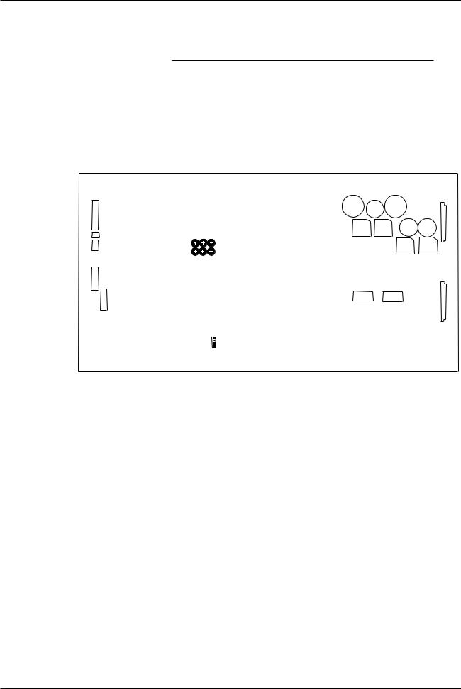
Table 2-3
DIP SW Settings on the Control PCB
CN 27
CN26
CN25
CN24
CN23
DIP SW settings on the CONTROL PCB
Note: When any of the following DIP SW settings are changed, the machine must be turned off and on for the settings to take effect.
SW1 |
SW2 |
|
|
|
SW1-1 Speed Version |
SW2-1 SEARCH 3 key Selection |
|
|
|
SW1-2 Punch-In |
SW2-2 SEARCH 3 key Selection |
|
|
|
SW1-3 Punch-Out |
SW2-3 Stop Mute Selection |
|
|
|
SW1-4 Capstan PLL Reference |
SW2-4 Fast Wind Mute Selection |
|||
SW1-5 Capstan PLL Reference |
SW2-5 Play Start Mute |
|
|
|
SW1-6 Punch-In Type Select |
SW2-6 Machine Type |
|
|
|
SW1-7 REC LED Flashing Select |
SW2-7 Machine Type |
|
|
|
SW1-8 External Control Select |
SW2-8 Not used |
|
|
|
|
|
|
|
|
|
C21 |
C18 |
|
|
|
C19 |
|
|
|
|
|
C10 |
C9 |
|
|
|
|
|
CN3 |
VR6 VR5 VR4 |
|
|
|
|
|
D46 |
D45 |
|
|
VR3 VR2 VR1 |
|
D44 |
D43 |
|
|
|
|||
CN7
SW2 SW1
SW3
Figure 2-4
Controls on the CONTROL PCB Assembly
Refer to Fig 2-4 for the location of these DIP switches on the CONTROL PCB
Assembly.
SW1-1 Speed Version Selection (BIII-2)
ON |
3.75/7.5 ips: Low Speed Version (Option) |
OFF |
15/7.5 ips: High Speed Version |
The BIII-2 is set to High Speed at the factory. After receiving the BIII-2, it can be changed to Low Speed with this switch. Refer to §2.8 for details. The
MKIV-2 cannot be changed to Low Speed.
SW1-2 Punch-In (Refer to § 3.2, [18] REC button)
ON |
Press REC and PLAY buttons in PLAY mode to begin Punch-In |
OFF |
Press REC button in PLAY mode to begin Punch-In |
SW1-3 Punch-Out (Refer to § 3.2, [19] PLAY button)
ON |
Press PLAY button to end the Punch-In Record |
OFF |
Press STOP and REC button to end the Punch-In Record |
2 - 6 |
May 1992 |

MX-5050 Operation and Maintenance Manual |
Section 2 Installation |
Table 2-4
Capstan PLL Reference Setting
Table 2-5
SEARCH 3 Key Function
SW1-4, 1-5 Capstan PLL Reference Setting
When the machine is in FIX mode, the capstan speed is adjusted with these switches (refer to § 6.7).
SW1-4 |
SW1-5 |
OFF SET (%) |
ON |
ON |
+ 0.2% |
OFF |
ON |
– 0.2% |
ON |
OFF |
– 0.4% |
OFF |
OFF |
Not used |
SW 1-6 Adding Punch In Type Selection
ON Edge Type
With this setting, the Punch In command signal is as shown above. Additional Punch-Ins are made by pressing the PLAY and REC buttons (or just the REC button) while in Ready mode.
OFF Level Type
With this setting, the Punch In command signal is as shown above. Additional Punch-Ins are made by changing READY/SAFE switches from the SAFE position to the READY position.
SW1-7 Flashing REC button selection
This switch selects whether the lamp on the REC button flashes when the READY/SAFE switch is set to READY.
ON |
Illuminates (does not flash) |
OFF |
Flashes |
SW1-8 \
SW2-1, 2-2
These switches select the function of the SEARCH 3 key.
SW2-1 |
2-2 |
Function |
ON |
ON |
Proximity Sensor ON/OFF key * |
OFF |
ON |
Not used |
ON |
OFF |
Search Start (§ 4.5.6) |
OFF |
OFF |
Search Cue (§ 4.5.3) Default Setting |
|
|
|
*When using the optional proximity sensor, pressing the SEARCH 3 key enables/disables the Proximity Sensor Function.
May 1992 |
2 - 7 |

Section 2 Installation |
MX-5050 Operation and Maintenance Manual |
Table 2-6
Machine Type
SW2-3
This switch selects whether the audio signal is muted during the time from when the STOP button is pressed until the machine actually stops.
ON: Not Mute
OFF: Mute
SW2-4
This switch selects whether the audio signal is muted during Fast Wind modes other than Fast Wind Cue mode.
ON: Not Mute
OFF: Mute
SW2-5
This switch selects whether the audio is muted during the time from when the PLAY button is pressed until the tape enters Play mode.
ON: Not Mute
OFF: Mute
SW2-6, 2-7
These switch settings determine the machine type. These switches are set at the factory and should not be changed.
SW2-6 |
SW2-7 |
Type |
Tape |
Rehearsal |
Size |
ON |
ON |
8CH |
1/2" |
O |
O |
OFF |
ON |
4CH |
1/2" |
O |
O |
ON |
OFF |
4CH |
1/4" |
O |
O |
|
|
|
|
|
|
SW2-8
Not Used
2 - 8 |
May 1992 |
MX-5050 Operation and Maintenance Manual |
Section 2 Installation |
2.4PCB Assembly Location
2.4.1MX-5050 BIII
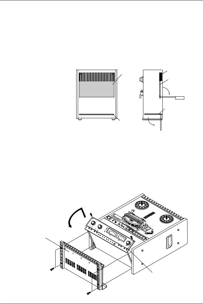
The PCB Assemblies are located as shown in Figure 2-5. The CONTROL PCB Assembly is accessed by removing the rear panel. (Refer to Figure 2-9). The CONTROL PCB can be rotated to adjust parts on the COMP side. To access the REC/ REP AMP PCB Assembly, the AMP section of the MX-5050BIII must be turned face up. The rotation of the AMP section is performed as follows.
BIII
SCREW
CONTROL PCB
CONTROL PCB
REC/REP PCB
REC/REP PCB
Figure 2-5
PCB Assembly Location (BIII)
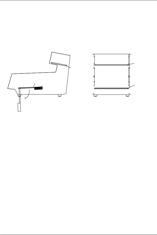
AMP Section Rotation
1.Turn off the machine. Place the machine so that the transport faces upward. Refer to Figure 2-6.
2.Remove the four screws holding the Bottom Cover. Remove the Bottom Cover from the machine.
3.Remove the four screws holding the AMP section. While lifting the AMP section slightly, rotate it to a horizontal position.
Bottom Cover
AMP Section
Figure 2-6
AMP Section Rotation
May 1992 |
2 - 9 |
Section 2 Installation |
MX-5050 Operation and Maintenance Manual |
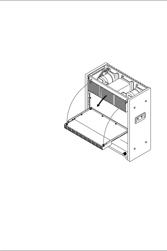
CONTROL PCB Assembly Rotation
1.Turn off the machine. Place the machine in the upright position. See Figure 2-7.
2.Remove the Foot and Deck Stand from the Rear Cover.
3.Remove the Rear Cover by removing the screws holding it in place.
4.Loosen the two screws holding the Heat sink. Rotate the CONTROL PCB Assembly on its side.
5.The Side Boards may need to be removed to access some controls on the CONTROL PCB Assembly.
Figure 2- 7
CONTROL PCB Assembly Rotation
2 - 10 |
May 1992 |
MX-5050 Operation and Maintenance Manual |
Section 2 Installation |
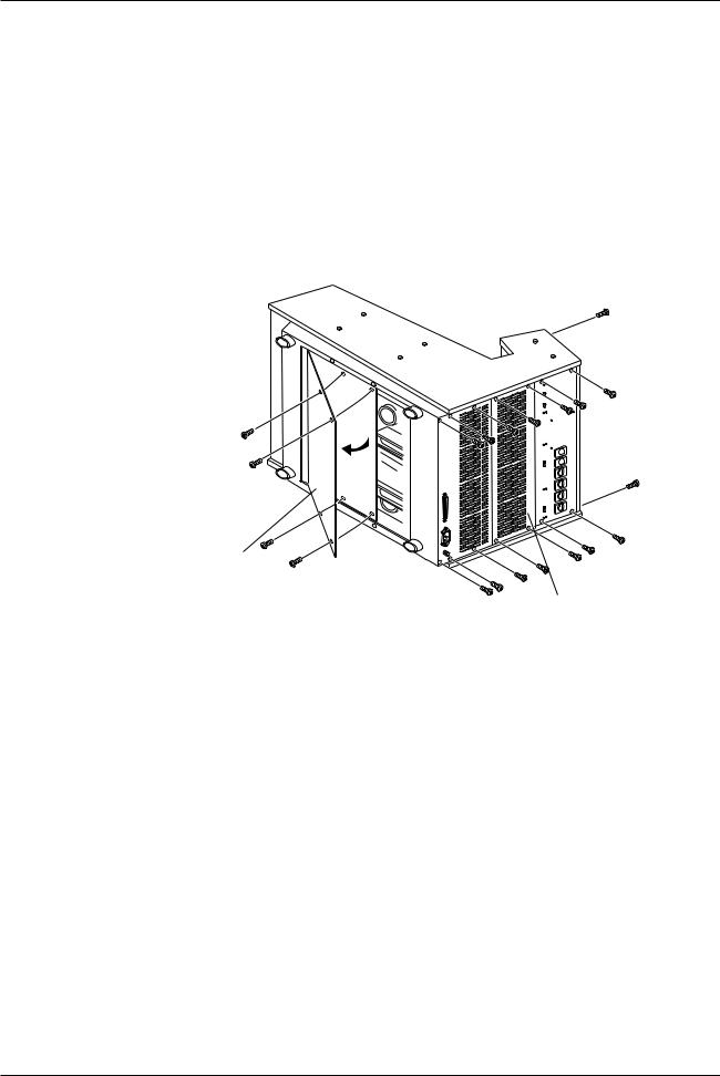
2.4.2 MX-5050 MKIV2
The AMP section of the MKIV-2 is adjusted after removing the Top Panel.
Accessing the AMP Section
1.Turn off the machine. Remove the Top Panel (for MKIV-2).
2.Adjust the PCB Assemblies (REC/REP AMP PCB Assembly) located inside the AMP section.
REC/REP PCB
REC/REP PCB
CONTROL PCB
SCREW |
CONTROL PCB |
Figure 2-8
PCB Assembly Location
May 1992 |
2 - 11 |
Section 2 Installation |
MX-5050 Operation and Maintenance Manual |
CONTROL PCB Assembly Rotation
Follow the steps below when adjusting the CONTROL PCB Assembly and internal parts of the MKIV-2.
1.Turn off the machine. Lay the machine on its side.
2.Remove the Bottom Panel by removing the screws holding it.
3.Loosen the two screws holding the Heat Sink on the Control PCB Assembly. Rotate the CONTROL PCB Assembly.
4.Depending on the parts to be adjusted, the side panel may also need to be removed.
CONTROL PCB
REAR PANEL
Figure 2-9
CONTROL PCB Assembly Rotation (MKIV-2)
2 - 12 |
May 1992 |
 Loading...