

Page 1
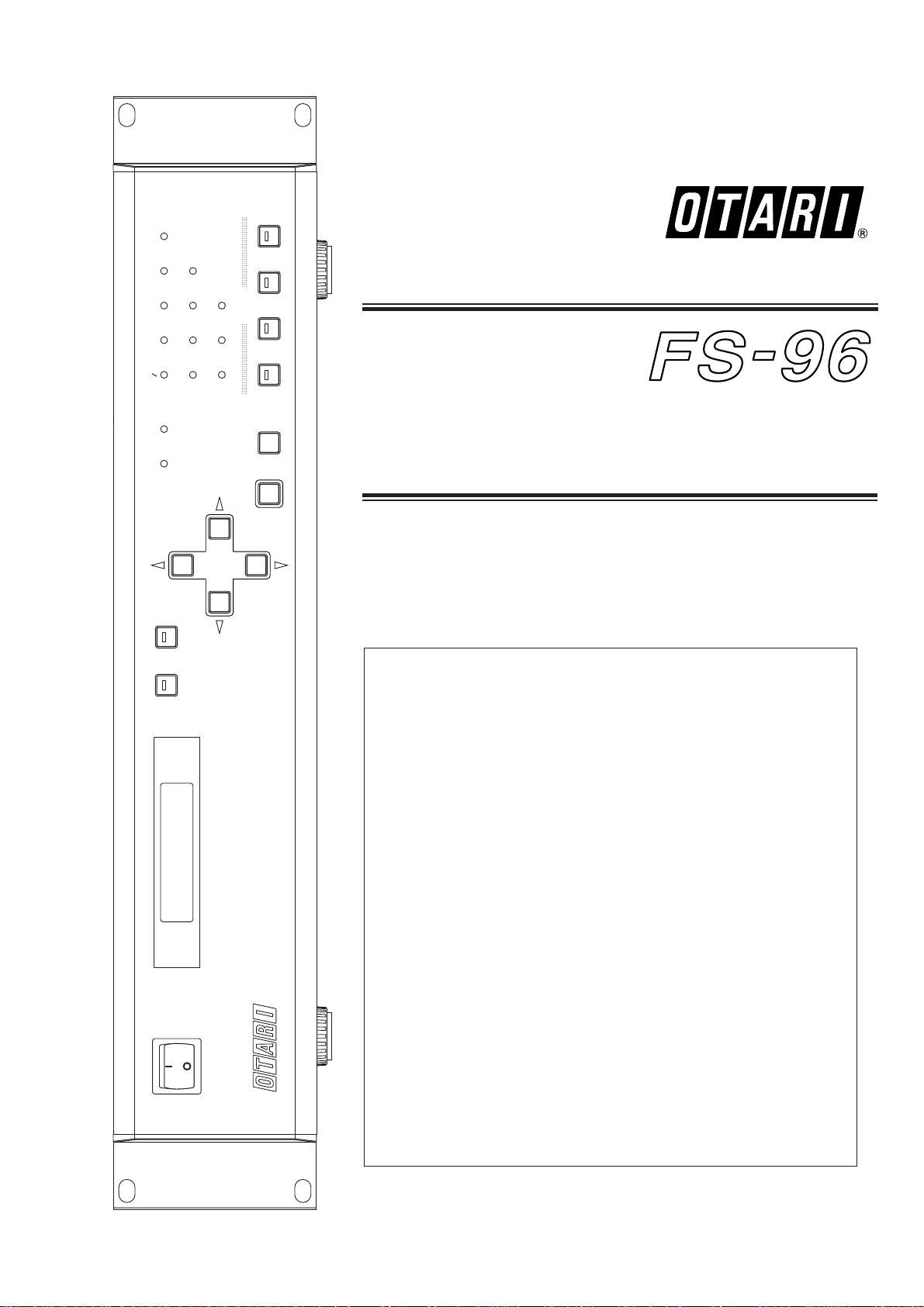
Part No. OS1-132
February 2001
Ed.2 (TM)
Operation Manual
SETUP ROUTING
SRC AES EBU
96kHz 48kHz 44.1kHz 32kHz
INT EXT INPUT
ADAT SDIF
-
2 TDIF
-
1 OPTION
PRESET
ENTER CANCEL
1
:
1
1234
POWER
FORMAT & SAMPLE RATE CONVERTER
FS--96
Format & Sample Rate
Converter
Getting Started
Welcome to Otari FS-96 ....................4
Main Features ..............................4
Unpacking and Inspection ...................5
Conventions within this Manual ..............5
About Digital Audio Formats .................5
Controls and Indicators
Front Panel .................................6
Rear Panel .................................7
Installation and Connection
Installation ..................................8
Power Supply and Grounding ...............8
Connecting Word Clock Signals .............8
Connecting
ADAT Optical Format Signals
.....9
Connecting AES/EBU Format Signals ........9
Connecting SDIF-2 Format Signals ..........9
Connecting TDIF-1 Format Signals ..........9
Basic Operation
Powering Up ..............................10
Basic Setup Instructions ...................10
Operations with LCD ......................11
Modes of Operation .......................11
Resetting All Settings ......................12
Using Key Lock Function ...................12
Considering Signal Delay ...................12
Mis-synchronization due to
Additional Signal Connection .........12
Operating Memories
Using Preset Memories ....................13
Recalling Preset Memories .................13
Duplicating Preset Memories ...............14
Clearing Preset Memories ..................14
Using PRESET Keys .......................15
Setup Mode
Operations in Setup Mode .................16
Selecting Input Format .....................17
Selecting Reference Clock .................18
Configuring Sample Rate Converter ........19
Changing Bit Resolution ...................20
Activating Dither Function ..................20
Editing Status Data ........................21
Adjusting Sync Timing .....................22
Adjusting LCD Contrast ....................23
Routing Mode
Configuring Signal Routing .................24
BI-DIRECTION MODE
Using Bi-Direction Mode ...................25
SPECIFICATIONS
FS-96 Specifications .......................26
TABLE OF CONTENTS
Page 2
Otari FS-96 Format & Sample Rate Converter Operation Manual
Part No. : OS1-132
Copyright © 2000, 2001 by Otari, Inc.
Printed in Japan
This manual may not be reproduced by any means without written permission.
FS-96 and Otari are trademarks of Otari, Inc.
All other trademarks are property of their respective owners.
To prevent fire or shock hazard:
• Do not remove panels (unless instructed to do so).
• There are no user-serviceable parts inside.
Refer servicing to qualified service personnel.
• Do not expose this unit to rain or moisture.
NOTE
This equipment has been tested and found to comply with the limits for a
Class B digital device, pursuant to Part 15 of the FCC Rules. These limits
are designed to provide reasonable protection against harmful interference
in a residential installation. This equipment generates, uses, and can radiate
radio frequency energy and, if not installed and used in accordance with the
instructions, may cause harmful interference to radio communications.
However, there is no guarantee that interference will not occur in a
particular installation. If this equipment does cause harmful interference to
radio or television reception, which can be determined by turning the
equipment off and on, the user is encouraged to try to correct the
interference by one or more of the following measures:
• Reorient or relocate the receiving antenna.
• Increase the separation between the equipment and receiver.
• Connect the equipment into an outlet on a circuit different from that to
which the receiver is connected.
• Consult the dealer or an experienced radio/TV technician for help.
CAUTION
RISK OF ELECTRIC SHOCK
DO NOT OPEN
PLEASE READ THROUGH THE SAFETY INSTRUCTIONS ON THE NEXT PAGE.
The lightning flash with arrowhead symbol, within an equilateral
triangle, is intended to alert the user to the presence of uninsulated
“dangerous voltage” within the product’s enclosure that may be of
sufficient magnitude to constitute a risk of electric shock to persons.
The exclamation point within an equilateral triangle is intended to alert
the user to the presence of important operating and maintenance
(servicing) instructions in the the literature accompanying the
appliance.
Page 3
1. Read Instructions: All safety and operating instructions should
be read before the device is operated.
2. Retain Instructions: The safety and operating instructions
should be retained for future reference.
3. Heed Warnings: All warnings on the device and in the
operating instructions should be complied with.
4. Follow Instructions: All operating and use instructions should
be followed.
5. Water and Moisture: The device should not be used near
water — for example, near a bathtub, wash bowl, sink, laundry
tub, in a wet basement, near a swimming pool, etc.
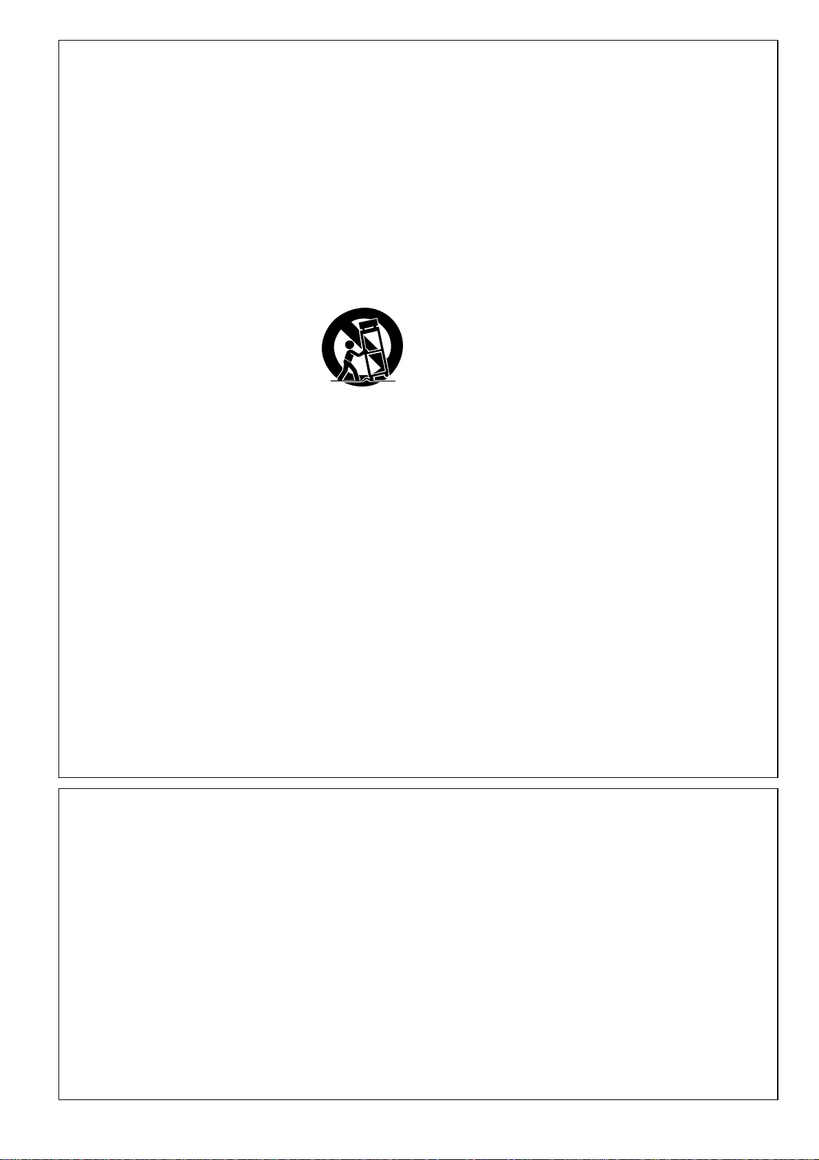
6. Carts and Stands: The device should be
used only with a cart or stand that is
recommended by the manufacturer.
A product and cart combination should be
moved with care. Quick stops, excessive
force, and uneven surfaces may cause the
product and cart combination to overturn.
7. Ventilation: The device should be situated so that its location or
position does not interfere with its proper ventilation. For
example, the device should not be situated on a bed, sofa, rug,
or similar surface that may block the ventilation openings; or,
placed in a built-in installation, such as a bookcase or cabinet
that may impede the flow of air through the ventilation openings.
8. Heat: The device should be situated away from heat sources
such as a radiator, heat register, stove or other appliances
(including amplifiers) that produce heat.
9. Power Sources: The device should be connected to a power
supply only of the type described in the operating instructions or
as marked on the device.
10. Power Cord Handling: Handle the power cord by the plug. Do
not pull out the plug by tugging the cord and never touch the
power cord when your hands are wet as this could cause a
short circuit or electric shock. Do not place the unit, a piece of
furniture, etc., on the power cord, or pinch the cord. Never make
a knot in the cord or tie it with other cords. The power cords
should be routed such a way that they are not likely to be
stepped on. A damaged power cord can cause a fire or give you
an electrical shock. Check the power cord regularly. When you
find it damaged, ask your nearest dealer for a replacement.
11. Power Cord Protection: Power supply cords should be routed
so that they are not likely to be walked on or pinched by items
placed upon or against them, paying particular attention to cords
at plugs, convenience receptacles, and the point where they exit
from the device.
12. Grounding or Polarization:
• If this product is equipped with a polarized alternating current
line plug (a plug having one blade wider than the other). This
plug will fit into the power outlet only one way. This is a safety
feature. If you are unable to insert the plug fully into the outlet,
try reversing the plug. If the plug should still fail to fit, contact
your electrician to replace your obsolete outlet. Do not defeat
the safety purpose of the polarized plug.
• If this product is equipped with a three-wire grounding type
plug, a plug having a third (grounding) pin, it will only fit into a
grounding type power outlet. This is a safety feature. If you are
unable to insert the plug into the outlet, contact your electrician
to replace your obsolete outlet. Do not defeat the safety
purpose of the grounding type plug.
13. Cleaning: The device should be cleaned only as recommended
by the manufacturer.
14. Non-Use Periods: The power cord of the device should be
unplugged from the outlet when left unused for a long period of
time.
15. Object and Liquid Entry: Care should be taken that objects do
not enter and that liquids are not spilled into the enclosure
through any openings.
16. Damage Requiring Service: The device should be serviced by
qualified service personnel when:
a. The power supply cord or the plug has been damaged; or
b. Objects have entered, or liquid has been spilled into the
appliance; or
c. The appliance has been exposed to rain; or
d. The appliance does not appear to operate normally or
exhibits a marked change in performance; or
e. The appliance has been dropped, or the enclosure
damaged.
17. Servicing: The user should not attempt to service the device
beyond what is described in the operating instructions. All other
service should be referred to qualified personnel.
Another part of Otari’s continuing technical support program for our
products is the continuous revision of manuals as the equipment is
improved or modified. In order for you to receive the information and
support which is applicable to your equipment, and for the technical
support program to function properly, please include the following
information, most of which can be obtained from the Serial number
label on the machine, in all correspondence with Otari:
• Model Number:
• Serial Number:
• Date of Purchase:
• Name and address of the dealer where the machine was
purchased and the power requirements (voltage and frequency) of
the machine.
SAFETY INSTRUCTIONS
All Otari products are manufactured under strict quality control. Each
unit is carefully inspected and tested prior to shipment. If, however,
some adjustment or technical support becomes necessary,
replacement parts are required, or technical questions arise, please
contact your Otari dealer or contact Otari at:
Otari, Inc. Otari Corporation
4-33-3 Kokuryo-cho 8236 Remmet Avenue
Chofu-shi, Tokyo 182 Japan Canoga Park, California 91304 U.S.A.
Phone : +81
/
42481-8626 Phone : +1/818-598-1200
Fax : +81
/
42481-8633 Fax : +1/818-594-7208
URL : www.otari.co.jp URL : www.otari.com
Otari Europe GmbH Otari Singapore Pte., Ltd.
Rudolf-Diesel-Strasse 12 701 Sims Drive #02-02 LHK Building
D-40670 Meerbusch, Germany Singapore 387383
Phone : +49
/
2159-50861 Phone : +65/846-1553
Fax : +49
/
2159-1778 Fax : +65/846-7875
COMMUNICATION WITH OTARI
FOR SERVICE INFORMATION AND PARTS
February 2001 3
Page 4
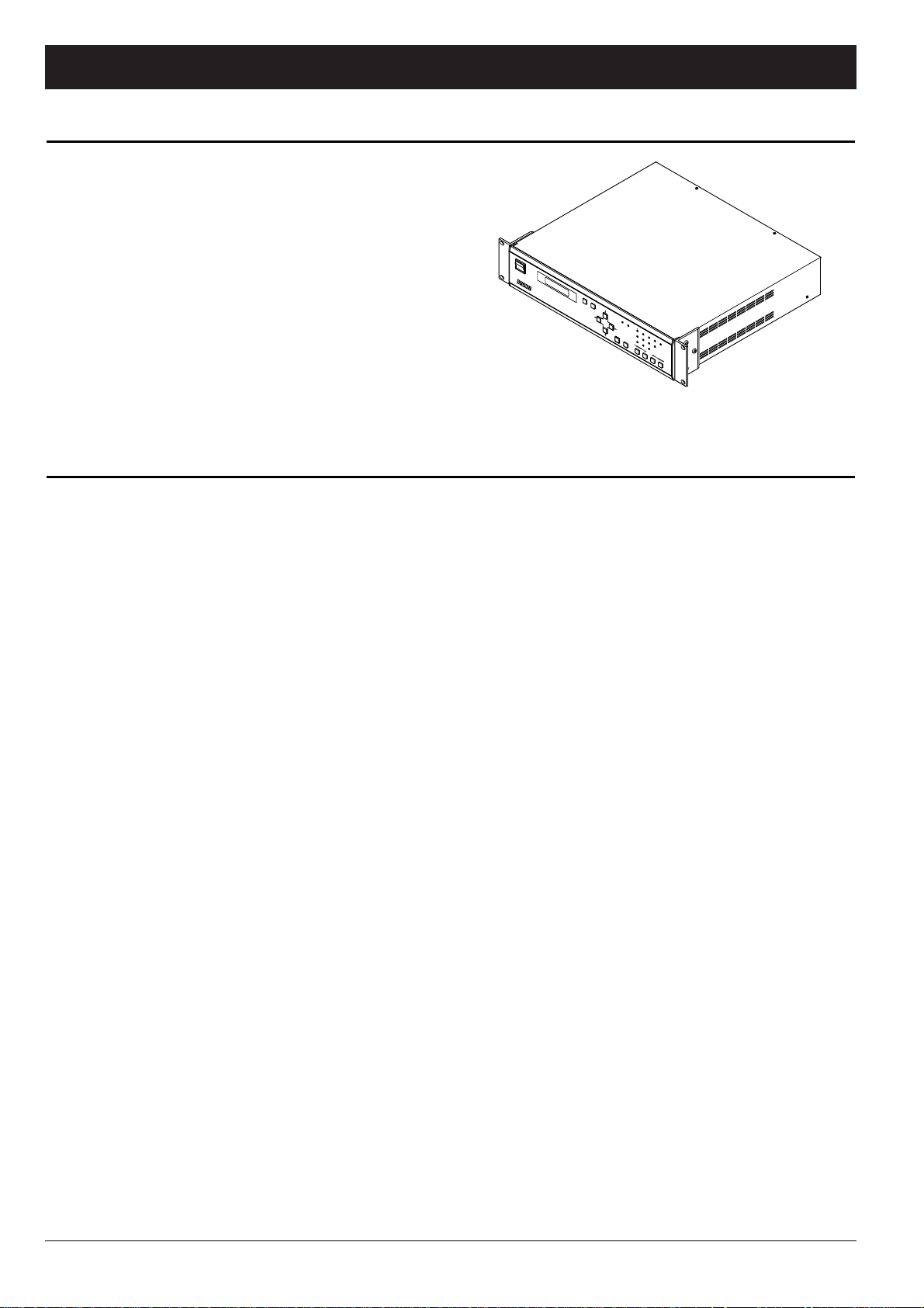
Congratulations on your purchase of the Otari FS-96!
The Otari FS-96 is a device for converting signal formats and
sample rates of digital audio signals. A total of five professional
digital audio formats (ADAT, AES/EBU, SDIF-2, TDIF-1, OPTION)
are supported and 24 channels of digital audio signals can be
converted simultaneously to all of the signal formats available on
the FS-96, at the desired sample rate.
In addition to the format and sample rate conversion capabilities,
the FS-96 can be used as a digital signal router and the
connections between the input and output channels can be
changed internally without changing any physical connections.
SETUP ROUTING
SRC AES EBU
96kHz 48kHz 44.1kHz32kHz
INT EXT INPUT
ADAT SDIF
2
TDIF
1
OPTION
PRESET
ENTER CANCEL
1
:
1
1234
POW
ER
FORMAT & SAMPLE RATE CONVERTER
FS--96
■ Five Digital Audio Formats: The FS-96 supports five digital
audio formats (ADAT, AES/EBU, SDIF-2, TDIF-1, OPTION). The
digital audio signals input in any of these formats can be output
in all of the formats available on the FS-96.
■ 24-channel Capacity with Signal Routing Function: The
FS-96 can handle 24 channels of audio inputs at the same time.
By using the signal routing function, the connections between
the input and output channels can be changed internally without
changing any physical connections.
■ 96 kHz Sample Rate & 24-bit Quantization: The FS-96
supports sample rates of 32 kHz to 96 kHz and bit resolution of
16 to 24 bit. By using the internal sample rate converters, the
sample rate and bit resolution of the input audio can be changed
as desired.
■ Same Format Sample Rate Conversion: Whenever audio is
input in a given format, the output for that same format is also
available, and it can be sample rate converted to the same
output format if needed.
■ Accurate Clock Generation Circuit: The FS-96 is equipped
with an accurate clock generation circuit for achieving signal
accuracy at professional level . Even unstable digital inputs can
be regenerated as accurate outputs.
■ Preset Memories for Operation and Routing Settings:
A maximum of 10 preset memories can be used for storing each
of operation and routing settings.Furthermore, combinations of
operation and routing memories can be stored into four PRESET
keys and they can be recalled by merely pressing a PRESET key.
■ Various Signal Synchronization: The output audio can be
synchronized to any of three signals — FS-96’s internal clock
signal, external Word Clock signal, and the input audio signal.
■ Linking Multiple Units with Sample Accuracy: Multiple FS-
96 units can be synchronized with phase-level sample accuracy
by linking the units using Word Clock signals.
■ Bi-directional Conversion with TDIF and AES/EBU:
Simultaneous bi-directional signal format conversions are
possible between the TDIF-1 and AES/EBU interfaces. This
mode is provided especially for digital recorders having the TDIF1 interfaces.
■ Status Data Editing Function: It is possible to edit the
status data contained in each of the digital audio formats.
■ Expansion with Option Slots: An option slot is provided on
the rear panel to accept a new digital audio format by inserting
an expansion module.
■ Comprehensive Operations with LCD: All system
configurations are done in menu-driven screens via the LCD.
■ 19" Standard Rack: Each FS-96 includes a set of adapters
for installing into a standard 19-inch rack. The FS-96 occupies
only a 2U rack space.
■ Universal Power Supply Included: The FS-96 is equipped
with a universal power supply circuit which supports AC voltages
and frequencies used all over the world.
4 February 2001
Getting Started
Welcome to Otari FS-96
Main Features
Page 5
■ Unpacking: Each FS-96 is carefully packed and shipped to
avoid damage during transportation. We recommend that you
open the carton carefully and retain the packing materials at
least until proper operation of the machine has been established.
■ Visual Inspection: After unpacking, inspect the FS-96
visually. If there is any evidence of damage due to rough
handling during shipping, you must notify the transportation
carrier and submit a claim. Do not connect or use the FS-96 if
damage is found.
■ Confirmation of Standard Accessories: Check that the
carton contains the following standard accessories:
PART NAME PART NO. Q’TY DESCRIPTION
FOOT CY4176-- 4 PRE-INSTALLED
RACK MOUNT ADAPTER KZ2Z222- 2 PRE-INSTALLED
FUSE (3.15 A, 250 V) FH9-020 1
POWER SUPPLY CORD PZ9D003- 1
OPERATION MANUAL OS1-132- 1 THIS BOOKLET *
■ Machine Names: When describing a FS-96, we use the
terms “FS-96” or simply “unit”.
■ Upper Case: We use all upper case type to describe a button
or control when that item is similarly labeled on the machine
(e.g., POWER switch). Machine status or operating modes are
described with an upper case first letter.
■ AES/EBU (AES3) Format: This format was standardized by
the AES
[Audio Engineering Society] and EBU [European Broadcasting Union]
jointly. The signals consist of 2-channel stereo pairs and are
connected with cables having 110 Ω impedance. The FS-96
uses three 25-pin D-sub connectors for both inputs and outputs
and each of the connectors can handle 8 channels (4 stereo
pairs) of digital audio.
■ ADAT Optical
[Alesis multi-channel optical digital interface]
Format: This format was developed by Alesis especially for
ADAT recorders and is referred to as “Alesis Lightpipe”.
A dedicated optic fiber cable is used for connecting 8 channels
of digital audio. The FS-96 provides three systems of ADAT
interfaces for handling a total of 24 channels.
■ SDIF
[Sony Digital InterFace] Format: This format was developed
by Sony for handling 24 channels of digital audio. A 50-pin D-sub
connector is used for connecting the 24 channels simultaneously.
A Word Clock signal is needed as a synchronization signal. This
format is also referred to as “DASH” format.
■ TDIF
[Tascam Digital InterFace] Format: This format was
developed by Tascam and uses a 25-pin D-sub connector for
both inputs and outputs 8 channels of digital audio signals. The
signals consist of 4 systems of 2-channel multiplexed pairs. The
FS-96 uses three 25-pin D-sub connectors for handling a total of
24 channels.
The FS-96 supports signals of up to 24-bit and
96 kHz in all of the above four formats.
However, the 96 kHz signals are not supported
officially in the formats other than AES/EBU.
Thus, please be aware that Otari does not
guarantee the performance of the 96 kHz
signals in these formats.
■ MADI
[Multi-channel Audio Digital Interface] Format (Optional):
This format was standardized by AES
[Audio Engineering Society] for
transmitting multi-channel digital audio signals. This format is
mainly used as an audio interface for digital mixing consoles and
a maximum of 56 channels of audio can be transmitted with one
coaxial cable. The FS-96 can handle a maximum of 24 channels
of MADI signals, by installing the optional MADI expansion
module [ZA-9CF-S] into the option slot.
The current MADI format does not support
signals having a sample rate higher than 48
kHz.
February 2001 5
Getting Started
Unpacking and Inspection
Conventions within this Manual
About Digital Audio Formats
The FS-96 can handle the following five digital audio formats:
Page 6
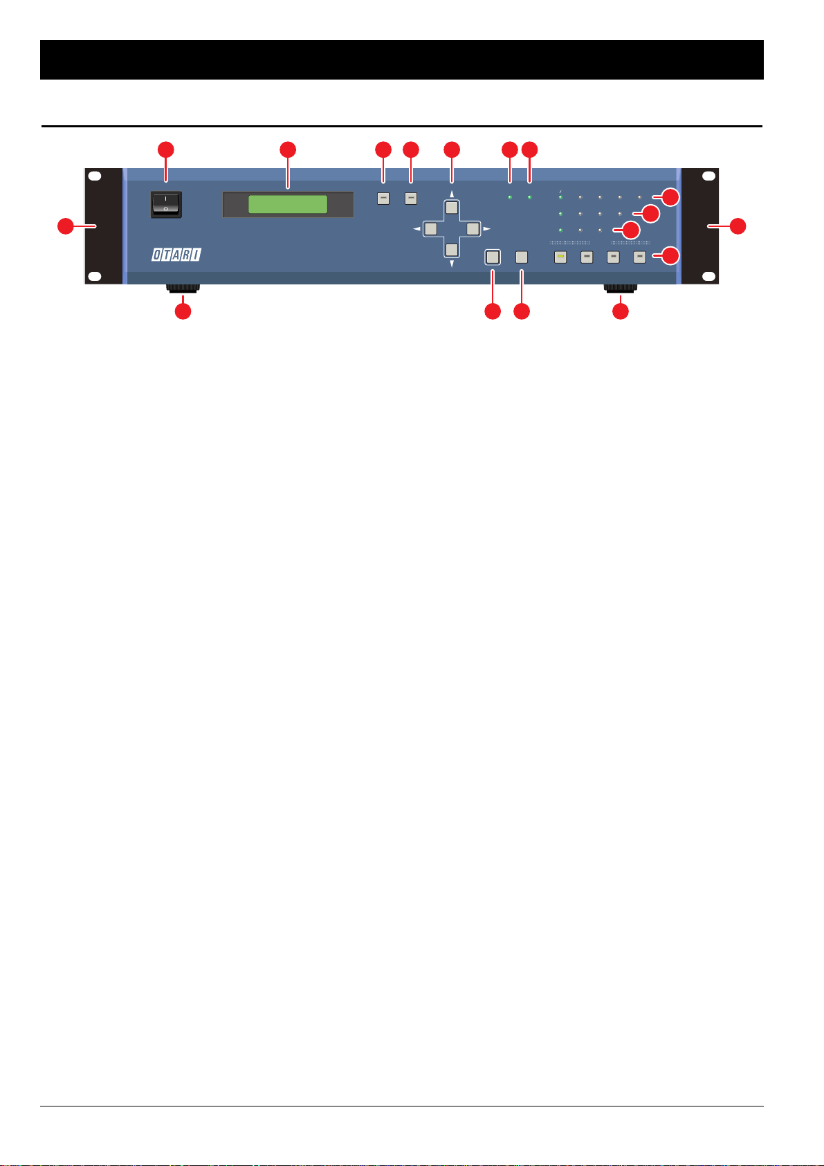
Front Panel
[1] POWER switch
Used to power up and shut down the unit. Press the “I” side to
turn the unit on and press the “O” side to turn it off.
[2] LCD (Liquid Crystal Display)
Displays various system settings and signal routing
configurations with a 16-character x 2-line display. A back-light
mechanism is provided.
[3] SETUP key
Used to put the FS-96 into Setup mode for making operation
settings. When the SETUP key is pressed, the key’s LED
illuminates and the FS-96 enters Setup mode. In this mode,
various system settings excluding routing configuration can be
made via the LCD. Up to 10 sets of parameter values can be
stored into the setting memories.
[4] ROUTING key
Used to put the FS-96 into Routing mode for making signal
routing configurations. When the ROUTING key is pressed, the
key’s LED illuminates and the FS-96 enters Routing mode. In this
mode, internal connections of the input and output channels can
be changed via the LCD. Up to 10 signal routing settings can be
stored into the routing memories.
[5] Arrow keys
Used to change the LCD screen, or to move the cursor on the
screen. When a parameter is selected on the LCD, these keys
are used to change the parameter value.
[6] ENTER key
Used to select a parameter value on the LCD screen, or to store
a parameter value.
[7] CANCEL key
Used to stop the entry of parameter values, or to return the
screen to the previous one.
[8] SRC [Sample Rate Converter] indicator
Illuminates when the sample rate converter is turned on.
If the sample rate converter does not operate properly, this
indicator flashes.
[9] 1 : 1 indicator
Illuminates when the signal routing is OFF. When this indicator is
lit, the input channels are connected to the same output
channels.
[10] Source indicators
(AES/EBU, ADAT, SDIF-2, TDIF-1, OPTION)
Display the selection of the input format. If no signal is present or
synchronization to the input signal cannot be obtained, the
indicator for the selected format will flash.
[11] Sample Rate indicators
(96 kHz, 48 kHz, 44.1 kHz, 32 kHz)
Display the sample rate of the output signals. Note that each
indicator will illuminate when the sample rate is within a range of
±1 % of the indicated frequency. Both the 32 kHz and 44.1 kHz
indicators are lit for the 64 kHz sample rate. Also, both the 44.1
kHz and 48 kHz indicators are lit for the 88.2 kHz sample rate.
[12] Reference Clock indicators (INT, EXT, INPUT)
Display the selection of the reference clock for the output signals
— INT = FS-96’s internal clock signal, EXT = external Word
Clock signal, INPUT = input audio signal. When the EXT or
INPUT is selected, the indicator for the selected signal will flash,
if no signal is present or if the synchronization cannot be
achieved with the input signal.
[13] PRESET keys 1 – 4
Used to store combinations of setting and routing memories.
When a PRESET key is pressed, the stored combination will be
recalled and the system configurations will be changed
momentarily. The key’s indicator illuminates when the stored
combination is being used.
[14] Rack mount adapters
Used to install the FS-96 into a standard 19-inch rack. The
adapters can be removed if they are not necessary.
[15] Feet
If the FS-96 is to be installed in a standard 19-inch rack, remove
the feet.
6 February 2001
Controls and Indicators
SETUP ROUTING
SRC AES EBU
96kHz 48kHz 44.1kHz 32kHz
INT EXT INPUT
ADAT SDIF-2 TDIF-1 OPTION
PRESET
ENTER CANCEL
1:1
1234
POWER
FORMAFORMAT & SAMPLE RAT & SAMPLE RATE CONVERTERTE CONVERTER
FS--96
SETTING MEM.: 0
ROUTING MEM.: 0
1 2 3 84 95
14 14
15 76 15
10
13
11
12
Page 7
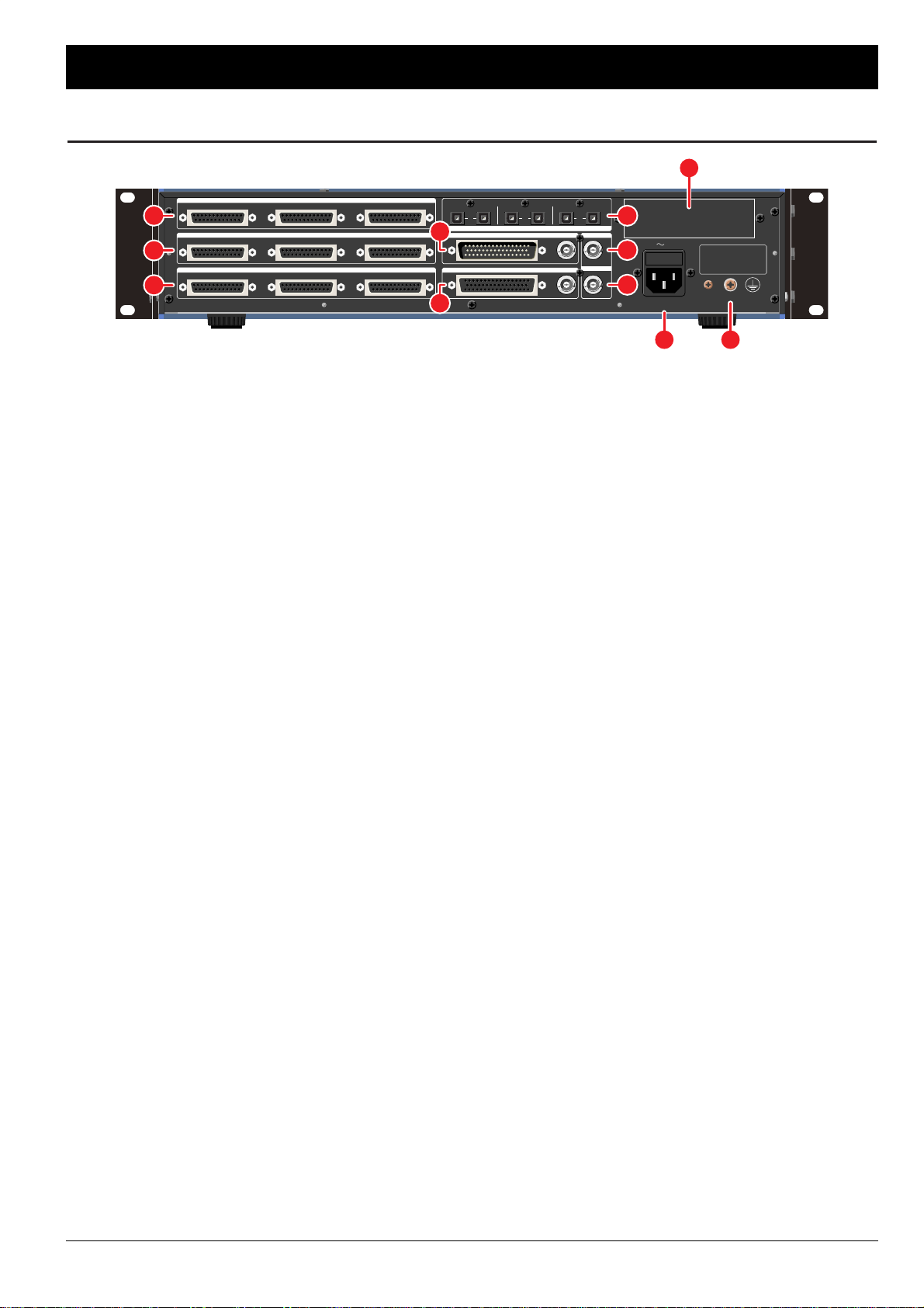
[16] TDIF-1 INPUT/OUTPUT connectors A – C
Used to connect the TDIF-1 signals. The 8 channels of both
inputs and outputs are aligned in a single connector and the FS96 uses three 25-pin D-sub connectors (A – C) for handling a
total of 24 channels.
[17] AES/EBU INPUT connectors A – C
[18] AES/EBU OUTPUT connectors A – C
Used to connect the AES/EBU (AES3) signals. Each connector
handles 8 channels of audio (2-channel stereo pair x 4) and the
FS-96 can handle a total of 24 channels of AES/EBU signals with
three connectors A – C.
[19] ADAT INPUT & OUTPUT connectors A – C
Used to connect the ADAT optical signals. Connections are
made with dedicated optic fiber cables and 8 channels of audio
can be connected with a single cable. The FS-96 provides three
systems of ADAT interfaces for handling a total of 24 channels.
[20] SDIF-2 INPUT connector & SYNC connector
[21] SDIF-2 OUTPUT connector & SYNC connector
Used to connect the SDIF-2 signals. A single 50-pin D-sub
connector (input = male, output = female) is used for connecting
the 24 channels simultaneously. Since the SDIF-2 format requires
a Word Clock signal for synchronization, a SYNC connector (BNC
type) is provided for each of input and output connector.
[22] WORD IN connector
Used to connect an external Word Clock signal which is to be
used as the reference clock signal for the output audio signals.
[23] WORD OUT connector
Used to output the reference clock for the output signals as a
Word Clock signal to external devices.
[24] Option Slot
An expansion slot for adding a new digital audio format to the
FS-96.
[25] AC IN connector
Used to connect the AC power supply to the unit. The fuse
holder is contained in the AC inlet. The power supply circuit of
the FS-96 supports AC voltages and frequencies used all over
the world.
[26] Auxiliary Ground Terminal
Auxiliary ground terminal for the power supply circuit. Use this
terminal when the proper grounding cannot be made with the
AC inlet.
February 2001 7
Controls and Indicators
TDIF-1 INPUT/OUTPUT
ABC
AES/EBU INPUT
ABC
AES/EBU OUTPUT
SDIF-2 INPUT
SDIF-2 OUTPUT
WORD IN
WORD OUT
ABC
ADAT
A B C
INPUT OUTPUT INPUT
SYNC
SYNC
OUTPUT INPUT OUTPUT
CAUTION
FOR CONTINUED PROTECTION
AGAINST RISK OF FIRE,
REPLACE ONLY WITH SAME
TYPE AND RATINGS OF FUSE.
FUSE 3.15A T(SLO) / 250V
IN
100-240V
24
22
23
19
16
17
18
2625
20
21
Rear Panel
Page 8
■ Location for Installation: Choose a well ventilated location
for installing the FS-96. Do not place the unit in a closed rack or
closed boxes. Although the unit is designed to be used in various
temperature environments, be sure to place it away from heat
sources such as heaters, power amplifiers, etc.
NOTES ON OPERATING LOCATION:
• Do not cover the ventilation slots of the unit.
• To prevent damage or short-circuiting of the
internal electronic parts, do not install the
rack in a place where the rack would be
subject to rain, snow, or spills, etc.
• To prevent overheating, do not expose the
unit directly to the sun.
• When installed in a rack, place the rack
at a level and stable location.
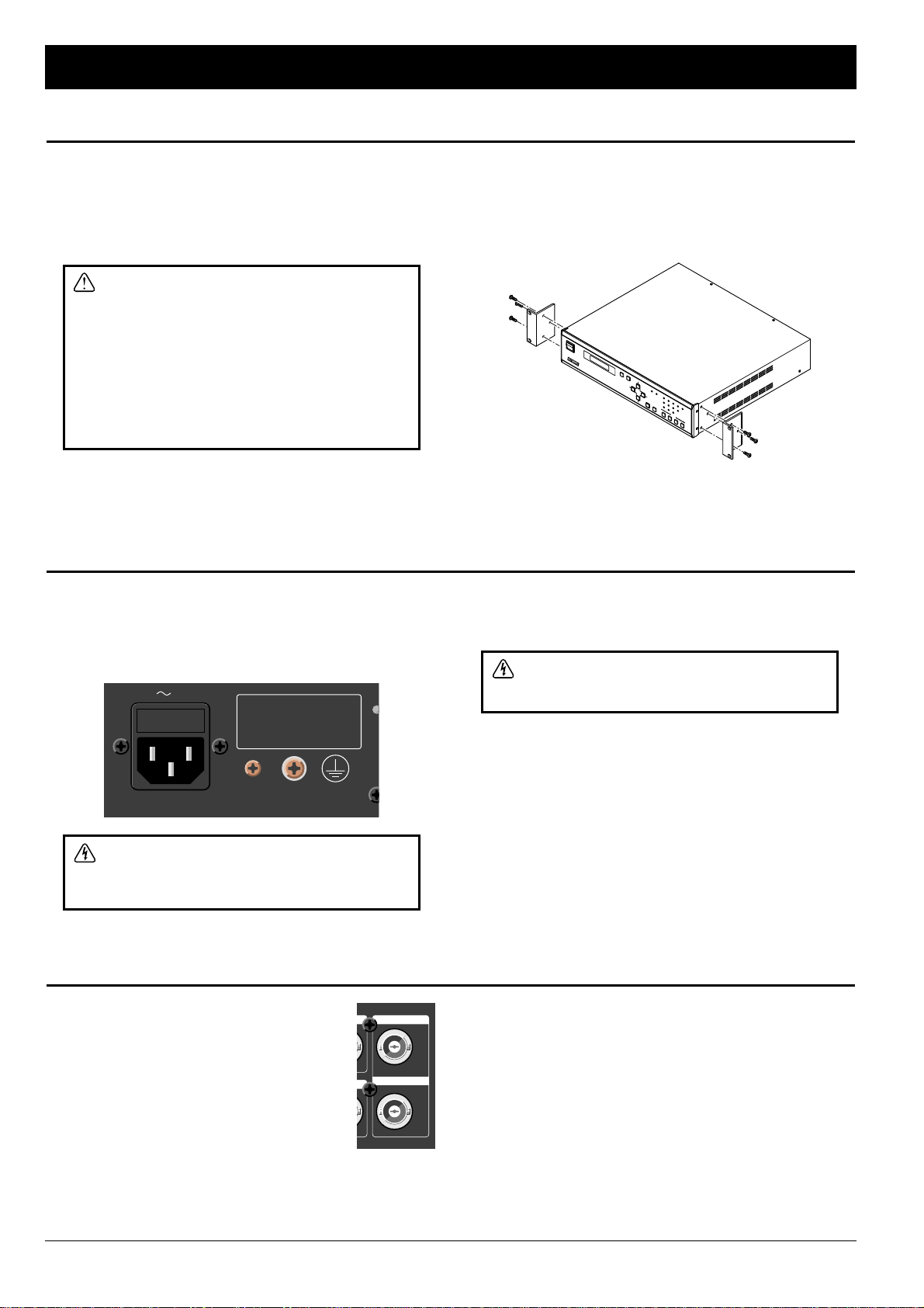
■ Rack/Flight Case Mounting: When mounting the unit in a
rack, remove feet on the bottom panel. Then use the provided
rack mount adapters [KZ2A222-] to mount the FS-96 in the rack.
When securing the unit, we recommend to insert a plastic
washer between the screw and the rack mount adapters to
prevent scarring.
NOTES:
• The rack mount adapters are pre-installed before shipping.
• The FS-96 occupies a 2U rack space.
SETUP RO
UTING
SRC AES EBU
96kHz 48kHz 44.1kHz 32kHz
INT EXT INPUT
ADAT SDIF
2
TDIF
1
OPTIO
N
PRESET
ENTER CANCEL
1
:
1
1234
POW
ER
FORMAT & SAMPLE RATE CONVERTER
FS--96
8 February 2001
Installation and Connection
Installation
Power Supply and Grounding
Connecting Word Clock Signals
■ Connecting AC Power: Use the provided power supply cord
and connect the AC IN connector to the AC mains. The FS-96 is
equipped with a universal power supply circuit which supports
AC voltages (100 – 240 V) and frequencies (50 / 60 Hz) used all
over the world.
CAUTION! To prevent damage to the FS-96
and the connected equipment, do not connect
or disconnect the cables while the machines
are turned on.
■ Grounding: The FS-96 has an auxiliary ground terminal for
the power supply circuit. If no ground terminal exists on the AC
mains, use the ground terminal for proper grounding.
CAUTION! If the machine is not properly
grounded, a high voltage may appear on the
chassis if a short circuit should occur.
NOTE: Confirm that lightning protection equipment is used in the
power supply system of your facility. Also, we recommend to use
a noise filter in the AC mains which is used to provide AC power
to the FS-96, in order to prevent the FS-96 internal circuit from
being damaged by AC line noise, high voltage spikes, surges,
and “brown outs”.
■ Connection of Word Clock Signals:
The FS-96 is equipped with BNC connectors for
interfacing the Word Clock signals. The FS-96
uses the Word Clock signals for synchronizing
with an external device. Connect a coaxial cable
of 75 Ω impedance to the WORD IN or WORD
OUT connector for interfacing the Word Clock
signals.
■ Performing External Synchronization: To synchronize the
output audio signals to the input Word Clock signal, select
“WORD” as the reference lock of the FS-96 in the OUTPUT
SYNC screen in Setup mode (☞ p.18).
NOTE: The reference clock for the output signals is output from
the WORD OUT connector. If the external Word Clock signal is
used as the reference clock, a signal synchronized to the
external Word Clock signal will be output from the WORD OUT
connector. Note that the WORD OUT connector cannot be used
as a “through-out” connector.
WORD IN
WORD OUT
IN
100-240V
FUSE 3.15A T(SLO) / 250V
CAUTION
FOR CONTINUED PROTECTION
AGAINST RISK OF FIRE,
REPLACE ONLY WITH SAME
TYPE AND RATINGS OF FUSE.
Page 9
February 2001 9
Installation and Connection
Connecting ADAT Optical Format Signals
Connecting AES/EBU Format Signals
Connecting SDIF-2 Format Signals
Connecting TDIF-1 Format Signals
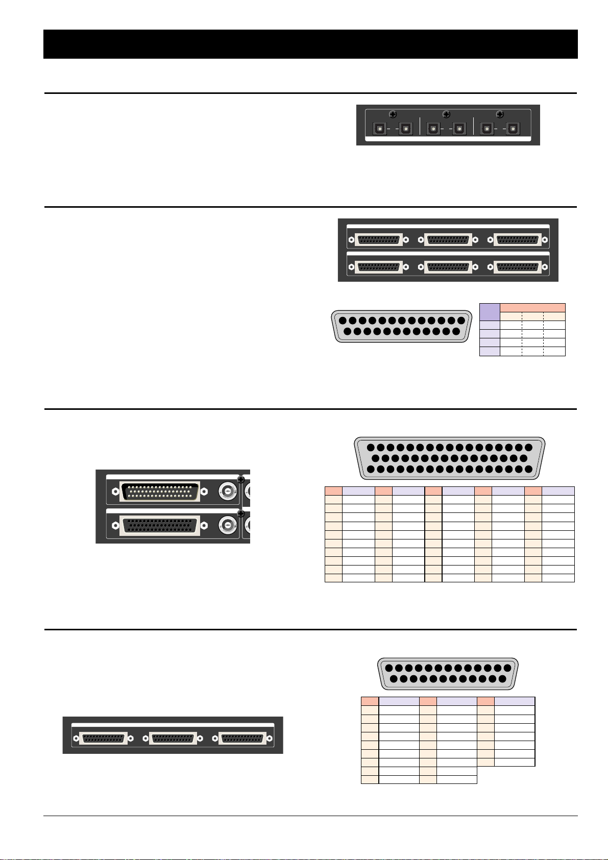
The ADAT optical format uses an optical cable for connecting 8
channels of audio. The FS-96 has three connectors (A – C) for
both input and output to handle a total of 24 channels of ADAT
signals. Each connector corresponds to the following channels
— A = CH1 – 8, B = CH9 – 16, C = CH17 – 24.
ADAT
A B C
INPUT OUTPUT INPUT OUTPUT INPUT OUTPUT
The AES/EBU format uses a D-sub 25-pin female connector for
connecting 8 channels of audio. The FS-96 has three connectors
(A – C) for both input and output to handle a total of 24 channels
of AES/EBU signals. Each connector corresponds to the
following channels — A = CH1 – 8, B = CH9 – 16, C = CH17 –
24. The 8 channels of audio consist of four stereo pairs.
NOTES:
• Use a cable of 110 Ω impedance for connecting the AES/EBU
signals.
• Some manufacturers use different pin assignments for the
AES/EBU connectors. Before connecting, please check for the
pin assignment which is used on the device to be connected.
■ Pin Assignment:
113 3 24657981012 11
1416 151719 182022 212325 24
1–6, 13–19 : NC
CH
PIN
HOT COLD GND
1 / 2 24 12 25
3 / 4 10
23
11
5 / 6 21 9 22
7 / 8 7 20 8
AES/EBU INPUT
ABC
AES/EBU OUTPUT
ABC
The SDIF-2 format uses a single D-sub 50-pin connector (input :
male, output : female) for connecting a maximum of 24 channels
of audio. Note that the Word Clock signal needs to be
connected via the BNC connector for synchronization.
■ Pin Assignment:
1324657981012 11
1820 192123 222426 252728
14 131517 16
3436 353739 384042 414345 4447 464850 49
2931 303233
SIGNALPIN
CH1
(-)
CH1
(
+)
CH2
(
-
)
CH2
(
+)
CH3
(
-
)
CH3
(
+)
CH4
(
-
)
CH4
(
+)
CH5
(
-
)
CH5
(
+)
1
2
3
4
5
6
7
8
9
10
SIGNALPIN
CH6
(-)
CH6
(
+)
CH7
(
-
)
CH7
(
+)
CH8
(
-
)
CH8
(
+)
CH9
(
-
)
CH9
(
+)
CH10
(
-
)
CH10
(
+)
11
12
13
14
15
16
17
18
19
20
SIGNALPIN
CH11
(-)
CH11
(
+)
CH12
(
-
)
CH12
(
+)
CH13
(
-
)
CH13
(
+)
CH14
(
-
)
CH14
(
+)
CH15
(
-
)
CH15
(
+)
21
22
23
24
25
26
27
28
29
30
SIGNALPIN
CH16
(-)
CH16
(
+)
CH17
(
-
)
CH17
(
+)
CH18
(
-
)
CH18
(
+)
CH19
(
-
)
CH19
(
+)
CH20
(
-
)
CH20
(
+)
31
32
33
34
35
36
37
38
39
40
SIGNALPIN
CH21
(-)
CH21
(
+)
CH22
(
-
)
CH22
(
+)
CH23
(
-
)
CH23
(
+)
CH24
(
-
)
CH24
(
+)
N.C.
N.C.
41
42
43
44
45
46
47
48
49
50
SDIF-2 INPUT
SDIF-2 OUTPUT
W
WO
SYNC
SYNC
The TDIF-1 format uses a D-sub 25-pin female connector for
connecting 8 channels of both inputs and outputs. The FS-96
has three connectors (A – C) for the TDIF-1 interface to handle a
total of 24 channels of audio. Each connector corresponds to
the following channels — A = CH1 – 8, B = CH9 – 16, C = CH17
– 24. The 8 channels of audio consist of four multiplexed pairs.
■ Pin Assignment:
113 3 24657981012 11
1416 151719 182022 212325 24
SIGNALPIN
DOUT 1 / 21
2 DOUT 3 / 4
3 DOUT 5 / 6
4 DOUT 7 / 8
5 LRCK OUT
6 FS 0 OUT
7 GND
8 FS 0 IN
9 LRCK IN
10 DIN 7 / 8
11 DIN 5 / 6
12 DIN 3 / 4
13 DIN 1 / 2
SIGNALPIN
GND14
15 GND
16 GND
17 GND
18 EMPH. OUT
SIGNALPIN
19 FS 1 OUT
20 FS 1 IN
21 EMPH. IN
22 GND
23 GND
24 GND
25 GND
TDIF-1 INPUT/OUTPUT
ABC
Page 10
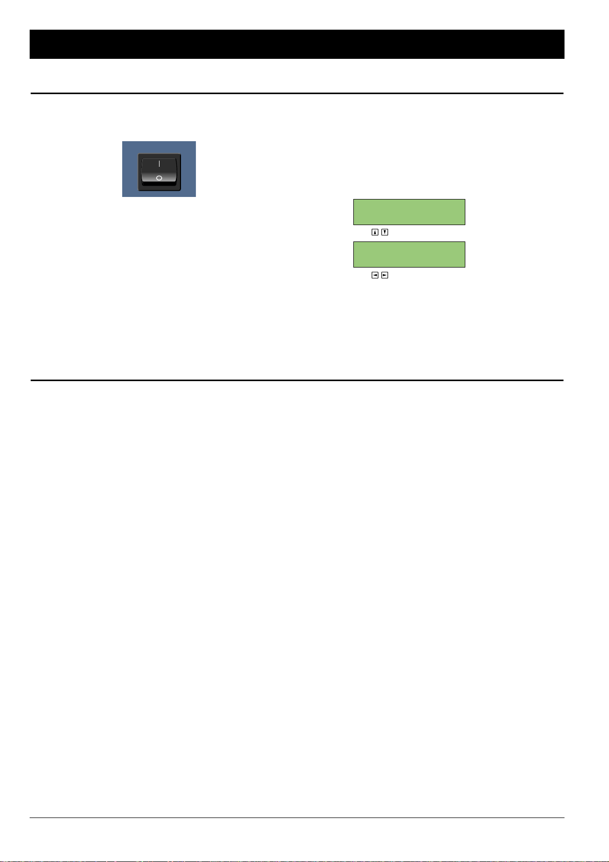
■ Starting Signal Conversion: To turn on the power to the
unit, press the upper part (marked “ I ”) of the POWER switch
located on the front panel.
When the power is applied, all indicators are lit for about 3
seconds and the LCD shows the start-up screen. Then, the initial
screen appears on the LCD and the FS-96 starts to operate.
Note that the FS-96 always stores the current operation settings
and the signal conversion automatically starts with the preset
configurations which were last used.
NOTE — Using FS-96 as a Turn-key System: If the
connections and configurations are properly made, the FS-96
can be started up by merely turning on the system. This means
that the system can be used as a turn-key system.
■ Display of Initial Screen: On the initial screen of the LCD,
you can check for the numbers of the preset memories which
are currently being used. The FS-96 operates according to the
settings stored in the setting and routing memories. By pressing
the upper & lower Arrow keys, you can change the LCD screen
as follows. In another page of the initial screen, you can check
for the information for the input and output signals.
■ INITIAL SCREENS:
(USE TO CHANGE SCREENS)
(USE TO CHANGE DISPLAY RANGE)
←
INFO. FOR INPUTS
←
INFO. FOR OUTPUTS
FI: 1/2 -----K
FO: 1/2 96.00K
←
SETTING MEMORY No.
←
ROUTING MEMORY No.
SETTING MEM.: 0
ROUTING MEM.: 0
10 February 2001
Basic Operation
Powering Up
Basic Setup Instructions
1. Press SETUP Button, to access menu items below.
2. Select INPUT FORMAT (ADAT, AES, BDIR, TDIF, SDIF,
OPTION).
• Channel Grouping: All digital formats above are grouped
in 8 channel groups except for SDIF-2 which is grouped in
a single 24 channel group on a 50-pin connector (Group
A: 1–8, Group B: 9–16, Group C: 17–24).
• Imbedded Sync Signal: Clocks (sync) for ADAT, AES,
BDIR, and TDIF are imbedded in the audio bitstreams for
their respective formats.
• SDIF-2 Synchronization: For synchronizing SDIF-2, use
the SYNC BNC connectors on the rear panel of the FS-96
(SYNC Input or SYNC Output), located to the right of the
50 pin SDIF-2 connectors.
3. Select OUTPUT SYNC (<INTERNAL>, EXTERNAL,
INPUT).
• BNC Sync connectors: The Word Clock IN and OUT
BNC connectors are for OUTPUT SYNC only.
• If OUTPUT SYNC = INTERNAL
• Select FS SETTING (sample rate = 32K, 44.1K, <48K>,
64K, 88K, 96K)
• If OUTPUT SYNC = INPUT
• If Input Format = AES (Select Sync Group choice:
<CH1/2>, CH3/4, or CH5/6…CH23/24)
• If Input Format = ADAT, TDIF, BDIR (Select Sync Group
choice: <GRPA>, GRPB, or GRPC)
4. Select SAMPLE RATE CONVERT <ON>, for sample rate
conversion.
5. Select OUTPUT RESOLUTION (16BITS, 20BITS,
<24BITS>).
The FS-96 automatically detects the bit resolution of the
input signals. Normally, the bit resolution of the input signals
is selected in this screen.
6. Select DITHER as required (ON, <OFF>).
This is usually used for down-conversion of sample rates
(such as down-converting from 48k to 44.1k).
7. Set OUTPUT STATUS as required.
The following settings are possible.
• AES/EBU EMPH.: OFF, THRU, 5010, CCIT)
• AES/EBU FREQ.: THRU, 32K, 44K, 48K, AUTO
• SDIF EMPH.: THRU, ON, OFF
• TDIF EMPH.: THRU, ON, OFF
• TDIF BIT RES.: THRU, 16, 20, 24
• TDIF FREQ.: THRU, 32K, 44K, 48K, OTHER
8. Set SYNC TIMING as required for digital lock.
• INPUT DELAY A, B, or C (-2, -1, 0, +1, +2) to adjust clock
reference
• TDIF OUTPHASE: 0 (-2, -1, 0, +1, +2) to adjust LRCK
framing.
POWER
Page 11
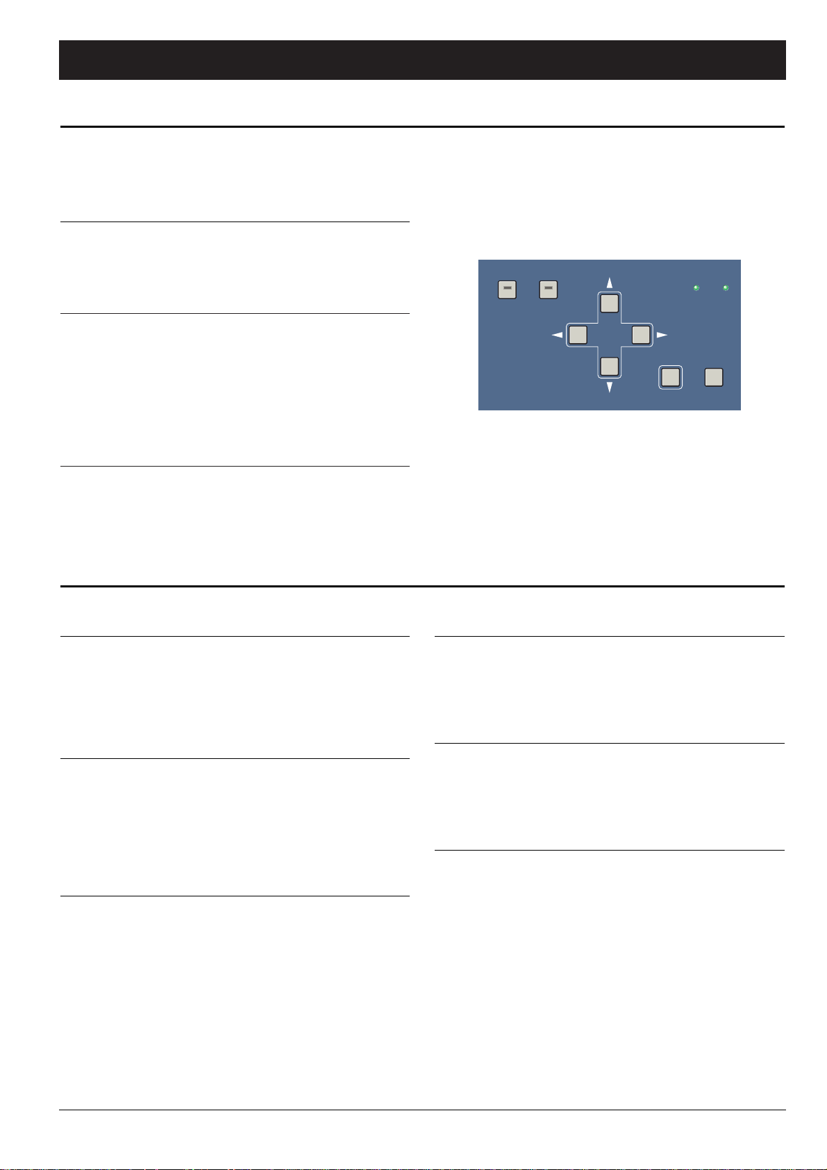
■ Basic Operations: The operation of the FS-96 is controlled
by the parameters set on the LCD. The procedure for setting
parameters is fully menu-driven and the selection is made with
the Arrow keys, in conjunction with the ENTER and CANCEL
keys.
■■ Changing LCD Screens: Each mode consists of multiple
LCD screens and the screens can be changed by pressing the
upper & lower Arrow keys. When a screen is displayed, press
the ENTER key to select a parameter on the screen. To
release the selection, press the CANCEL key.
■■ Changing Parameter Values: When a parameter is
selected, the value for that parameter is displayed with
parentheses ( <>). At this point, you can change the
parameter value by pressing the right & left Arrow keys.
If many choices are available for that parameter, use the upper
& lower Arrow keys to change the value in larger increments.
After the desired value is entered, press the ENTER key again
to store the value into the current memory and to reflect the
setting onto the actual operation.
NOTE: The actual operation is changed by altering the internal
circuit configurations. It may take a few seconds until the settings
are reflected onto the actual operation.
■ Cancelling Parameter Changes: If a parameter does not
need to be changed, you can return the parameter value by
pressing the CANCEL key. When the CANCEL key is pressed,
the parameter selection is released and the parameter value will
be returned to the status when the ENTER key is last pressed.
Note that, if a value is already stored by pressing the ENTER key,
that value cannot be returned to the previous value.
NOTE: The configuration modes (Setup and Routing modes)
cannot be released when a parameter is selected in a setting
screen. Press the CANCEL (or ENTER) key to release the
selection and then press the SETUP or ROUTING key to leave
the configuration mode.
SETUP ROUTING
SRC
ENTER CANCEL
1:1
February 2001 11
Basic Operation
Operations with LCD
Modes of Operation
■ Operation Modes: The FS-96 operates in either of the
following two conversion modes.
■■ Normal Mode: This mode is used to convert the format and
sample rate of the 24 channels of digital audio. The input
digital audio signals will be converted to all of the signal
formats available on the FS-96.
When the FS-96 is in Normal mode, all advanced functions
are available such as the sample rate conversion, change of
bit resolution, signal routing, etc.
■■ Bi-Direction Mode (☞ p.25): This mode is used to perform
the bi-directional format conversions between the TDIF-1 and
AES/EBU interfaces. Bi-Direction mode is prepared for
situations such as connecting a digital audio recorder having a
TDIF-1 interface with a digital mixing console having an
AES/EBU interface.
In this mode, the advanced functions such as sample rate
conversion or signal routings are not available.
Selection of the operation mode is made by changing the input
format. If the input format is set to “BDIR”, the FS-96 is set to BiDirection mode. If the input format is set to a format other than
“BDIR”, the FS-96 is placed in Normal mode.
NOTE: The FS-96 operates according to the settings stored in
the preset memories. The FS-96 always stores current preset
memory numbers when the power is turned off and the same
memory numbers are used when the power is turned back on.
■ Configuration Modes: The operation settings are made in
two configuration modes — Setup and Routing modes.
■■ Setup Mode (☞ p.16–23): The system settings excluding the
routing settings are made in Setup mode. To place the FS-96
into Setup mode, press the SETUP key on the front panel so
that the key’s indicator illuminates. Pressing the SETUP key
again causes the key’s indicator to go off and the FS-96 to
leave Setup mode.
■■ Routing Mode (☞ p.24): Routing mode is used only for
configuring signal routing settings. To place the FS-96 into
Routing mode, press the ROUTING key on the front panel so
that the key’s indicator illuminates. Pressing the ROUTING key
again causes the key’s indicator to go off and the FS-96 to
leave Routing mode.
NOTE: The operation settings can be stored into 10 preset
memories and the preset settings can be used by recalling the
memories. Please refer to the “Operating Memories” section
for the details of preset memories (☞ p.13–15).
Also, combinations of setting and routing memories can be
stored to the PRESET keys on the front panel. Please refer to the
“Using PRESET Keys” section for the usage of the PRESET
keys (☞ p.15).
Page 12
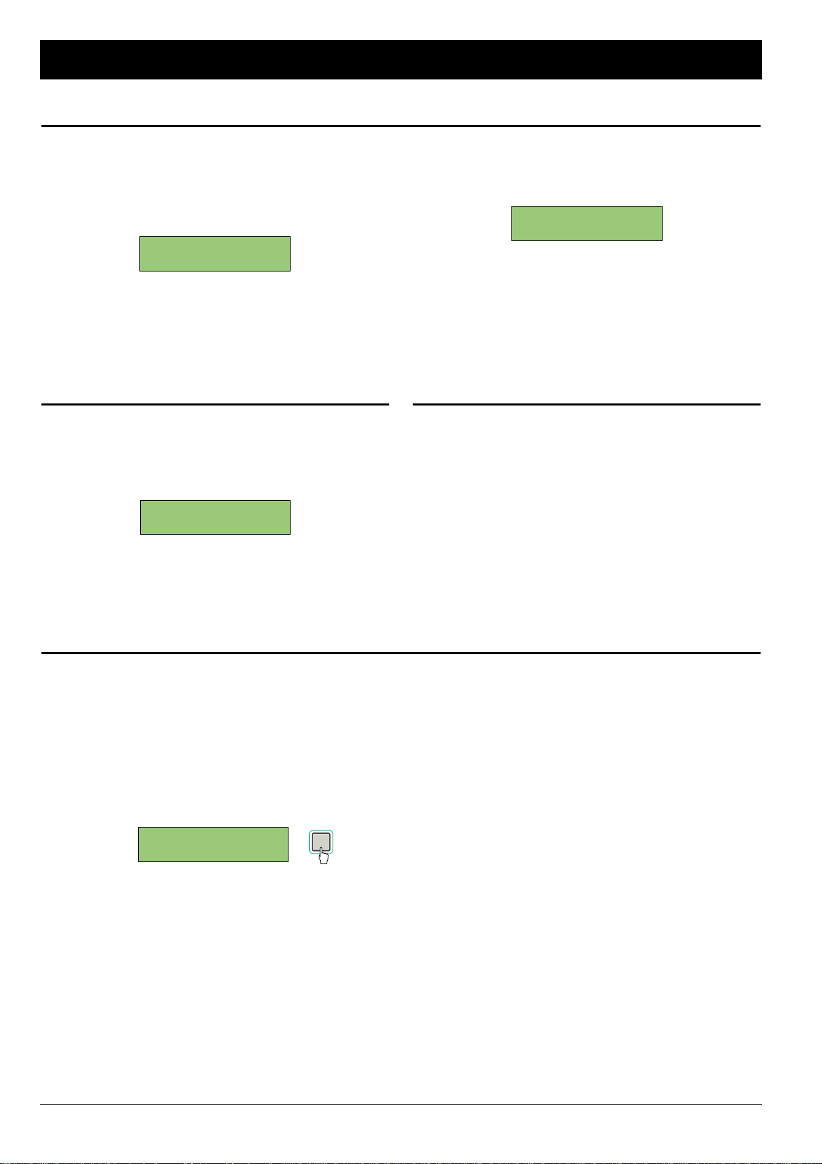
All parameters can be reset to the factory settings by initializing
the system memory of the FS-96. To initialize the system
memory, hold the CANCEL key pressed and turn on the power
to the FS-96. The following screen appears for about 5 seconds
to indicate that all settings are reset to the default values.
■ RESET SCREEN
After the system memory is initialized, the following screen
appears after powering up to indicate that no setting data is
present on the system memory.
■ NO SETTING DATA ON MEMORY
NOTE — Replacing Backup Battery: If the above screen
appears every time the power is turned on and the stored
settings are lost, the backup memory may be dead. In this case,
please contact your Otari dealer for replacement of backup
batteries.
NOTE:
NO SETTING DATA
ALL SETTINGS ARE
RESET TO DEFAULT
12 February 2001
Basic Operation
Resetting All Settings
Mis-synchronization due to Additional Signal Connection
If a signal cable is additionally connected to the current input
format, or if all connectors are disconnected and then reconnected, the phase-level synchronization of the input signals
will be lost. In this case, the following screen appears on the LCD
to alert the operator, since the signal synchronization cannot be
obtained on the destination machines, even if there are no
audible problems. When this screen is displayed, press the
ENTER key to reset the synchronization circuit and to return to
the proper operation status.
■ PHASE ERROR SCREEN
ENTER
PHASE ERROR
RESET FS-96?<OK>
Using Key Lock Function
To avoid accidental changes in the system settings, the
operations of the FS-96 can be locked by holding the ENTER
key down in the initial screen. The following appears when the
operation is locked.
■ KEY LOCK SCREEN
To release the key lock, simply hold the ENTER key pressed until
the LCD shows the initial screen.
Considering Signal Delay
Since the FS-96 handles all audio signals in digital fields, please
be aware that some delay is applied to all signals by passing
through the FS-96. Although the amount of signal delay varies
due to the signal formats, normally the delay between the input
and output will be 2 to 3 samples.
KEY LOCKED. HOLD
ENTER TO RELEASE
Page 13
■ Setting and Routing Memories: The FS-96 has two
configuration modes consisting of Setup mode and Routing
mode, and the preset memories are provided for each of the
configuration modes — setting memories and routing memories.
All system settings for the FS-96 are stored in these preset
memories. The setting memories are used to store the operation
settings made in Setup mode, excluding the signal routing
configurations. Also, the routing memories are used only to store
the signal routing settings made in Routing mode.
10 preset memories (No. 0 – 9) are provided for each of the
configuration modes and the operation settings can be altered
momentarily by changing the memory number selections. Since
the setting and routing memories can be selected separately, it is
possible to change the signal routing settings while the same
operation settings are maintained. Also, it is possible to change
the system settings while the same routing settings are
maintained.
NOTE: Combinations of setting and routing memories can be
stored to the PRESET keys on the front panel. Please refer to the
“Using PRESET Keys” section for the usage of the PRESET
keys (☞ p.15).
■ Display of Current Preset Memories: The initial screen
displays the preset memory numbers that are currently used.
Note that the changes made in the configuration modes will be
stored into the preset memories which are currently used. When
changing the operation parameters, confirm that the desired
memory numbers are displayed on the initial screen. See the
“Recalling Preset Memories” section on this page for the
details of recalling preset memories.
■ INITIAL SCREENS:
NOTE: The contents of the preset memories will be updated
every time a parameter value is stored. It is recommended to
copy the memory contents before making large changes to the
various settings.
←
SETTING MEMORY No.
←
ROUTING MEMORY No.
SETTING MEM.: 0
ROUTING MEM.: 0
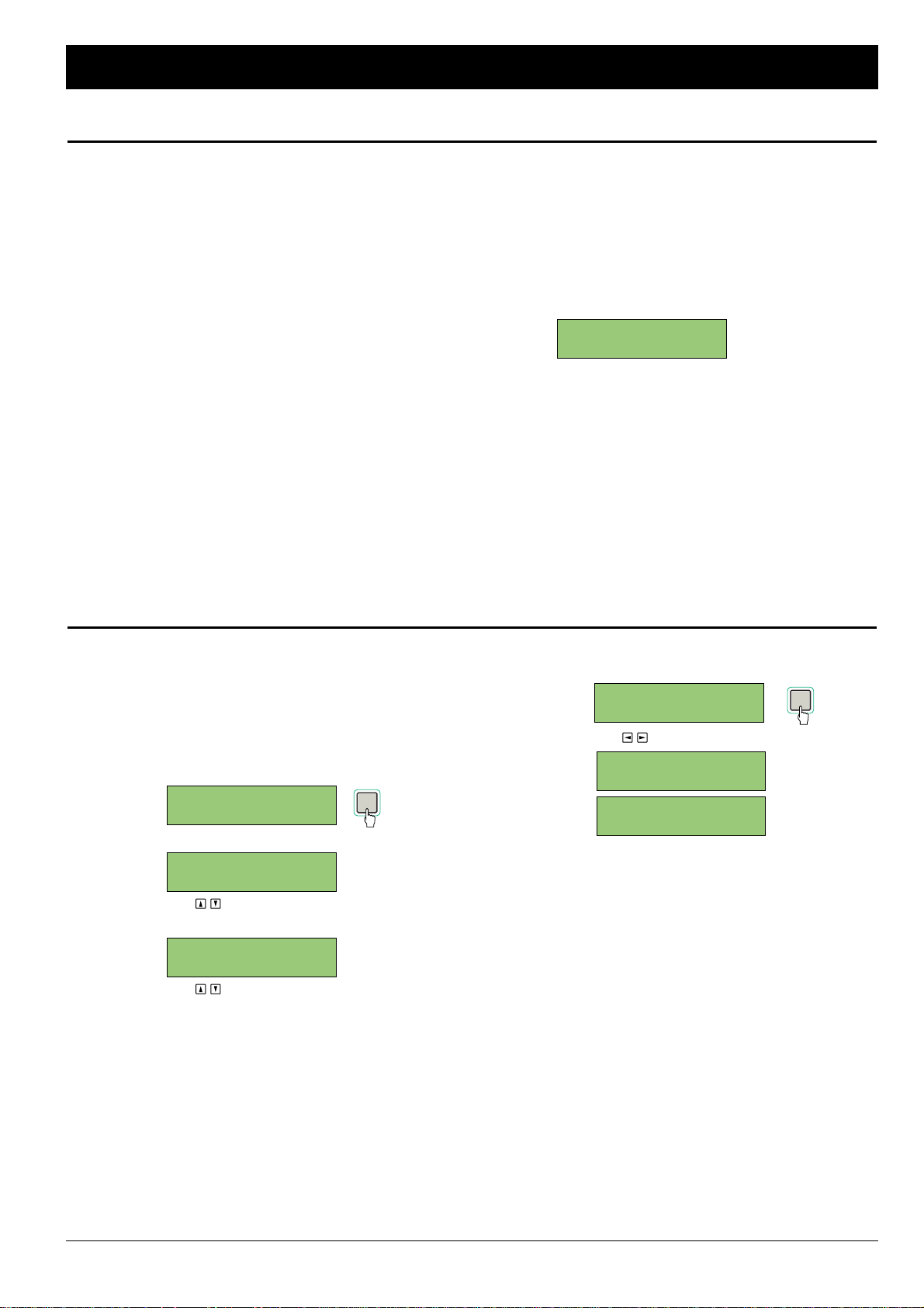
To change the preset memories to be used, follow the
instructions below to recall the desired memory numbers.
1. Press the ENTER key in the initial screen and select the
number of setting or routing memories.
The setting memory number is displayed with parentheses.
To select the routing memory number, press the Upper or
Lower Arrow keys.
■ SELECTING SETTING MEMORY
(USE TO MOVE SELECTION)
■ SELECTING ROUTING MEMORY
(USE TO MOVE SELECTION)
2. Use the right & left Arrow keys to select the desired
memory number and press the ENTER key to store.
(USE TO CHANGE MEMORY NUMBER)
It may take a few seconds until the settings are changed
and the LCD shows “WAIT A MOMENT...” during this time.
SETTING MEM.: 1
ROUTING MEM.: 0
WAIT A MOMENT...
SETTING MEM.:<1>
ROUTING MEM.: 0
SETTING MEM.: 0
ROUTING MEM.:<0>
SETTING MEM.:<0>
ROUTING MEM.: 0
SETTING MEM.: 0
ROUTING MEM.: 0
February 2001 13
Operating Memories
Using Preset Memories
Recalling Preset Memories
ENTER
ENTER
Page 14
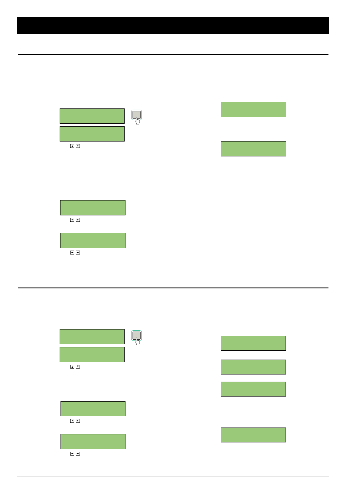
The contents of each preset memory can be duplicated into the
other memory numbers. This function is useful when you make
important changes, or when it becomes necessary to prepare
two or more similar settings.
1. Press the ENTER key in the initial screen and select the
setting or routing memory number.
(USE TO MOVE SELECTION)
2. Hold the ENTER key pressed until the following screen
appears on the LCD. Then, use the right & left Arrow
keys to select the destination memory number to which
the contents of the current memory number will be
copied.
■ COPYING SETTING MEMORY
(USE TO CHANGE MEMORY NUMBER)
■ COPYING ROUTING MEMORY
(USE TO CHANGE MEMORY NUMBER)
3. Press the ENTER key to store the destination memory
number.
The contents of the current memory number are copied to
the destination memory number.
The LCD returns to the initial screen, with the destination
memory number selected.
4. To use the destination memory number, press the
ENTER key to release the memory number selection.
SETTING MEM.: 1
ROUTING MEM.: 0
SETTING MEM.:<1>
ROUTING MEM.: 0
ROUTING COPY:
0 => < 1 >
SETTING COPY:
0 => < 1 >
SETTING MEM.:<0>
ROUTING MEM.: 0
SETTING MEM.: 0
ROUTING MEM.: 0
14 February 2001
Operating Memories
Duplicating Preset Memories
Clearing Preset Memories
The contents of each memory number can be cleared in the
following manner.
1. Press the ENTER key in the initial screen and select the
setting or routing memory number.
(USE TO MOVE SELECTION)
2. Hold the CANCEL key pressed until the following
screen appears on the LCD.
■ RESETTING SETTING MEMORY
(USE TO SELECT YES OR NO)
■ RESETTING ROUTING MEMORY
(USE TO SELECT YES OR NO)
3. To clear the contents of the selected memory number,
select “YES” and press the ENTER key.
The following screen appears for about one second. Then,
the LCD returns to the initial screen, with the memory
number selected.
■ RESETTING SETTING MEMORY
■ RESETTING ROUTING MEMORY
4. If the reset memory number is to be used, press the
ENTER key to store the memory number selection.
The selection of the memory number will be released.
SETTING MEM.: 0
ROUTING MEM.: 0
SETTING MEM.:<0>
ROUTING MEM.: 0
ROUTING RESET
...DONE.
SETTING RESET
...DONE.
RESET MEM. 0 TO
1:1? <YES> NO
RESET MEM. 0 TO
DEFAULT?<YES>NO
SETTING MEM.:<0>
ROUTING MEM.: 0
SETTING MEM.: 0
ROUTING MEM.: 0
ENTER
ENTER
Page 15
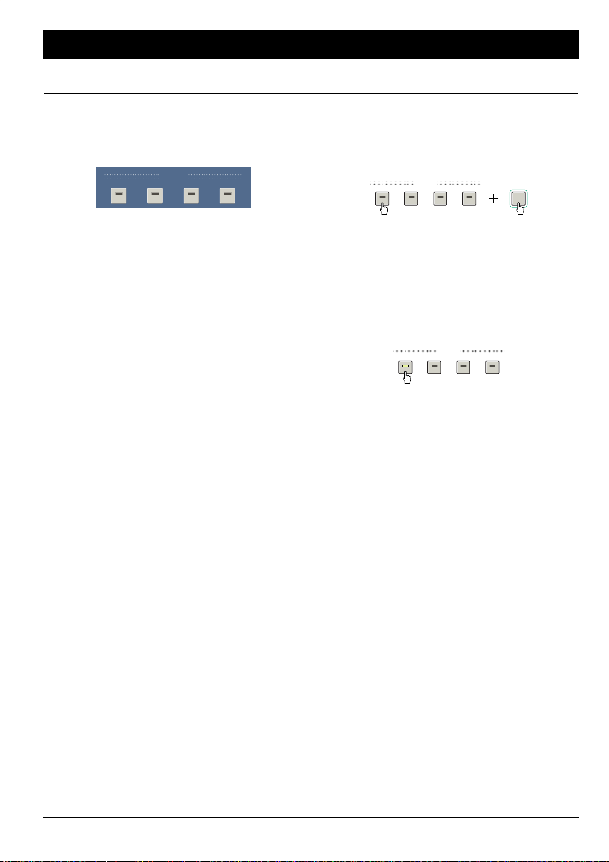
■ About PRESET Keys: The four PRESET keys on the front
panel are used to store combinations of setting and routing
memory numbers. Once a memory combination is stored in a
PRESET key, both the setting and routing configurations can be
changed simultaneously by pressing the PRESET key.
NOTE: Only the combinations of memory numbers are stored in
the PRESET keys. Thus, if changes are onto the contents of the
preset memory stored in a PRESET key, pressing the PRESET
key recalls the changed memory contents.
■ Illumination of PRESET Keys: The indicator in a PRESET
key is lit only when the preset is being used. Thus, the indicator
in the PRESET key will go off when the memory number of the
setting or routing memory is changed after the preset memory is
recalled.
■ Storing into a Preset: To store the current combination of
the setting and routing memories, hold the desired PRESET key
down and press the ENTER key. When the memory combination
is stored, the indicator in the PRESET key illuminates to indicate
that the memory combination stored in the PRESET key is
currently being used.
NOTE: Each PRESET key stores the setting and routing memory
numbers “0” as default values.
■ Recalling a Preset: To recall the memory combination stored
in a PRESET key, simply press the desired PRESET key. The
setting and routing memories will be changed to the combination
stored in the PRESET key and the current memory numbers are
displayed on the initial screen. It may take a few seconds until
the actual settings are changed and the LCD shows “WAIT A
MOMENT...” during this time.
PRESET
1234
ENTER
PRESET
1234
PRESET
1234
February 2001 15
Operating Memories
Using PRESET Keys
Page 16
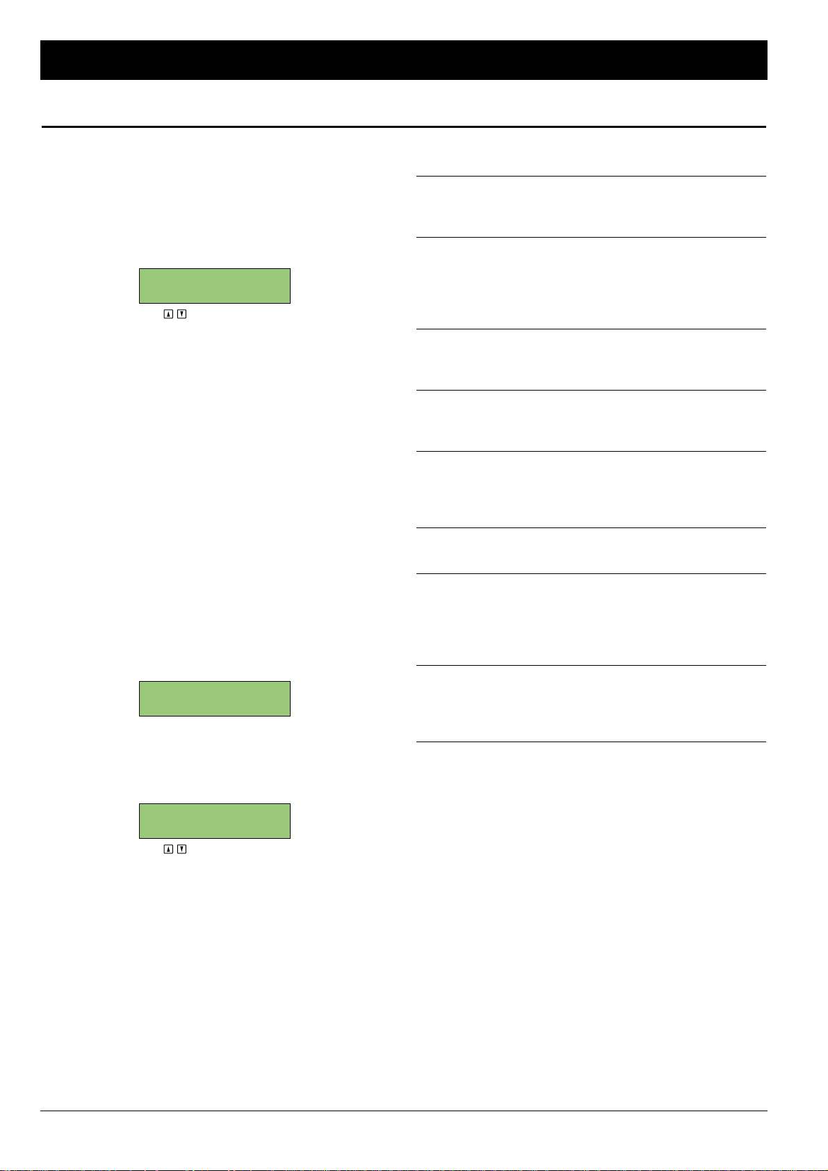
■ About Setup Mode: Setup mode is used to make all
operation settings excluding the signal routing configurations. To
place the FS-96 into Setup mode, press the SETUP key so that
the key’s indicator illuminates. When the FS-96 is in Setup
mode, the current operation settings are displayed in the LCD
screens and the screens can be changed by pressing the upper
& lower Arrow keys.
■ SETUP MODE INITIAL SCREEN
(USE TO CHANGE SCREEN)
NOTE: To leave Setup mode, press the SETUP key again so
that the key’s indicator goes off. If you are to move the FS-96
from Setup mode to Routing mode, you must leave Setup mode
before pressing the ROUTING key.
■ Using Setting Memories: The FS-96 utilizes two preset
memories consisting of the setting memories and routing
memories. The setting memories are used to store the settings
made in Setup mode and a total of 10 preset memories (No. 0 –
9) are provided for the setting memories. Note that the changes
made in Setup mode will be stored into the setting memory
which are currently selected. Before you make any changes to
the settings, confirm that the desired preset memory number is
displayed on the initial screen.
■ Operations in Setup Mode: The setting operations in Setup
mode are made in the following manner.
1. Select the desired setting memory number on the initial
screen.
The settings made in Setup mode will be stored into the
setting memory currently being used.
2. Press the SETUP key to enter Setup mode.
The settings stored in the current setting memory will be
displayed on the LCD. The LCD screens can be changed by
pressing the upper & lower Arrow keys.
(USE TO CHANGE SCREEN)
3. Make the desired settings in the Setup mode screens.
Please refer to the following pages for the details of each
screen. When a parameter value is stored by pressing the
ENTER key, that setting will be stored into the current
setting memory and the actual setting will be changed.
4. After all of the desired settings are finished, press the
SETUP key to leave Setup mode and return to the initial
screen.
■ Setup Mode Screens: Setup mode consists of the following
screens.
■■ INPUT FORMAT screen (☞ p.17): used to select the input
signal format. This screen is also used when placing the FS-96
into Bi-Direction mode.
■■ OUTPUT SYNC screen (☞ p.18): used to select the
synchronization signal (“reference clock signal”) for the output
audio signals. The reference clock can be selected from three
types of signals — FS-96’s internal clock signal, external Word
Clock signal, and input audio signal.
■■ SAMPLE RATE CONVERT screen (☞ p.19): used to select
whether the sample rate converter is applied to the output
audio signals.
■■ OUTPUT RES. screen (☞ p.20): used to select whether to
change the bit resolution (number of quantization bits) of the
output audio signals.
■■ DITHER screen (☞ p.20): used to select whether to apply
the dither function to the audio data. Note that the dither
function is needed only when the bit resolution is changed in a
decreasing direction.
■■ OUTPUT STATUS screen (☞ p.21): used to edit the status
data contained in the output audio signals.
■■ SYNC TIMING screen (☞ p.22): used to change the
sampling timing for the input audio signals, by applying some
delay to the clock signal extracted from the input audio
signals. Also, the output timing of TDIF-1 signals for the
WORD CLOCK signal can be adjusted.
■■ LCD CONTRAST screen (☞ p.23): used to adjust the
contrast for the LCD screen. This setting is separate from the
setting memories and a single setting is stored in the system
memory.
NOTE: The current setting memory number is displayed in the
upper right corner of each LCD screen.
NOTE — Blinking of SETUP Key: Normally, the indicator in the
SETUP key illuminates when the FS-96 is in Setup mode and the
changes made in Setup mode will be reflected instantly by
pressing the ENTER key. However, some operation parameters
may take a few seconds until the changes are reflected in the
actual settings. In this case, the SETUP key’s indicator will
continue to flash to indicate that an operation parameter is
currently being changed, until the change takes effect.
INPUT FORMAT:
AES
SETTING MEM.: 0
ROUTING MEM.: 0
INPUT FORMAT:
AES
16 February 2001
Setup Mode
Operations in Setup Mode
Page 17
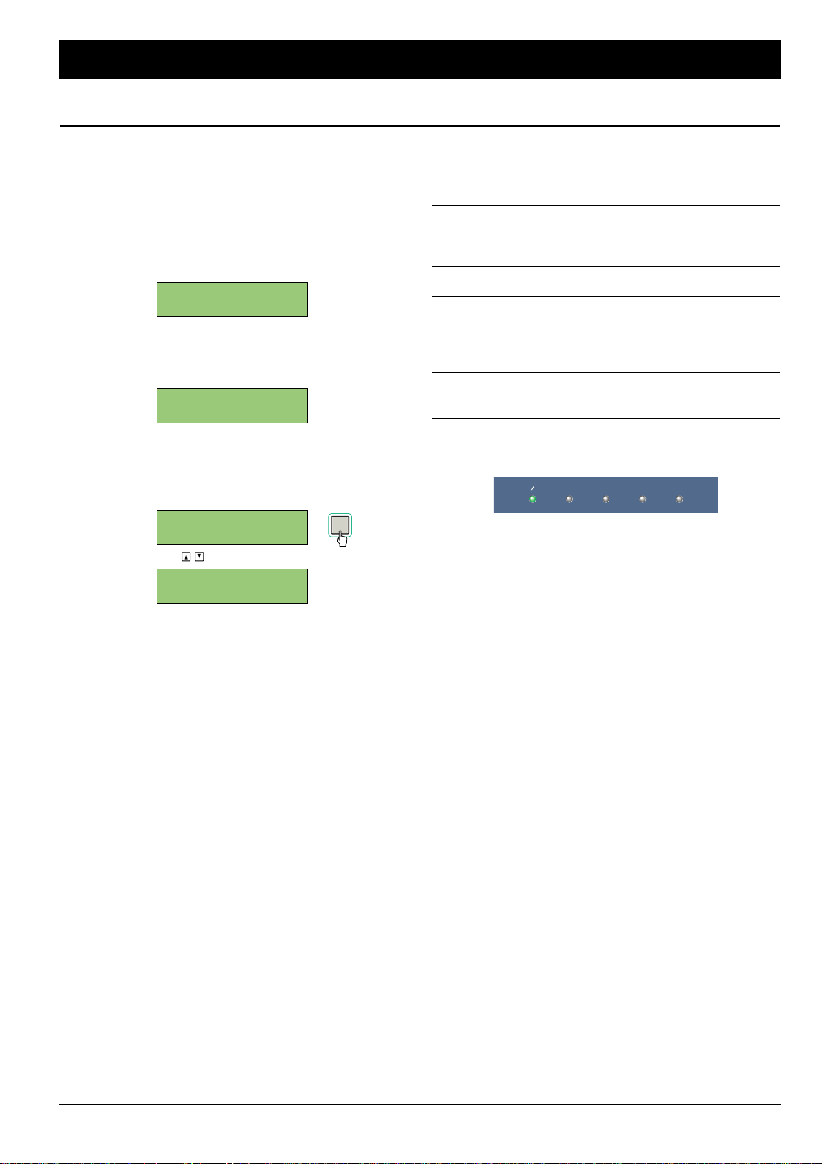
The FS-96 can handle a maximum of 5 digital audio formats
(ADAT, AES/EBU, SDIF-2, TDIF-1, OPTION). The signals input in
the selected format will be converted to all of the formats
available on the FS-96.
1. Press the SETUP key to place the FS-96 in Setup mode
and select the INPUT FORMAT screen by pressing the
upper & lower Arrow keys.
The current input format is displayed.
2. Press the ENTER key to activate the parameter.
The current selection is displayed with parentheses and the
other choices are displayed on the screen.
3. Select the desired format with the right & left Arrow
keys and press the ENTER key to store the selection.
The selection is stored into the current setting memory and
is reflected onto the actual setting.
(USE TO SELECT INPUT FORMAT)
■ List of Input Formats: The following input formats are
available in the INPUT FORMAT screen.
■■ AES: selects the AES/EBU (AES3) format.
■■ ADAT: selects the ADAT optical format.
■■ SDIF: selects the SDIF-2 format.
■■ TDIF: selects the TDIF-1 format.
■■ BDIR: used to place the FS-96 in Bi-Direction mode to
perform bi-directional conversions between the TDIF1 and AES/EBU formats. Please refer to “Using Bi-
Direction mode” for details (☞ p.25).
■■ OPT: selects the signal format of an expansion module
inserted in the option slot.
■ Indication of Input Format: The selection of the input format
will be displayed by the Source indicators on the front panel.
If no signal is present or if no synchronization is achieved for the
input signals, the source indicator will flash to alert the operator.
NOTE: When “BDIR” (Bi-Direction mode) is selected, both the
AES/EBU and TDIF-1 indicators are illuminated.
AES EBU ADAT SDIF-2 TDIF-1 OPTION
INPUT FORMAT: 0
ADAT
INPUT FORMAT: 0
AES <ADAT> SDIF
INPUT FORMAT: 0
BDIR < AES> SDIF
INPUT FORMAT: 0
AES
February 2001 17
Setup Mode
Selecting Input Format
ENTER
Page 18
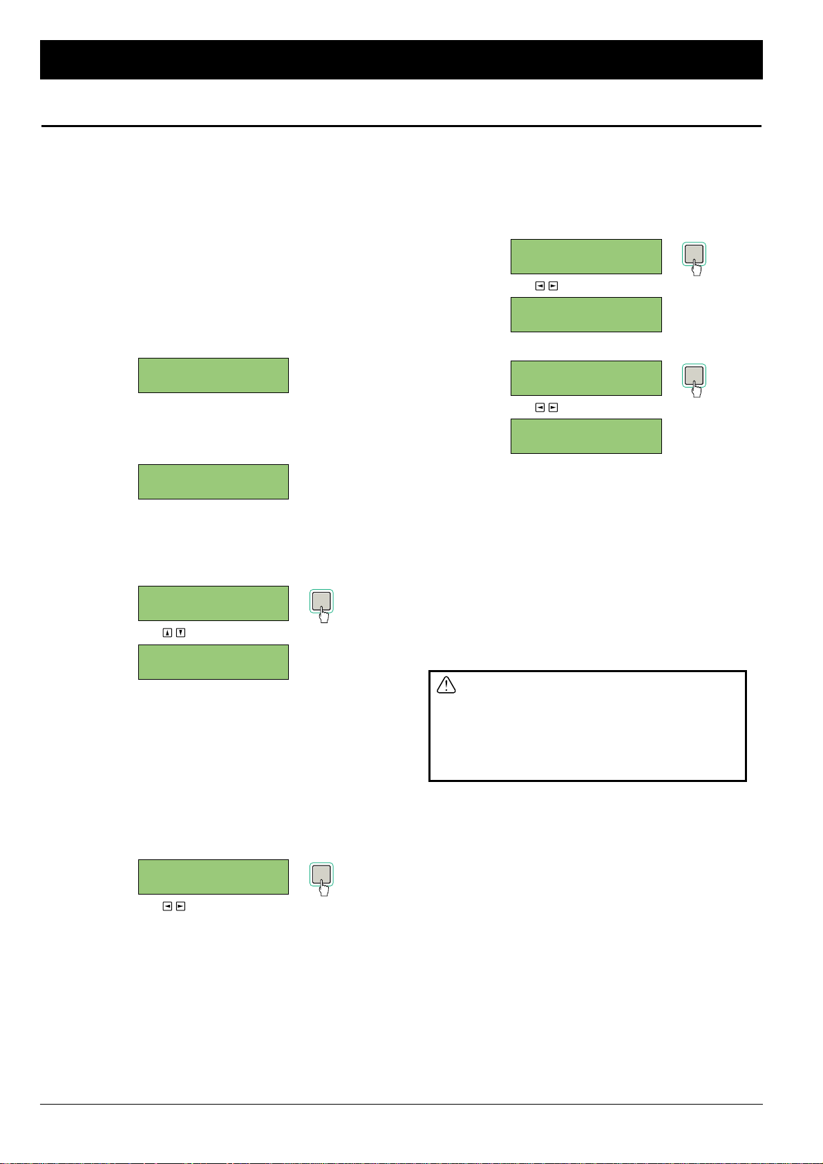
The reference clock (synchronization source) signal is used to
determine the sample rate and synchronization status of the FS-
96. The sample rate of the audio signals will be changed to the
frequency of the reference clock signal. Also, the output audio
signals will be in synchronization to the reference clock signal in
a phase accuracy.
1. Press the SETUP key to place the FS-96 in Setup mode
and select the OUTPUT SYNC screen by pressing the
upper & lower Arrow keys.
The current reference clock is displayed on the screen.
If the internal clock signal (“INT”) is used, the screen shows
the signal frequency. If the input audio signal (“INPUT”) is
used, the screen shows the input signal group.
2. Press the ENTER key to activate the parameter.
The current selection is displayed with parentheses and the
other choices are displayed on the screen.
3. Select the desired signal with the right & left Arrow keys
and press the ENTER key to store the selection.
The selection is stored into the current setting memory and
is reflected onto the actual setting.
(USE TO SELECT SIGNAL)
When in internal clock signal (“INT”) or input audio signal
(“INPUT”) is selected, the LCD changes to the optional
screen.
NOTE — SRC Setting on Reference Clock Selection: If the
sample rate converter (SRC) is turned off, attempting to change
the reference clock to a signal other than the input signal (IPT or
INPUT) causes the following screen to appear on the LCD. In this
screen, you can activate the SRC instantly by choosing “YES”.
After the desired option is selected, press the ENTER key to
change the status of the SRC.
(USE TO SELECT YES / NO)
4. When “INT” is selected, select a frequency of the signal
and press the ENTER key.
When “INPUT” is selected, select a input signal group
and press the ENTER key.
The LCD returns to the OUTPUT SYNC screen.
■ FREQUENCY SELECTION FOR INTERNAL CLOCK
(USE TO SELECT FREQUENCY)
■ GROUP SELECTION FOR INPUT SIGNAL
(USE TO SELECT GROUP)
The choices in the GROUP SETTING screen vary with the
selection of the input format. When the AES/EBU format is
used, selection is made for 12 channel pairs (1/2 ch – 23/24
ch). When the ADAT or the TDIF (including Bi-Direction
mode) is used, selection can be made for three groups
(GROUP A – C). There is no group selection for the SDIF
format.
After the optional settings are made, press the CANCEL key
to return to the OUTPUT SYNC screen. You cannot move to
the other screens, once you return to the OUTPUT SYNC
screen.
If the reference clock is set to a signal other
than the input audio signal (or the external
Word Clock signal synchronized to the input
audio signal), be sure to turn on the sample
rate converter. If the sample rate converter is
not activated, proper audio signals may not be
output.
NOTE: When “BDIR” (Bi-Direction mode) is selected as the input
format, the reference clock will be changed automatically to the
group A of the TDIF-1 input.
OUTPUT SYNC: 0
INPUT 1/2ch
GROUP SETTING: 0
24 < CH1/2 > 3
OUTPUT SYNC: 0
INT 48K
FS SETTING: 0
44k <48k> 64k
ENABLE SRC? 0
<YES> NO
OUTPUT SYNC: 0
WORD
OUTPUT SYNC: 0
IPT <WORD > INT
OUTPUT SYNC: 0
WRD < INT > IPT
OUTPUT SYNC: 0
INT 96K
18 February 2001
Setup Mode
Selecting Reference Clock
ENTER
ENTER
ENTER
ENTER
Page 19
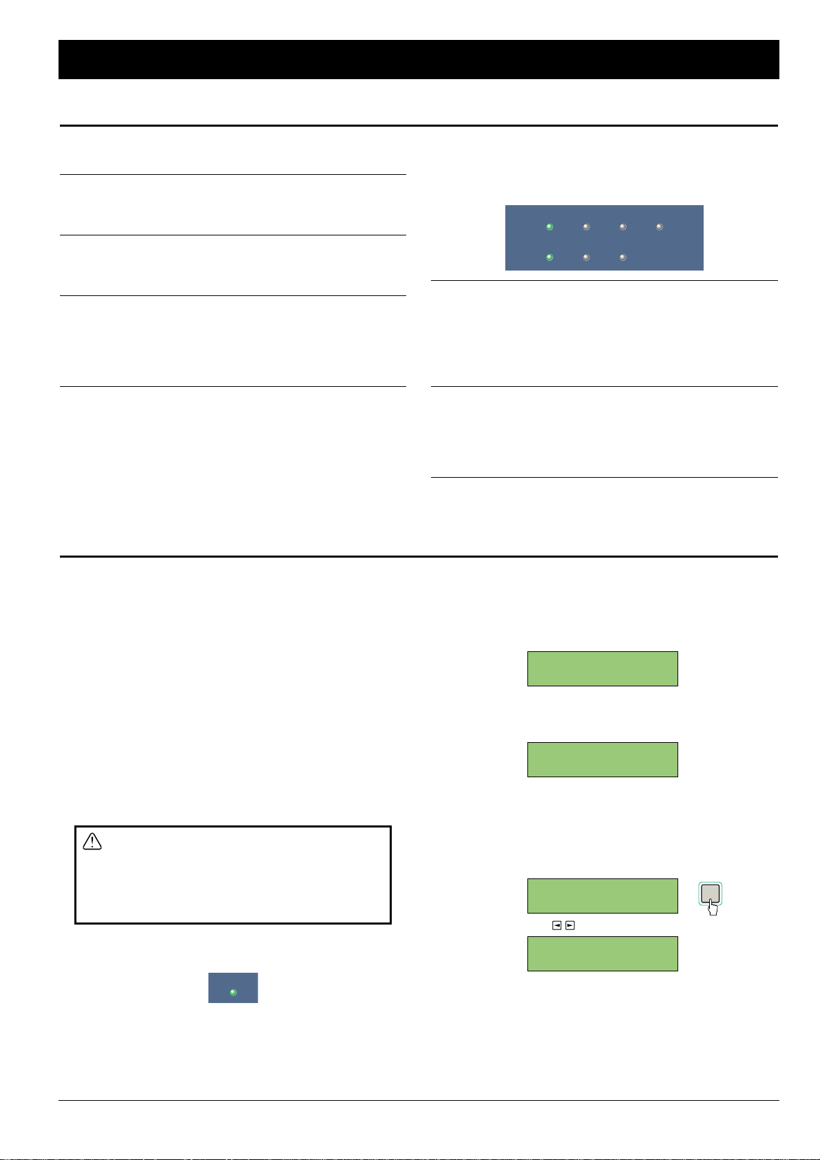
■ List of Reference Clock Signals: The following signals can
be used as the reference clock signal.
■■ INT: selects the internal clock signal of the FS-96. The
frequency of the signal can be selected from the following 6
options — 32, 44 (44.1), 48, 64, 88 (88.2), 96 kHz.
■■ WORD: selects the external Word Clock signal supplied to the
WORD IN connector. The frequency of the signal varies with
the setting of the external device.
■■ INPUT: selects the Word Clock signal extracted from the
input audio signals. If the input audio signals consist of
multiple groups, you can select which group is used
(AES/EBU = INPUT 1/2 – 23/24 ch, ADAT & TDIF (including
Bi-Direction mode) = GROUP A – C).
NOTE: The output audio signals will be synchronized to the
reference clock signal with phase-level accuracy.
■ Indication of Reference Clock and Sample Rate: The
selection of the reference clock signal and the sample rate of the
output audio will be displayed by the Reference Clock and
Sample Rate indicators on the front panel.
■■ Reference Clock Indicators: The selection of the reference
clock signal is displayed by the Reference Clock indicators —
INT (internal clock signal), EXT (external Word Clock signal),
and INPUT (input audio signal). If no signal is present or no
synchronization is achieved for the input signal, the indicator
will flash.
■■ Sample Rate Indicators: Each of the indicators will illuminate
when the frequency of the output signal is within a range of ±1
% of the labeled frequencies. If the signal is 64 kHz, both the
32 kHz and 44.1 kHz indicators are lit. Also, if the signal is
88.2 kHz, both the 44.1 kHz and 48 kHz indicators are lit.
96kHz 48kHz 44.1kHz 32kHz
INT EXT INPUT
October 2000 19
Setup Mode
Selecting Reference Clock (Continued)
Configuring Sample Rate Converter
According to the accuracy of the devices, there are slight
fluctuations or jitters in the sample rates of digital audio signals.
The FS-96 is equipped with an accurate clock generation circuit
and the input audio signals can be converted to accurate signals
by passing through the sample rate converter.
■ Using Sample Rate Converter: Activation of the sample rate
converter should be determined by the settings of input format
and reference clock signal. If the audio signals are to be
converted to a different sample rate, you must turn on the
sample rate converter to obtain proper audio outputs. If the
output signals is to be synchronized to the input signals (or the
external Word Clock signal which is synchronized to the input
signals), the sample rate converters are not necessary. However,
we recommend to activate the sample rate converters all the
time.
If the sample rate of the input audio is different
from the frequency of the reference clock
signal, please be sure to activate the sample
rate converter. If the sample rate converter is
turned off, annoying noise may appear on the
audio signals.
NOTE: Status of the sample rate converter is displayed on the
SRC indicator on the front panel.
1. Press the SETUP key to place the FS-96 in Setup mode
and select the SAMPLE RATE CONVERT screen by
pressing the upper & lower Arrow keys.
The current status of the sample rate converter is displayed
on the screen.
2. Press the ENTER key to activate the parameter.
The current status is displayed with parentheses.
3. Select the activation of sample rate converters with the
right & left Arrow keys. Then, press the ENTER key to
store the setting.
The setting is stored into the current setting memory and is
reflected onto the actual setting.
(USE TO SELECT ON / OFF)
NOTE: When “BDIR” (Bi-Direction mode) is selected as the input
format, the sample rate converter will be automatically turned off.
SAMPLE RATE 0
CONVERT: ON
SAMPLE RATE 0
CONVERT:<ON >
SAMPLE RATE 0
CONVERT:<OFF>
SAMPLE RATE 0
CONVERT: OFF
SRC
ENTER
Page 20
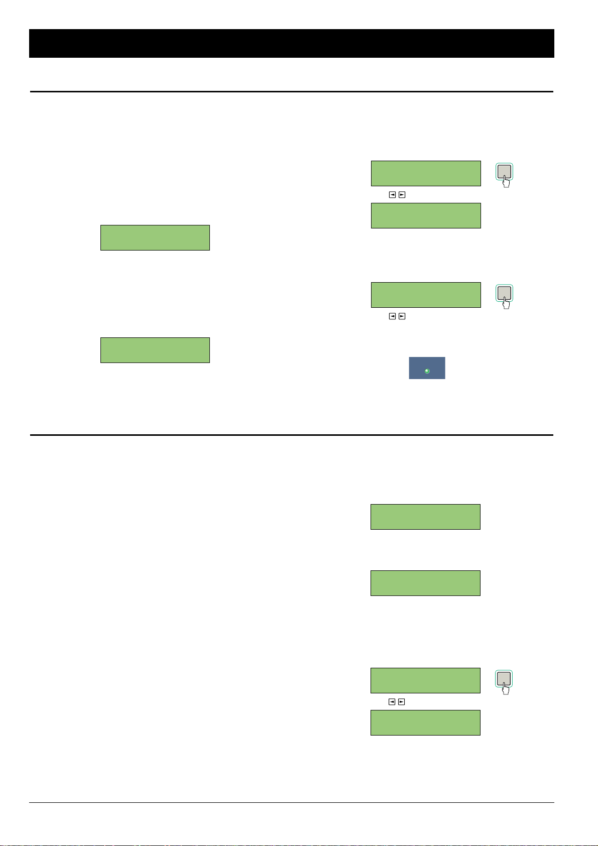
The bit resolution (the number of quantization bits) of the output
audio signals can be changed from three options — 16 bits, 20
bits, and 24 bits.
NOTE: To change the bit resolution, you must turn on the
sample rate converter.
1. Press the SETUP key to place the FS-96 in Setup mode
and select the OUTPUT RES. screen by pressing the
upper & lower Arrow keys.
The current bit resolution is displayed on the screen.
The FS-96 automatically detects the bit resolution of the
input signals. Normally, the bit resolution of the input signals
is selected in this screen.
2. Press the ENTER key to activate the parameter.
The current selection is displayed with parentheses and the
other choices are displayed on the screen.
3. Select the desired bit resolution with the right & left
Arrow keys. Then, press the ENTER key to store the
selection.
The selection is stored into the current setting memory and
is reflected onto the actual setting.
(USE TO SELECT BIT RESOLUTION)
4. If the sample rate converter is turned off, select “YES”
in the following screen and press the ENTER key to
activate the sample rate converter.
(USE TO SELECT YES / NO)
NOTE: Status of the sample rate converter is displayed on the
SRC indicator on the front panel.
SRC
ENTER
ENABLE SRC? 0
<YES> NO
OUTPUT RES.: 0
24BITS
OUTPUT RES.: 0
20 <24BITS> 16
OUTPUT RES.: 0
24 <16BITS> 20
OUTPUT RES.: 0
16BITS
20 February 2001
Setup Mode
Changing Bit Resolution
Activating Dither Function
When the bit resolution is decreased, the dither function can be
activated for the audio data.
■ About Dither Function: When the bit resolution is changed in
a decreasing direction (e.g., 24 → 20 / 16, 20 → 16), distortion
may appear on the audio signals since the lower bits of each
sample are cut (LSB, 21st bit and later bits or 17th bit and later
bits). In this case, activating the dither function causes the output
audio signals to become more natural, by adding a slight noise
to the audio signals before changing bit resolution.
NOTES:
• Although the dither function can decrease distortion, the signal
to noise ratio may fall slightly by activating the dither function.
Also, activating the dither function may add noise to the audio
signals. Thus, activation of the dither function should be
determined by listening to the audio signals.
• The dither function is not applied if the bit resolution is changed
in an increasing direction (e.g., 16 → 20 / 24, 20 → 24), since
the vacant bits will be filled with zeroes.
1. Press the SETUP key to place the FS-96 in Setup mode
and select the DITHER screen by pressing the upper &
lower Arrow keys.
The current status for the dither function is displayed on the
screen.
2. Press the ENTER key to activate the selection.
The current status is displayed with parentheses.
3. Select the activation of dither function with the right &
left Arrow keys and press the ENTER key to store the
selection.
The selection is stored into the current setting memory and
is reflected onto the actual setting.
(USE TO SELECT ON / OFF)
DITHER: 0
ON
DITHER: 0
< ON >
DITHER: 0
< OFF >
DITHER: 0
OFF
ENTER
ENTER
Page 21
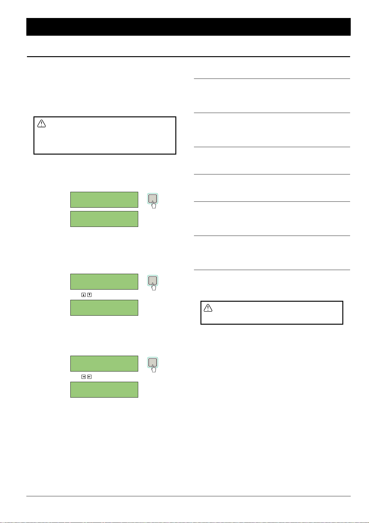
The status data are contained in each of the digital audio formats
to indicate the status of the audio signals. The FS-96 can edit
the status data for each format.
NOTE: The settings of the status data editing screens are
normally set to “THRU”. The status data of the input signals are
not changed and are output to the external devices as they are.
The status data should be set properly
according to the actual signal status. If the
status data do not match the actual signal
status, the signal may not be reproduced
properly on the destination devices.
1. Press the SETUP key to place the FS-96 in Setup mode
and select the OUTPUT STATUS screen by pressing the
upper & lower Arrow keys.
The status data setting screen is displayed on the LCD.
2. Select the desired item with the upper & lower Arrow
keys and press the ENTER key to activate the
parameter.
The current selection is displayed with parentheses and the
other choices are displayed on the screen.
(USE TO SELECT ITEM)
3. Select the desired value with the right & left Arrow keys
and press the ENTER key to store the selection.
The selection is stored into the current setting memory and
is reflected onto the actual setting.
(USE TO CHANGE PARAMETER)
4. Repeat the steps 2 and 3, until all of the desired
parameters are set.
5. After all settings are finished, press the CANCEL key to
return to the OUTPUT STATUS screen. Or, press the
SETUP key to return to the initial screen.
■ List of Status Data: The following status data can be edited
on the FS-96.
■■ AES/EBU EMPH. (emphasis): indicates the emphasis status
of the AES/EBU signals. The following options are available:
THRU (same as input), 50/15 (50/15 µs), CCITT, OFF, NO
INDICATE (no indication).
■■ AES/EBU FREQ. (frequency): indicates the sample rate of
the AES/EBU signals. The following options are available:
THRU (same as input), 32k, 44k, 48k, 88k, 96k, NO INDICATE
(no indication), AUTO (interlocked to reference clock).
■■ SDIF EMPH. (emphasis): indicates the emphasis status of
the SDIF-2 signals. The following options are available: THRU
(same as input), ON, OFF.
■■ TDIF EMPH. (emphasis): indicates the emphasis status of
the TDIF-1 signals. The following options are available: THRU
(same as input), ON, OFF.
■■ TDIF BIT RES. (bit resolution): indicates the bit resolution of
the TDIF-1 signals. The following options are available: THRU
(same as input), 24BITS, 20BITS, 16BITS, AUTO (interlocked
to output bit resolution).
■■ TDIF FREQ. (frequency): indicates the sample rate of the
TDIF-1 signals. The following options are available: THRU
(same as input), 32k, 44k, 48k, OTHER, AUTO (interlocked to
reference clock).
NOTE: The FS-96 cannot edit any status data which are not
mentioned above. Such status data will not be changed from
those of input signals.
The status data are used only to indicate the
signal status. Note that the actual signal will
not be changed by editing the status data.
AES/EBU EMPH.: 0
CCITT
AES/EBU EMPH.: 0
015 <CCITT> OFF
AES/EBU EMPH.: 0
NID <THRU > 5015
AES/EBU EMPH.: 0
THRU
AES/EBU EMPH.: 0
THRU
OUTPUT STATUS: 0
February 2001 21
Setup Mode
Editing Status Data
ENTER
ENTER
ENTER
Page 22
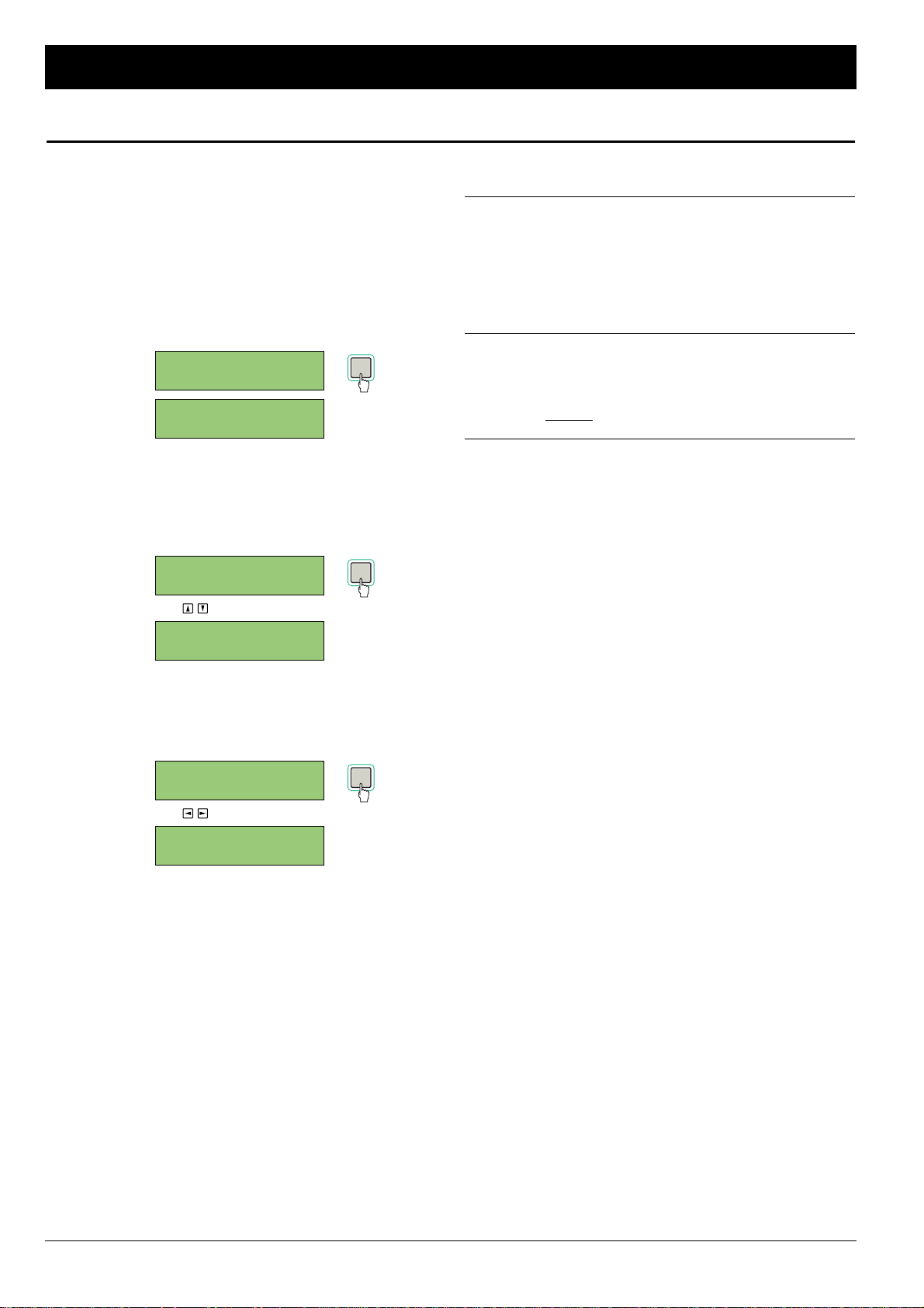
A digital audio signal consists of a set of audio data and a
synchronization signal. The synchronization signal is used to
perform audio data sampling with proper timing. If there is a gap
between these two signals, the proper audio signals may not be
reproduced. The FS-96 can adjust the synchronization timing of
these two signals.
1. Press the SETUP key to place the FS-96 in Setup mode
and select the SYNC TIMING screen by pressing the
upper & lower Arrow keys.
The SYNC TIMING screen appears on the LCD.
2. Select the desired item with the upper & lower Arrow
keys and press the ENTER key to activate the
parameter.
The current selection is displayed with parentheses and the
other choices are displayed on the screen.
(USE TO SELECT ITEM)
3. Select the desired value with the right & left Arrow keys
and press the ENTER key to store the selection.
The selection is stored into the current setting memory and
is reflected onto the actual setting.
(USE TO CHANGE PARAMETER)
4. Repeat the steps 2 and 3 until the desired parameters
are set.
5. When the parameters are set to the desired values,
press the CANCEL key to return to the SYNC TIMING
screen. Or, press the SETUP key to return to the initial
screen.
■ Parameters in SYNC TIMING Screen: The following
parameters can be set in the SYNC TIMING screen.
■■ INPUT DELAY: used to adjust the delay for the clock signal
extracted from the input audio signals, within a range of ±2
units (1 unit = 5 ns). This will change the timing of audio data
sampling relatively to the clock signal. Individual settings are
possible for the three input groups for the TDIF-1 and ADAT
interfaces, while a single setting is available for the SDIF
interface.
■■ TDIF OUTPHASE (Output Signal Phase): used to adjust
the output timing of the TDIF-1 signals, relatively to the Word
Clock signal. This will adjust the signal phases of the LR clock
and audio data. Adjustment is possible in a range of ±2 clocks
(1 clock = ).
NOTE: The above settings are normally set to “±0”. If there is no
problem in audio signal transmissions, the setting need not be
changed.
1
Fs x 256
INPUT DELAY B: 0
-2UNIT
INPUT DELAY B: 0
+2 < -2UNIT > -1
INPUT DELAY B: 0
-1 < 0UNIT > +1
INPUT DELAY B: 0
0UNIT
INPUT DELAY A: 0
0UNIT
SYNC TIMING: 0
22 February 2001
Setup Mode
Adjusting Sync Timing
ENTER
ENTER
ENTER
Page 23
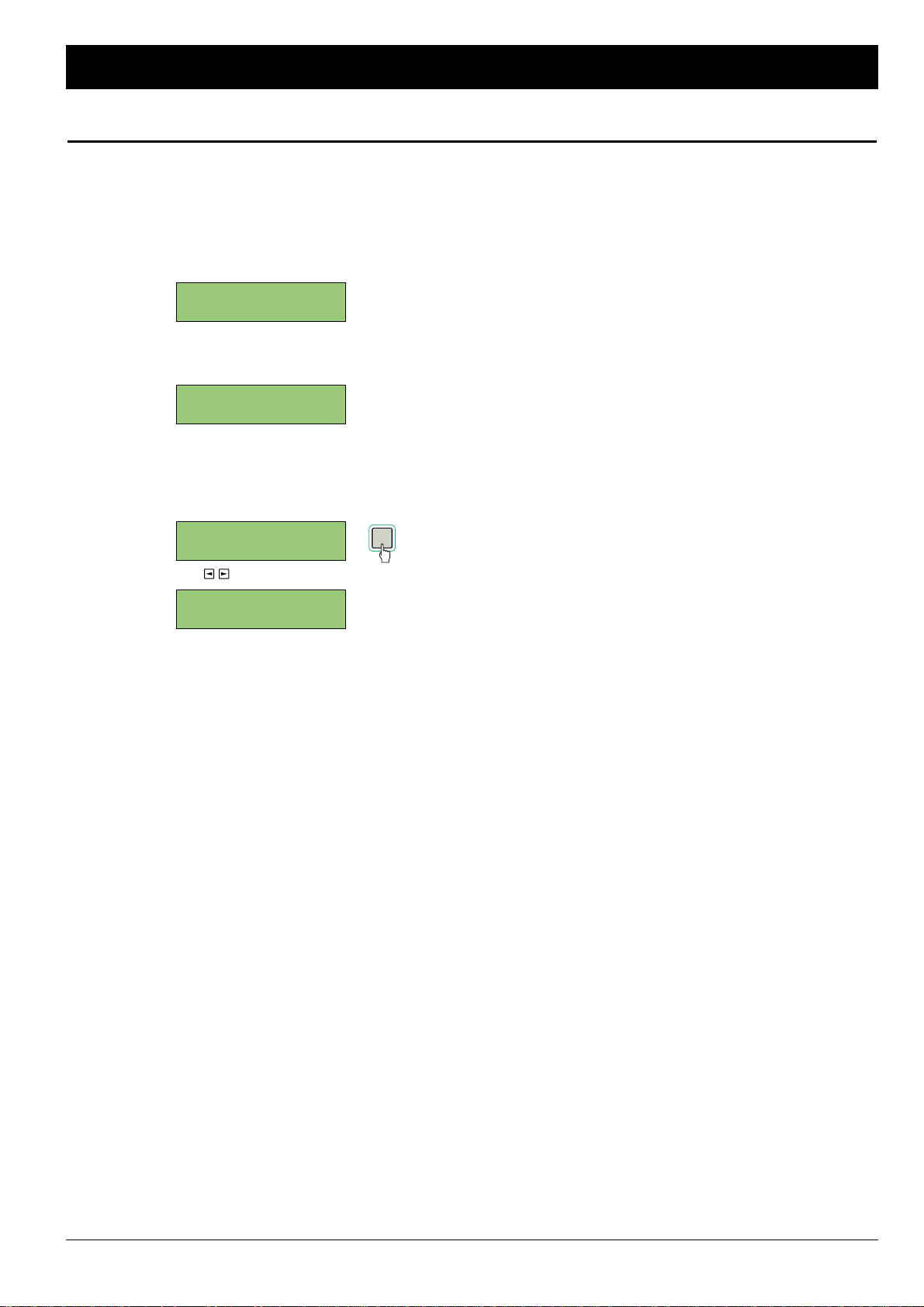
The contrast of the LCD can be changed via the operation on
the LCD. This parameter is separate from the setting memories
and only a single setting is stored in the system memory.
1. Press the SETUP key to place the FS-96 in Setup mode
and select the LCD CONTRAST screen by pressing the
upper & lower Arrow keys.
2. Press the ENTER key to select the screen.
The current contrast setting is displayed as a graph.
3. Adjust the screen contrast with the right & left Arrow
keys and press the ENTER key to store the setting.
Adjust the LCD contrast so that the screen can be easily
read under operating conditions.
(USE TO ADJUST CONTRAST)
LCD CONTRAST:
LCD CONTRAST:
<- **------ +>
LCD CONTRAST:
<- *****--- +>
LCD CONTRAST:
February 2001 23
Setup Mode
Adjusting LCD Contrast
ENTER
Page 24
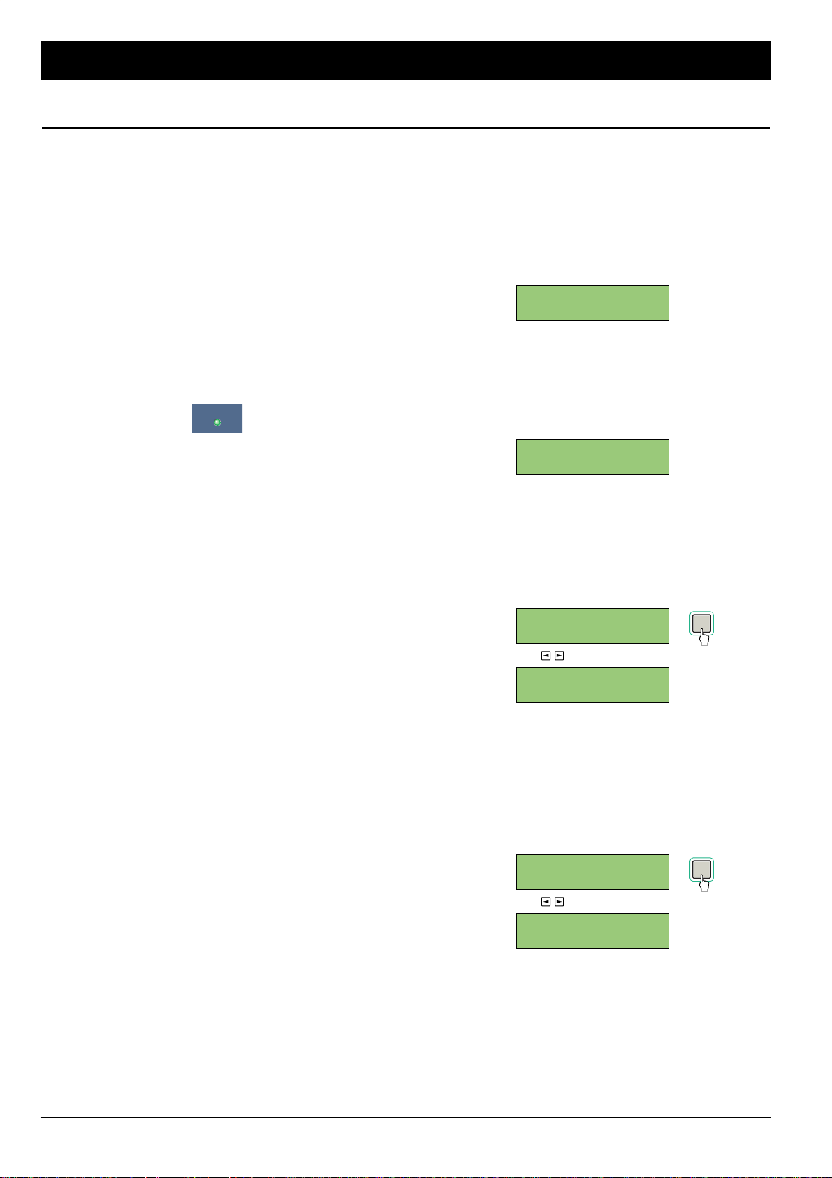
■ About Signal Routing: In addition to the capabilities of signal
format and sample rate conversions, the FS-96 can be used as a
digital signal router. By using this function, connections of input
and output channels can be changed internally, without
changing any physical connections. It is possible to change the
alignment of the channels or to supply the audio of a single input
channel to multiple output channels.
NOTES:
• To leave Routing mode, press the ROUTING key so that the
key’s indicator goes off. If you are to move the FS-96 from
Routing mode to Setup mode, you must leave Routing mode
first before pressing the SETUP key.
• The current routing memory number is displayed in upper right
corner of the routing configuration screen.
• When the signal routing is turned off (set to 1 : 1), the 1 : 1
indicator illuminates on the front panel.
■ Using Routing Memories: The FS-96 utilizes two preset
memories consisting of the setting memories and routing
memories. The routing memories are used only for storing the
signal routing configurations, while the setting memories are
used to store all operation settings excluding the signal routing
configurations. Note that the changes made in Routing mode will
be stored into the routing memory which is currently selected.
Before you make any changes to the settings, confirm that the
desired preset memory number is displayed on the initial screen.
NOTE: In addition to the 10 preset memories, a special routing
memory (“1 : 1”) is provided for deactivating the signal routing.
This preset memory is automatically used when the FS-96 is
placed into Bi-Direction mode.
■ Configuring Signal Routing: The configuration of the signal
routing is made by assigning the input channels to the output
channels. When configuring the signal routing, follow the
instructions below.
1. Select the desired routing memory number.
The routing settings will be stored into the current routing
memory. Be sure to select the proper routing memory
number.
2. Press the ROUTING key to place the FS-96 into Routing
mode and confirm that the routing configuration screen
appears on the LCD.
The current routing settings are displayed on the LCD. The
upper line shows the output channels and the lower line
shows the input channels assigned to the output channels.
3. Select an output channel with the right & left Arrow keys
and press the ENTER key to activate the selection.
The selection of an output channel is displayed by straight
bars (“||”) surrounding the selected channel number.
When the ENTER key is pressed, the selection moves to the
input channel and the selection of the input channel is
displayed with parentheses (“<>”).
(USE TO SELECT OUTPUT CHANNEL)
4. Use the right & left Arrow keys to select the input
channel to be assigned to the output channel. Then,
press the ENTER key to store the connection between
the input and output channels.
When the ENTER key is pressed, the signal routing setting is
stored into the current memory and the actual signal routing
will be changed.
The selection moves to the output channel.
(USE TO SELECT INPUT CHANNEL)
5. Repeat the steps 3 and 4 for the desired channels.
6. After the signal routing settings are finished, press the
ROUTING key to return to the initial screen.
O:|09|10 11 12 1
I: 01 10 11 12
O: 09 10 11 12 1
I:<01>10 11 12
O: 09 10 11 12 1
I:<09>10 11 12
O:|09|10 11 12 1
I: 09 10 11 12
←
OUTPUT CH
←
INPUT CH
O:|01|02 03 04 1
I: 01 02 03 04
SETTING MEM.: 0
ROUTING MEM.: 1
24 February 2001
Routing Mode
Configuring Signal Routing
1:1
ENTER
ENTER
Page 25
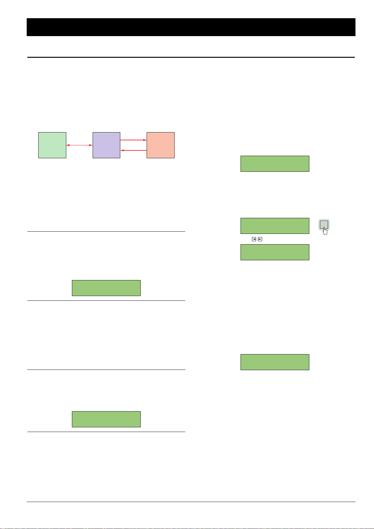
■ About Bi-Directional Conversion: The TDIF-1 interface can
handle 8 channels of both inputs and outputs with a single cable
and is used on many digital recorders for its ease of connection.
However, when it becomes necessary to connect to a device
which does not support TDIF-1interface, a special branch cable
is needed. In order to solve this problem, the FS-96 is equipped
with a “Bi-Direction mode” which enables simultaneous signal
format conversions in both directions between the TDIF-1 and
AES/EBU interfaces.
By using this function, conversion of TDIF-1 inputs to AES/EBU
outputs and conversion of AES/EBU inputs to TDIF-1 outputs
are performed simultaneously.
NOTE: The bi-directional conversion is possible only between
the TDIF-1 and AES/EBU interfaces.
■ Limitations in Bi-Direction mode: When in Bi-Direction
mode, the operations of the FS-96 are limited as follows:
■■ Limitations on Signal Routing: No signal routing is possible
in Bi-Direction mode. The signal routing will be deactivated
and a special routing memory is used, indicating “1 : 1” as the
routing memory number on the initial screen. If the ROUTING
key is pressed, or if the routing memory is selected, the
following screen appears for about 2 seconds.
■■ Limitations on Reference Clock: The reference clock for
the output audio signals should be set to the TDIF-1 input
signals or the external Word Clock signal that is synchronized
to the TDIF-1 input signals. Although the reference clock can
be set to the other signals, the audio signals will be output
with no synchronization.
When “BDIR” is selected in the INPUT FORMAT screen, the
reference clock will be changed automatically to the groups A
of the TDIF-1 input signals.
■■ Limitations on Sample Rate Converters: The status of the
sample rate converters cannot be changed. Even if the sample
rate converter is activated, it will be turned off automatically by
entering into Bi-Direction mode. If the sample rate converter is
turned on, the following screen appears for about 2 seconds.
■ Activating Bi-Direction mode: To use the FS-96 in Bi-
Direction mode, follow the instructions below.
1. Confirm that the connections are properly made to the
TDIF-1 and AES/EBU interfaces.
2. Turn on the power to the FS-96 and select the desired
setting memory.
3. Place the FS-96 into Setup mode by pressing the
SETUP key and select the INPUT FORMAT screen.
Then, press the ENTER key to activate the current input
format selection.
4. Use the right & left Arrow keys and select “BDIR
(Bi-
DIRection)
”. Then, press the ENTER key to store the
selection.
The selection is stored into the current setting memory and
the FS-96 is now placed in Bi-Direction mode.
(USE TO SELECT INPUT FORMAT)
When in Bi-Direction mode, the FS-96 operates as follows:
• Both the AES/EBU and TDIF-1 indicators are lit. The
indicators will flash if the signal is not present or if the
synchronization cannot be achieved for the input signal.
• The reference clock for the output signals is changed to
the group A of the TDIF-1 input and the INPUT indicator of
the Reference Clock indicators is lit. If no signal is present,
or if the synchronization cannot be achieved for the input
signal, the indicator will flash.
• No routing memory is used and the signal routing is turned
off. The 1 : 1 indicator illuminates on the front panel. The
display of the initial screen will be changed as follows:
• The sample rate converters are turned off and the SRC
indicator goes off on the front panel.
SETTING MEM.: 0
ROUTING MEM.:1:1
INPUT FORMAT: 0
BDIR
INPUT FORMAT: 0
TDIF <BDIR> AES
INPUT FORMAT: 0
BDIR < AES> ADAT
BI-DIR MODE
SRC NOT AVAIL.
BI-DIR MODE
1:1 ROUTING ONLY
February 2001 25
Bi-Direction Mode
Using Bi-Direction Mode
TDIF-1
IN/OUT
FS-96RECORDER CONSOLE
OUT IN
AES/EBU
IN OUT
ENTER
Page 26
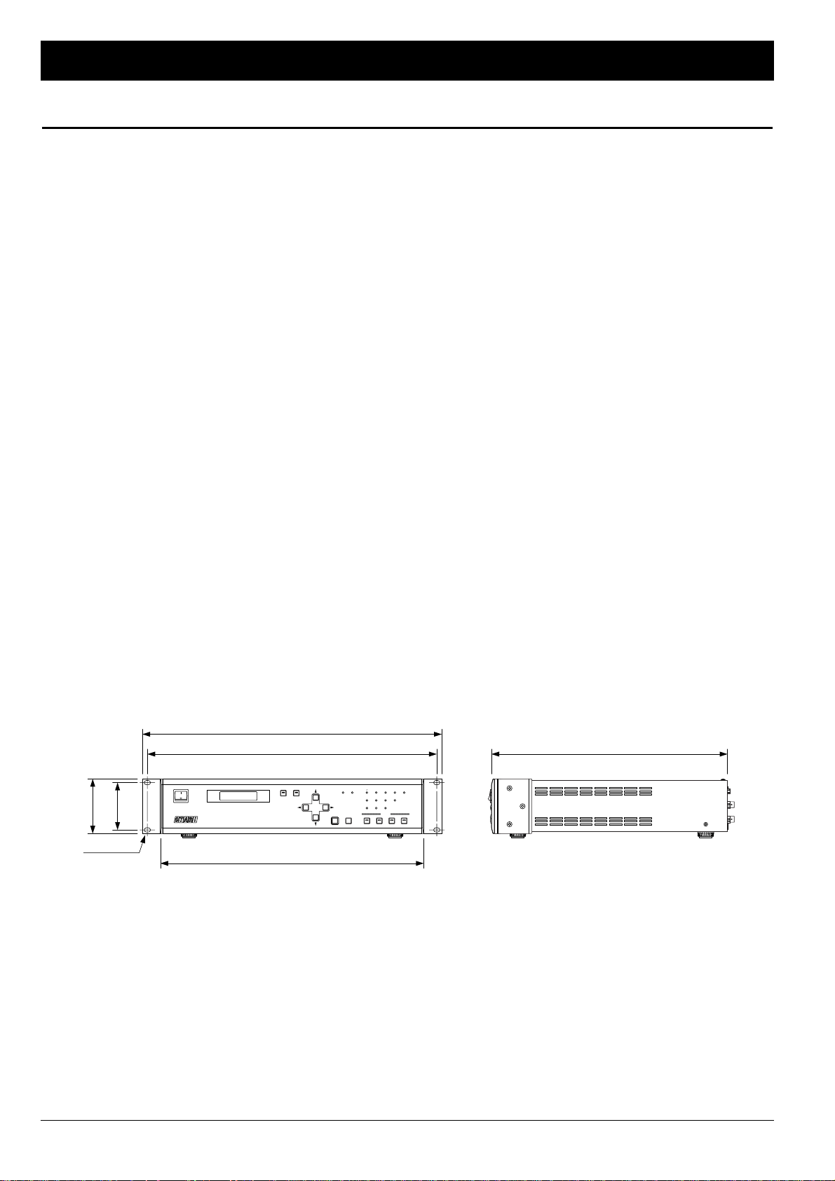
ADAT Format Inputs and Outputs:
Signal Format: Alesis Fiberoptic Multichannel
Connector: Input: EIAJ fiber optic jack x 3
Output: EIAJ fiber optic jack x 3
AES/EBU (AES3) Format Inputs and Outputs:
Signal Format: EIAJ CP1201, IEC60958, AES3
Impedance: 110 Ω (both input & output)
Connector: Input: D-sub 25-pin (female) x 3
Output: D-sub 25-pin (female) x 3
SDIF-2 Format Inputs and Outputs:
Signal Format: SDIF-II
Impedance: 110 Ω (both input & output)
Connector: Audio Input: D-sub 50-pin (male) x 1
Audio Output: D-sub 50-pin (female) x 1
Word Clock Input & Output:
BNC type (75 Ω, TTL) x 2
TDIF-1 Format Inputs and Outputs:
Signal Format: TDIF-1
Impedance: Input: Min. 1 kΩ
Output: 56 Ω ±20 %
Connector: D-sub 25-pin (female) x 3
External Synchronization Input and Output:
Signal Type: Word clock
Format: Sync to rising edge of square wave
Electrical Characteristics: TTL level
Impedance: 75 Ω (both input & output)
Connector: BNC type x 2 (input x 1, output x 1)
Digital Audio Format:
ADAT, AES/EBU, SDIF-2, TDIF-1
An option slot for the expansion module
is provided on the rear panel.
Number of Channels:
24, with signal routing function
Sample Rate: 28 kHz – 108 kHz variable
Number of Quantization Bits:
16 / 20 / 24 bits, switchable
The bit resolution of the input signals is
detected automatically.
Signal Delay: 2–3 samples
Liquid Crystal Display:
16 characters x 2 lines,
with backlight mechanism
Dimensions (W x H x D, without projections):
482 x 88 (2U) x 380 mm
Weight: 6.0 kg
Power Supply: 100 – 240 VAC
(single phase, 50 / 60 Hz)
Power Consumption:
Maximum 50 W
Operation Environment:
Temperature: 5 – 40 °C
Humidity: 20 – 80 %
26 February 2001
Specifications
FS-96 Specifications
SETUP ROUTING
SRC AES EBU
96kHz 48kHz 44.1kHz 32kHz
INT EXT INPUT
ADAT SDIF-2 TDIF-1 OPTION
PRESET
ENTER CANCEL
1:1
1234
POWER
FORMAT & SAMPLE RATE CONVERTER
FS--96
76.2
88
466 380
482
424
7 x 10 Hole
Specifications are subject to change without notice or obligation.
Page 27

Page 28

Otari, Inc. 4-33-3 Kokuryo-cho, Chofu-shi, Tokyo 182-0022 Japan • Phone : +81/424-81-8626 • Fax : +81/424-81-8633
Otari Corporation 8236 Remmet Avenue, Canoga Park, California 91304 U.S.A. • Phone : +1/818-598-1200 • Fax : +1/818-594-7208
Otari Europe GmbH Rudolf-Diesel-Strasse 12, D-40670 Meerbusch, Germany • Phone : +49/2159-50861 • Fax : +49/2159-1778
Otari Singapore Pte., Ltd. 701 Sims Drive #02-02 LHK Building, Singapore 387383 • Phone : +65/846-1553 • Fax : +65/846-7875
©
2000, 2001 Otari, Inc. Printed in Japan, February 2001
 Loading...