

Osburn OB01111 User Manual
OWNER`S MANUAL
STOVE BUILDER INTERNATIONAL INC
1100
(OB01111 model)
US ENVIRONMENTAL PROTECTION AGENCY PHASE II CERTIFIED WOODSTOVE
250, de Copenhague,
Saint-Augustin-de-Desmaures
(Quebec), Canada G3A 2H3
After-sale service: 418-908-8002
E-mail: tech@sbi-international.com
.
Verified and tested following
ULC S627 and UL 1482 Standards by
an accredited laboratory
This manual is available for free download on the manufacturer’s web site. It is a
copyrighted document. Re-sale is strictly prohibited. The manufacturer may update this
manual from time to time and cannot be responsible for problems, injuries, or damages
arising out of the use of information contained in any manual obtained from unauthorized
sources.
READ AND KEEP THIS MANUAL FOR REFERENCE
45127A
Printed in Canada 12-06-2015
www.osburn-mfg.com

INTRODUCTION
REGISTER YOU WARRANTY ONLINE
SBI INC., one of the most important wood stove and fireplace manufacturers in Canada,
congratulates you on your purchase and wishes to help you get maximum satisfaction from your
wood stove. In the pages that follow, we will give you advice on wood heating and controlled
combustion as well as technical specifications regarding installation, operation and maintenance
of the model you have chosen.
The instructions pertaining to the installation of your wood stove comply with ULC-S627 and UL1482 standards.
We recommend that our wood burning hearth products be installed and serviced by professionals
who are certified in the United States by NFI (National Fireplace Institute®) or in Canada by WETT
(Wood Energy Technical Training) or in Quebec by APC (Association des Professionnels du
Chauffage).
Read this entire manual before you install and use your new stove. If this stove is not
properly installed, a house fire may result. To reduce the risk of fire, follow the installation
instructions. Failure to follow instructions may result in property damage, bodily injury, or
even death.
Consult your municipal building department or fire officials about restrictions and
installations requirements in your area and the need to obtain a permit.
Keep this instructions manual for future references.
CAUTIONS:
• T
HE INFORMATION GIVEN ON THE CERTIFICATION LABEL AFFIXED TO THE APPLIANCE ALWAYS OVERRIDES
THE INFORMATION PUBLISHED, IN ANY OTHER MEDIA (OWNER’S MANUAL, CATALOGUES, FLYERS,
MAGAZINES AND/OR WEB SITES
•
HOT WHILE IN OPERATION. KEEP CHILDREN, CLOTHING AND FURNITURE AWAY. CONTACT MAY CAUSE
SKIN BURNS
•
DO NOT USE CHEMICALS OR FLUIDS TO IGNITE THE FIRE
•
DO NOT LEAVE THE STOVE UNATTENDED WHEN THE DOOR IS SLIGHTLY OPENED
•
DO NOT BURN WASTES, FLAMMABLE FLUID SUCH AS GASOLINE, NAPHTHA OR MOTOR OIL
•
DO NOT CONNECT TO ANY AIR DISTRIBUTION DUCT OR SYSTEM
•
ALWAYS CLOSE THE DOOR AFTER THE IGNITION
.
).
.
.
.
.
.
To receive full warranty coverage, you will need to show evidence of the
date you purchased your stove. Keep your sales invoice. We also
recommend that you register your warranty online at
http://www.osburn-mfg.com/en/service-support/warranty-registration
Registering your warranty online will help us track rapidly the information
we need on your stove.
2

TABLE OF CONTENTS
INTRODUCTION ............................................................................................................................................ 2
OVERALL STOVE DIMENSIONS .................................................................................................... 4
INSTALLATION REQUIREMENTS ............................................................................................................ 5
R
ESIDENTIAL INSTALLATION INSTRUCTIONS
M
ANUFACTURED (MOBILE) HOME INSTALLATIONS – ADDITIONAL REQUIREMENTS
......................................................................................... 5
............................ 6
INSTALLATION ............................................................................................................................................. 7
G
ENERAL INSTALLATION
D
OOR OVERLAY INSTALLATION
C
LEARANCES TO COMBUSTIBLES AND FLOOR PROTECTOR
....................................................................................................................... 7
............................................................................................................. 8
................................................................ 9
CHIMNEY SYSTEM..................................................................................................................................... 16
D
EFINITIONS
C
OMPONENTS
F
ACTORY BUILT CHIMNEY SYSTEM
R
ESIDENTIAL CLOSE CLEARANCES CHIMNEY SYSTEM
G
ENERAL INSTALLATION REQUIREMENTS
C
HIMNEY CONNECTOR
C
HIMNEY SYSTEMS
E
XTERIOR CHIMNEY
D
RAFT
T
YPICAL TYPES OF CHIMNEY SYSTEMS
........................................................................................................................................ 16
..................................................................................................................................... 16
.................................................................................................... 16
...................................................................... 17
.......................................................................................... 17
........................................................................................................................ 17
............................................................................................................................. 19
............................................................................................................................ 20
.................................................................................................................................................. 20
............................................................................................. 21
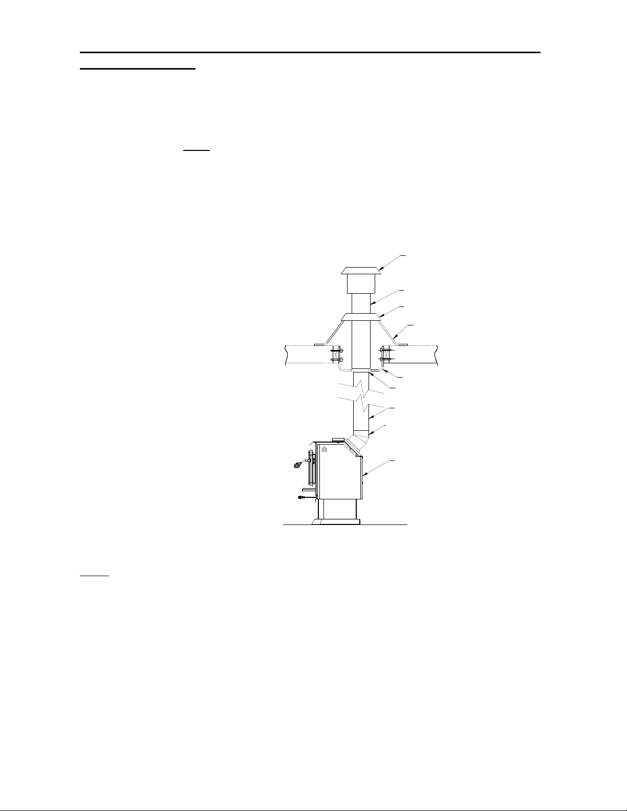
FIGURE 1.9 CONNECTION TO A FACTORY BUILT CHIMNEY (EXTERIOR
SHOWN)OPERATION ................................................................................................................................ 22
OPERATION ................................................................................................................................................. 23
S
AFETY INFORMATION
F
UEL
.................................................................................................................................................... 24
S
IMPLE WOOD MOISTURE TEST
N
OTES ABOUT FIRST FIRING
L
IGHTING A FIRE
M
AINTAINING THE FIRE
(O
PTIONAL) BLOWER INSTALLATION AND OPERATION
......................................................................................................................... 23
......................................................................................................... 25
.............................................................................................................. 25
................................................................................................................................. 25
....................................................................................................................... 27
....................................................................... 28
MAINTENANCE ........................................................................................................................................... 29
C
ARE AND CLEANING
G
LASS CLEANING
A
SH REMOVAL USING ASH DRAWER
C
HIMNEY CLEANING
B
AFFLE INSTALLATION AND BRICK NOTES
B
RICK LAYOUT
S
ECONDARY AIR TUBE REPLACEMENT
.................................................................................................................................... 33
.......................................................................................................................... 29
................................................................................................................................ 29
.................................................................................................. 29
............................................................................................................................ 31
......................................................................................... 32
.............................................................................................. 33
TROUBLESHOOTING ................................................................................................................................ 34
SPECIFICATIONS ....................................................................................................................................... 35
OSBURN LIMITED LIFETIME WARRANTY .......................................................................................... 36
3
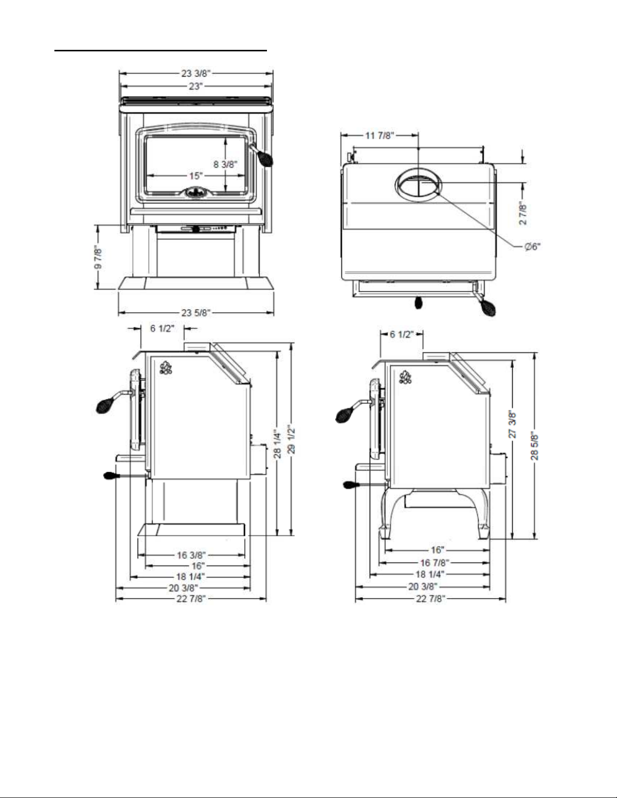
OVERALL STOVE DIMENSIONS
Figure 1
4

INSTALLATION REQUIREMENTS
In Canada the CSA B365 Installation Code for Solid Fuel Burning Appliances and Equipment
and the CSA C22.1 Canadian National Electrical Code are to be followed in the absence of
local code requirements. In the USA the ANSI NFPA 70 National Electrical Code and NFPA
211 Standard for Chimneys, Fireplaces, Vents and Solid Fuel-Burning Appliances are to be
followed in the absence of local code requirements.
In addition to the national installation codes, local building and/or fire officials (or other
authorities having jurisdiction) should be contacted to determine what restrictions and
installation requirements might locally apply.
When installed and operated as described in these instructions, the 1100 is intended to be
used as the following:
as a residential freestanding stove with vertical or horizontal connector.
in a mobile home*.
in an alcove.
as a Hearth mount stove for masonry or zero clearance fireplaces.
The 1100 is not intended for installation in a sleeping room.
* The 1100 wood stove is ‘mobile home approved’ only with the pedestal option and with
optional OA10500 and AC02090.
RESIDENTIAL INSTALLATION INSTRUCTIONS
Choose a location for the unit which meets the minimum clearances to combustibles (see
Figure 1.3). For other than masonry chimneys determine if the factory built chimney will pass
between the ceiling joists; if not, choose a new location so that it will, while still maintaining
the minimum clearances.
Mark the location for the floor protection (if required) as noted in Figure 1.3.
Note: If outside air for combustion is to be used it should be provided for at this time. This
requires that the Osburn Fresh air intake kit Wood (#OA10500) be installed (refer to the
installation instructions which are provided in the fresh air intake kit). Install the unit.
5
MANUFACTURED (MOBILE) HOME INSTALLATIONS – ADDITIONAL
FACTORY BUILT CHIMNEY
OSBURN 1100
REQUIREMENTS
1. The stove must be bolted to the floor (secure the unit by prying out the two plastic
plugs in the pedestal, and installing the two 3/8" x 3-1/2" (9.8mm x 88.9mm) lag
bolts through the holes provided).
2. The unit
3. Clearance from the top of stove to an unprotected ceiling should be a minimum of
52” (1321mm).
4. The stove must be used connected to the chimney with listed double wall connector
of 6" (152 mm) diameter.
5. The chimney system must be a minimum of 12' (3658 mm) in height from the
hearth pad to the top of the chimney assembly.
Note: For manufactured home installations in the USA, the stove must be grounded to the
frame of the home using a # 8 ground wire with approved terminations and star lock
washers.
C
AUTION
:
T
HE STRUCTURAL INTEGRITY OF THE MANUFACTURED HOME FLOOR, WALL, CEILING / ROOF
M
UST BE MAINTAINED
must
be provided with outside combustion air.
TYPICAL MOBILE
HOME INSTALLATION
Figure1.1 Necessary installation components.
.
RAINCAP
STORM COLLAR
DOUBLE WALL 45° ELBOW
C
AUTION
:
DO N
OT INSTALL IN A SLEEPING ROOM
.
6

INSTALLATION
When installed and operated as described in these instructions, the Osburn 1100 wood stove
is suitable for use as a freestanding wood stove in residential installations. The E.P.A
certified Osburn wood stove is not intended for installation in a bedroom.
In Canada, the CSA B365 Installation Code for Solid Fuel Burning Appliances and Equipment
and the CSA C22.1 Canadian National Electrical Code are to be followed in the absence of
local code requirements. In the USA, the ANSI NFPA 70 National Electrical Code and NFPA
211 Standard for Chimneys, Fireplaces, Vents and Solid Fuel-Burning Appliances are to be
followed in the absence of local code requirements.
In addition to the national installation and/or local building codes, fire officials (or other
authorities having jurisdiction) should be contacted to determine what restrictions and
installation requirements might apply locally.
GENERAL INSTALLATION
CAUTION:
•
MIXING OF APPLIANCE OR FLUE SYSTEM COMPONENTS FROM DIFFERENT SOURCES OR MODIFYING THE
DIMENSIONAL SPECIFICATION OF COMPONENTS MAY RESULT IN HAZARDOUS CONDITIONS. WHERE SUCH
ACTION IS CONSIDERED, THE MANUFACTURER SHOULD BE CONSULTED IN THE FIRST INSTANCE
• D
O NOT CONNECT THIS UNIT TO ANY AIR DISTRIBUTION SYSTEM
•
CRACKED AND BROKEN COMPONENTS,
INSTALLATION UNSAFE
• A
SOURCE OF FRESH AIR INTO THE ROOM OR SPACE HEATED SHALL BE PROVIDED WHEN REQUIRED
•
INSTALL A SMOKE DETECTOR IN THE ROOM WHERE THE STOVE IS LOCATED
.
e.g.
GLASS PANELS OR CERAMIC TILES, MAY RENDER THIS
.
.
.
•
C
ONNECT THE STOVE ONLY TO A LINED MASONRY CHIMNEY CONFORMING TO NATIONAL AND LOCAL
BUILDING CODES FOR USE WITH SOLID FUEL, OR TO A LISTED FACTORY BUILT CHIMNEY SUITABLE FOR
USE WITH SOLID FUEL
.
This heating unit must serve as a supplementary heat source. An alternative heat source
should be available in the home if needed. The manufacturer cannot be responsible for
additional heating costs associated with the use of an alternative heat source.
It is highly recommended that the user buys this product from a retailer who can provide
installation and maintenance advices.
7
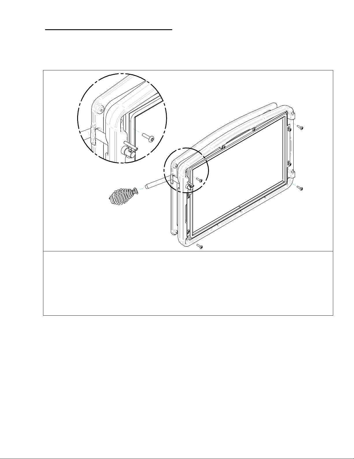
DOOR OVERLAY INSTALLATION
In order to complete the assembly of your freestanding Osburn 1100 wood stove, you need to
install the door overlay. See Figure 1.2 below for installation instructions :
1- Position the overlay on the door frame and fix it in place from behind using the 4
screws.
Note: It is not necessary to remove the glass or any other component to install the overlay.
Figure 1.2 Door overlay installation
8
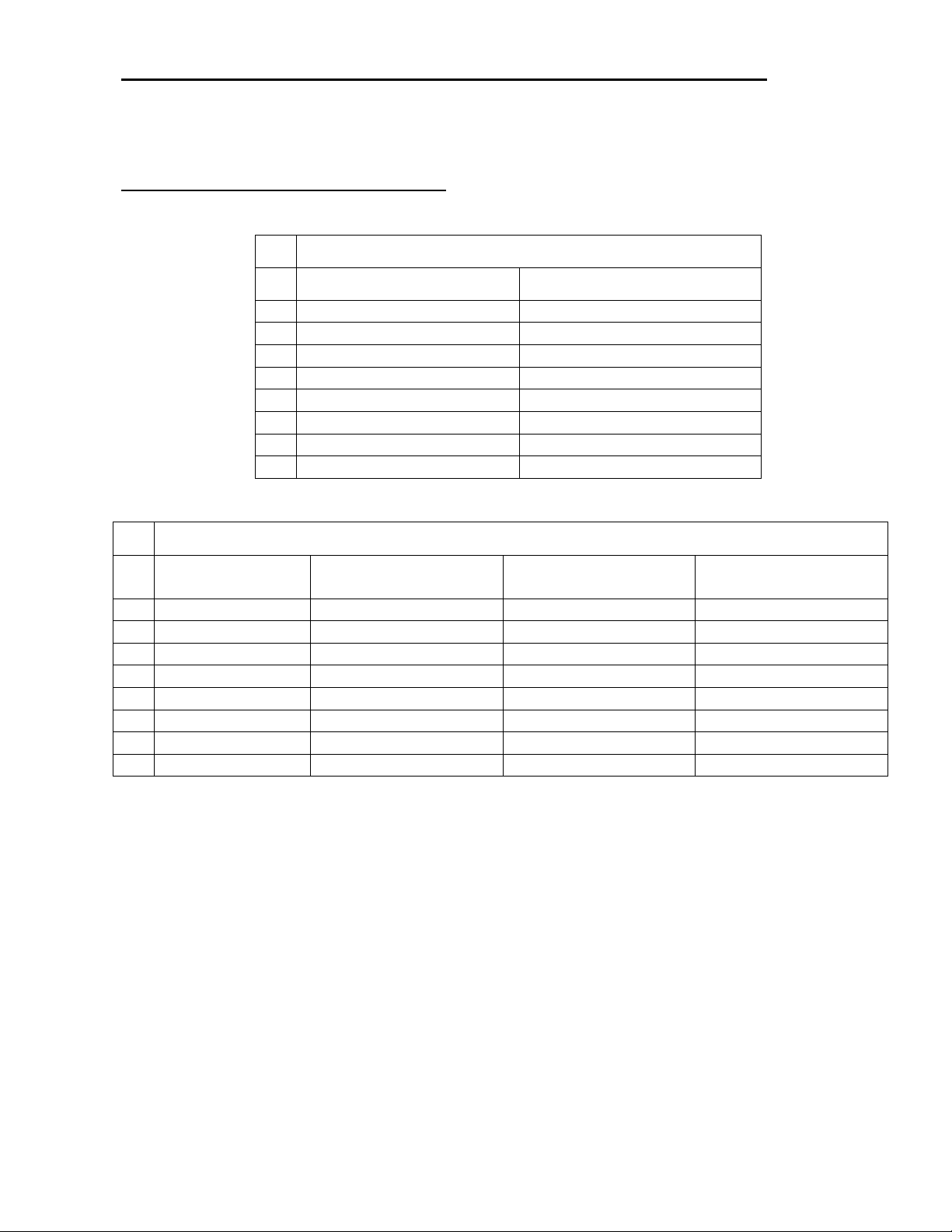
CLEARANCES TO COMBUSTIBLES AND FLOOR PROTECTOR
A
B
C
D
E
F
K
L
ALCOVE
MOBILE HOME
A
B
C
D
E
F
K
L
To install your appliance correctly, it is extremely important to respect all clearances to any
combustibles as indicated on your stove’s certification label.
Clearances to combustible materials
(see figure 1.3 to match each letter to a clearance)
CLEARANCES (SINGLE WALL PIPE)
CANADA USA
20" (508 mm) 20" (508 mm)
16" (406 mm) 16" (406 mm)
14" (356 mm) 14" (356 mm)
21" (533 mm) 21" (533 mm)
25" (635 mm) 25" (635 mm)
19" (482 mm) 19" (482 mm)
48" (1220 mm) 48" (1220 mm)
84" (213 cm) 84" (213 cm)
CANADA USA
CLEARANCES (DOUBLE WALL PIPE)
CANADA / USA
CANADA / USA
12" (305 mm) 12" (305 mm) 13" (330 mm) 12" (305 mm)
17" (432 mm) 17" (432 mm) 13" (330 mm) 17" (432 mm)
6" (152 mm) 6" (152 mm) - 6" (152 mm)
13" (330 mm) 13" (330 mm) 14" (356 mm) 13" (330 mm)
26" (660 mm) 26" (660 mm) 22" (559 mm) 26" (660 mm)
11" (279 mm) 11" (279 mm) - 11" (279 mm)
48" (1220 mm) 48" (1220 mm) 48" (1220 mm) 48" (1220 mm)
84" (213 cm) 84" (213 cm) 84" (213 cm) 84" (213 cm)
9
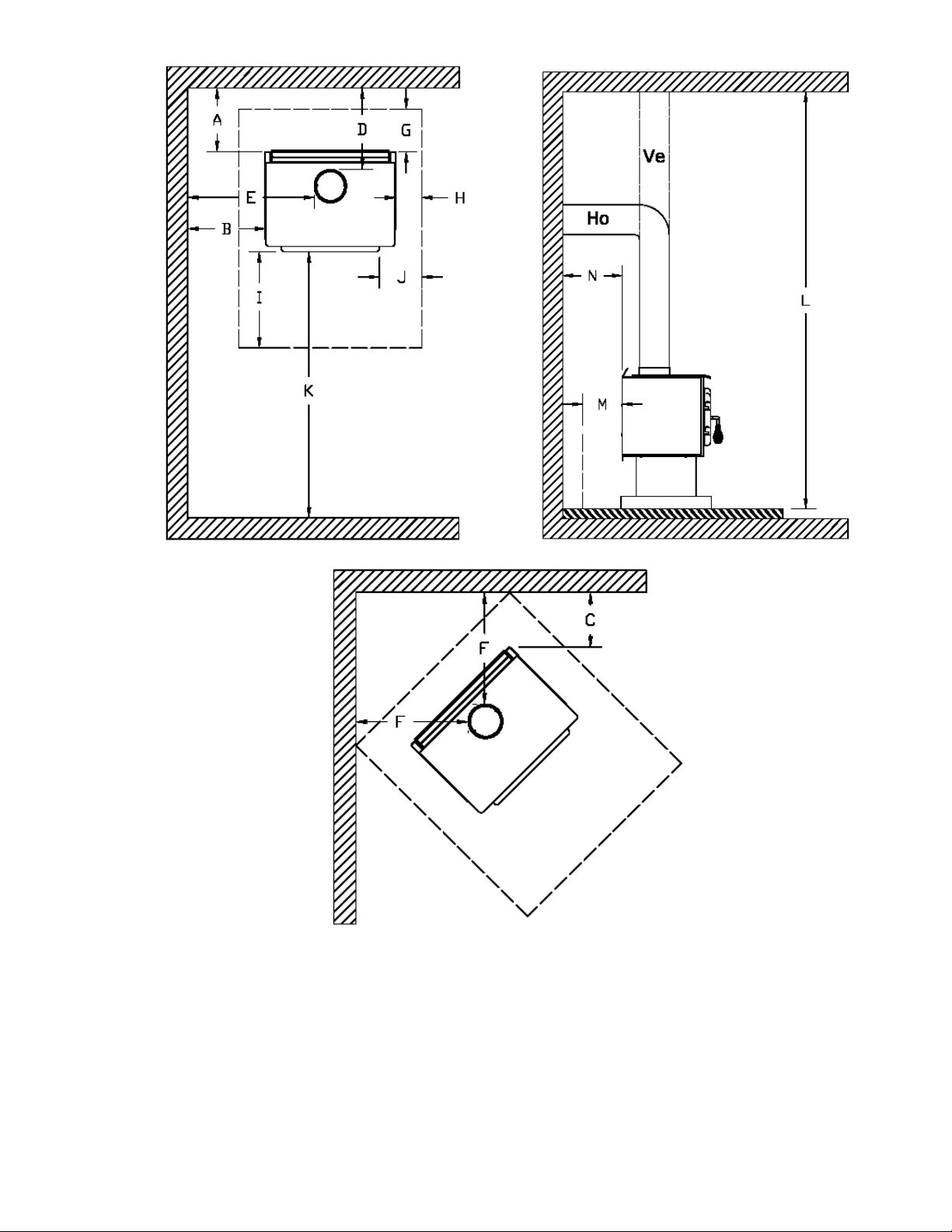
FIGURE 1.3 Clearances to combustible materials and floor protection
10
Floor protector
G
H
I
J
M
N
If the stove is to be installed on top of a combustible floor, it must be guarded by a non
combustible material as shown on figure 1.3 (see the dotted line area).
FLOOR PROTECTOR*
8’’ (203 mm) – Note 1 N/A (Canada only)
*Steel with a minimum thickness of 0.015’’ (0.38 mm) or ceramic tiles sealed together with
grout. No protection is required if the unit is installed on a non-combustible floor (ex:
concrete).
Note 1 : The floor protection at the back of the stove is limited to the stove’s required
clearance if such clearance is smaller than 8 inches (203 mm).
Note 2 : Only required under the horizontal section of the connector. Must exceed each
side of the connector by at least 2 inches (51 mm).
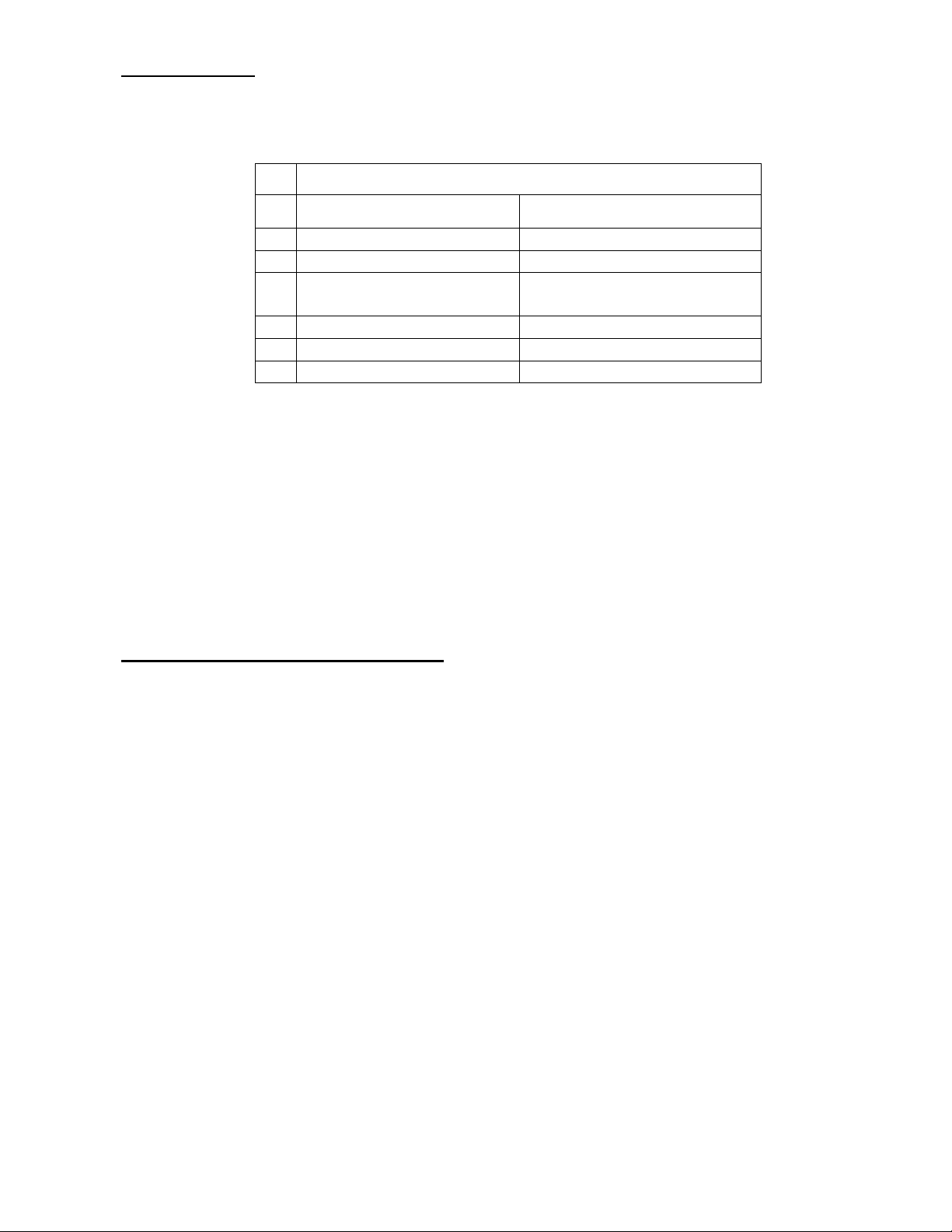
Reduced clearances using shielding
You may decrease the clearances by installing heat radiation shields between the walls or the
ceiling and the stove. These heat radiation shields must be installed permanently, and can
include sheet metal, a rigid non-combustible sheet or a masonry wall.
Clearances of not less than 1" (25 mm) and not more than 3" (76 mm) between the bottom of
the shield and the floor and not less than 3" (76 mm) between the top of the shield and the
ceiling must be respected to allow vertical air circulation behind the shield. The shield must
extend 20" (500 mm) above the stove top and 18" (450mm) to each side of the stove (see
graphic 1).
Following the installation of such a heat radiation shield, the clearances mentioned on the
stove certification plate may be reduced as stated in the following table.
CANADA USA
8’’ (203 mm) N/A (Canada only)
18’’ (457 mm)
From door opening
N/A (USA only) 8’’ (203 mm)
8’’ (203 mm) N/A (Canada only)
N/A (USA only) Note 2
16’’ (406 mm)
From door opening
11
 Loading...