

Page 1
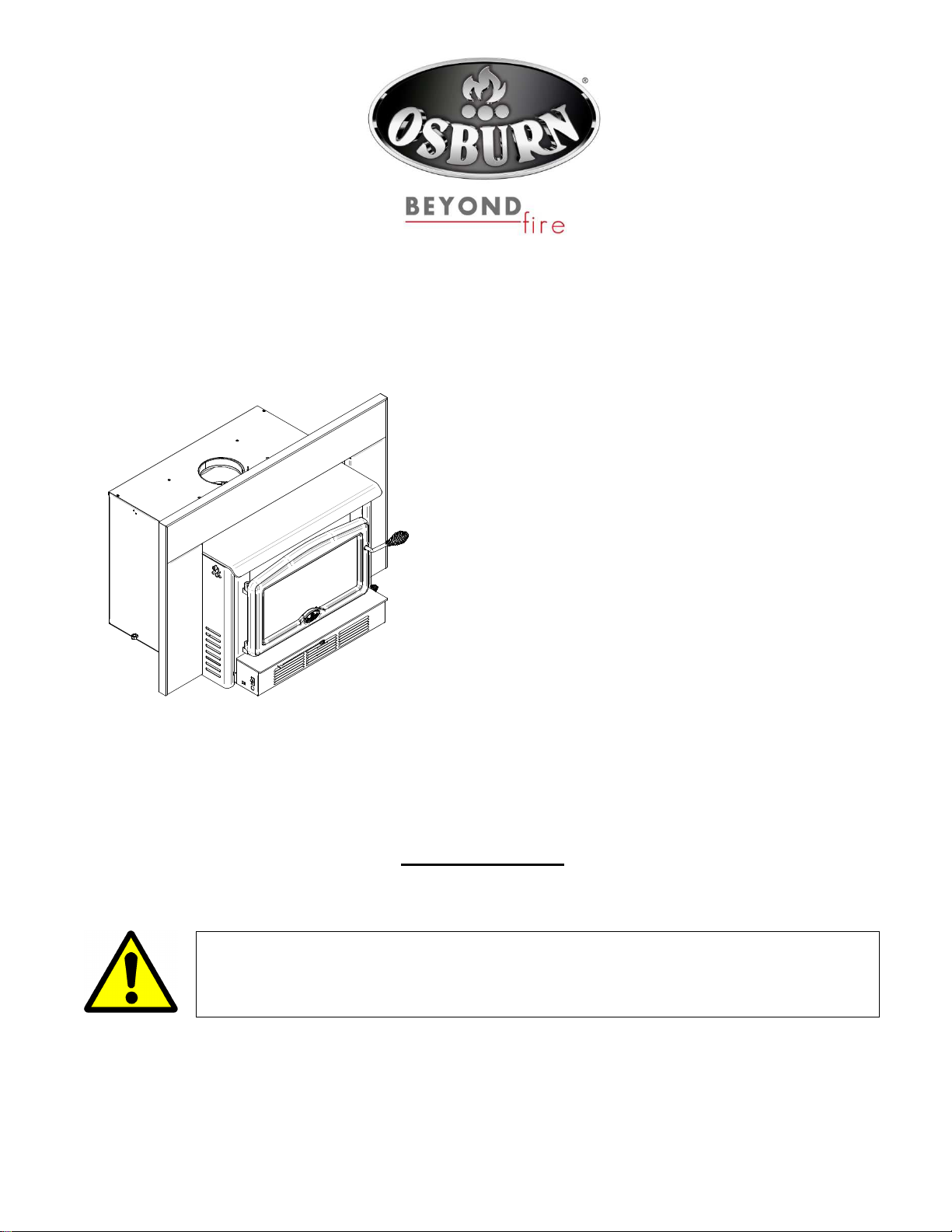
OWNER`S MANUAL
2400 INSERT
(OB02401 model)
US ENVIRONMENTAL PROTECTION
AGENCY PHASE II CERTIFIED
WOOD INSERT
Verified and tested following
ULC S628 and UL 1482 Standards
by an accredited laboratory
Manufactured by: STOVE BUILDER INTERNATIONAL INC..
250, rue de Copenhague, Saint-Augustin-de-Desmaures (Quebec) G3A 2H3
After-sale service: 418-908-8002 E-mail: [email protected]
www.osburn-mfg.com
This manual is available for free download on the manufacturer’s web site. It is a copyrighted
document. Re-sale is strictly prohibited. The manufacturer may update this manual from time
to time and cannot be responsible for problems, injuries, or damages arising out of the use of
information contained in any manual obtained from unauthorized sources.
READ AND KEEP THIS MANUAL FOR REFERENCE
45111A
Printed in Canada 12-06-2015
Page 2

INTRODUCTION
SBI INC., one of the most important wood stove and fireplace manufacturers in Canada,
congratulates you on your purchase and wishes to help you get maximum satisfaction from your
wood stove. In the pages that follow, we will give you advice on wood heating and controlled
combustion as well as technical specifications regarding installation, operation and maintenance
of the model you have chosen.
The instructions pertaining to the installation of your wood stove comply with ULC-S628 and UL1482 standards.
We recommend that our wood burning hearth products be installed and serviced by
professionals who are certified in the United States by NFI (National Fireplace Institute®) or in
Canada by WETT (Wood Energy Technical Training) or in Quebec by APC (Association des
Professionnels du Chauffage).
Read this entire manual before you install and use your new stove. If this stove is not
properly installed, a house fire may result. To reduce the risk of fire, follow the
installation instructions. Failure to follow instructions may result in property damage,
bodily injury, or even death.
Consult your municipal building department or fire officials about restrictions and
installations requirements in your area and the need to obtain a permit.
Keep this instructions manual for future references.
CAUTIONS:
• T
HE INFORMATION GIVEN ON THE CERTIFICATION LABEL AFFIXED TO THE APPLIANCE ALWAYS
OVERRIDES THE INFORMATION PUBLISHED, IN ANY OTHER MEDIA (OWNER’S MANUAL, CATALOGUES,
FLYERS, MAGAZINES AND/OR WEB SITES
•
HOT WHILE IN OPERATION. KEEP CHILDREN, CLOTHING AND FURNITURE AWAY. CONTACT MAY CAUSE
SKIN BURNS
•
DO NOT USE CHEMICALS OR FLUIDS TO IGNITE THE FIRE
•
DO NOT LEAVE THE STOVE UNATTENDED WHEN THE DOOR IS SLIGHTLY OPENED
•
DO NOT BURN WASTES, FLAMMABLE FLUID SUCH AS GASOLINE, NAPHTHA OR MOTOR OIL
•
DO NOT CONNECT TO ANY AIR DISTRIBUTION DUCT OR SYSTEM
•
ALWAYS CLOSE THE DOOR AFTER THE IGNITION
.
).
.
.
.
.
.
This heating unit must serve as a supplementary heat source. An alternative heat source should be available in the home if
needed. The manufacturer cannot be responsible for additional heating costs associated with the use of an alternative heat
source.
It is highly recommended that the user buys this product from a retailer who can provide installation and maintenance advices.
2
Page 3

TABLE OF CONTENTS
REGISTER YOU WARRANTY ONLINE
1.0 PRE-INSTALLATION REQUIREMENTS ................................................................................... 4
1.1
M
1.2
1.3
ASONRY FIREPLACE REQUIREMENTS
V
ENTING REQUIREMENTS
D
OOR OVERLAY INSTALLATION
................................................................................................................ 5
...................................................................................................... 6
............................................................................................ 4
2.0 INSTALLATION .............................................................................................................................. 7
2.1 S
AFETY INFORMATION
2.2 I
NSTALLATION INSTRUCTIONS
2.3 C
OMPLIANCE OF THE MASONRY FIREPLACE
2.4 T
HE MASONRY FIREPLACE'S DRAFT CONTROL SYSTEM
2.5 C
OMPLIANCE OF A COMBUSTIBLE TOP SHELF
2.6 P
OSITIONING THE UNIT
2.7 M
INIMUM MASONRY OPENING, CLEARANCES TO COMBUSTIBLES, AND FLOOR PROTECTOR
2.8 C
ONNECTOR INSTALLATION
2.8.1 C
2.8.1.1 I
2.8.1.2 I
2.9
HIMNEY LINER INSTALLATION
F THE CHIMNEY LINER DOES ALIGN WITH THE INSERT’S FLUE OUTLET, YOU HAVE TWO OPTIONS
F THE CHIMNEY LINER DOES NOT ALIGN WITH THE INSERT’S FLUE OUTLET
F
ACEPLATE INSTALLATION
.......................................................................................................................... 7
............................................................................................................... 8
.......................................................................................... 8
.......................................................................... 9
........................................................................................ 9
........................................................................................................................ 10
................. 14
................................................................................................................ 16
....................................................................................................... 17
: 17
: ................................. 18
........................................................................................................... 18
3.0 OPERATION ................................................................................................................................... 24
3.1
S
3.2
3.2.1 S
3.3
3.4
3.5
3.6
AFETY INFORMATION
F
UEL
............................................................................................................................................. 25
IMPLE WOOD MOISTURE TEST
N
OTES ABOUT FIRST FIRING
L
IGHTING A FIRE
M
AINTAINING THE FIRE
B
LOWER OPERATION
.................................................................................................................. 24
...................................................................................................... 26
.......................................................................................................... 26
........................................................................................................................... 26
................................................................................................................. 27
..................................................................................................................... 28
4.0 MAINTENANCE ............................................................................................................................ 29
4.1
C
4.2
4.3
4.4
4.5
ARE AND CLEANING
A
SH REMOVAL
C
HIMNEY CLEANING
C
REOSOTE – FORMATION AND NEED FOR REMOVAL
S
ECONDARY AIR TUBE REPLACEMENT (SEE FIGURE
.............................................................................................................................. 29
.................................................................................................................... 29
..................................................................................................................... 30
...................................................................... 30
4.5) ............................................................... 31
5.0 TROUBLESHOOTING .................................................................................................................. 32
6.0 SPECIFICATIONS ......................................................................................................................... 33
OSBURN LIMITED LIFETIME WARRANTY .................................................................................... 34
To receive full warranty coverage, you will need to show evidence of the
date you purchased your insert. Keep your sales invoice. We also
recommend that you register your warranty online at
http://www.osburn-mfg.com/en/service-support/warranty-registration
Registering your warranty online will help us track rapidly the information
we need on your insert.
3
Page 4

1.0 PRE-INSTALLATION REQUIREMENTS
1.1 Masonry fireplace requirements
The masonry fireplace must meet the minimum code requirements, or NFPA 211 or the equivalent
for a safe installation. Contact your local Building Inspector for requirements in your area. An
inspection of the fireplace should include the following:
1. CONDITION OF THE FIREPLACE AND CHIMNEY:
Examine the masonry fireplace and chimney prior to installation, to determine that they are free
from cracks, loose mortar, creosote deposits, blockage, or other signs of deterioration. If
evidence of deterioration is noted, the fireplace or chimney should be upgraded prior to
installation.
2. CHIMNEY CAPS:
Mesh type chimney caps must have provision for regular cleaning, or the mesh should be
removed to eliminate the potential of plugging.
3. LINER:
The chimney must have an acceptable 6" (152 mm) stainless steel chimney liner installed.
NOTE: The 2400 Insert is not approved for use with a positive flue connector into a masonry
flue.
4. ADJACENT COMBUSTIBLES:
The fireplace should be inspected to make sure that there is adequate clearance to
combustibles, both exposed combustibles to the top, side, and front as well as concealed
combustibles, in the chimney and mantel area. Your local inspector should have information on
whether older fireplaces are of adequate construction.
5. OPENING SIZE:
Refer to “Minimum masonry opening” (Section 2.7) for suitable size fireplace openings.
NOTE:
A METAL TAG IS PROVIDED AND IS TO BE FASTENED TO THE BACK WALL OF THE
FIREPLACE, IF THE FIREPLACE HAS BEEN MODIFIED TO ACCOMMODATE THE
INSERT.
4
Page 5

1.2 Venting requirements
The flue is a critical component to a satisfactory installation. Your insert will attain its best
performance if installed with a flue that generates its own draft. The minimum venting requirement
will be the installation of a flue connector from the insert into the first tile of the chimney. If you are
using a masonry chimney, it is important that it be built in compliance with the specifications of the
National Building Code or other applicable standard having jurisdiction. It must be lined with fire clay
bricks, metal or clay tiles sealed together with fire cement (round flues are the most efficient). Ideally,
the interior diameter of the masonry chimney should be identical to the insert smoke exhaust. You
may also run a stainless steel liner inside the masonry chimney. A continuous 6" (152mm) stainless
steel liner from the top of the chimney to the insert’s smoke exhaust is the optimum system and will
provide the best performance, as well as compensate for poor draft situations caused by large
cross-sectional chimneys. The insert will not work without a positive seal in the chimney.
Chimneys constructed outside of the home, on an exterior wall, should be avoided if possible,
especially in colder climates. Outside chimneys may not draw as well and may downdraft due to the
difficulty in heating them up to operating temperature. Cooler chimneys will result in increased
creosoting, less draft, and poorer performance. Draft is proportional to overall chimney height as
well as to stack temperature. Draft can be increased by increasing chimney height, and by reducing
heat loss from the chimney through an insulated liner.
Ensure that all joints in the flue systems are tightly sealed, since any leaks will result in reduced
performance as well as a possible safety hazard. Using a fire screen at the extremity of the chimney
requires regular inspection in order to insure that it is not obstructed thus blocking the draught, and it
should be cleaned when necessary.
Do not connect this unit to a chimney flue serving another appliance.
This heating unit must serve as a supplementary heat source. An alternate heat source should be
available in the home if needed. The manufacturer cannot be responsible for additional heating
costs associated with the use of an alternative heat source.
It is recommended that the user buys this product from a retailer who can provide installation and
maintenance advices.
5
Page 6
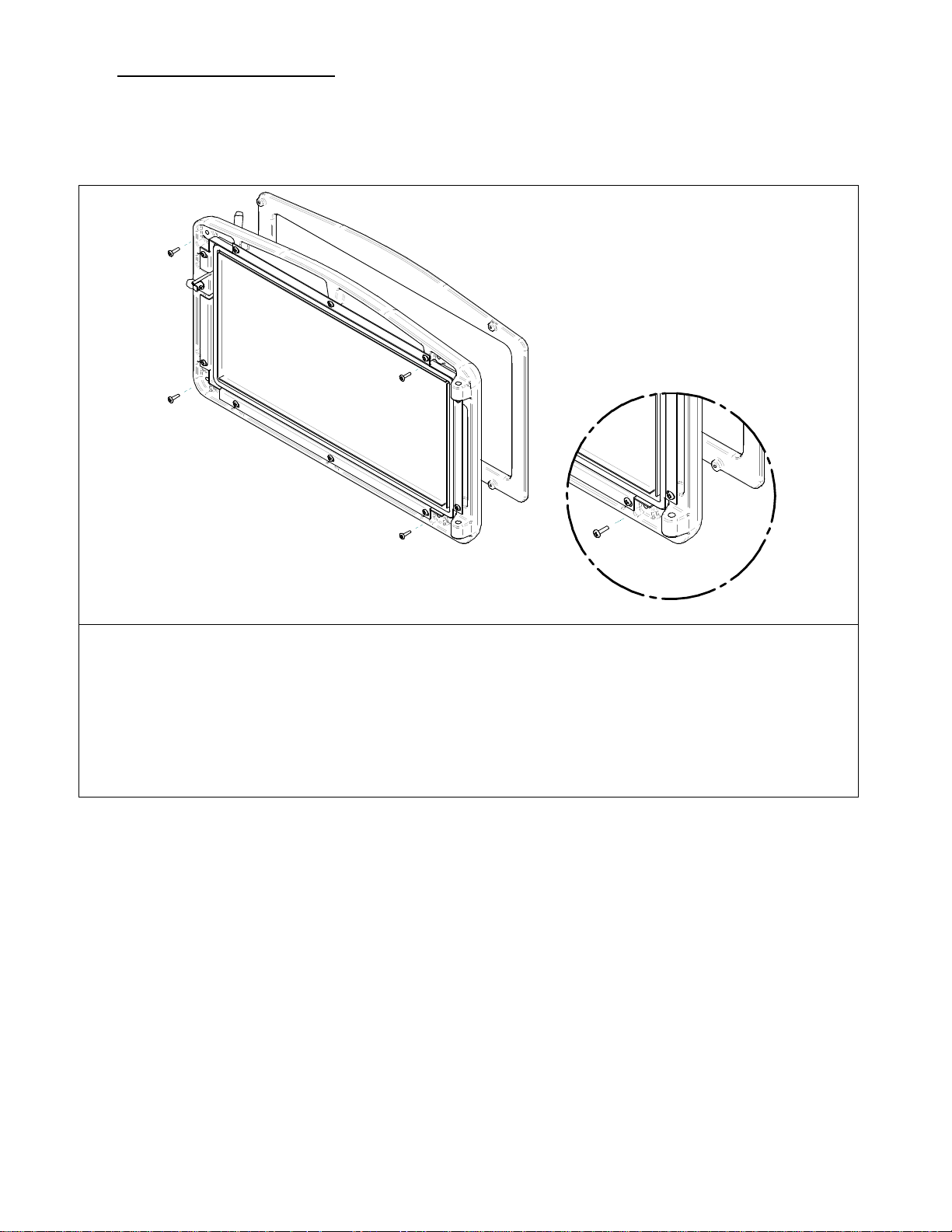
1.3 Door overlay installation
In order to complete the assembly of your Osburn 2400 wood insert, you need to install the door
overlay. See figure 1 below for installation instructions:
Figure 1
1- Position the overlay on the door frame and fix it in place from behind using the 4
screws.
Note: It is not necessary to remove the glass or any other component to install the overlay.
6
Page 7

2.0 INSTALLATION
2.1 Safety information
NOTE: THIS APPLIANCE IS NOT RECOMMENDED FOR USE IN A HOME IF AN OCCUPANT HAS
ANY RESPIRATORY OR ANY OTHER RELATED PROBLEMS.
1. It is important to follow the installation and operation instructions. An improperly installed
or operated insert could result in a safety hazard or fire, or damage to the unit, which
would not be covered by the warranty. Contact local building or fire officials about
restrictions and installation requirements in your area. You should be familiar with the
installation and be sure that the work is done in accordance with this manual.
WARNING: DO NOT INSTALL THIS INSERT IN A SLEEPING ROOM.
2. Where lesser clearances are desired, consult your local authority as regulations may vary
regarding the use of clearance reducing devices. Listed wall and floor shields are
available to reduce clearances, and most building codes provide information on materials
which may be used to reduce clearances.
3. Maintain at least the minimum clearances to combustible material as specified in this
manual. Clearances are measured to the nearest part of the insert (i.e. top edge on the
side). Clearances to any combustibles, when measured directly out from the front, must
be a minimum of 48" (1219mm).
4. Maintain at least the minimum floor protection for combustible floor materials as specified
in this manual. Floor protection to the front is to be measured from the fuel loading door
opening.
5. Osburn recommends that you install a listed smoke detector or alarm in your home.
Normal operation of the insert will have no effect on the detector or alarm.
6. The insert is to be connected only to a lined masonry chimney and masonry fireplace
conforming to building codes for use with solid fuel. Do not remove bricks or mortar from
the existing fireplace when installing the insert.
7. Minimum chimney size is 6" (152mm) diameter. Maintain a 15' (4.5m) minimum overall height
measured from the base of the appliance. Chimneys should be inspected to check for
deterioration and to determine if they meet the minimum requirements, and be upgraded if
necessary. The chimney must extend at least 3' (914mm) above the roof and at least 2' (610mm)
above the highest point within an area of 10' (3m) of the chimney.
8. Do not use makeshift compromises during installation, as they could create a safety
hazard and a fire could result.
9. DO NOT CONNECT THIS APPLIANCE TO THE CHIMNEY OR FLUE SERVING
ANOTHER APPLIANCE.
7
Page 8
2.2 Installation instructions
Inspect the masonry fireplace according to the safety information and fireplace requirements and
have it cleaned and/or upgraded as necessary.
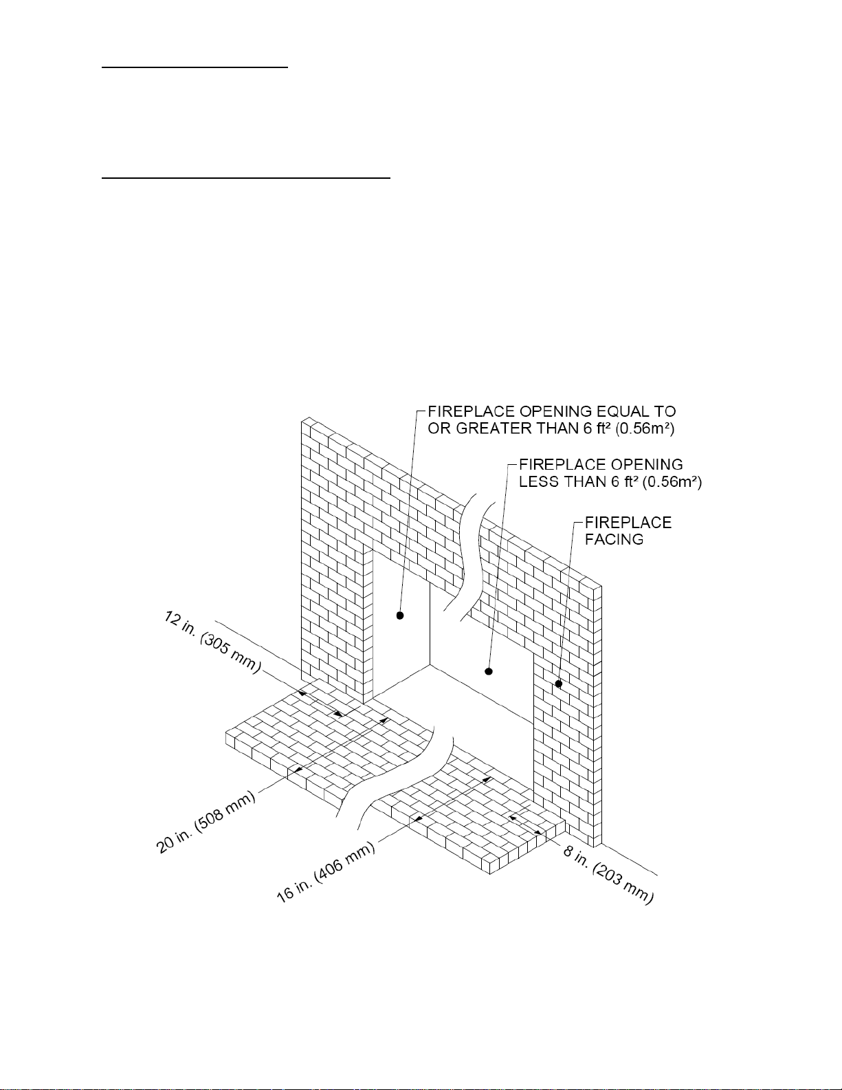
2.3 Compliance of the masonry fireplace
Where the masonry fireplace opening is 6 ft2 (0.56 m2) or larger, the hearth extension shall extend
at least 20'' (508 mm) in front of the facing material and at least 12'' (305 mm) beyond each side of
the fireplace opening. Where the masonry fireplace opening is less than 6 ft2 (0.56 m2), the hearth
extension shall extend at least 16'' (406 mm) in front of the facing material and at least 8'' (203
mm) beyond each side of the fireplace opening.
Note that if you must modify the hearth extension to comply with these measures, depending on
the size of the masonry fireplace opening, the hearth extension must have a minimum of
4'' (102 mm ) thick (see Figure 2.6a and 2.6b.)
8
Page 9
2.4 The masonry fireplace's draft control system
SHELF POSITION
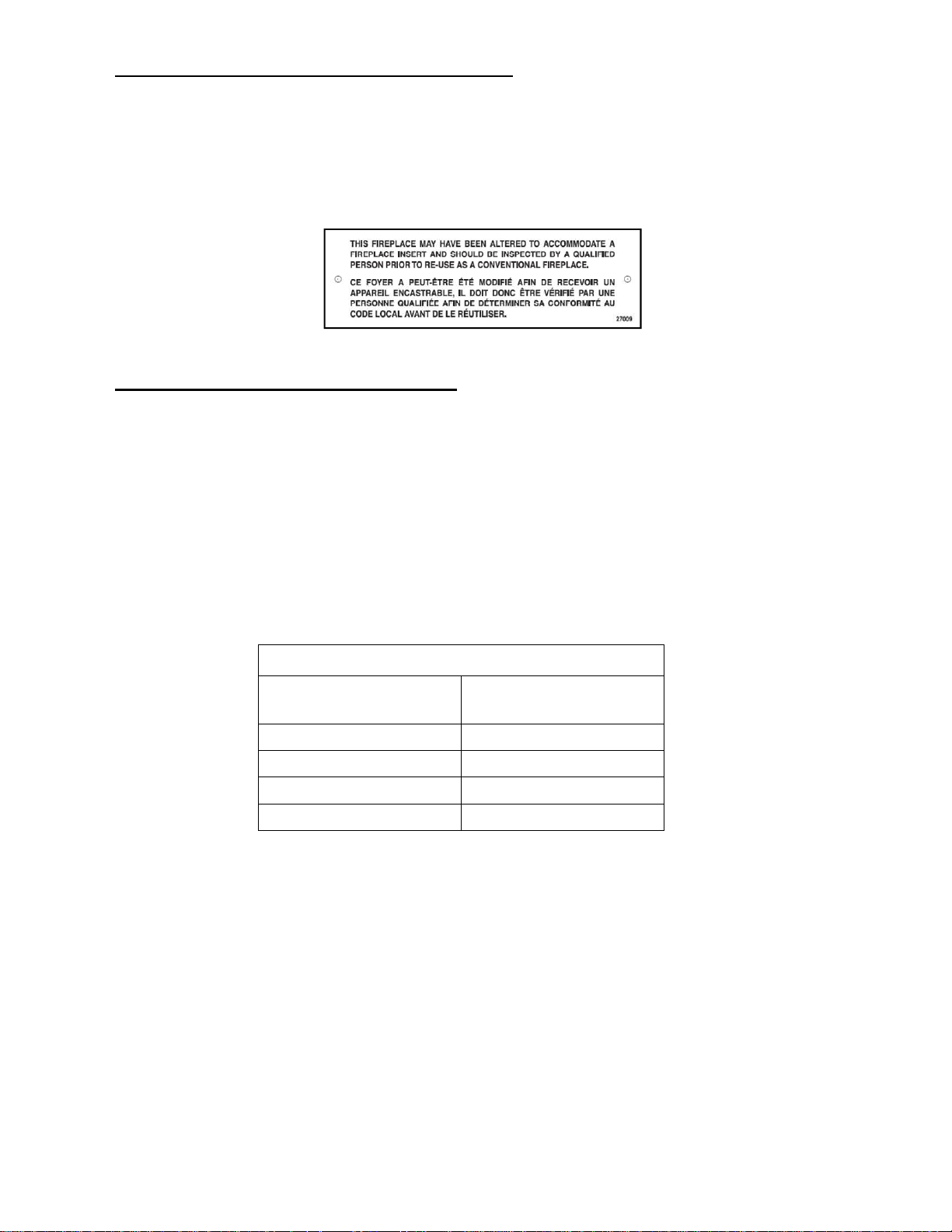
If the fireplace's draft control system is to remain in the masonry fireplace, it must be locked open
for access of the chimney liner or removed entirely. If you remove draft control system from the
masonry hearth, you will need to install the metal plate (27009), supplied with the owner’s manual
kit, indicating that the masonry hearth has been modified. It must be secured inside the masonry
hearth, in a visible place and easy to locate.
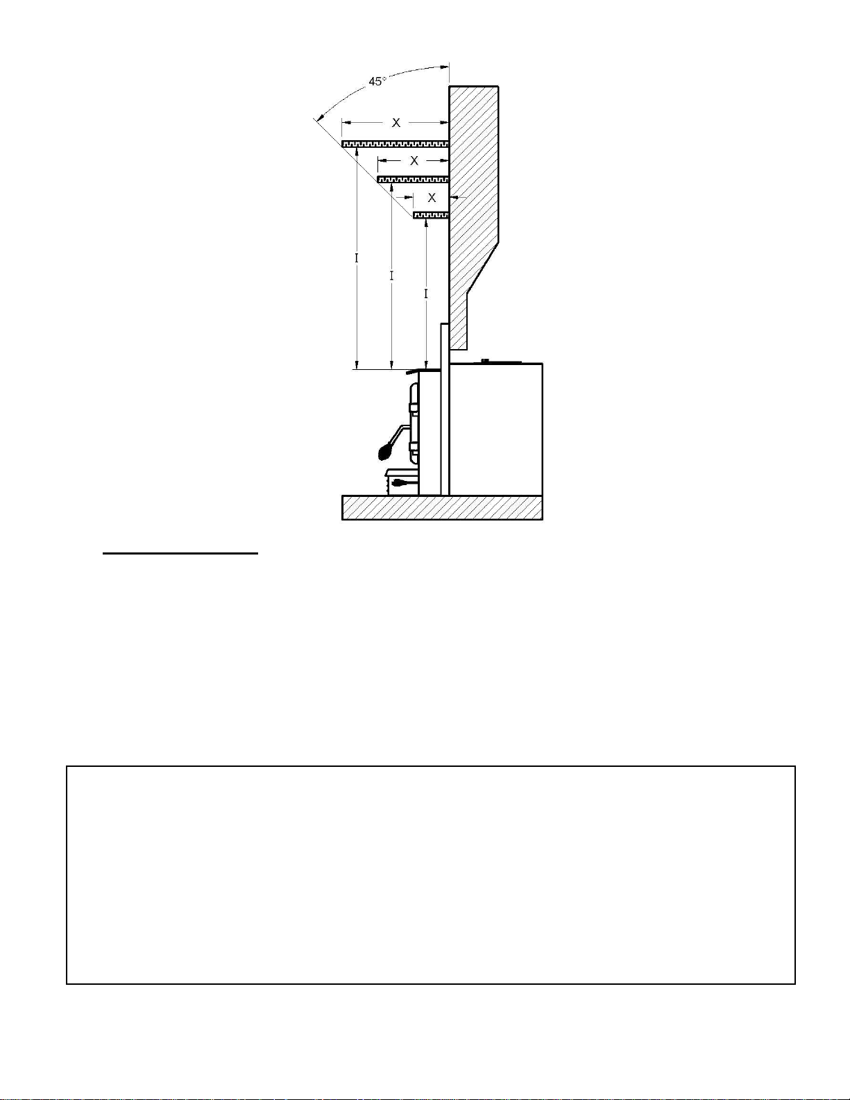
2.5 Compliance of a combustible top shelf
To ensure compliance of an existing top shelf or to install any combustible shelf, refer to table
below and Figure 2.5 for a safe installation or to perform changes if necessary. For example, a
shelf with a 6’’ depth (152 mm) must be installed at least 25 1/2" (648 mm) above the top of the
insert (see Figure 2.5). Different shelf dimensions are listed in the following table in order to
facilitate installation. However, no combustible shelf can be installed at less than 25 1/2"
(648 mm) above the top of the insert. If the depth of the shelf is not listed in the table, add 19
1/2" (495 mm) to the depth of your shelf to obtain the safe positioning of your shelf. For example,
for a 9" (229 mm) shelf, the safe positioning would be 28 1/2" (724 mm) above the top of the
insert (19 1/2" (495 mm) + 9" (229 mm)).
SHELF POSITIONING
MAXIMUM SHELF
DIMENSION (X)
6" / 152 mm 25 1/2" / 648 mm
8" / 203 mm 27 1/2" / 698 mm
10" / 254 mm 29 1/2" / 749 mm
12" / 305mm 31 1/2" / 800 mm
(I)
9
Page 10
2.6 Positioning the unit
In addition to ensuring compliance of the masonry fireplace hearth extension (see Compliance
of the masonry fireplace in Section 2.3), it is necessary to have a floor protection made of non-
combustible materials that meets the measurements specified in table FLOOR PROTECTION
(see Section 2.7). To determine the need to add a floor protection (D) beyond the hearth
extension, you must do the following calculation using the data in Table Data for floor
protection calculation of this section: D = B - (A - C). If the value (D) is negative or zero, you
do not have to add more floor protection in front of the unit, because the masonry fireplace
hearth extension is long enough. If the value (D) is positive, you will need a floor protection in
front of the hearth extension at least equivalent to the result (D).
Here is a sample calculation to determine the need to add a non-combustible materials floor
protection. For someone living in the USA whose fireplace opening is less than 6 ft2 and which
the insert would protrude 3" (76 mm) into the room (C) the calculation would be:
Value D = B - (A - C)
Value D = 16" - (16" - 3")
Value D = 16" - 13"
Value D = 3"
This person should install a non-combustible floor protection of at least 3" (76 mm) in front of
the fireplace hearth extension.
10
Page 11
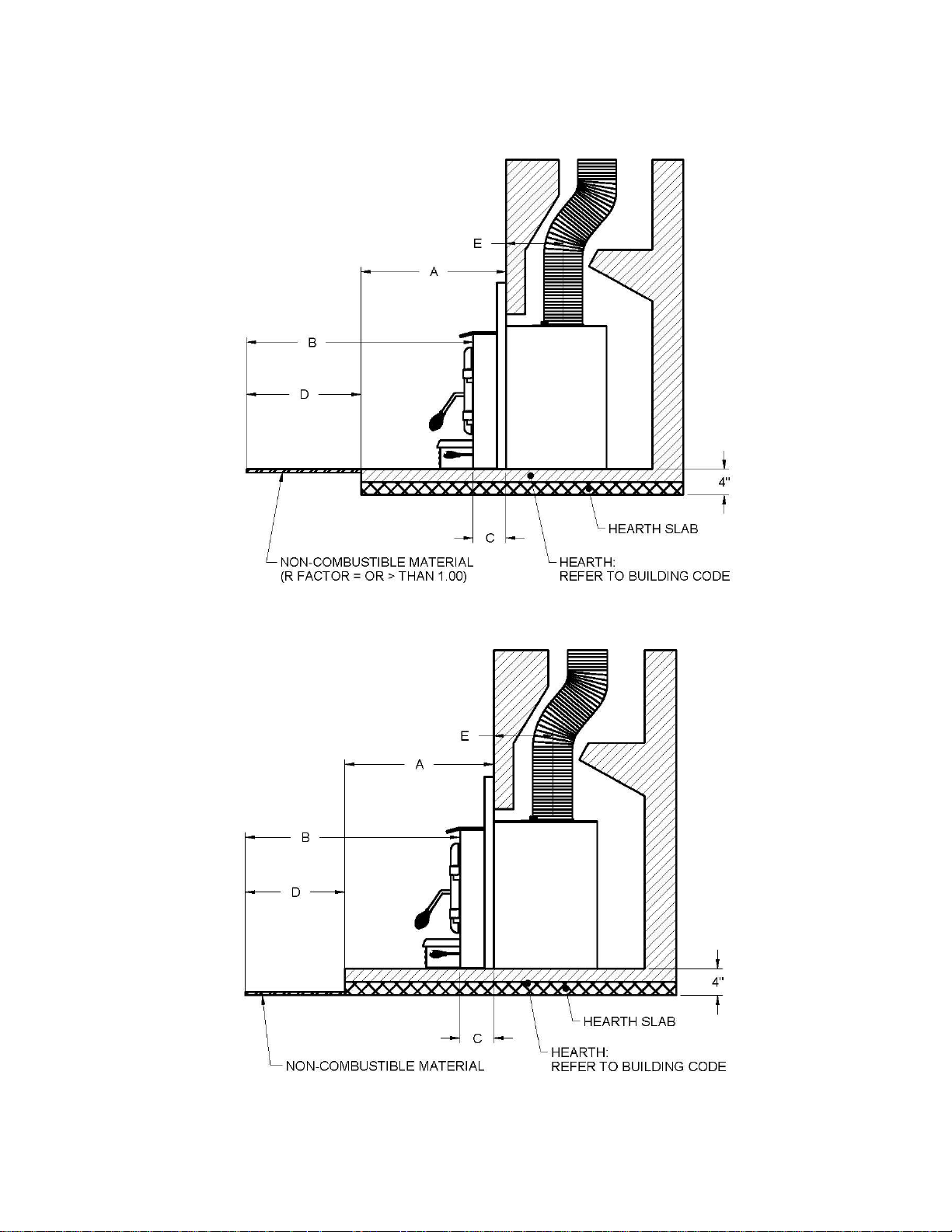
If a non-combustible material floor protection needs to be added in front and level with the hearth
extension masonry fireplace (see Figure 2.6a), an R factor equal to or greater than 1.00 is
required. If the extension of the masonry hearth is raised at least 4" from the floor protection
(see Figure 2.6b), a non-combustible material without an R factor is sufficient.
Figure 2.6a
Figure 2.6b
11
Page 12

The use of an R value is convenient when more than one material is going to be used in the
Example:
hearth extension to cover the combustible surface. This is because R values are additive,
whereas K values are not. To find the corresponding R factor to use for some selected materials,
please see Table Thermal characteristics of common floor protection materials in this
section.
There are two ways to calculate the R factor of the floor protection. First, by adding the R-values
of materials used, or by the conversion if the K factor and thickness of the floor protection are
given.
To calculate the total R factor from R factors of the materials used, simply add the R-values of
materials. If the result is equal to or greater than the R-value requirements, the combination is
acceptable. To know the R-values of some selected materials, see table Thermal
characteristics of common floor protection materials.
Required floor protection R of 1.00. Proposed materials: four inches of brick and one inch
of Durock® board
Four inches of brick (R = 4 x 0,2 = 0,8) plus 1 inch of Durock® (R = 1 x 0.52 = 0.52).
0.8 + 0.52 = 1.32.
This R value is larger than the required 1.00 and is therefore acceptable
In the case of a known K and thickness of alternative materials to be used in combination,
convert all K values to R by dividing the thickness of each material by its K value. Add the R
values of your proposed materials as shown in the previous example.
Example:
K value = 0.75
Thickness = 1
R value = Thickness/K = 1/0.75 = 1.33
12
Page 13

Smaller
Bigger or
Smaller
Bigger or
The more extended the insert, the greater the heat transfer to the room. When installed as an
extended insert, the front edge of the air jacket will be installed flush with the fireplace facing.
Otherwise the unit can be moved back as much as 3 3/4" (95 mm) or any position in between.
The position chosen will depend on your own preference for most installations, your current
configuration, the compliance with the preceding installation instructions and compliance with the
building code requirements. To determine the minimum and maximum protrusion of the insert,
refer to table Data for floor protection calculation.
Data for floor protection calculation
MAXIMUM
EXTENDED
than 6 ft2 *
A
= to 6 ft2 *
INCHES 16" 20"
MILLIMETRES 406 mm
MINIMUM
EXTENDED
than 6 ft2 *
508
mm
A
= to 6 ft2 *
INCHES 16" 20"
MILLIMETRES 406 mm
508
mm
*Refers to masonry fireplace opening.
B
(Note 1)
CAN: 18"
USA: 16"
CAN: 457 mm
USA: 406 mm
B
(Note 1)
CAN: 18"
USA: 16"
CAN: 457 mm
USA: 406 mm
C E AIR JACKET
7" 8 1/2"
Flush with
fireplace
178 mm 216 mm
facing
C E AIR JACKET
3 1/4" 12 1/4"
Back from
fireplace
83 mm 311 mm
facing 3 3/4"
13
Page 14
Thermal characteristics of common floor protection materials*
MATERIAL
CONDUCTIVITY (k)
RESISTANCE (R) PER INCH
PER INCH
THICKNESS
Micore® 160 0.39 2.54
Micore® 300 0.49 2.06
Durock® 1.92 0.52
Hardibacker® 1.95 0.51
Hardibacker® 500 2.3 0.44
Wonderboard® 3.23 0.31
Cement mortar 5.00 0.2
Common brick 5.00 0.2
Face brick 9.00 0.11
Marble 14.3 – 20.00 0.07 – 0.05
Ceramic tile 12.5 0.008
Concrete 1.050 0.950
Mineral wool insulation 0.320 3.120
Limestone 6.5 0.153
Ceramic board (Fibremax) 0.450 2.2
Horizontal still air** (1/8") 0.135 0,920**
* Information as reported by manufacturers and other resources
** For a 1/8" thickness. You cannot «stack» horizontal still air to accumulate R-values; you must separate each later of
horizontal still air with another noncombustible material.
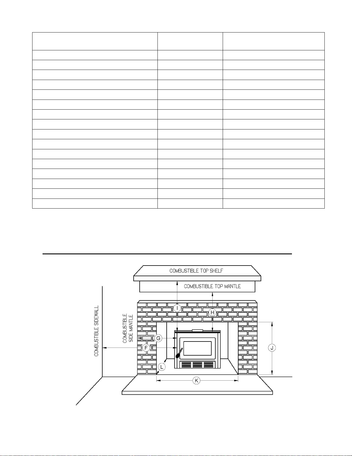
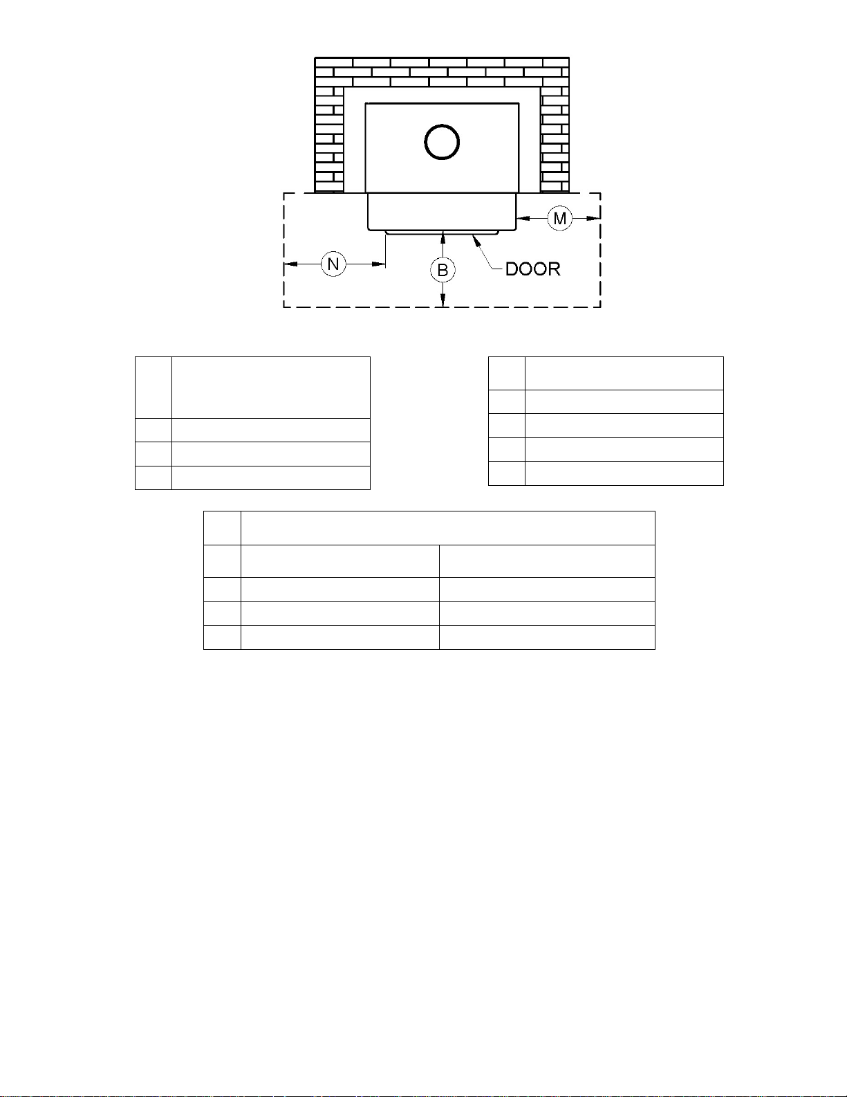
2.7 Minimum masonry opening, clearances to combustibles, and floor protector
14
Page 15
J
K
L
F
G
H
I
B
M
N
MINIMUM MASONRY
OPENING
CLEARANCES
14” (356 mm)
23 1/2" (597 mm)
31 5/8" (803 mm)
16 1/4" (412 mm)
CANADA USA
FLOOR PROTECTOR
8” (203 mm)
20 1/2 ” (521 mm)
25 1/2” (648 mm)*
18’’ (457 mm) – Note1 16’’ (406 mm) – Note 1
8’’ (203 mm) N/A (Canada only)
N/A (USA only) 8’’ (203 mm)
* For a 6" (152 mm) shelf. See Table SHELF POSITIONING (Section 2.5) for other shelf
dimensions.
Note 1: From door opening. The depth of a non-combustible shelf in from of the insert is
included in the calculation of the floor protector’s dimensions.
IMPORTANT: The masonry hearth should be at least 4 inches (102 mm) higher than the
combustible floor in front of it. If the hearth elevation is lower than 4 inches, the noncombustible floor protector in front of the insert should have an R value equal or greater than
1.00.
15
Page 16
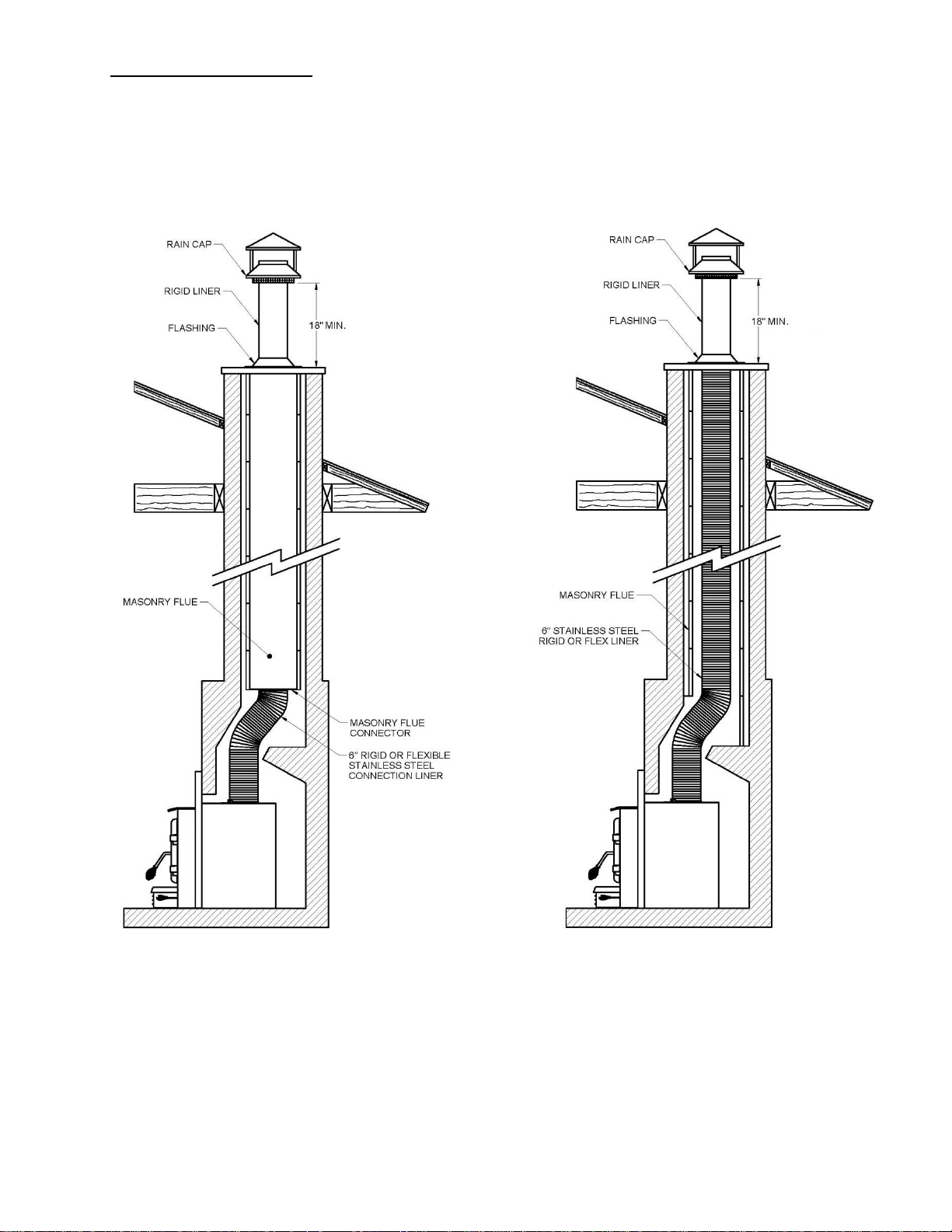
2.8 Connector installation
A masonry flue connector may provide acceptable performance (Figure 2.8a); however, we
recommend the use of a chimney liner (rigid or flexible) to ensure satisfactory performance
(Figure 2.8b). To ensure an optimal draft, we also strongly recommend adding a minimum of
18” rigid liner between the roof flashing and the rain cap. Slip connectors for continuous liners
should also be installed. Use Listed Chimney Liners – UL1777, CAN/ULC-S635.
Figure 2.8a Figure 2.8b
ATTENTION INSTALLER: When positioning the unit in a fireplace opening prior to the flue
installation, install the insert into the opening until the top lip of air jacket is flush with fireplace
facing.
If lag-bolts and anchors are to be used to secure the insert, the whole locations should be
marked with the unit in place. Remove the insert and locate the anchors.
16
Page 17
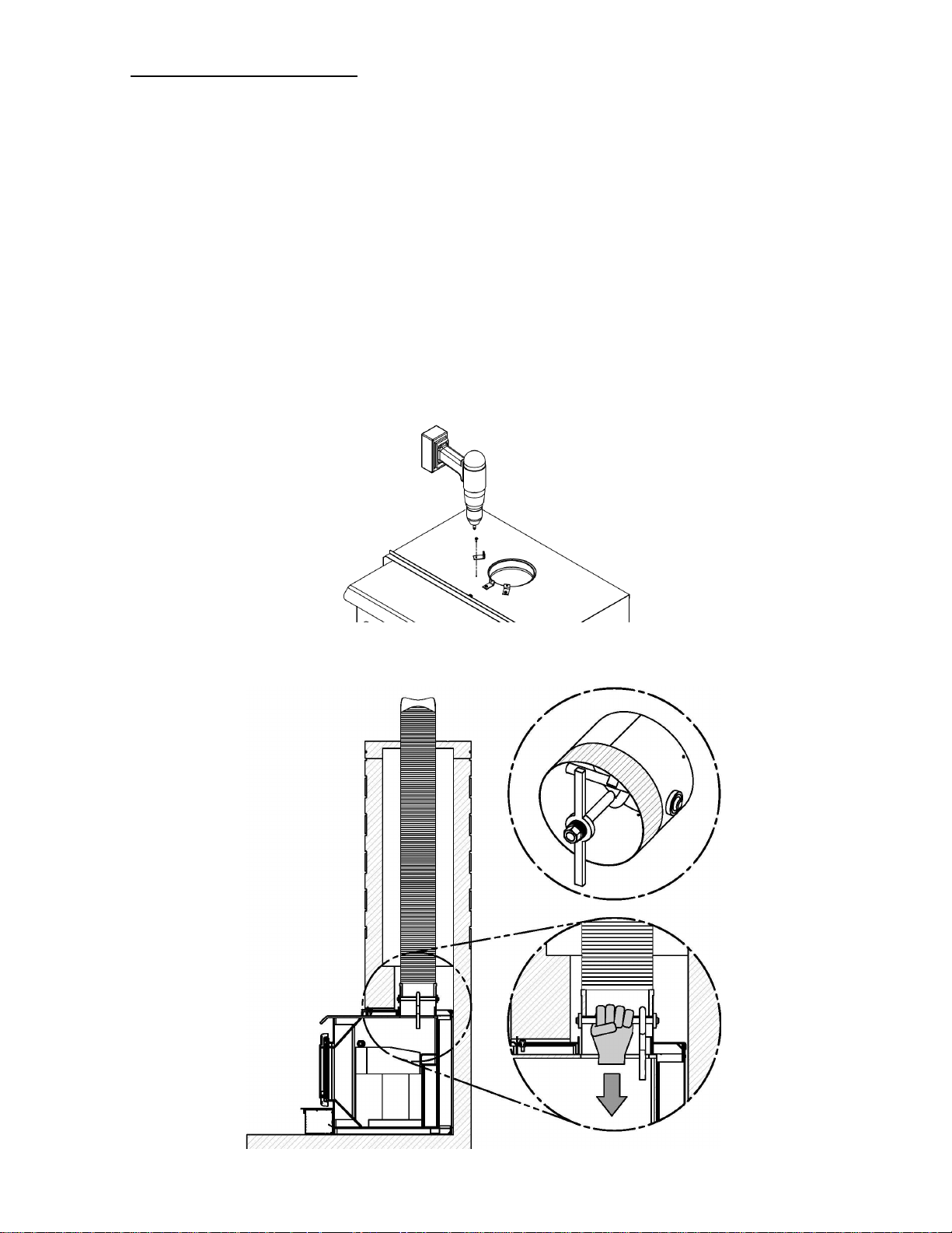
2.8.1 Chimney liner installation
To install of the chimney liner, the preferred methods are those found in Section 2.8.1.1. Use a
liner offset adapter (Section 2.8.1.2) only as a last resort.
2.8.1.1 If the chimney liner does align with the insert’s flue outlet, you have two options:
A) Install the chimney liner starter adapter, provided with the chimney liner. Follow the
chimney liner starter adapter manufacturer's instructions.
In order to connect the chimney liner starter adapter to the flue outlet, you can install the
brackets with the screws that are in the instruction manual kit.
Using a powered driver, secure the three brackets with the three screws provided 30131
on top of the insert in the three holes in front of the flue outlet. The long end of the
brackets must be attached to the insert. Insert the chimney liner into the flue collar of the
unit and secure the liner to the brackets with three self-tapping screws (not included).
B) You can get from your dealer a liner fixation system (AC02006), sold separately. Follow
the installation instructions provided with the liner fixation system.
17
Page 18
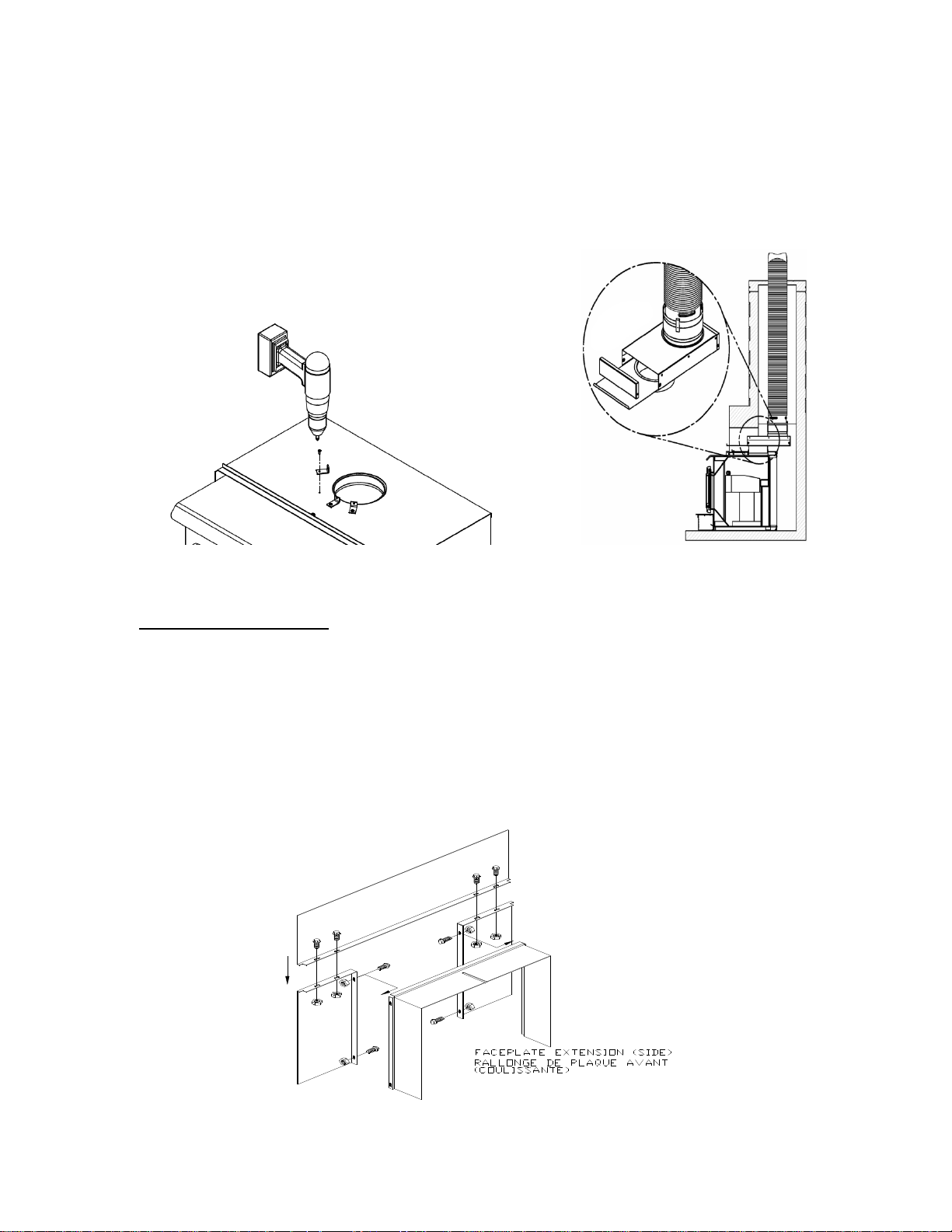
2.8.1.2 If the chimney liner does not align with the insert’s flue outlet:
You can get a liner offset adapter (AC01370), sold separately. If you must install a liner
offset adapter, using a powered driver, secure the three brackets with the three screws
provided 30131 on top of the insert in the three holes in front of the flue outlet. The long
end of the brackets must be attached to the insert. The brackets and screws are in the
insert’s instruction manual kit. Then follow the instructions in the manual provided with the
liner offset adapter kit.
2.9 Faceplate installation
Remove the faceplate panels from their box and assemble according to these faceplate
instructions.
A. Remove the slide from within the air jacket.
B. Place the faceplate face down on a flat, nonabrasive surface (see Figure 2.9a) so that
the sides are a bit towards the middle.
Figure 2.9a
18
Page 19
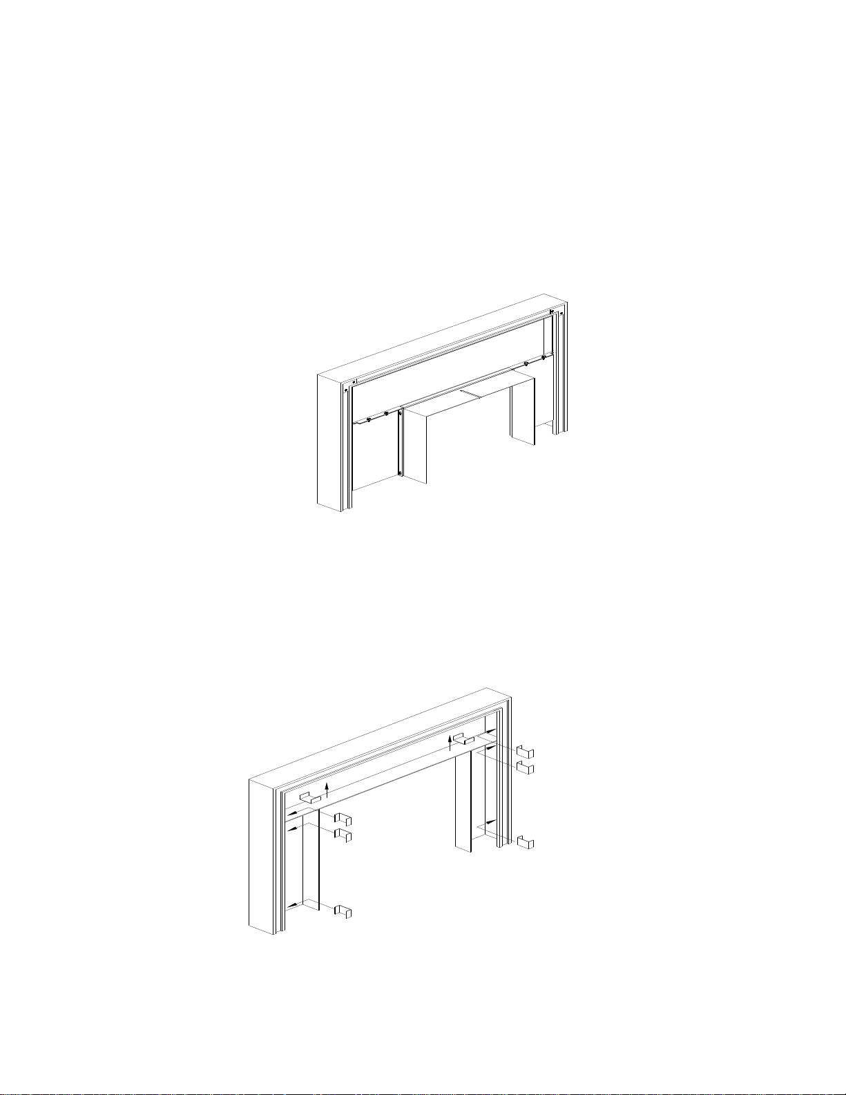
C. Place the slide onto the faceplate so that the bends of the faceplate pieces go inside of
the slide.
2400 INSERT FACEPLATE BOLT ASSEMBLY:
Contents: 8 - 1/4" x 1" (6.25 mm x 25 mm) carriage bolts
8 - 1/4" (6.25 mm) flat washers
8 - 1/4" (6.25 mm) hex nuts
D. Line up the holes by pushing the sides out and install (smooth heads inside) all the bolts
loosely. Line up the edge of the faceplate top and side, tighten the two bolts joining
them, and then tighten the side bolts. Tighten the bolts on the other side in the same
manner (see Figure 2.9b).
Figure 2.9b
Installation on faceplates: Attach the mitered corners of the trim together using the corner
brackets. Slide the assembled trim over the edge of the faceplate. See Figures 2.9c & 2.9d.
Attach the left and right side to the top with corner brackets supplied. Slip the trim over the
faceplate and snap the eight trim retainers in place (see Figure 2.9c).
Figure 2.9c
19
Page 20
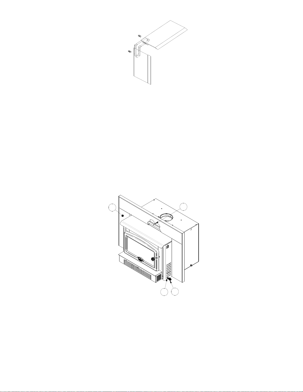
Back view of faceplate
Figure 2.9d
Lift the insert into the fireplace. Square the insert to the face of the fireplace by adjusting the
leveling legs on the sides at the rear of the insert. Check that the throat connector is in line.
If there is space to push the connector down from above, do so. Reach in through the insert and
pull the throat connector down into place. If you are securing the connector to the flue collar with
the screw, do that now.
Push the air control (A) in, all the way. Slide the adjustable faceplate sleeve back into its original
location until the faceplate fits tightly against the fireplace facing. See Figure 8. One 7/16"
(11mm) open end wrench should be used to turn the nut (B), located above the cook top in the
centre, up so that it securely fastens the adjustable faceplate sleeve to the top air jacket. Take
the air control slider spring handle (C) from the firebox and turn it onto the 1/4" diameter (6mm)
air control rod (A).
D
C
B
A
Figure 2.9e
Lift the insert into the fireplace. Square the insert to the face of the fireplace by adjusting the
leveling legs on the sides at the rear of the insert. Check that the throat connector is in line.
If there is space to push the connector down from above, do so. Reach in through the insert
and pull the throat connector down into place. If you are securing the connector to the flue
collar with a screw, do that now.
20
Page 21

2.10 Baffle & brick installation
CAUTION: Operation of your Osburn insert without the baffle may cause unsafe and hazardous
temperature conditions and will void the warranty. NOTE: Before installing the
firebrick, check to ensure that none are broken or damaged in any way. If so, have
the damaged ones replaced. Check the firebrick for damage at least annually and
replace any broken or damaged ones with new ones. Inspection and cleaning of
the chimney is facilitated by the removable baffle.
The stove is shipped with all firebricks in place except for the top 3 at the rear of the firebox and
the top sides (2 per side, 1 full and 1 partial). The balance of the loose bricks are for the baffle.
Install three top rear firebricks. The two full 9" (229 mm) bricks are on either side and are to be
installed first. Then place the 7" (178 mm) brick in the center . Install the full 9" (229 mm) bricks
on each side toward the rear of the firebox. After the 9" (229 mm) bricks are in place, install the
partial 5 1/2" (140 mm) bricks on each side. The firebox bricking procedure will now be
complete.
To install the baffle, follow the instructions on the next page. To remove, reverse the procedure:
21
Page 22
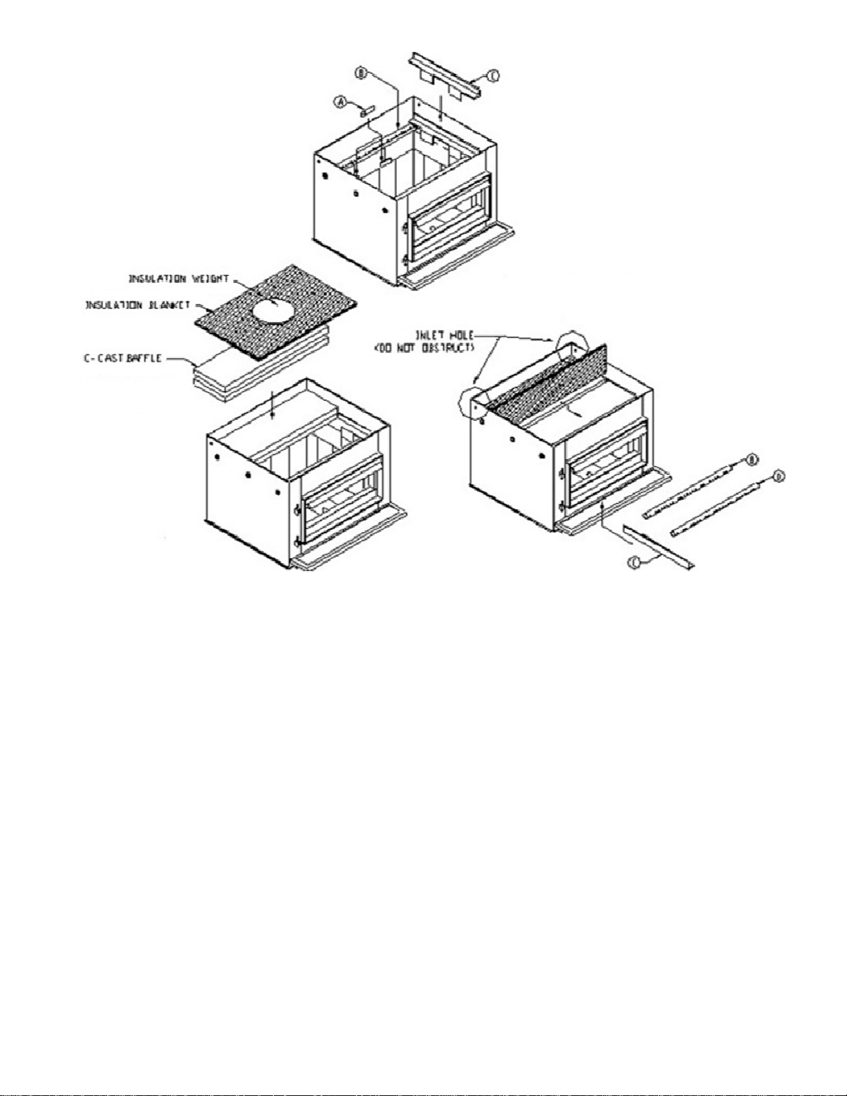
Figure 2.10a
1- First, install the rear secondary air tube (B) in the firebox. Refer to figure 4.5:
‘’secondary air tube replacement’’ in section 4.0 (Maintenance).
2- Install the stainless steel brick retainers (C) on the rear centre bricks intersections.
3- Install the first side baffle support (C) on one side of the firebox as shown in figure
2.10a.
4- Put the c-cast boards on top of the rear secondary air tube. The c-cast boards must be
placed next to each other (not stacked). Put the insulation blanket on top of the c-
cast boards as shown in figure 2.10a. Place the insulation weight at the top back
centre of the insulation blanket lined up with the flue outlet.
5- Install the second side baffle support (D) on the other side of the firebox.
6- Install the two remaining secondary air tubes and push the baffle assembly towards
the back of the unit.
NOTE: As with all fibrous materials, avoid inhaling any airborne fibers.
NOTE: Make sure that rear inlet holes are not blocked by the insulation blanket.
22
Page 23
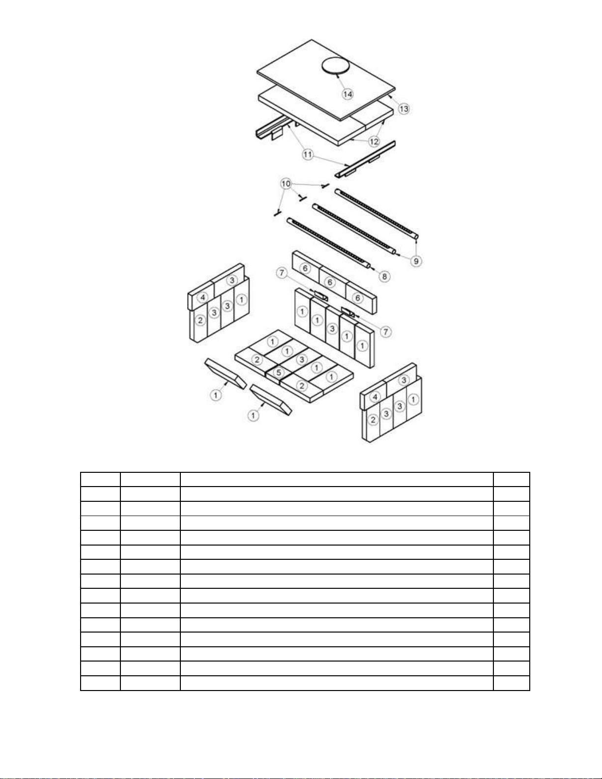
Figure 2.10b
ITEM PIECE #
DESCRIPTION QTY
1 29020 4 1/2" X 9" X 1 1/4'' REFRACTORY BRICK 12
2 PL36058 4" X 9" X 1 1/4'' (COUPE 1'' X 1'') REFRACTORY BRICK 2
3 29011 4" X 9" X 1 1/4'' REFRACTORY BRICK 8
4 PL36014
5 PL36048
4" X 6 1/2" X 1 1/4'' REFRACTORY BRICK 2
4" X 4" X 1 1/4'' REFRACTORY BRICK 1
6 29001 4" X 8" X 1 1/4'' REFRACTORY BRICK 3
7 PL39027
8 PL39015
9 PL39018
REAR BRICK RETAINER 2
FRONT SECONDARY AIR TUBE 1
REAR SECONDARY AIR TUBE 2
10 30068 1/8'' X 1 1/2'' STAINLESS STEEL COTTER PIN 3
11 PL39013
12
21297
13 PL39047
14 PL34026
16 3/8'' X 25'' X 1/2'' BAFFLE INSULATION BLANKET 1
2400 SERIE BAFFLE SIDE HOLDER 2
23 7/8'' X 8 1/4'' X 1 1/4'' C-CAST BAFFLE
INSULATION BLANKET WEIGHT 1
2
23
Page 24

3.0 OPERATION
3.1 Safety information
1. This insert is designed for safe operation
modifying the unit or the installation without proper authorization will void the certification,
warranty, and safety listing, and may result in a safety hazard.
2. For safety reasons, never leave the unit unattended with the door open or ajar. An open
door, and especially a door partially open or cracked, if left for longer than required for good
ignition can potentially result in unsafe chimney temperatures, and if left unattended, hot
embers or ignited fuel may fall out of the unit. Prolonged door open operation is not
necessary provided the unit has been properly installed and dry kindling is used to start the
fire.
3. Do not abuse the unit, either by over firing or by using wood or combustibles with salt
content, or harmful chemicals. Misuse is not covered by warranty.
4. Even though your Osburn has been specifically designed and tested to prevent smoke
spillage, always open the door slowly as this will minimize the likelihood of smoke spillage or
a back draft causing flame or smoke to spill into the room.
5. Never use gasoline type lantern fuel, kerosene, solvents, charcoal lighter fluid, or
inflammable liquids to start or "freshen" a fire in the insert. Keep all such liquids well away
from the insert while it is in use.
6. All insert surfaces become very hot during operation. Care is needed, especially with
children, to avoid contacting these surfaces.
7. Do not elevate the fire by means of grates, and irons or other means.
8. CAUTION: DO NOT OVER FIRE THIS HEATER. Do not burn fuel in the insert at a rate
higher than that which will cause the ember bed level to exceed half the door opening
height. If burning hot fires regularly, purchase an insert top thermometer, and do not exceed
840o F (450 oC) as measured on the Cooktop. If the door handle of the insert becomes
excessively hot to the touch, consider this to be an indication of over firing. Over firing can
result in a safety hazard and can permanently damage the insert and chimney. This
damage is not covered by the warranty.
9. Although the ceramic glass is extremely durable under any normal use, a few precautions
are required. Do not attempt to push logs further into the fire by using the door, as the glass
may break if it is heavily contacted by any solid object.
W
HEN BURNING CORDWOOD ONLY
. Altering or
24
Page 25

10. Never operate the insert with the door open, or cracked slightly open, except briefly during
the lighting operation, and during refuelling. Leaving the door open continuously could
seriously overheat the chimney and adjacent combustibles. Do not operate the insert if
there is an abnormal air leakage into the unit, such as through deteriorated gaskets or
cracked or broken glass. Do not operate the insert without a door gasket. Leakage can
result in overheating, or in very airtight homes, could possibly cause smoke spillage into the
room. Smoke may contain carbon monoxide, which is poisonous, and in sufficient quantities
is a health hazard.
11. We recommend that you have a fresh air or make up air supply for the insert. In Canada
this is a building code requirement. If this is not done, it could cause poor air quality in the
home, poor and incomplete combustion, and poor efficiency in the insert.
3.2 Fuel
1. Fuel for the insert must not be stored closer than the required clearances to combustibles
and not in the space required for ash removal.
2. Your Osburn insert is designed to burn
C
ORDWOOD FUEL ONLY
. Do not burn coal, charcoal, or
trash in the unit. Highly flammable items such as trash may ignite creosote in the chimney,
resulting in a chimney fire. Never burn salt wood, beachwood, chemically treated wood, or
wood removed from salt water, since the deposits left will deteriorate the firebox. Damage
caused by chemicals or salt is not covered under warranty.
3. Seasoned dense wood is recommended. Wood should be air dried in a covered ventilated
area for six months to a year or more. This reduces the moisture content of the wood,
resulting in better insert performance. Wood species with moisture content of 20% or less
are ideal. Dry seasoned wood can be distinguished from green wood by the checks or
cracks in the ends.
4. Wet or green wood will tend to cause the fire to smoulder, producing large amounts of
creosote. Creosote build-up could result in a chimney fire. This wood will also prove difficult
to keep burning properly, and fires will tend to go out. Green wood produces very little heat,
and sometimes causes customers to think that the insert does not work. If you must burn
wet wood, use only small amounts mixed with dry wood.
5. Decayed wood or low-density wood has very little energy content or heating value, and will
not burn satisfactorily for long periods of time.
An example of the energy values of some common wood fuels is given in the following table. For
recommended wood sizes, refer to the specifications.
25
Page 26

Common Heating Values of Cordwood
Hardwoods Million Btu/Cord Softwoods Million Btu/Cord
Birch 23.6 Douglas Fir 20.6
White Oak 28.3 Hemlock 17.1
Alder 17.6 Jack Pine 18.4
3.2.1 Simple wood moisture test
Add one large piece of wood to the top of an established fire. If it starts to burn on three sides
within one minute, it is dry and seasoned and right for burning. If it turns black and starts to burn
in three minutes, it is damp. If it turns black and does not start burning until after five minutes, it
is green and wet. If it hisses at any time the wood is soaked and will not burn until excess
moisture is boiled away.
3.3 Notes about first firing
Before firing ensure that the room is well ventilated. Curing the paint is recommended to
preserve the best quality finish. Heating the insert too intensely on the first fire will dull and
lighten the colour on overheated areas, and cause smoke and odour to be emitted into the room.
To cure the paint, the first two fires should be burned for only about twenty minutes each.
Allow the insert to get warm only, but not hot, i.e. 250 oF (120 oC) as measured by an insert top
thermometer, then allow the insert to cool down. Light a third fire and burn it for about forty
minutes to 450 oF (230 oC) or less. Once again cool the insert to room temperature, then
operate it according to the following instructions. This extra care will result in a more durable,
and uniform finish.
3.4 Lighting a fire
1.
Place enough crumpled balls of newspaper or other paper into the insert to cover the bottom of the
firebox.
2. Place small dry kindling on the crumpled paper.
3. Place larger dry kindling on top of the small kindling.
4. Open the draft control fully to the right (located on the right side of the faceplate, Figure 3.1)
5. Light a fire at the bottom of the crumpled paper and close the door. If the fire tends to go out,
momentarily hold the door slightly ajar to fan the fire. As soon as the fire catches hold, close the
door.
26
Page 27
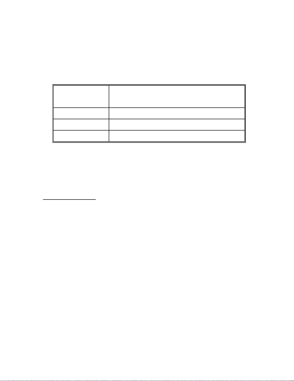
6. Ideally the large kindling should be burned until a thick bed of red embers is obtained. At
that point, add cordwood fuel and continue to operate the draft control wide open until the
fire is well established. Once the firebox is hot, the draft control can be partially closed by
moving the knob to the left to adjust the intensity of the fire.
Use table below to adjust the draft control to the desired burn rate:
Draft Settings
BURN RATE
Low & Medium Low
Medium
Medium High
High
Closing the draft control down too soon will lower combustion efficiency, and may result in
creosote build-up in the chimney (which could lead to a future chimney fire).
Caution:
3.5 Maintaining the fire
The Adjustment Range Should Not Be Altered For Increased Firing For Any Reason.
Gently push the draft control rod all the way in
Gently pull the draft control rod out to approx. 1/8"
Gently pull the draft control rod out to approx. 1/2"
Gently pull the draft control rod all the way out
DRAFT SETTINGS
Your Osburn insert will work best if a thick bed of hot embers is maintained in the bottom of the
firebox, and a minimum of two large pieces of seasoned fuel are added. Combustion efficiency
is largely related to establishing a hot ember bed, and hot firebox temperatures. The quicker the
insert and fuel get up to operating temperature, the better. A small intense fire is preferred to a
large smouldering fire, both to improve combustion efficiency and to reduce the amount of
creosote emitted. The best performance will be achieved by adding relatively small amounts of
fuel to a well established ember bed, and then operating with the air inlet control open long
enough to achieve a hot fire. Cordwood should be placed with air in between individual pieces.
Use a poker to make an air channel in the embers below the wood, this will allow air to flow
under the wood for a more efficient burn.
Extended burn times can be accomplished by first operating the insert on a full load with the air
inlet controls wide open. Once the fire is well established, and the moisture has been driven out
of the wood, reduce the air control to a lower setting. The unit should then burn cleanly without
smoldering. If the fire smolders without flame, re-establish a hotter fire before moving the air
control to the lower setting. A yellow flame burning in the top of the firebox is a good indication of
a clean efficiently burning fire.
27
Page 28
Refuelling technique is important for good performance. The best efficiency and performance
from your insert can be achieved by adding partial loads of fuel and allowing them to get up to
operating temperature before adding additional fuel. Adding a large amount of fuel at one time
will increase the time required to get the fuel up to its ignition temperature, and an extended time
to reach optimal performance. When refuelling, open the air control or hold the door partially
open 1” (25 mm) or less, long enough (less than 5 minutes) so that the fire has well-established
flames. When refuelling, care is required to ensure that fuel or embers do not fall out of the door
opening.
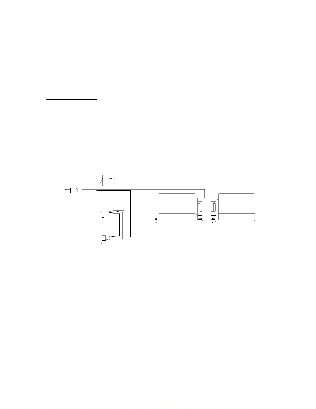
3.6 Blower operation
Allow the insert to heat up to operating temperature before turning on the blower. Increased
airflow from the blower will remove heat and affect the combustion efficiency during start-up.
For this reason we equipped the blower assembly with a heat sensor which will activate the
blower at the selected speed. The 3 position rocker switch is to control the blower speed « Low
towards the bottom – Off in the middle – Hi towards the top », « Low » being the minimum air
flow, « Off » to stop air circulation and « Hi » being the maximum air flow. If you prefer to
control the blower manually and at any time you will need to bypass the heat sensor. The heat
sensor is bypassed when the 2 position rocker switch is set to OFF.
The blower should be kept clean and dust free. Life of the blower will be shortened if operated
in a dust filled environment, or if the blower is overheated by restricting air supply. Stalling the
motor, or over firing the insert with the blower turned off will also damage the blower. The
blower must not be over heated.
28
Page 29

4.0 MAINTENANCE
4.1 Care and cleaning
Clean the insert frequently so that soot, ash and creosote do not accumulate. Do not attempt to
clean the insert, glass or door when the unit is hot. Special care must be taken with Gold
surfaces in order to maintain the finish at its original brilliance. Do not use an abrasive glass
cleaner, which will scratch the glass or gold finish. Use only a soft clean damp cloth on the door,
since some cleaners may remove the plating or paint.
4.1.1 Glass cleaning
Under normal operation the stove is designed to keep the glass clean. Glass cleaning may be
required when burning damp wood and/or when burning slow fires. Generally if the glass is not
staying clean then the unit is being under fired. Dirty glass may be self-cleaned by burning a hot
fire (i.e. dry wood and opened draft controls) for a couple of hours. Good burning techniques will
result in clean glass.
Hand clean the glass only when the fire is out and the insert is cold. A light film can usually be
cleaned with paper towel and water. If heavy cleaning is required, a ceramic glass cleaner or
polish is recommended, and should be rinsed off with water for best results.
4.2 Ash removal
CAUTION: Ashes can start fires, even after several days of inactivity. Never dispose of ashes
in a combustible container. Remove ashes only when the insert and ashes are
cold.
Ashes should be removed from the insert frequently. When ashes are removed, they should be
placed in a metal container with a tightly fitting lid. The closed container of ashes should be
placed on a non-combustible floor or on the ground, well away from all combustible materials,
pending final disposal. If the ashes are disposed of by burial in soil or otherwise locally
dispersed, they should be retained in the closed container until all cinders have thoroughly
cooled. Do not place other waste materials in the metal ash container.
29
Page 30

4.3 Chimney cleaning
Regular chimney maintenance, as well as good burning practices, are required to prevent
chimney fires. The chimney and the chimney connector pipe must be maintained in good
condition and be kept clean for optimal safety. The chimney should be checked regularly for
creosote build-up. Inspection and cleaning of the chimney can be facilitated by removing the
baffle.
CAUTION: OPERATION OF YOUR OSBURN 2400 WITHOUT THE BAFFLE MAY CAUSE
UNSAFE AND HAZARDOUS TEMPERATURE CONDITIONS AND WILL VOID
THE WARRANTY.
Contact your local, municipal, state, or provincial fire authority for information on how to handle a
chimney fire before there is any chance that it may happen.
4.4 Creosote – formation and need for removal
When wood (especially green wood) is burned without adequate heat or air supply, it produces
tar and other organic vapours (smoke), which combine with expelled moisture to form creosote.
The creosote vapours condense in the relatively cool chimney flue of a slow-burning fire. As a
result, creosote residue accumulates on the flue lining. When ignited, this creosote makes an
extremely hot fire, which could be hazardous. Check frequently for creosote build-up. In the
event of a insert or chimney component failure, replace only with equipment that is equivalent to
the original, available from your Osburn dealer.
Your Osburn insert has been designed to reduce the amount of creosote produced. Even so,
the chimney connector pipe and chimney should be inspected at least once every two months
during the heating season to determine if a creosote build-up has occurred. If creosote has
accumulated, it should be removed to reduce the risk of chimney fire. Call a professional
chimney sweep, or go to your local Osburn dealer and purchase a chimney brush, and have the
chimney cleaned.
30
Page 31
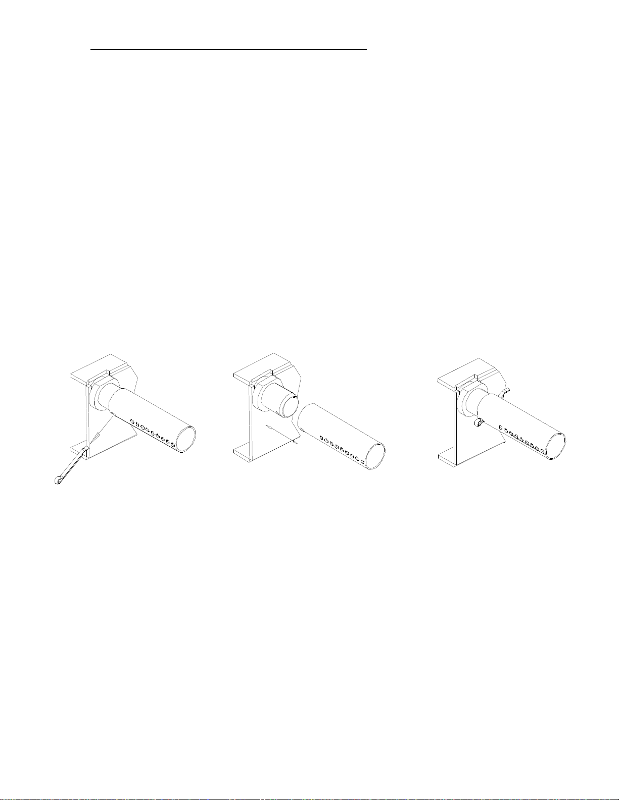
4.5 Secondary air tube replacement (see Figure 4.5)
1. Remove cotter pin at LH end of tube.
2. Slide tube to right and lower tube end below LH plenum.
3. Slide tube to left to remove.
4. Reassemble in reverse order using a new cotter pin. The cotter pin is a hammerlock style
and locks into place by hitting the head sharply with a hammer.
5. Note that any tube can be replaced without disturbing the baffle.
Important Notes:
The air tubes are identified for placement as follows:
Front to back: Tube No. 1 30 Holes of .188” diameter
Tube No. 2 32 Holes of .156” diameter
Tube No. 3 32 Holes of .156” diameter
Figure 4.5 – Secondary air tube replacement
31
Page 32

5.0 TROUBLESHOOTING
Symptom Possible Cause
1. Down draft
2. Chimney blocked 2. Clean chimney
I Smoke in
room
II Wood burns
poorly or is
slow to start
or no heat
III Dirty glass
IV Wood burns
too fast
3. Chimney damper shut 3. Open or remove
4. Baffle out of position 4. Correctly position baffle
5. New paint is curing 5. Refer to instructions
1. Low draw
2. Wet or decayed wood
3. Blocked intake air
1. Insert is being under fired
1. Too much draft in chimney
Corrective Action
1. Upgrade chimney
damper
1. Upgrade chimney
2. Use proper fuel
3. Check intake air supply
by removing blower
from insert and opening
a window
1. Refer to instructions
1. Contact a qualified
technician
32
Page 33

6.0 SPECIFICATIONS
TEST STANDARDS ULC S628 (CSA B366.2) residential
UL 1482 residential
Oregon Department of Environmental
Quality
U.S. Environmental Protection Agency
(Phase II, 1990)
Heating capacity* – BTU/hr., EPA test wood: 44,100 BTU.
Heating capacity* – BTU/hr., seasoned cordwood: 100,000 BTU/h.
Maximum recommended heating area : 1000 to 2,700 square feet
Optimum efficiency: 78%
*Why is the BTU indicated on the EPA label smaller than the one advertised?
You will notice a difference between the BTU output as indicated on the unit’s white EPA label affixed to the glass and the BTU
as advertised on our web site and/or product literature. The maximum BTU output we advertise for this unit is what will be
obtained with a full load of seasoned cordwood inserted inside the firebox. The EPA output, on the other hand, is what has
been obtained during emissions testing. The EPA test procedure requires that a special type of wood be used and positioned
inside the firebox in a manner that does not represent the way the firebox volume would normally be utilized using seasoned
cordwood. The EPA test load is typically much smaller. Hence, the BTU as per the EPA label is reduced. The BTU output that
should be considered by a normal user is the one we advertise for seasoned cordwood.
SHIPPING WEIGHT 504 lbs. (229 Kg)
COOK TOP HEIGHT 21 3/8" (543 mm)
OVERALL HEIGHT 23 1/4" (590 mm)
OVERALL WIDTH 31 1/8" (790 mm) with levelling nuts
29 5/8" (752 mm) without levelling nuts
OVERALL DEPTH 27 7/8" (733 mm)
COOKTOP DEPTH INTO
ROOM, EXTENDED 7 13/16" (198 mm)
COOKTOP DEPTH INTO
ROOM, FLUSH 4 1/4" (108 mm)
FIREBOX SIZE 3.2 cubic feet
DOOR OPENING SIZE 8" x 19.5" (203 mm x 495 mm)
MAXIMUN LOG SIZE 21" (533 mm)
FLUE OUTLET 6" (152 mm) diameter
33
Page 34

OSBURN LIMITED LIFETIME WARRANTY
•
•
The warranty of the manufacturer extends only to the original retail purchaser and is not transferable. This warranty covers brand new products
only, which have not been altered, modified nor repaired since shipment from factory. Proof of purchase (dated bill of sale), model name and
serial number must be supplied when making any warranty claim to your OSBURN dealer.
This warranty applies to normal residential use only. Damages caused by misuse, abuse, improper installation, lack of maintenance,
over firing, negligence or accident during transportation, power failures, downdrafts, venting problems or under-estimated heating
area are not covered by this warranty. The recommended heated area for a given appliance is defined by the manufacturer as its
capacity to maintain a minimum acceptable temperature in the designated area in case of a power failure.
This warranty does not cover any scratch, corrosion, distortion, or discoloration. Any defect or damage caused by the use of unauthorized or
other than original parts voids this warranty. An authorized qualified technician must perform the installation in accordance with the instructions
supplied with this product and all local and national building codes. Any service call related to an improper installation is not covered by this
warranty.
The manufacturer may require that defective products be returned or that digital pictures be provided to support the claim. Returned products are
to be shipped prepaid to the manufacturer for investigation. Transportation fees to ship the product back to the purchaser will be paid by the
manufacturer. Repair work covered by the warranty, executed at the purchaser’s domicile by an authorized qualified technician requires the
prior approval of the manufacturer. All parts and labour costs covered by this warranty are limited according to the table below.
The manufacturer, at its discretion, may decide to repair or replace any part or unit after inspection and investigation of the defect. The
manufacturer may, at its discretion, fully discharge all obligations with respect to this warranty by refunding the wholesale price of any
warranted but defective parts. The manufacturer shall, in no event, be responsible for any uncommon, indirect, consequential damages of any
nature, which are in excess of the original purchase price of the product. A one-time replacement limit applies to all parts benefiting from
lifetime coverage. This warranty applies to products purchased after June 1st, 2015.
WARRANTY APPLICATION*
DESCRIPTION
PARTS LABOUR
Combustion chamber (welds only) and cast iron door frame.
Ceramic glass (thermal breakage only**), secondary air tubes**, plating
(manufacturing defect**) and convector air-mate.
Lifetime
Lifetime
5 years
N/A
Surrounds, heat shields, ash drawer, steel legs, pedestal, trims (aluminum
extrusions), C-Cast baffle**, vermiculite baffle**, removable stainless steel
7 years N/A
combustion chamber deflectors and supports.
Handle assembly, glass retainers and air control mechanism. 5 years 3 years
Removable carbon steel combustion chamber components. 5 years N/A
Standard and optional blower, heat sensors, switches, rheostat, wiring and other
controls.
Paint (peeling**), gaskets, insulation, ceramic fiber blankets, firebricks and other
options.
All parts replaced under the warranty.
*Subject to limitations above. **Picture required.
Labour cost and repair work to the account of the manufacturer are based on a predetermined rate schedule and must not exceed the wholesale
price of the replacement part.
Shall your unit or a components be defective, contact immediately your OSBURN dealer. To accelerate processing of your warranty claim,
make sure to have on hand the following information when calling:
Your name, address and telephone number;
• Bill of sale and dealer’s name;
• Installation configuration;
Before shipping your unit or defective component to our plant, you must obtain an Authorization Number from your OSBURN dealer.
Any merchandise shipped to our plant without authorization will be refused automatically and returned to sender.
Serial number and model name as indicated on the
nameplate fixed to the back of your unit;
• Nature of the defect and any relevant information.
2 years
1 year
90 days
1 year
N/A
N/A
34
 Loading...