

Page 1
FORCED AIR DISTRIBUTION KIT INSTRUCTIONS
AC01340
INSTALLATION
INSTRUCTIONS
This manual is available for free download on the manufacturer’s web site. It is a copyrighted
document. Re‐sale is strictly prohibited. The manufacturer may update this manual from time to
time and cannot be responsible for problems, injuries, or damages arising out of the use of
informationcontainedinanymanualobtainedfromunauthorizedsources.
45517A
Printed in Canada 09-03-2015
Page 2
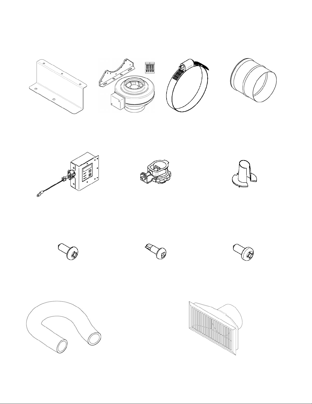
This forced air distribution kit contains the following parts:
PL53129
44142
49027
49090
1x 1x 4x 1x
SE53131
1x 1x 3x
30131 – Type A metal screw
#10 X 1/2’’ Pan Quadrex
60201
30153 – Type A self-tapping
metal screw #8 X 1/2’’ Pan
Square Tek Black
30414
30154 – Type A metal screw
#10 X 5/8’’ Square
5x 2x 1x
Other accessories required (not included):
AC01350 –
Insulated flexible
aluminized
trilaminated pipe
6’’ x 25’
2
Air register
Page 3
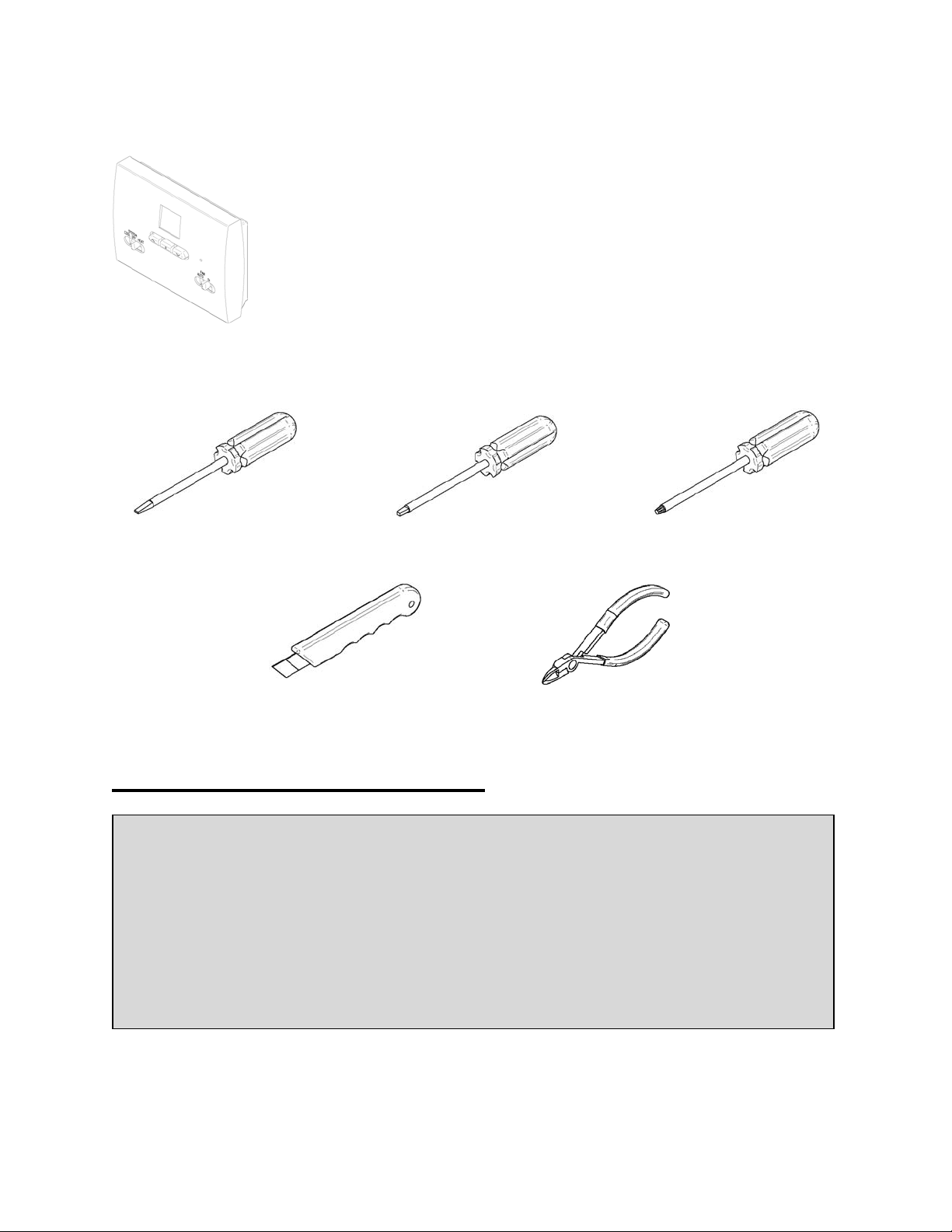
Option (not included):
AC05558
Thermostat
Tools required for installation:
Flat Screwdriver Robertson Screwdriver Phillips Screwdriver
Utility knife Cutting pliers
FORCED AIR DISTRIBUTION KIT AC01340
Warning
In Canada, the connection of the forced air kit to a furnace duct is prohibited, unless
local building codes allow it. This type of installation is allowed in the USA (UL 391
Standards). How ever, do not connect any hot air ducts to the cold air return. If
the forced air kit pipe is to be connected to a furnace hot air distribution system, a
backflow shutter (#6, not included) must be installed between the forced air kit fan
and the central system hot air duct. To favor an optimum air distribution, it is
recommended to connect the forced air kit pipe to the furnace duct using an angled
connecter oriented towards the air outlet.
If the fireplace is in a small room, the fan can be used to distribute excess heat in a
determined area of the house. A certain loss of heat is to be expected more the
duct length increase.
3
Page 4
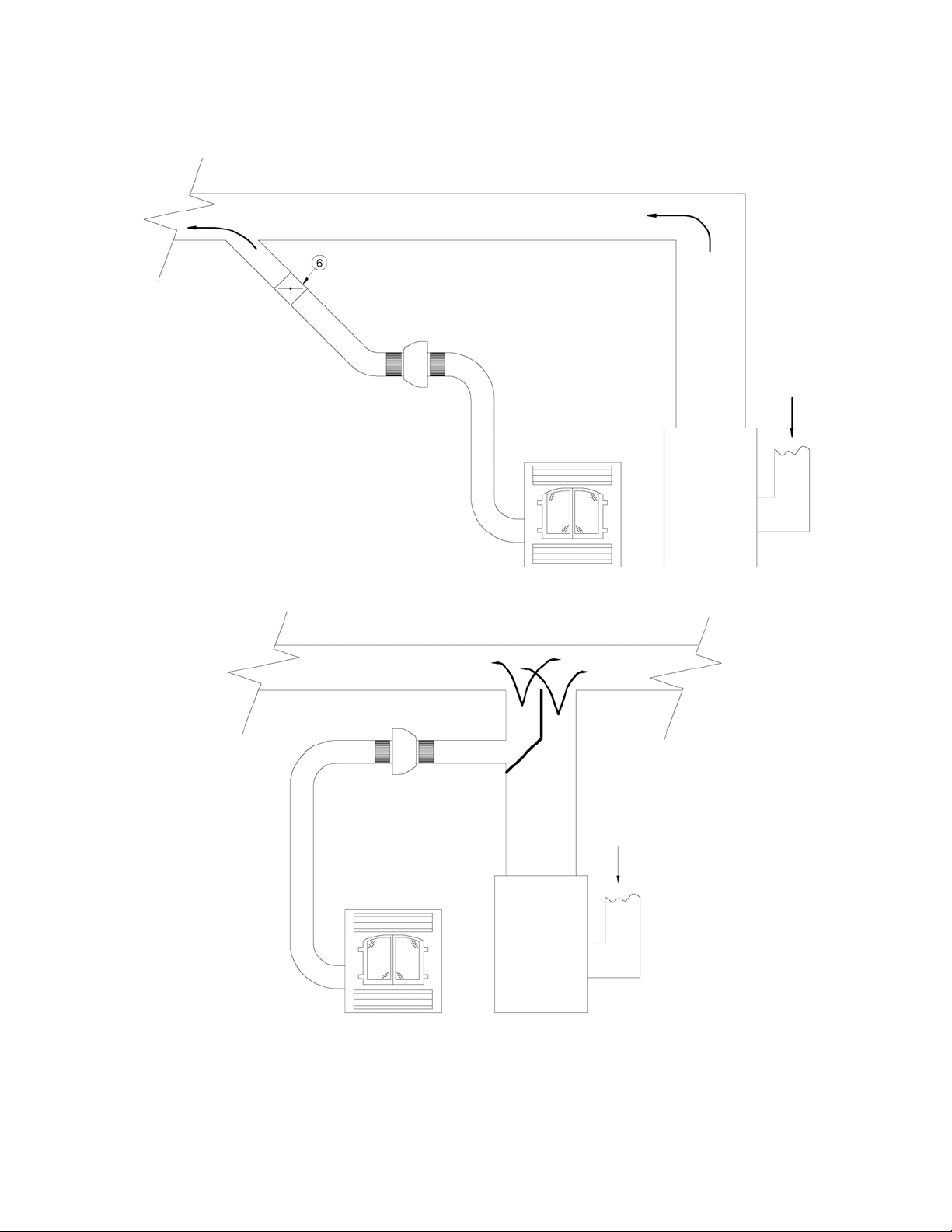
Figure 1: Forced Air Distribution Kit
4
Page 5
INSTALLATION
1
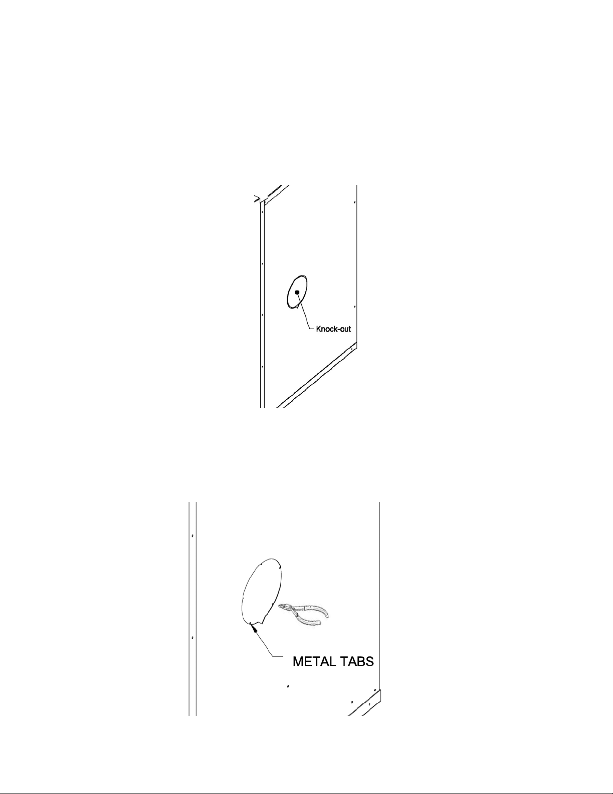
A warm air outlet can be connected on either side or rear of the unit. Remove the
knock-out on the selected side.
2
If the metal tabs did not come out with the knock-out, cut or file the remaining tabs on
the perimeter of the opening.
5
Page 6
3
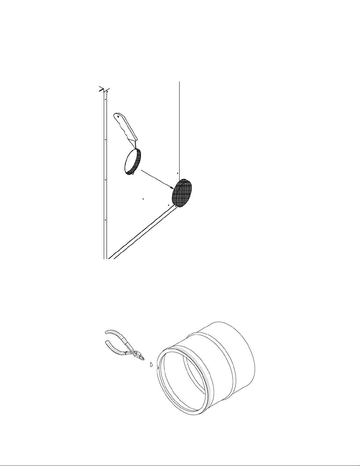
Cut out the insulation to the size of the opening.
4
Cut a notch on the perimeter of the adaptor as shown.
6
Page 7
5
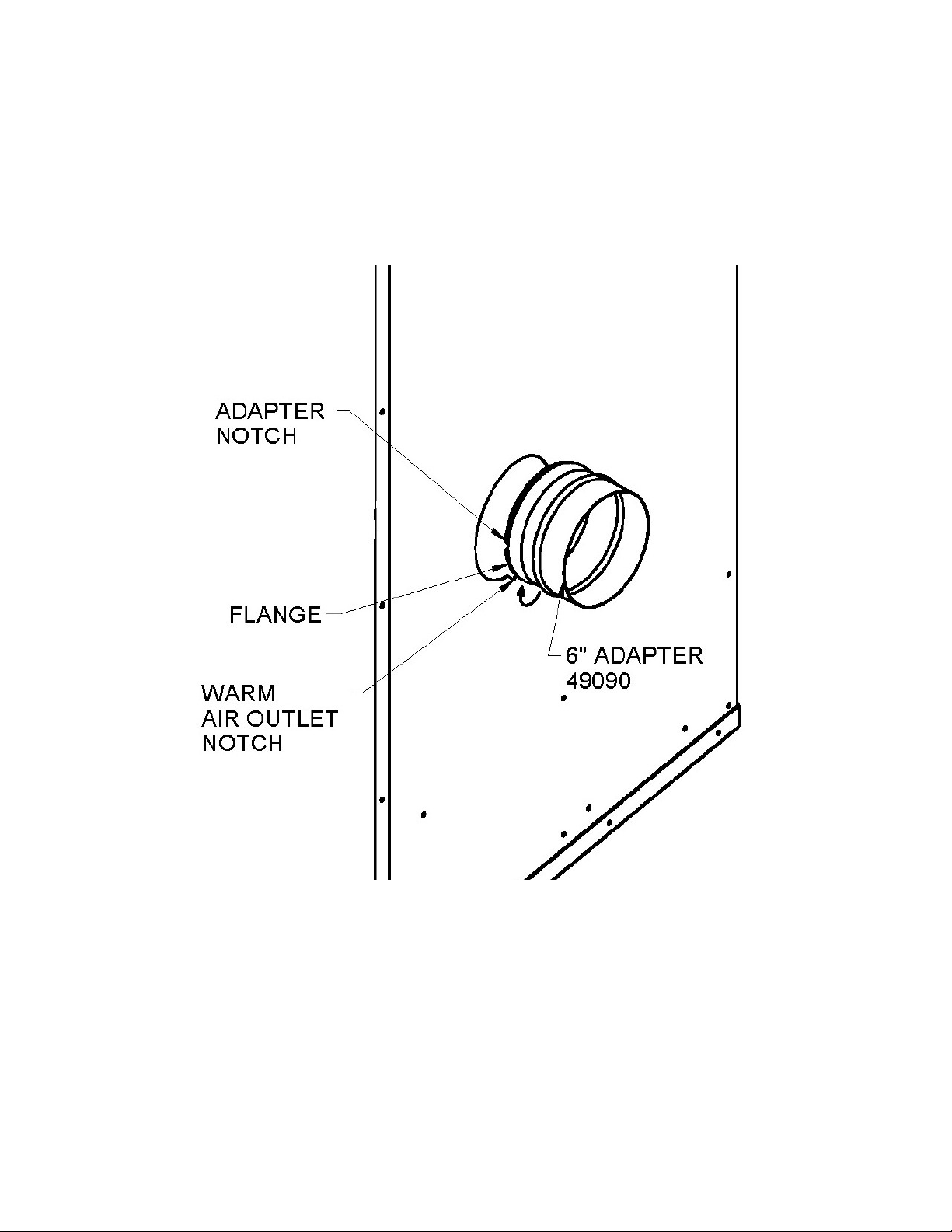
Align the adapter notch with the fireplace warm air outlet notch and turn until the flange
is fully inserted. The adapter is well in place when its flange is completely inserted and
the adapter can rotate freely.
7
Page 8
6
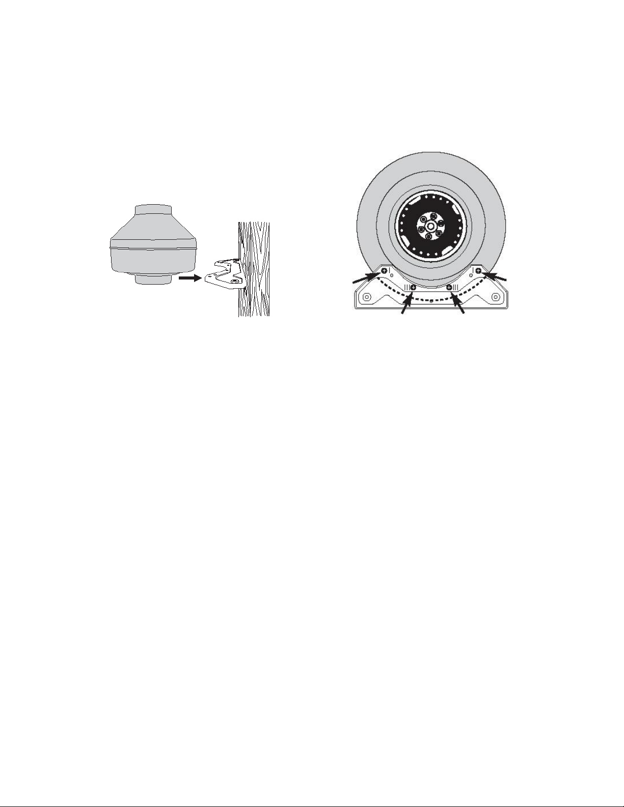
Install the heat distribution blower in a location where, you will have access for
maintenance and somewhere the fan’s noise will not be disturbing.
*Note: The heat distribution blower must be positioned at a minimum distance of 3 feet
from the fireplace and outside of its enclosure.
*Note: The length of the insulated flexible pipe between the fan and the air outlet must
be no less than 12 feet.
*Note: A minimum clearance to combustible materials of 2 inches from the heat
distribution blower is required.
*Note: The heat distribution blower can be installed horizontally, vertically or at any
angle.
8
Page 9
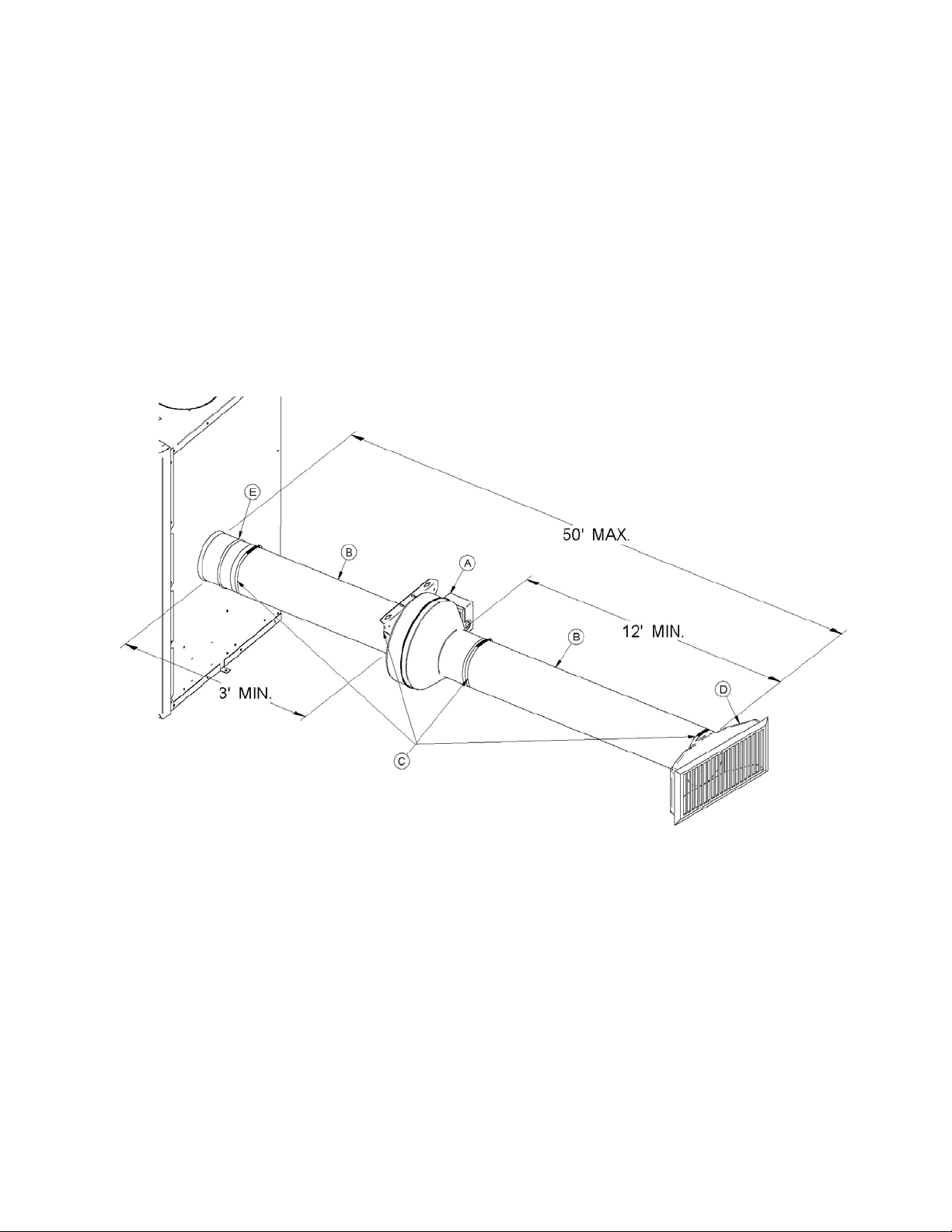
7
Connect the insulated flexible aluminized trilaminated pipe (B) to the fireplace adapter
(E), then to the inlet of the heat distribution blower (A) using two clamp collars (C). Use
the same procedure to secure the insulated flexible pipe to outlet of the heat distribution
blower (A) and to the air register (D). Although it is not mandatory, it is recommended to
use insulated flexible pipe for the entire length in order to circulate air at a sufficient
temperature through the system. To obtain optimal efficiency, a maximum run of 50
feet is recommended.
9
Page 10
PC BOARD INSTALLATION AND WIRING
Depending on the fireplace options, choose the appropriate installation instructions:
A) Fireplace equipped with a wiring terminal
B) Fireplace not equipped with a wiring terminal
*Note: Keep in mind that when installed to a decorative fireplace heat distribution blower
will take longer to reach optimum efficiency as opposed to higher rated units,
which may cause the fan to cicle.
A) Fireplace equipped with a wiring terminal
1
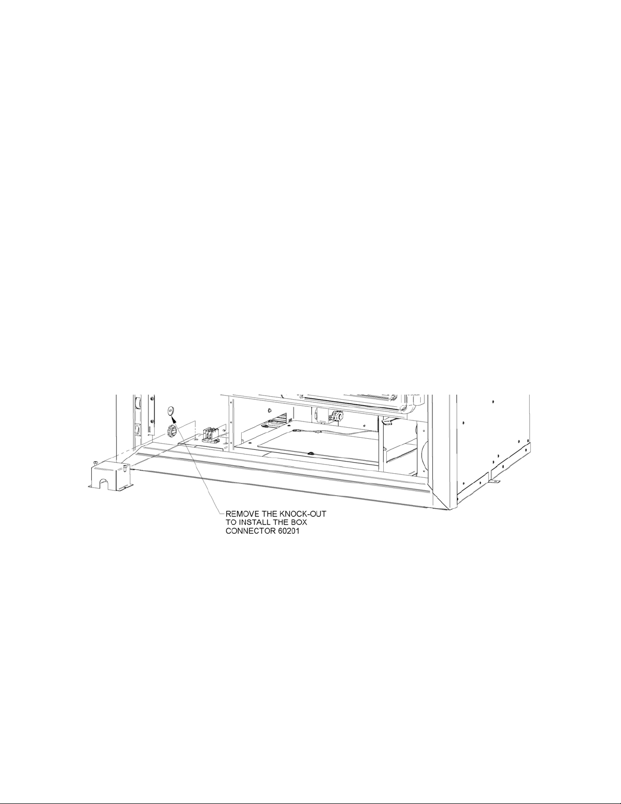
Before installing the PC board assembly, open the bottom louver of the fireplace and
remove the wire knock-out on the left hand side of the air jacket. Install the box
connector (60201) and bring in the wire coming from the blower as shown in Figure 1.
Figure 1
10
Page 11
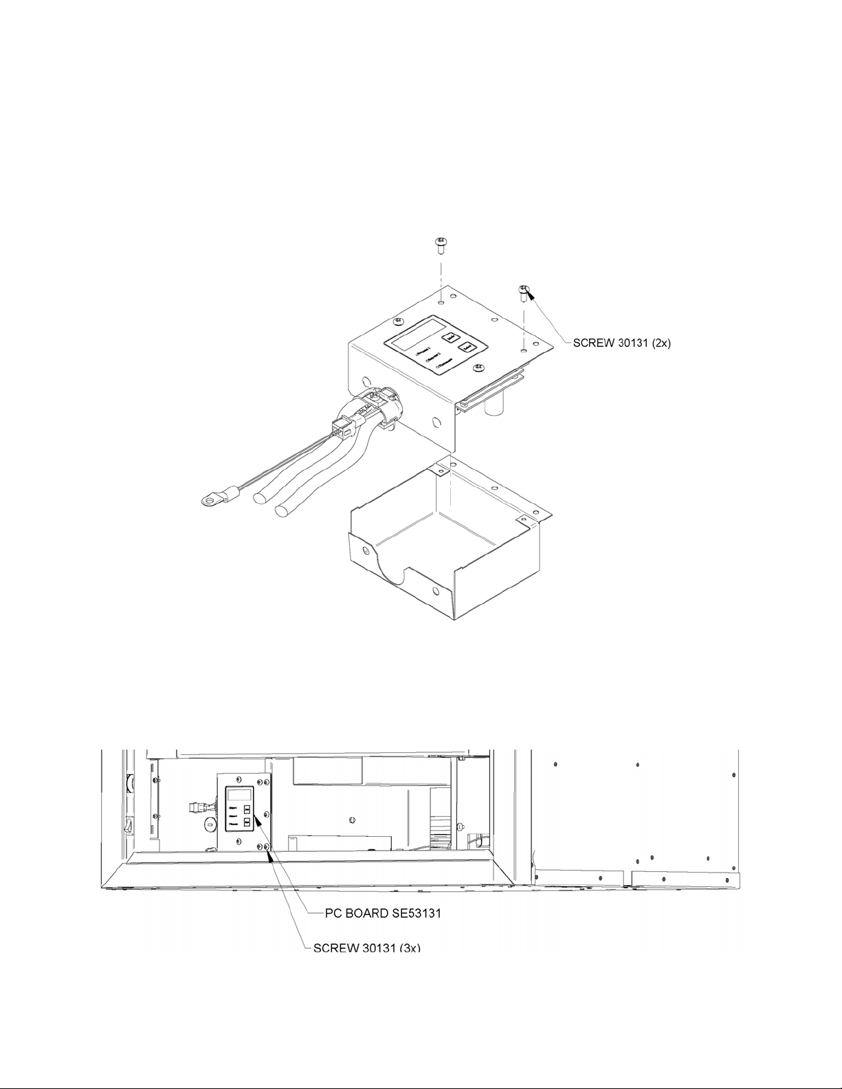
2
Connect the wires comming from the heat distribution blower and from the fireplace
terminal to the PC board (see step 5). Then install the assembly in the PC board
housing as shown in Figure 2.
Figure 2
3
Secure the PC board assembly to the outside of the firebox support (see Figure 3).
Figure 3
11
Page 12
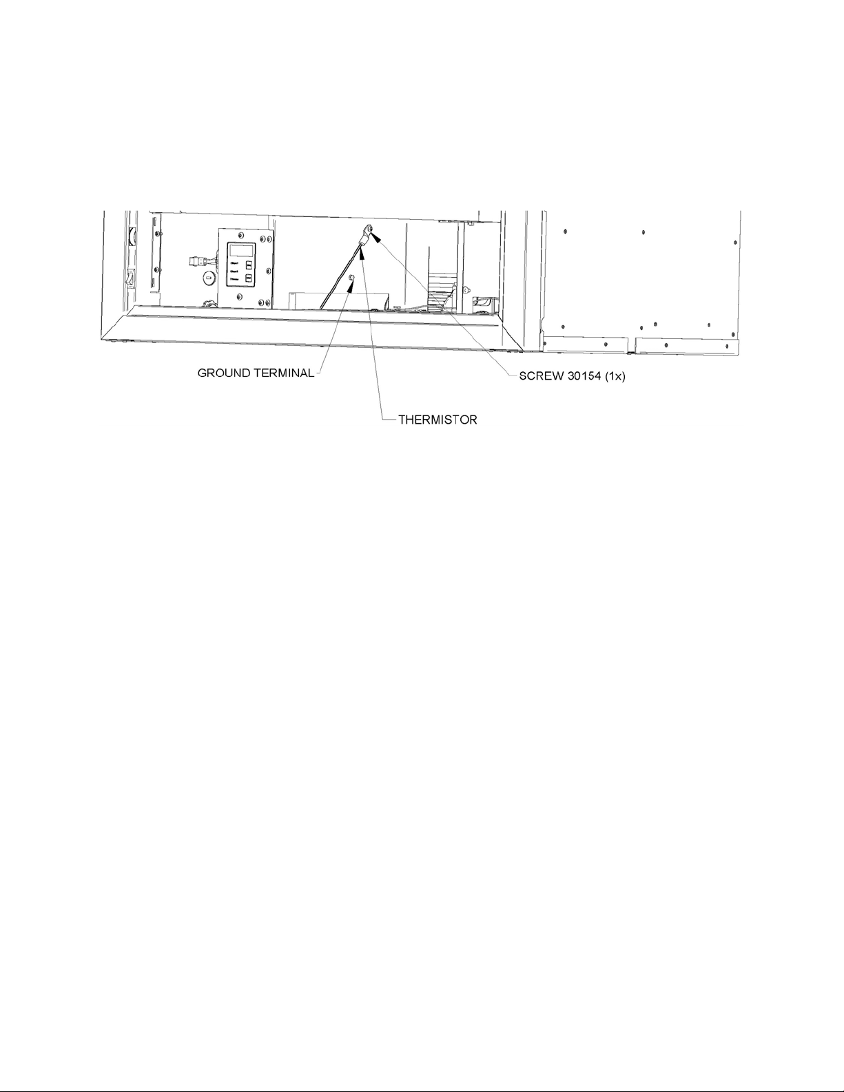
4
Finally, the ground terminal and the thermistor are to be secured to the fireplace frame
(see Figure 4).
Figure 4
5
Identify the common (white wire) on the fireplace terminal and run a white wire between
that and the ACCOM terminal of the PC board; run a black wire from the other terminal
to the ACHOT terminal of the PC board. Connect a green or nude wire from the FRAME
terminal of the PC board to the frame of the fireplace. Run an 18/3 (18 AWG) cable from
the PC board to the heat distribution blower terminal. Connect the white lead on
FANCOM in the PC board and on N at the heat distribution blower terminal. Connect
the black lead on FANHOT in the PC board and on L at the heat distribution blower
terminal. Connect the green or nude lead on FANFR in the PC board and on GROUND
at the heat distribution blower terminal (see Figure 5).
In the event that an optional thermostat (AC05558) is used, simply connect the 2 leads
coming from the thermostat to the TSTAT on the PC board (see Figure 5).
Even though it is not supplied, it is strongly recommended to install a switch on the
black lead to allow turning OFF the heat distribution blower manually before you open
the fireplace doors. If the blower is running, the smoke could be drawn out of the
fireplace instead of up the chimney and sparks may be drawn into the insulated
flexible pipe of the forced air kit. Note that this switch will not turn the heat distribution
blower ON unless the fireplace is hot enough (See Figure 6).
12
Page 13
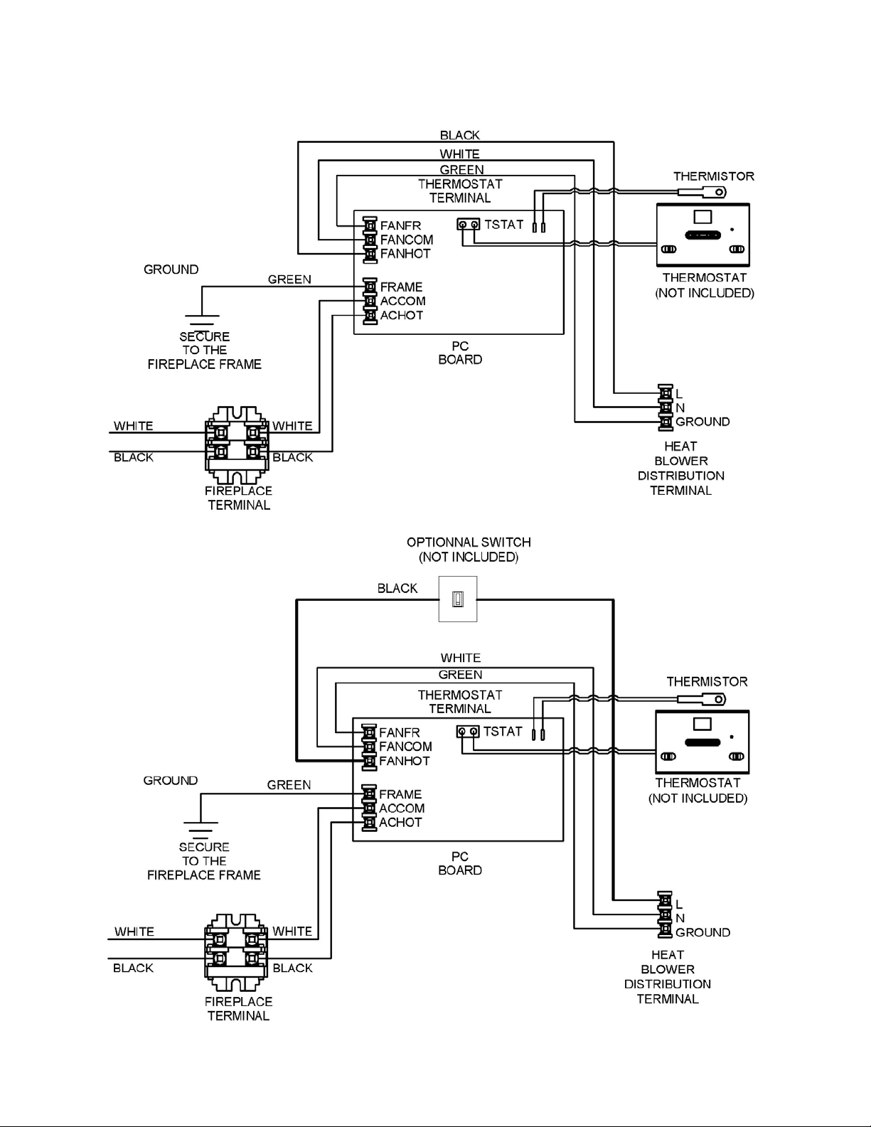
Figure 5
Figure 6
13
Page 14
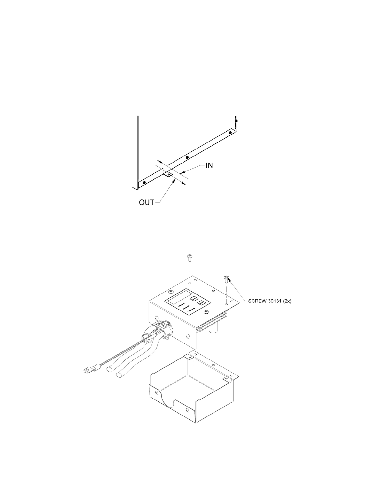
B) Fireplace not equipped with a wiring terminal
1
Determine a location on the side of your fireplace where you can drill a hole to run your
electrical wiring, and in close proximity of any electrical devise if any.
2
Wire the PC board (see step 5), then install the assembly in the housing as shown
below.
14
Page 15
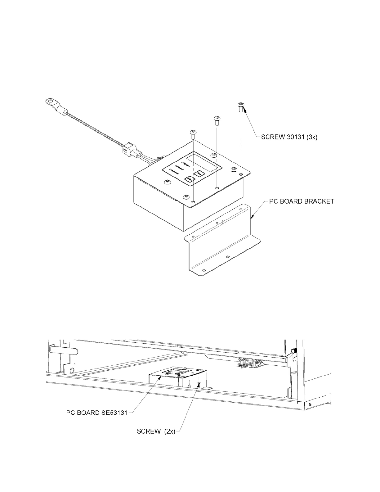
3
Secure the PC board assembly to the PC board bracket (see Figure 6).
Figure 6
4
Secure the PC board bracket to the floor of the fireplace frame (see Figure 7).
Figure 7
15
Page 16
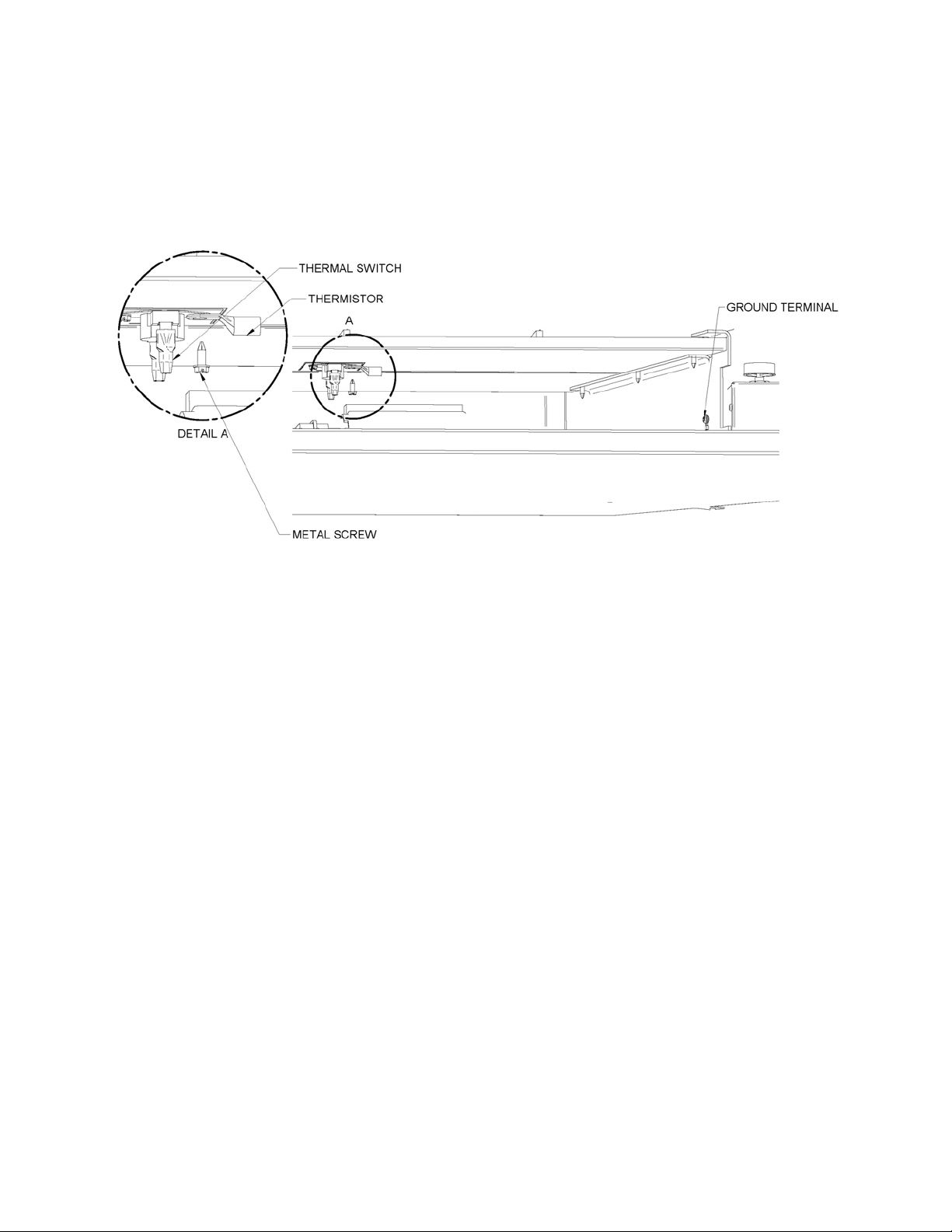
5
Finally, the ground terminal is to be secured to the fireplace frame and the thermistor to
the fireplace using the same metal screw already securing the thermal switch (see
Figure 8).
Figure 8
6
Connect a white wire to the ACCOM terminal of the PC board. Connect a black wire to
the ACHOT terminal of the PC board. Connect a green or nude wire from the FRAME
terminal of the PC board to the frame of the fireplace. Run an 18/3 (18 AWG) cable from
the PC board to the heat distribution blower terminal. Connect the white lead on
FANCOM in the PC board and on N at the heat distribution blower terminal. Connect
the black lead on FANHOT in the PC board and on L at the heat distribution blower
terminal. Connect the green or nude lead on FANFR in the PC board and on GROUND
at the heat distribution blower terminal (see Figure 9).
In the event that an optional thermostat (AC05558) is used, simply connect the 2 leads
coming from the thermostat to the TSTAT on the PC board (see Figure 9).
Even though it is not supplied, it is strongly recommended to install a switch on the
black lead to allow turning OFF the heat distribution blower manually before you open
the fireplace doors. If the blower is running, the smoke could be drawn out of the
fireplace instead of up the chimney and sparks may be drawn into the insulated
flexible pipe of the forced air kit. Note that this switch will not turn the heat distribution
blower ON unless the fireplace is hot enough (See Figure 10).
16
Page 17
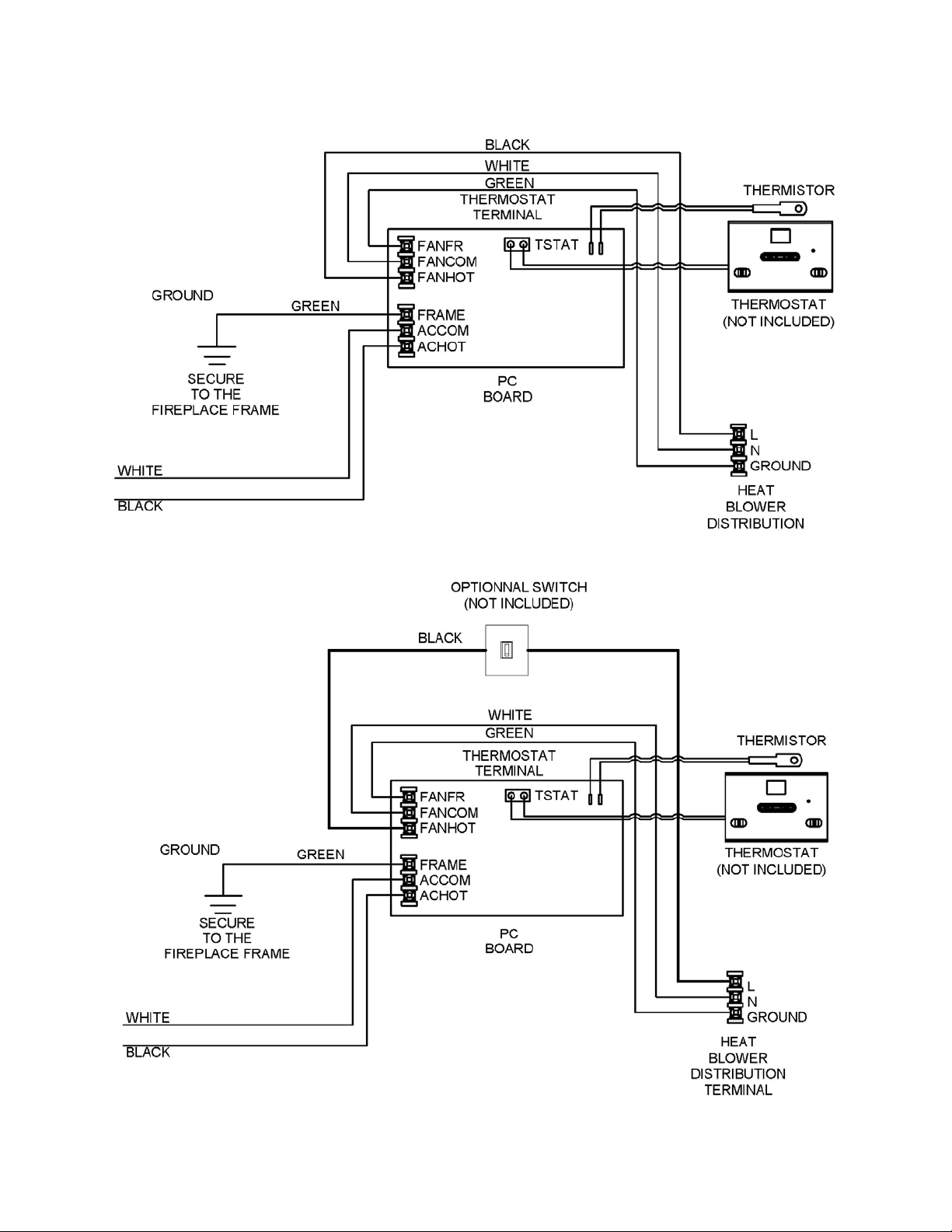
Figure 9
Figure 10
17
Page 18
PC BOARD OPERATION & CONFIGURATION
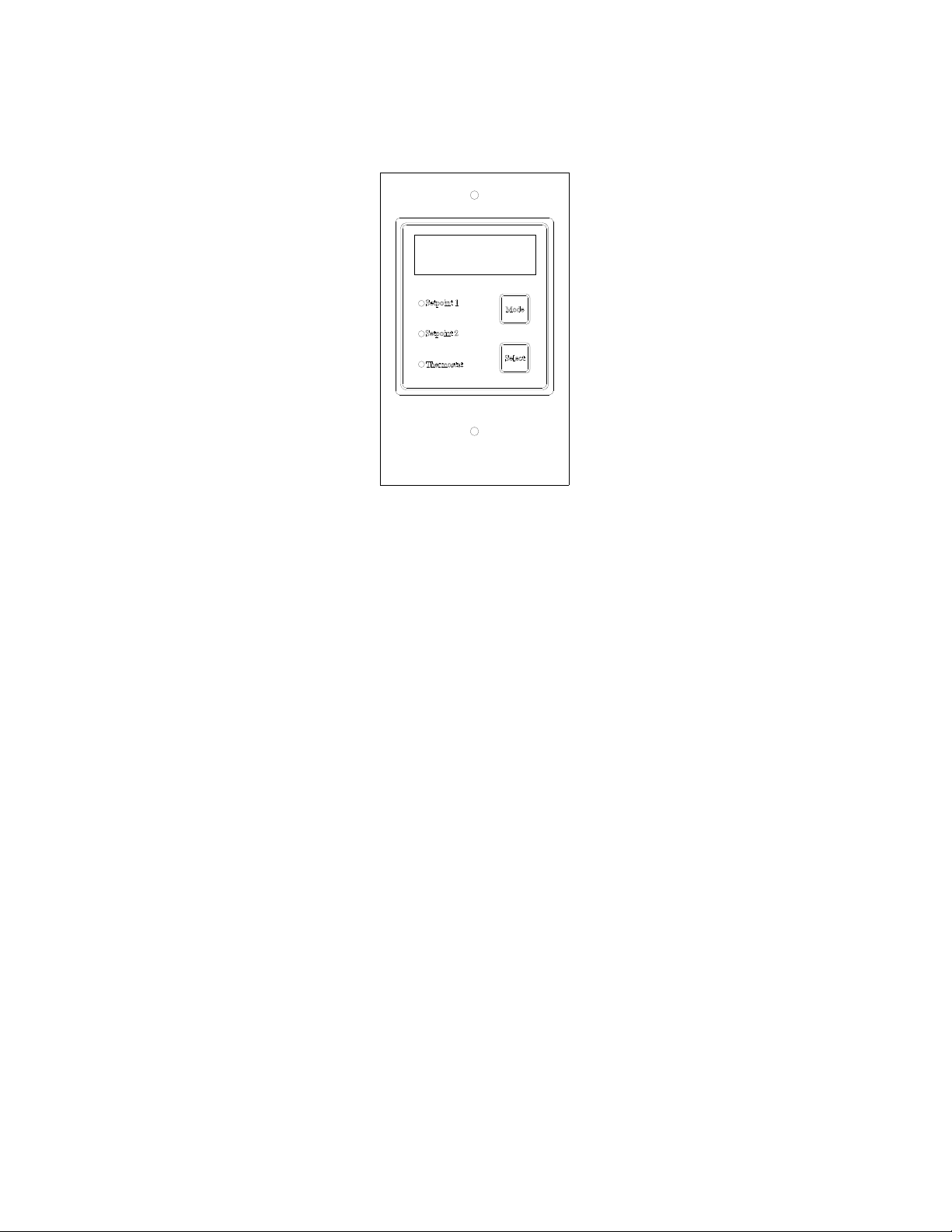
Press the ‘’Mode’’ button until the desired option light turns on. Press the ‘’select’’
button to save that option. Available configuration options are indicated on the
display located on the top of the control.
"Setpoint 1" is the temperature (in Fahrenheit) at which the heat distribution
blower will kick in on slower speed. You may choose between "None", "110°F",
"125°F" or "140°F". If "None" is selected, the heat distribution blower will not kick
in until "Setpoint 2" temperature is reached.
"Setpoint 2" is the temperature (in Fahrenheit) at which the heat distribution
blower will kick in on fast speed. "Setpoint 2", will determine at what temperature
(in Fahrenheit) the heat distribution blower will switch from low speed to high
speed. Options for "Setpoint 2" are "175°F", "190°F" or "205°F".
"Thermostat" allows choosing the "Cool" or "Heat" option depending where your
thermostat is located. When the thermostat is located in the remote area you
want to heat, the thermostat will be set in ‘’Heat’’ and the heat distribution blower
will be activated when the temperature drops bellow the thermostat setpoint.
When the thermostat is located in the same room as the fireplace, the thermostat
will be set in ‘’Cool’’ so the heat distribution blower will kick in when the
temperature in that room rises above the thermostat setpoint.
Note: When manual mode is to be used, thermostat option on the PC board must be
set on ‘’Cool’’.
Note: Configuration must be repeated after a power failure.
18
Page 19

Notes
19
Page 20

Stove Builder International inc.
250, rue de Copenhague
Saint-Augustin-de-Desmaures Quebec, Canada
G3A 2H3
20
 Loading...