

Orion VII EPA10 Owner's Manual

OPERATOR’S MANUAL
ACADEMY EXPRESS HYBRID 1368A
Printed: December 21, 2010
ORION VII HYBRID VEHICLE

CONTACT INFORMATION:
Daimler Buses North America
350 Hazelhurst Road
Mississauga, Ont ari o
Canada L5J 4T8
Telephone (905) 403-1111
Daimler Buses North America
165 Base Road, PO Box 748
Oriskany, New York
USA 13424
Telephone (315) 223-5100
© 2010 DAIMLER BUSES NORTH AMERICA

Table of Contents
INTRODUCTION ...............................................................................................................................1
GENERAL ......................................................................................................................................... 2
HYBRID ELECTRIC VEHICLE (H.E.V.) SAFETY INFORMATION ...................... ...... ..... ...... ...... ..... .3
Hybrid Electric Vehicle Propulsion System ................................................................................ 3
High Voltage Hazards ................................................................................................................3
OPERATOR’S COMPARTMENT ......................................................................................................4
FRONT INSTRUMENT PANEL .........................................................................................................9
WARNING LIGHTS AND INDICATORS .........................................................................................13
DRIVER’S SIDE CONTROL PANEL ...............................................................................................19
MASTER SWITCH ..........................................................................................................................25
Engine Stop Position ................................................................................................................25
Day Run Position .....................................................................................................................25
Night Run Position ...................................................................................................................25
Park Position ............................................................................................................................25
DESTINATION SIGNS ....................................................................................................................26
Electronic Destination Sign .......................................... ..... ...... ..... ...... ......................................26
Operator’s Display and Keyboard (ODK) .................................................................................26
Destination Sign Dimming Feature .......................................................................................... 28
DRIVER’S SEAT .............................................................................................................................29
USSC™ Q91 Driver’s Seat ......................................................................................................30
Driver’s Seat Belt .....................................................................................................................31
AIR BRAKE SYSTEM OPERATION ...............................................................................................32
Loss of Air Pressure .................................................................................................................32
Wet Weather Operation ...........................................................................................................33
Emergency/Parking Brake Control Valve ................................................................................. 33
Brake Interlock ......................................................................................................................... 34
Page 1

Table of Contents
Rear Axle Brakes Safety Circuit ........................................ ...... ..... ............................................34
Anti-Lock Braking System (ABS) .............................................................................................35
ABS Warning Light ...................................................................................................................35
ENGINE OPERATION ....................................................................................................................36
Pre Start-Up Inspection ............................................................................................................ 36
Starting an Electronically Controlled Engine ............................................................................ 36
Engine Warm Up ...................................................................................................................... 37
Operating the Engine ........................................................ ...... ..... ...... ......................................37
High Idle ................................................................................................................................... 37
Stopping the Engine .................................................................................................................38
Starting Engine From Rear Control Panel ...............................................................................38
Stopping Engine From Rear Control Panel ..............................................................................39
Engine Protection System - Electronically Controlled Engines (Cummins ISB™) ................... 39
B.A.E.™ HYBRID PROPULSION SYSTEM ....................................................................................41
Hybrid Electric Vehicle (HEV) Propulsion System Operation ................................................... 41
Propulsion Control System (PCS) ............................................................................................41
Alternating Current Traction Generator (ACTG) ......................................................................41
Alternating Current Traction Motor (ACTM) .............................................................................42
Motor Speed Warning Indicator ...............................................................................................42
Electric Alternator System (EAS) .............................................................................................42
Propulsion Control System (Emergency) Override Switch ....................................................... 43
Throttle and Brake Pedals .......................................................................................................43
Gear Range Selector Position .................................................................................................43
Stop HEV Indicator ..................................................................................................................44
DRIVER’S PRE-SERVICE INSPECTION ....................................................................................... 45
Driver Walk Around Test ..........................................................................................................45
Page 2

Table of Contents
Exterior Inspection ...................................................................................................................45
Interior Inspection ....................................................................................................................45
LIGHTING AND ELECTRICAL ........................................................................................................47
Lighting Operation .................................................................................................................... 47
Interior Lighting ........................................................................................................................ 47
Exterior Lighting ....................................................................................................................... 48
Batteries ...................................................................................................................................49
Disconnection of Electrical System .......................................................................................... 49
HEATING, AIR CONDITIONING, AND VENTILATION ...................................................................51
Front Heat/Defrost Blower Switch ................................ ..... ...... .................................................51
Climate Control System ......................................... ...... ............................................................52
Climate Control System Switch ................................................................................................ 52
Driver’s Booster Blower Switch ................................................................................................52
Fresh Air Ventilation .................................................................................................................53
Driver’s Fan .............................................................................................................. ................53
IntelligAIRE™ Climate Control System ....................................................................................54
PASSENGER ENTRANCE AND EXIT DOORS .............................................................................56
Accelerator Interlock ................................... ..... ...... ...... ..... .......................................................56
Door System Operation ...........................................................................................................56
Pull Cord Stop Request ................................... ...... ...... ............................................................57
Speed Sensing Interlock ..........................................................................................................57
Malfunction in Opening and Closing Front Door ......................................................................57
Door Master Switch ..................................................................................................................58
Malfunction in Opening and Closing Rear Doors .....................................................................58
External Front Door Access Switch .........................................................................................59
EMERGENCY ESCAPE EXITS ......................................................................................................60
Page 3

Table of Contents
Push Out Egress Windows ......................................................................................................60
Rear Roof Hatch ...................................................................................................................... 60
KNEELING SYSTEM .......................................................... ..... ...... ..... ...... ......................................61
Kneeling System Operating Procedure ....................................................................................61
WHEELCHAIR RAMP SYSTEM .....................................................................................................63
Ramp Malfunction .................................................. ...... ..... ...... ..... ............................................63
Operation .................................................................................................................................63
WHEELCHAIR RESTRAINT SYSTEM ...........................................................................................65
Mobility Device Securement Instructions .................................................................................65
ENGINE COOLING SYSTEM ......................................................................................................... 67
Checking and Replenishing Engine Coolant ............................................................................67
High Coolant Temperature .......................................................................................................68
Low Engine Coolant Level .......................................................................................................68
Modular Traction System (MTS) Coolant ................................................................................. 69
AMEREX™ FIRE SUPPRESSION SYSTEM ..................................................................................70
Fire Suppression System .........................................................................................................71
Automatic Operation ................................................................................................................72
Manual Operation ....................................................................................................................72
EXTERIOR COMPARTMENT AND SERVICE ACCESS DOORS .................................................74
GENERAL DATA AND TECHNICAL INFORMATION .................................................................... 77
Reporting Safety Defects .........................................................................................................78
Page 4
Introduction
INTRODUCTION
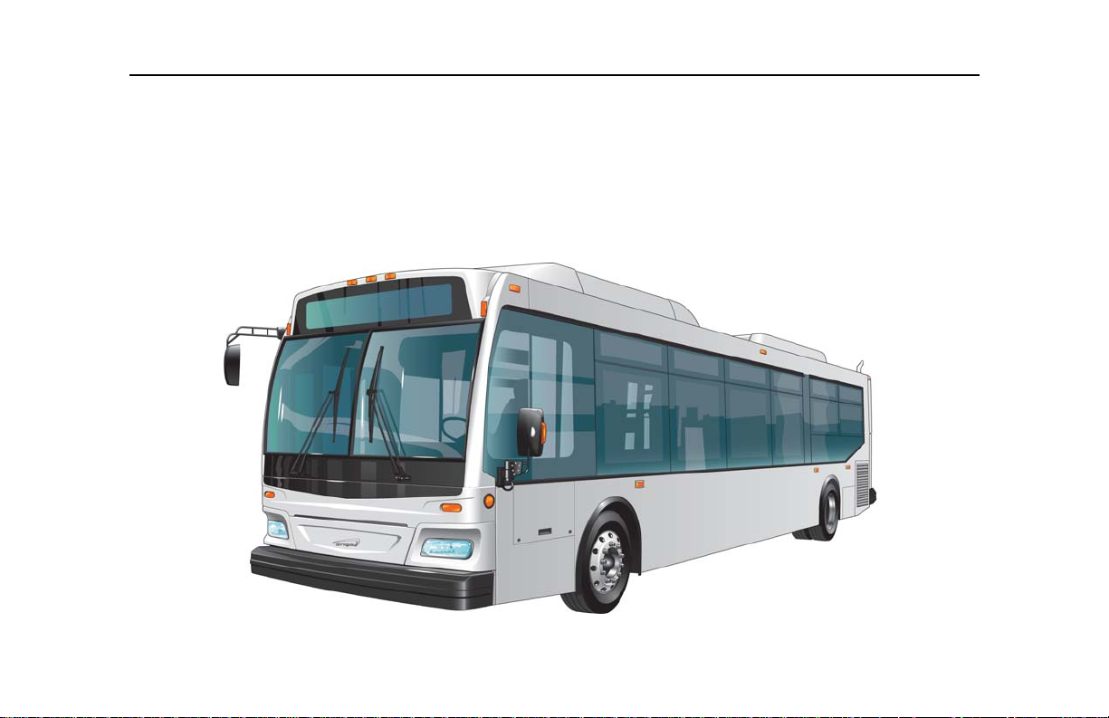
This manual describes the operating features and safety equipment of the Orion VII EPA10 Hybrid Vehicle. All
personnel involved in the operation of this vehicle should read this manual before providing any public service.
For additional information or assistance, refer to the contact information located at the back of this manual.
Page 1

General
GENERAL
The Orion VII EPA10 hybrid vehicle incorporates specia lly des igned features that provi de transp orta tion to the mobili ty
impaired and physically challenged. It is the operator’s responsibility to assist each passenger in boarding, seating,
attaching and securing restraining belts, and to provide assistance when leaving the vehicle.
Special features of the vehicle fulfill passenger needs in the following areas:
• Kneeling and wheelchair ramp
features allow coach floor to
street level access for the
wheelchair bound individual.
• Restraining belts and
securement devices are
located at all wheelchair
positions.
• Pull cords and push buttons
alert the operator of the NEXT
STOP request, are easily
accessible.
Page 2

Hybrid Electric Vehicle (H.E.V.) Safety Information
DANGER
DANGER
DANGER
HYBRID ELECTRIC VEHICLE (H.E.V.) SAFETY INFORMATION
Hybrid Electric Vehicle Propulsion System
Due to extremely high voltage
supplied by the energy storage
system (ESS), the propulsion
system contains a battery isolator
switch which allows the operator to
cut off propulsion system power in
special circumstances such as a
vehicle accident. This switch is
located in the curbside battery
compartment.
of Electrical System” on page 49.
See “Disconnection
High Voltage Hazards
Use extreme caution if any work
has to be performed on the
engine while it is running. High
voltage is present at the
generator terminals, traction
motor terminals, and all high
voltage cabling connecting the
generator and traction motor to
the Propulsion Control System
(PCS).
Use of the Battery Isolator
Switch is mandatory during
propulsion system maintenance.
If the vehicle was running just
prior to conducting
main99tenance, allow four
minutes for propulsion system
components to discharge
electricity before proceeding.
Even with the Battery Isolator
Switch in the OFF position, the
traction battery system remains
a severe shock hazard because
the battery modules themselves
are not disconnected by the use
of this switch. Always use
extreme caution when working
around the rooftop tub.
Although the operator would rarely
have access to any of the
propulsion system components,
he/she must be made aware of the
potential hazards.
Should a problem exist which
requires attention to the propulsion
system, the matter should
immediately be brought to the
attention of qualified service
personnel. For further information
on the HEV system, refer to BAE
Systems™ maintenance manual.
Page 3
Operator’s C ompartment
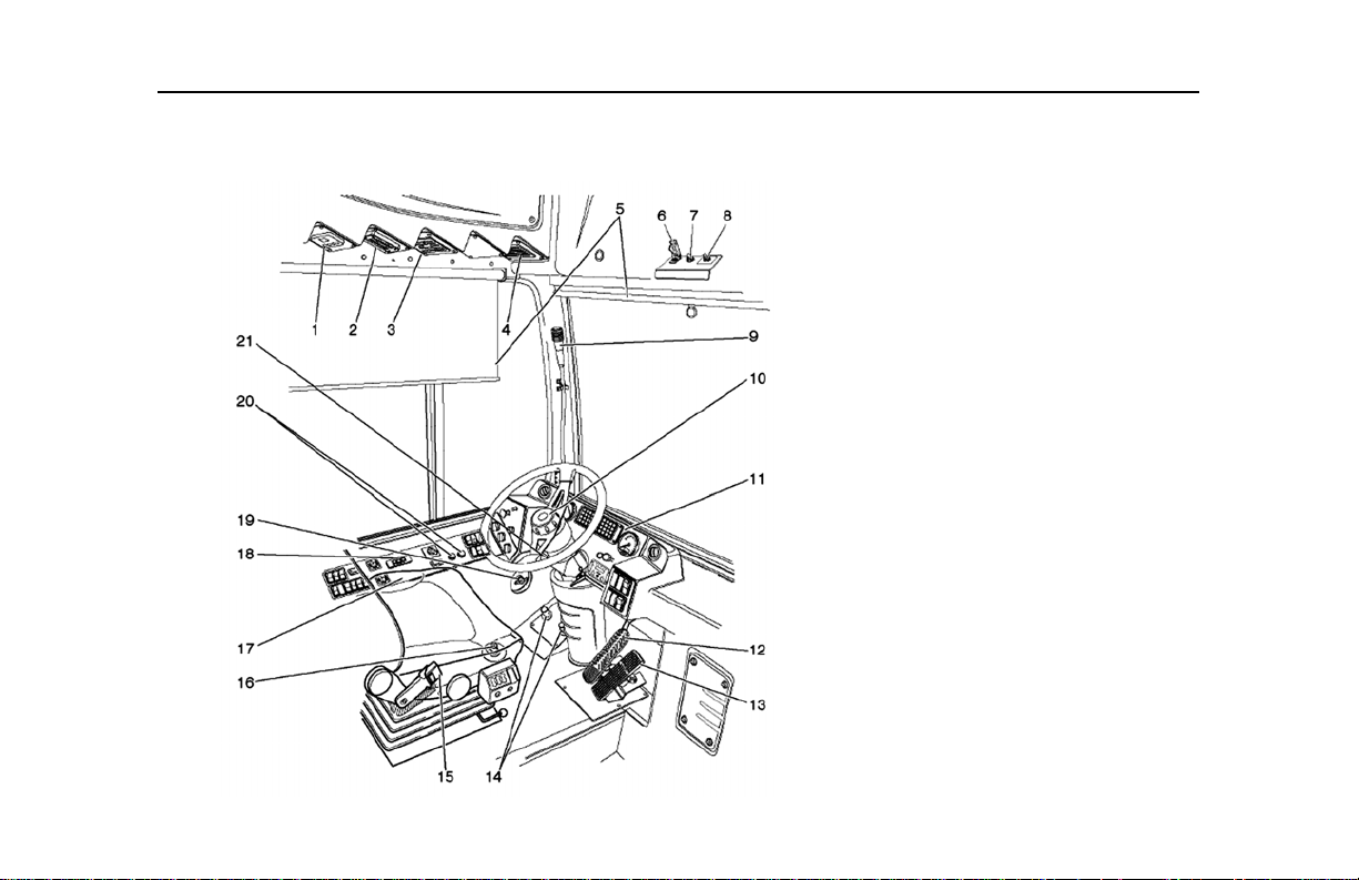
OPERATOR’S COMPARTMENT
LEGEND
1. IntelligAIRE III™ Display Panel
2. Passenger Stop Request Chime
Unit
3. Destination Sign Keypad
4. Driver’s Booster Blower Vent
5. Driver’s Pull Down Sunvisors
6. Door Master Switch
7. Exhaust Regeneration Override
Switch
8. Regenerative Braking Switch
9. Gooseneck Microphone
10. Horn Button
11. Front Instrument Panel
12. Brake Pedal
13. Accelerator Pedal
14. Directional Signal Foot Control
Switches
15. Driver’s Seat
16. Headlight Dimmer Foot Control
Switch
17. Side Control Panel
Page 4

Operator’s C ompartment
CAUTION !
LEGEND
18. Alternating Current Traction
Motor (ACTM) Gear Selector
19. Door Emergency Release Valve
20. Driver’s Door Control Push
Buttons
21. Tilt/Telescopic Steering Column
Lever
The following features and special
equipment are used for normal
vehicle operation.
1. IntelligAIRE™ Display Panel
This display panel includes 4
touch keys, a 3 digi t display and
various display indicators. The
panel provides outside and
inside temperature readouts
and setpoint adjustments only.
See “IntelligAIRE™ Climate
Control System” on page 54.
2. Passenger Stop Request
Chime Unit
A single chime will be heard
from this unit when a
passenger, requesting a stop,
activates the touch tape. A
double chime notifies the
operator that a wheelc hair
passenger is requesting a stop.
3. Destination Sign Keypad
This keypad is used for
destination sign message
selection and programming.
See “Operator’s Display and
Keyboard (ODK)” on page 26.
4. Driver’s Booster Blower Vent
An auxiliary blower and vent
located inside the overhead
panel, above the operato r’s
roadside window, provides the
operator’s area with additional
climate control.
See “Fresh Air
Ventilation” on page 53.
5. Driver’s Pull Down Sunvisors
These adjustable pull down
mechanisms, loca ted above the
operator windshield and
operator’s side window,
prevents eye exposure to
sunlight. A scissor type
reinforcement retain s the
shades rigidity a nd prevents the
shade from excessive swaying.
6. Door Master Switch
Apply the parking or service
brakes before removing the door
master switch from its normally
guarded position to prevent the
vehicle from rolling.
The Door Master switch is a
guarded two position (NORM,
DISABLE) toggle switch used
to override a door malfunction
that is activating the door
interlock system a nd preventing
the service brakes and
accelerator interlocks from
releasing.
7. Exhaust Regeneration
Override Switch
The Exhaust Regeneration
Override swi tch is used in
situations where the front dash
HEST lamp is illuminated and
Page 5

Operator’s C ompartment
NOTE
the vehicles exhaust outlet is
near an area that could be
effected by high temperatures.
8. Regenerative Braking
Disable Switch
This two position (ON, OFF)
toggle switch enables the
operator to deactivate
regenerative braking in the
hybrid propulsion system. The
Regenerative disable switch
should be used only during
slippery, hazardous road
conditions.
9. Gooseneck Microphone
This microphone allows for
flexible operation of the
vehicles’ public address
system. A switch on the
microphone allows the operator
to activate the Public Address
system.
10. Horn Button
Pressing the disk in the center
of the steering wheel activates
two electrical horns.
11. Front Instrument Panel
This panel, located in front of
the operator, contains gauges,
indicator lights , and contro ls for
operating and monitoring
various vehicle systems. See
“Front Instrument Panel” on
page 9.
12. Brake Pedal
A "creep forward" mode is
present in all EPA10 hybrid
vehicles; as a result, the vehicle
will creep forward when the gear
range selector is in the D (drive)
position and the brake pedal is
released.
This foot-operated treadle
valve, located on the
compartment floor to the
immediate right of the steering
wheel, applies the vehicle
service brakes.
13. Accelerator Pedal
This foot operated pedal,
remotely controls the engine
fuel governor control, which in
turn controls the speed of the
vehicle.
This pedal is located on the
compartment floor to the right
of the brake pedal.
14. Directional Signal Foot
Control Switches
These two foot switches,
located on the floor to the lef t of
the steering wheel, ac tiv ate the
left and right turn signal lights.
Each switch must be pres se d
and held for the duration of the
signal.
15. Driver's Seat
The driver’s seat is equipped
with comfort options to
accommodate most operators.
See “Driver’s Seat” on
page 29.
Page 6

Operator’s C ompartment
WARNING
16. Headlight Dimmer Foot
Control Switch
This foot switch, when
activated, selects the headlight
high or low beam settings.
17. Side Control Panel
This panel, located on the left
hand side of the operator,
contains controls and switches
necessary for various vehicle
systems operations.
These systems include climate
control, front and rear door
control, master control of the
vehicle electrical system,
lighting, etc. See “D river’s
Side Control Panel” on
page 19.
18. Alternating Current Traction
Motor (ACTM) Gear Selector
Drive modes available on this
selector are Drive (D), Neutral
(N), and Reverse (R).
“Gear Range Selector
Position” on page 43.
See
19. Door Emergency Release
Valve
This rotary air valve overrides
the air system to allow front
doors to be opened manually.
See “Malfunction in Opening
and Closing Front Door” on
page 57.
20. Driver’s Door Control Push
Buttons
The rear and front door
controller push buttons allow
the operator to activate the
front and/or rear door s. Press
once to open and press again
to close the doors.
21. Tilt/Telescopic Steering
Column Lever
Stop the vehicle and apply the
parking brake before adjusting
the steering column. Failure to
do so could result in loss of
vehicle control, causing perso nal
injury and/or vehicle damage.
The steering column is
equipped with adjustment
features that accom modate the
size and height of most
operators. Tilt and height
features are adjusted using a
lever on the left hand side of
the steering column.
To adjust the tilt angle:
a. Pull back on the lever.
b. Grasp the steering wheel
and adjust the angl e forward
and aft until the desired
angle is reached.
Page 7

Operator’s C ompartment
c. Push down slightly on the
lever and gently articulate
the wheel until the column
locks in place.
Page 8
FRONT INSTRUMENT PANEL
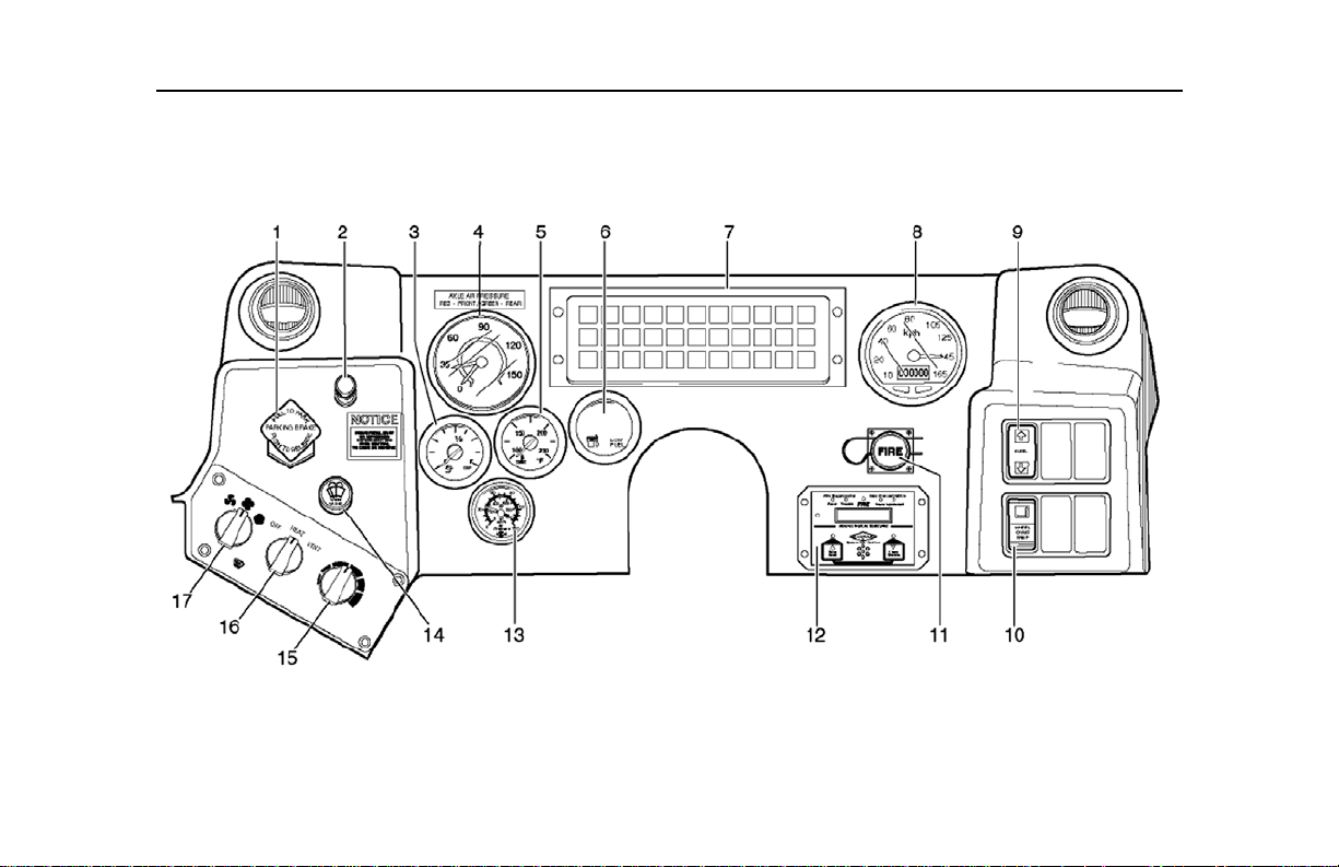
Front Instrument Panel
Page 9

Front Instrument Panel
LEGEND
1. Parking/Emergency Brake
Control
2. Wiper Control Lamp
3. Diesel Emission Fluid (DEF)
Gauge
4. Air System Pressure Gauge
5. Engine Coolant Tem perat ure
Gauge
6. Diesel Fuel Gauge
7. LED Warning Lights and Indicator
Panel
8. Speedometer/Odometer Gauge
9. Kneeling System Switch
10. Wheelchair Ramp Switch
11. Manual Fire Suppression Button
12. Automatic Fire Suppression
System (AFSS) Display Panel
13. Accessory Tank Air Pressure
Gauge
14. Windshield Wiper/Washer Control
Valve
15. Driver’s Temperature Control
16. Driver’s Heat/Ventilation Control
17. Driver’s Heater/Defroster Control
The front instrument panel is a
collection of gauges, controls, and
warning indicators used to operate
and monitor various vehicle
systems.
1. Parking/Emergency Brake
Control
This Push/Pull valv e applies the
rear wheel spring brakes when
parking. It may also be used to
stop the vehicle in an
emergency situation.
PULL on the valve knob to
apply brakes, and PUSH to
release br akes.
See
“Emergency/Parking Brake
Control Valve” on page 33.
2. Wiper Control Lamp
This fixture illuminates the
wiper controls.
3. Diesel Emission Fluid (DEF)
Gauge
This gauge measures the
amount of DEF in the 10.6
gallon reservoir tank. Diesel
emission fluid is mixed with hot
exhaust, resulting in an
alteration of the chemical
composition of the ex haust to
make it EPA10 compliant.
A solid red light indicates an
initial warning level of 16.6%;
under such conditions,
removed the vehicle from
service immediately.
A flashing red light indicates a
critical warning level of 11%;
under such conditions,
immediately move the vehicle
to a safe location and shutdow n
the engine.
4. Air System Pressure Gauge
This dual indicator gauge
monitors brake circuit air
pressure for both primary and
secondary air circuits.
Normal air system pressure
should not register below
70 psi.
The spring brakes w ill gradually
apply automatically if pressure
Page 10

Front Instrument Panel
NOTE
is lost, and will be fully app lied if
pressure drops to 40 psi.
“Air Brake System
Operation” on page 32.
5. Engine Coolant Temperature
Gauge
This gauge registers the engine
coolant temperature. The
gauge is designed to register a
temperature range from 100° 260°F (38° - 127°C). The
normal operating temperature
is between 180° - 200°F (82° 93°C). If the temperature
continues to rise above this
range, the excessive high
temperature will trigger an
audible alarm and il luminate the
CHECK ENGINE indicator on
the front instrument pa nel. If the
engine temperature continues
to rise above 212°F (100°C),
the engine control unit (ECU)
will commence shutdown
sequence.
See
6. Diesel Fuel Gauge
This gauge indicator monitors
the amount of diesel fuel in the
125 gallon fuel tank.
Approximately 18 gallons of
fuel remains in the fuel tank
when the low fuel light on the
gauge illuminates. An EMPTY
reading indicates 11.7 gallons
of fuel remaining in the fuel
tank.
The vehicle will run out of fuel
with 5.37 gallons remaining in
the fuel tank.
7. LED Warning Lights and
Indicator Panel
The vehicle is equipped with a
visual and audible signal
system that is designed to
indicate the various warnings
and normal operating
conditions during vehicle
operation.
See “Warning
Lights and Indicators” on
page 13.
8. Speedometer/Odometer
Gauge
This combination needle
indicator and digital counter
registers vehicle speed and
records distance travelled. In
addition, the speedometer is
equipped with and audible text
messaging feature which will
notify the operator if a Low
Coolant, or Low Oil Pressure
situation exists.
9. Kneeling System Switch
Kneeling is controlled by this
momentary switch which lowers
the front of the vehicle
approximately 3 1/2 inches, to
enable easier access when
boarding the vehicle.
“Kneeling System” on
page 61.
10. Wheelchair Ramp Switch
This rocker switch controls the
operation of the front door
See
Page 11

Front Instrument Panel
NOTE
ramp, allowing wheelchair
access.
When activated, the green
warning light flashes and an
audible alarm sounds.
“Wheelchair Ramp System”
on page 63.
11. Manual Fire Button
This button allows the operator
to manually activate the fire
bottle. To operate, break the
seal, pull out the ring and pres s
the FIRE button.
12. Automatic Fire Suppression
System (AFSS) Display Panel
This display panel includes
basic to read LED’s and audio
alarm indication. Detailed
EVENTS are documented on
See
the Vacuum Fluorescent
Display (VFD) panel.
The methane functions are not
applicable to this vehicle.
13. Accessory Tank Air Pressure
Gauge
This gauge monitors the
amount of air remaining in the
front accessory air tank.
14. Windshield Wiper/Washer
Control Valve
This rotary knob controls the
left and right windshield wiper
and has a bui lt in washer
control.
Push in and hold to dispense
washer fluid.
15. Driver's Temperature Control
This rotary control knob
enables the operator to
regulate the temperature in the
operator’s area compartment.
See “Heating, Air
Conditioning, and
Ventilation” on page 51.
16. Driver's Heat/Ventilation
Control
This three positi on (OFF, HEAT ,
VENTILATION) rotary control
knob allows the operator to
select either heat or air flow
ventilation mode.
17. Driver’s Heater/Defroster
Control
This three position (LOW,
MEDIUM, HIGH) control knob
allows air to flow to the front
windshield, and the front
operator’s area.
Page 12

WARNING LIGHTS AND INDICATORS
Warning Lights and Indicators
Page 13

Warning Lights and Indicators
LEGEND
1. Stop Engine Indicator
2. Left Turn Signal Indicator
3. Alternator Indicator
4. Low Air Pressure Indicator
5. Brake ON Indicator
6. Parking Brake Applied Indicator
7. Check Hybrid Electric Vehicle
(HEV) Indicator
8. High Beam Indicator
9. Kneeling Indicator
10. Next Stop Indicator
11. Wheelchair Stop Indicator
12. Rear Door Indicator
13. Right Turn Signal Indicator
14. Wheelchair Ramp Indicator
15. Warning Interlock Deactivated
Indicator
16. Door Alarm Indicator
17. Air Conditioning (A/C) Fail
Indicator
18. Motor Over-Speed Warning
Indicator
19. Low Steering Fluid Indicator
20. Stop Hybrid Electric Vehicle
(HEV) Indicator
LEGEND
21. Class Door Indicator
22. Regenerative Braking Applied
Indicator
23. Regenerative Braking OFF
Indicator
24. High Exhaust System
Temperature (HE ST ) Indicator
25. Exhaust Regeneration Inhibit
Indicator
26. Wait to Start Indicator
27. Anti-Lock Braking System (ABS)
ON Indicator
28. Check Engine Indicator
29. Hybrid Coolant Low Indicator
These LED warning lights and
status indicators illuminate to alert
the operator to normal operating
conditions, as well as conditions
that may affect normal vehicle
operation.
All lights illuminate briefly at
start-up, when the Master Switch is
placed in the DAY RUN position.
The operator should verify all LED
illuminations on a daily basis and
report any dimmed or failed units to
service/maintenance personnel.
Distinct audible alarms and
illuminated indicators indicate
conditions that requ ire an immediate
response.
1. Stop Engine Indicator
This red indicator illuminates
when a serious malfunction is
detected in the engine system.
This malfunction could
potentially prohibit safe
operation of the engine and
vehicle.
If this condition occurs,
immediately remov e the vehicle
from service to a safe location,
and shutdown the engine.
Report the fault to
service/maintenanc e personnel
immediately.
Page 14

Warning Lights and Indicators
NOTE
2. Left Turn Signal Indicator
This green indicator flashes
ON/OFF when the roadside
directional signals are
operating.
3. Alternator Indicator
This red indicator illuminates
when a fault occurs in the
Electric Alternator System
(EAS).
4. Low Air Pressure Indicator
This red indicator illuminates,
accompanied by an audible
alarm, when the a ir pressure, in
the primary and/or secondary
reserve tanks, is low.
Minimum primary air system
pressure should be 70 psi, as
indicated on the air system
pressure gauge. The brake
system automatically starts to
apply as pressure drops below
40 psi.
If this condition occurs,
immediately remove th e vehicle
from service to a safe location
and shutdown the engine. Do
not operate the vehic le unti l the
fault has been corrected.
Report the fault to
service/maintenanc e personnel
immediately.
5. Brake ON Indicator
This red indicator illuminates
when a serv ice brake
application is made due to an
application of the brake treadle
valve, an application of the
parking brake, or the activation
of the brake interlock system.
A firm brake application must be
made after a door cycle in order
to shift out of neutral, release the
brakes and enable the throttle.
6. Parking Brake Applied
Indicator
This red indicator illuminates
when parking brakes are
applied.
7. Check Hybrid Electric V ehicle
(HEV) Indicator
This amber indicato r illuminates
when a fault has been detected
in the HEV propulsion system.
The vehicle may be driven
safely but should be taken in to
service for diagnosis as soon
as possible to avoid serious
damage to the system.
8. High Beam Indicator
This blue indicator illuminates
when headlight high beam s are
applied.
9. Kneeling Indicator
This red indicator illuminates
and an audible alarm is
activated, when the kneeling
system is activated.
Page 15

Warning Lights and Indicators
This indicator remains
illuminated until proper ride
height has been attained. See
“Kneeling System” on
page 61.
10. Next Stop Indicator
This amber indicator
illuminates, accompanied by a
sounding chime, when a
passenger, requesting the next
stop, has activated the touch
tape.
In addition, a STOP REQUEST
sign, located on the ceiling at
the standee line, will illuminate.
11. Wheelchair Stop Indicator
This amber indicator
illuminates, accompanied by a
sounding chime (double
chime), when a passenger,
requesting the next stop, has
activated the touch tape at a
wheelchair position.
In addition, a STOP REQUEST
sign, located on the ceiling at
the standee line, will illuminate.
12. Rear Door Indicator
This red indicator illuminates
when the rear exit door is open
or authorized by the operator
under normal operation. In
addition, this indicator will also
illuminate if the rear door
sensitive edge detects an
obstruction which is p reventing
the door panels from closing
completely.
13. Right Turn Signal Indicator
This green indicator flashes
ON/OFF when the curbside
directional signals are
operating.
14. Wheelchair Ramp Indicator
This red indicator illuminates
and an exterior audible alarm
and amber flashing light is
activated when the ramp is
deployed. See “Wheelc hai r
Ramp System” on page 63.
15. Warning Interlock
Deactiva ted Indicator
This red indicator will illuminate
when the door master switch
has been activated and the
interlocks have been bypassed.
16. Door Alarm Indicator
This red indicator flashes and
an audible alarm sounds when
the rear door emergency
handle is pulled. In ad dit ion t he
rear door overhead light will
flash continuously.
17. Air Conditioning (A/C) Fail
Indicator
This red indicator illuminates
when the air conditioning (A/C)
system operation is interrupted
due to a system fault.
Possible faults inc lude hi gh/ low
pressure and loss of refriger ant
or condenser fan failure. The
A/C system will switch
automatically to ventilation
mode.
Page 16

Warning Lights and Indicators
CAUTION !
Report the fault to
service/maintenance
personnel.
18. Motor Over-Speed Warning
Indicator
This red indicator illuminates
when the vehicle’s speed
exceeds the maximum limits of
the hybrid propulsion system.
Speed must be reduced by
activating the vehicle brakes,
failure to do so may result in
damage to the hybrid
propulsion system.
19. Low Steering Fluid Indicator
This red indicator illuminates
when the fluid level in the
steering pump reservoir is low.
Report the fault to
service/maintenance p ersonnel
immediately.
20. Stop Hybrid Electric Vehicle
(HEV) Indicator
This red indicator illuminates
and an audible alarm is
activated when a severe fa ult is
detected within the hybrid
propulsion system.
Immediately move the vehicle
to a safe location and shutdo wn
engine.
Indicator” on page 44.
21. Class Door Error Indicator
This red indicator illuminates
when a fault has been detected
with the rear door Contact-less
Acoustic Sensing System.
The class error fault will not
prohibit operation of the rear
doors.
22. Regen erative Braking
Applied Indicator
This red indicator illuminates
when regenerative braking is
occurring in the hybrid
propulsion system.
23. Regenerative Bra king OFF
Indicator
This red indicator illuminates
when regenerative braking
See “Stop HEV
switch, located in the front
destination sign compartment,
is placed in the OFF position.
24. High Exhaust System
Temperature (HEST)
Indicator
Exhaust heat can reach 812°F
(433.3° C). Ensure that the
exhaust outlet is away from
areas that could potentially be
damaged by severe heat.
This amber indicato r illuminates
to notify the operator of a high
heat hazard caused by the
exhaust system entering the
process of active regeneration.
When the vehicle is engaged in
active regeneration, the
exhaust will produce
temperatures in excess of
812°F (433.3°C) and caution
must be taken to ensure a two
foot minimum clearance of the
Page 17

Warning Lights and Indicators
exhaust outlet from ot her items
that can be effected by high
temperatures. In such
situations, activat e the Exh aus t
Regeneration OFF switch,
located on the front instrument
panel.
25. Exhaust Regeneration Inhibi t
Indicator
This amber indicato r illuminates
to notify the operator that the
EXHAUST REGENERATION
OVERRIDE switch is activated
and no active regeneration is
possible . This may force the
necessity of a Stationary
Regeneration.
26. Wait to Start Indicator
This amber indicator will
illuminate when the Master
Switch is placed in the DAY
RUN position, prior to activating
the ENGINE START button.
This allows the Cummi ns ISB™
intake air grid heater to warm
up the air intake manifold to a
sufficient temperature 4.4°C
(40°F) for start up.
Once the operating
temperature has be en reached,
the indicator lamp will turn OFF
and the engine will be re ady for
start up.
27. Anti-Lock Braking System
(ABS) ON Indicator
This amber indicato r illuminates
momentarily, for a bulb check
only, when the ABS is initially
activated.
The indicator illuminates, and
remains illuminated, when a
fault is detected in the ABS
system.
Light” on page 35.
28. Check Engine Indicator
This amber indicato r illuminates
when the engine electronic
control unit detects a
malfunction in the engine
system. This cond ition will NOT
prohibit safe operation of the
engine or vehicle.
See “ABS Warning
Report the fault to
service/maintenanc e personnel
as soon as possible.
29. Hybrid Coolant Low Indicator
This red indicator illuminates
and an audible alarm sounds
when the fluid level in the MTS
coolant reservoir is low.
Report the fault to
service/maintenanc e personnel
immediately.
Page 18
DRIVER’S SIDE CONTROL PANEL
Driver’s Side Control Panel
Page 19

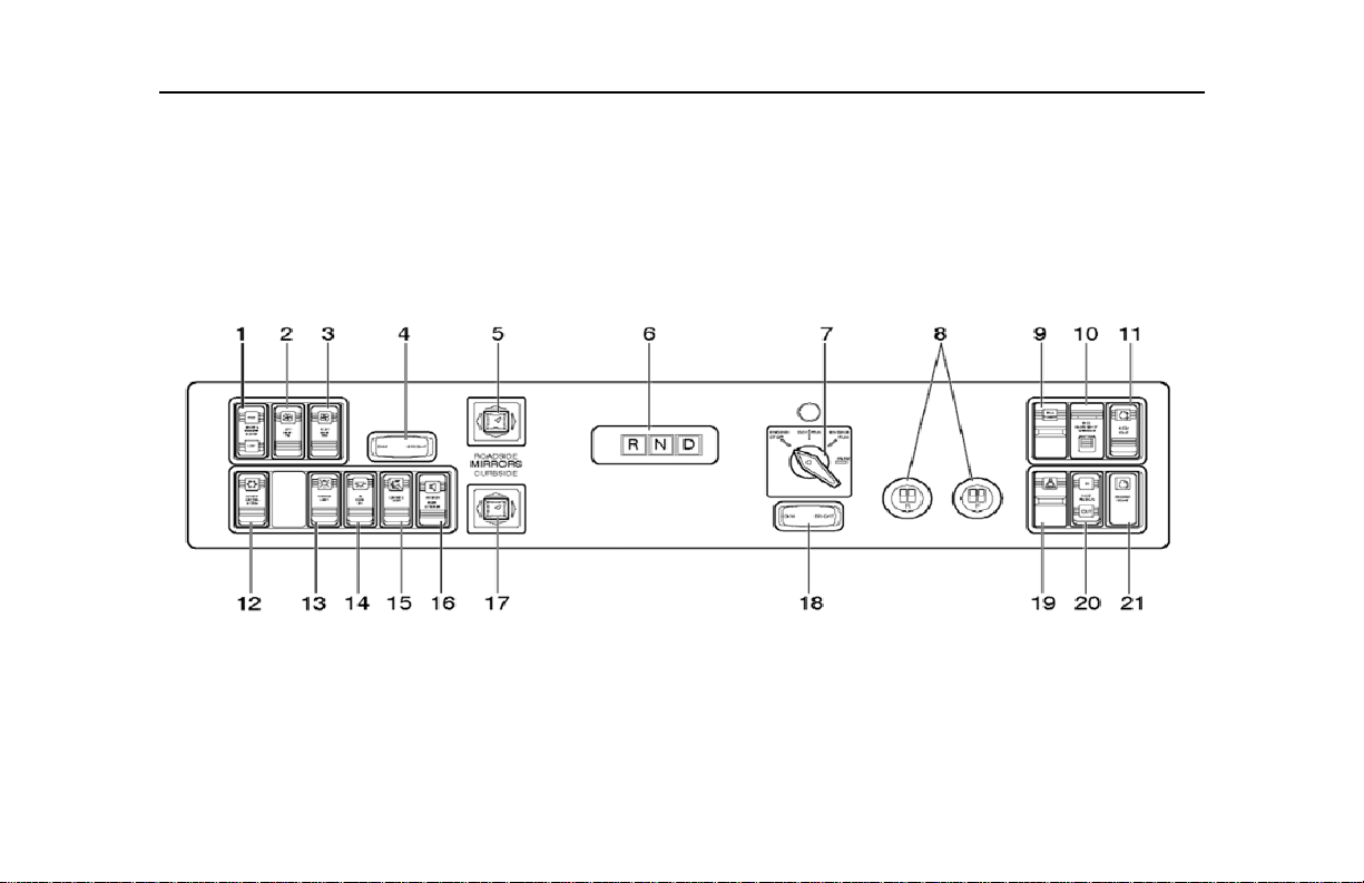
Driver’s Side Control Panel
LEGEND
1. Driver’s Booster Blower Switch
2. Left Dash Fan Switch
3. Right Dash Fan Switch
4. Driver’s Light Dimmer Switch
5. Roadside Mirror Control
6. Alternating Current Traction
Motor (ACTM) Gear Selector
7. Master Switch
8. Driver’s Push Button Door
Controller
9. Hill Holder Switch
10. Propulsion Control System (PCS)
Emergency Override Switch
11. High Idle Switch
12. Climate Control System Switch
13. Farebox Light Switch
14. Interior Light Switch
15. Driver’s Light Switch
16. Speakers Switch
17. Curbside Mirror Control
18. Instrument Panel Dimmer Switch
19. Hazard Switch
20. Foot Pedals Switch
21. Engine Start Switch
The driver’s side control panel is
equipped with controls for
activating, deactivating, and
overriding vehicle co ntrol syst em s.
Systems include interior and
exterior lighting, engine control,
door control, suspension kneeling,
climate control, and P.A. systems.
All are enabled/dis abled, depen ding
on the position of the Master Switch.
See “Master Switch” on page 25.
1. Driver’s Booster Blower
Switch
This three position (HIGH, O FF,
LOW) rocker switch allows the
operator to activate the
overhead blower unit in the
operator’s compartment, for
increased circulati on.
2. Left Dash Fan Switch
This three position (HIGH, O FF,
LOW) rocker switch allows the
operator to activate the lef t front
dash mounted fan.
3. Right Dash Fan Switch
This three position (HIGH, O FF,
LOW) rocker switch allows the
operator to activate the right
front dash mounted fan.
4. Driver’s Light Dimmer Switch
This momentary rocker switch
allows the operator to increase
or decrease the intensity of the
operator’s light; loca ted di rec t ly
above the operator.
5. Roadside Mirror Control
This four-way push button
control remotely adjust s the
exterior roadside mirror to the
operator’s individual needs.
The operator can adjust the
position of the mirror by
pushing the knob either UP,
DOWN, LEFT or RIGHT.
6. Alternating Current Traction
Motor (ACTM) Gear Selector
The drive modes available on
this selector are Drive (D),
Neutral (N), and Reverse (R).
For gear transition, Neutral
Page 20

must always be activated first.
NOTE
NOTE
NOTE
See “Gear Range Selector
Position” on page 43.
7. Master Switch
This four position rotary switch
enables various electrical
systems under the following
selected positions: ENGINE
STOP, DAY RUN, NIGHT RUN,
or PARK.
Switch” on page 25.
8. Driver’s Door Control Push
Buttons
The rear and front door
controller push buttons
provides the operator with
complete control over the front
and rear doors. Press once to
open and press again to close
the doors.
See “Master
When the front or rear door is
opened, the activated button will
remain illuminated until the door
is closed.
9. Hill Holder Switch
This two position momentary
(ON, OFF) rocker switch
manually activates the brake
interlock circuit to prevent the
vehicle from rolling w hen on an
inclined surface.
The throttle will still be active
while the Hill Holder switch is
activated. Releasing the Hill
Holder switch will release the
brake interlocks.
Driver’s Side Control Panel
Releasing the brake pedal while
the Hill Holder switch is in the
ON position and the doors are
closed, will cause the vehicle to
slowly creep forward.
10. PCS Emergency Override
Switch
This rocker switch will override
the HybriDrive™ protection
system. This will allow the
propulsion system to operate
with known faults for as long as
the switch is depressed.
T o activate the PC S Emergency
Override switch, release the
locking tab by pushing and
Page 21
 Loading...