

Page 1
DR13-A805C
I n s t a l l a t i o n a n d U s e r ’ s G u i d e
http://www.orionimages.com
All contents of this document may change without prior notice, and actual pro duct appearance may
differ from that depicted here in
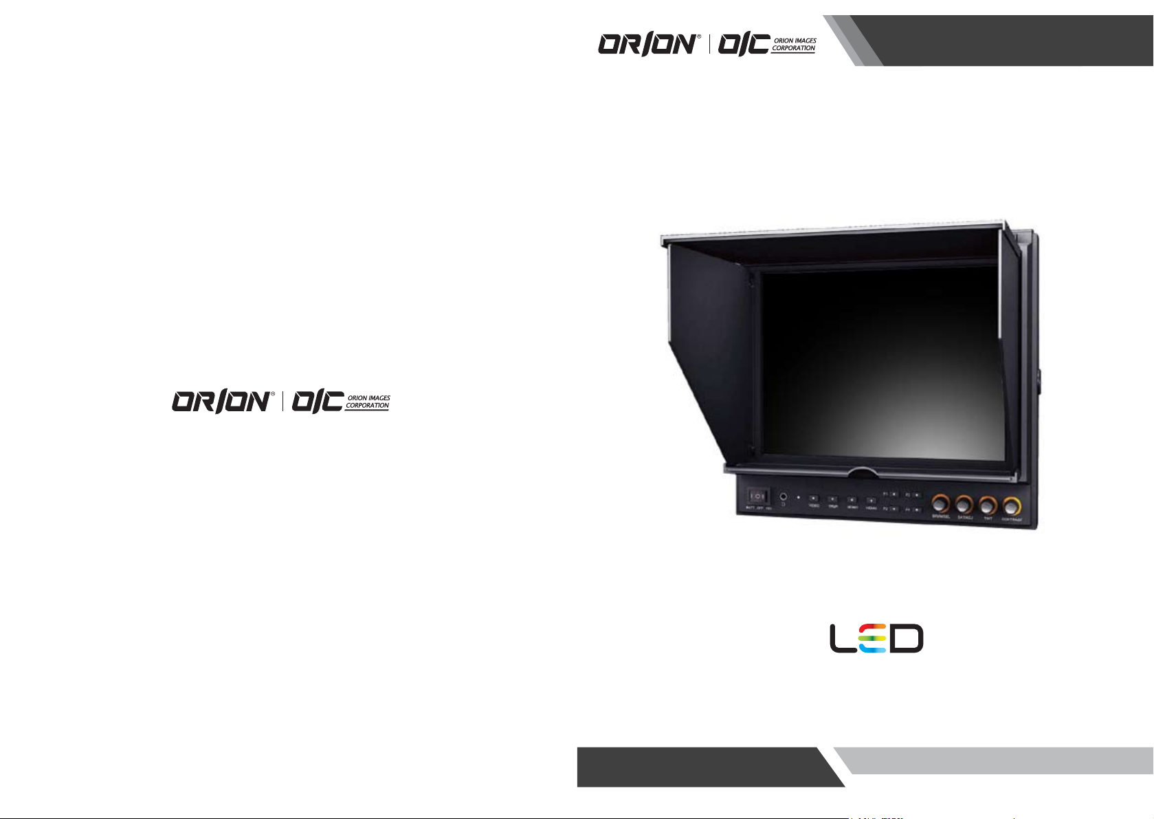
VF972HC
9.7” LED VIEWFINDER / FIELD
MONITOR (BROADCAST)
Page 2
http://www.orionimages.comhttp://www.orionimages.com
Ins t a llat i o n a n d Use r ’ s Gu i d eIns t a llat i o n a n d Use r ’ s Gu i d e
1. SAFETY INSTRUCTION
Follow this safety instruction to use the monitor prope rly and prevent the damages.
This safety instruction has “Warning” & “Caution” as below
Warning -
Caution -
Keep this user’s guide book for later use.
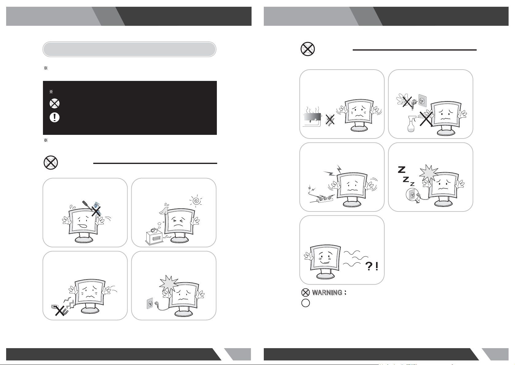
Warning
Never remove the back over and
touch the inside of the monitor.
If you need a service, please
contact the service center.
If the user does not follow this instruction,
it may cause the serious damage to the user.
If the user does not follow this instruction, it may cause the slight
damage to the user or cause some damages to the monitor.
Keep away the monitor from the
direct sunlight and a heating appliance.
Warning
Do not install this monitor on the outside
and near water. If may cause damage to
the product, electric shock and fire.
When lightning and thundering, unplug the
monitor from the wall outlet and never touch
it.
When smoking and noising from the monitor,
unplug the product from the wall outlet and
contact a service center.
For cleaning do not use liquid cleaners.
Never touch the power plug with wet-hands.
Unplug this product from the wall outlet, when
It does not operate for a long time.
Never push objects of any kind into
this product as they may result in
a risk of fire or electric shock.
Connect the power code to the wall
outlet tightly. If the power code or plug
are defective and the wall outlet is not
tight, please do not use them.
:
:
IIN
N
How to fix
G
G
A
W
R
N
N
A
W
R
Do not open this product as it contains high voltage inside.
It may create an electric shock.
It the user disassembles and remove the back cover, it does not make sure
to make up for the damages and do a service and exchange the monitor.
2 3
Page 3
http://www.orionimages.comhttp://www.orionimages.com
Cautions Cautions
Ins t a llat i o n a n d Use r ’ s Gu i d eIns t a llat i o n a n d Use r ’ s Gu i d e
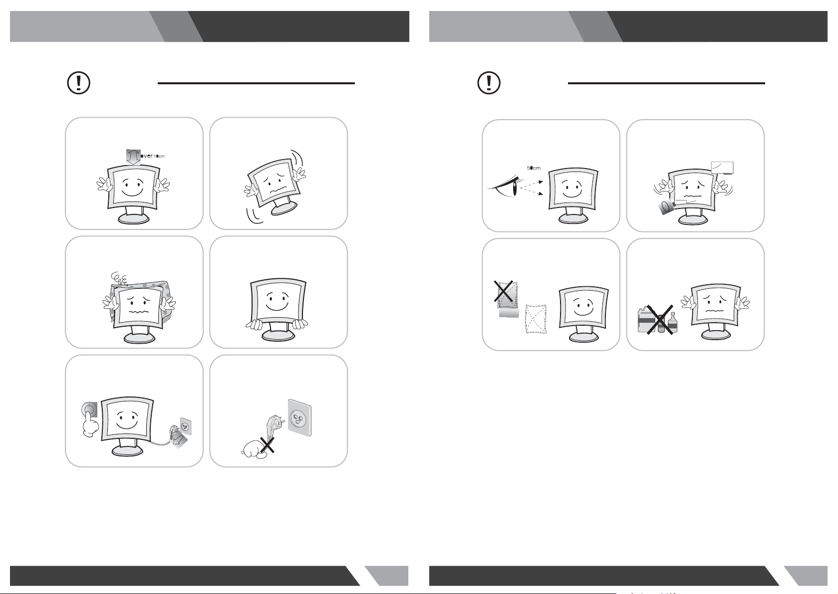
Install this monitor some distance
From the wall and do not install unless
Proper ventilation is provided.
The openings must not be blocked by
curtain, rug or other similar surface.
Before carrying the monitor, tum it off and
Unplug the signal cables and the power code
From the wall outlet.
Place this product on a stable place.
If not, it may fall, causing serious
Damages to the monitor and people.
When carrying this monitor, be careful
not to damage the panel and drop it
It may cause some trouble.
Take the power plug out from the wall
outlet.
Do not pull the cable. It may snap the innerwires and cause overheating and fire.
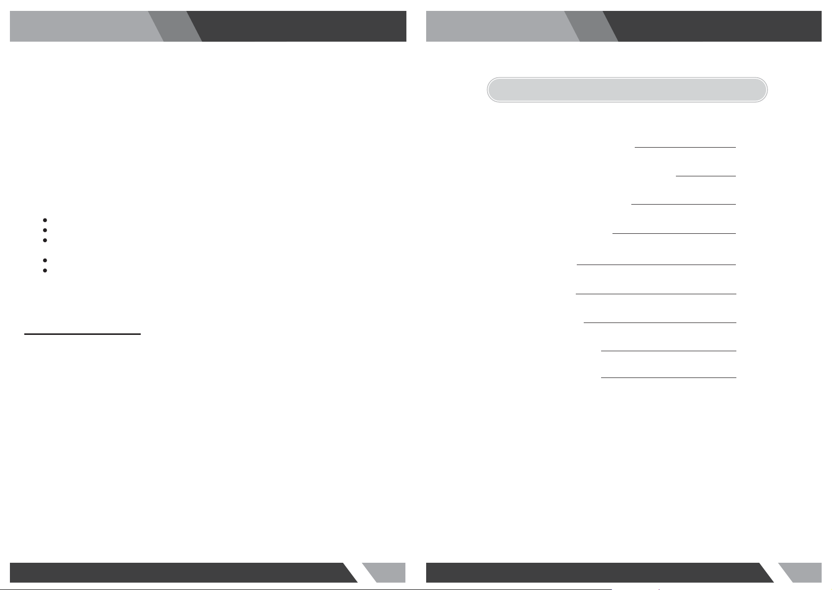
Install this monitor about 50cm far from
the eyes and an angle of 0~15 degrees
below eyes. Too close installation may
cause having weak sight.
For cleaning, unplug the monitor from the
Wall outlet. Do net use the liquid cloth.
Use the soft cloth.
Do not press the LCD panel with hands or
the sharpened material hardly.
Do not use the chemical liquid for cleaning.
It may cause fading and breakage.
4 5
Page 4
http://www.orionimages.comhttp://www.orionimages.com
Ins t a llat i o n a n d Use r ’ s Gu i d eIns t a llat i o n a n d Use r ’ s Gu i d e
FCC RF INTERFERENCE STATEMENT
NOTE
This equipment has been tested and found to comply with the limits for a Class A digital device, pursuant
to Part 15 of the FCC Rules. These limits are designed to provide reasonable protection against harmful
interference in a residential installation. This equipment generates, uses and can radiate radio frequency
energy and, if not installed and used in accordance with the instructions, may cause harmful
interference to radio communications. However, there is no guarantee that interference will not occur in a
particular installation. If this equipment does cause harmful interference to radio or television reception
which can be determined by turning the equipment off and on, the user is encouraged to try to correct
the interference by one or more of the following measures.
Reorient or relocate the receiving antenna.
Increase the separation between the equipment and receiver.
Connect the equipment into an outlet on a circuit different from that to which the receiver
is connected.
Consult the dealer or an experienced radio, TV technician for help.
Only shielded interface cable should be used.
Finally, any changes or modifications to the equipment by the user not expressly approved by the
grantee or manufacturer could void the users authority to operate such equipment.
DOC COMPLIANCE NOTICE
This digital apparatus does not exceed the Class A limits for radio noise emissions from digital apparatus
set out in the radio interference regulation of Canadian Department of communications.
2. TABLE OF CONTENTS
PRODUCTION DESCRIPTION
1
.
INSTALLATION OF SUNSHADE COVER
.2
DV BATTERY MOUNT PLATE
.3
WIRING INSTRUCTIONS
.4
SETTING MENU
.5
ACCESSORIES
.6
SPECIFICATIONS
.7
TROUBLESHOOTING
.8
.9
8
10
11
12
13
21
22
22
23LIMITED WARRANRY
6 7
Page 5

3. PRODUCT DESCRIPTION
http://www.orionimages.comhttp://www.orionimages.com
10. Knob BRI/M/SEL
Press the knob to access the menu function, pressing the knob in the menu to return to the
previous page or exit the menu.
*Rotate knob to select an option
Ins t a llat i o n a n d Use r ’ s Gu i d eIns t a llat i o n a n d Use r ’ s Gu i d e
*Default as Brightness function
VIDEO YPbPr HDMI1 HDMI2
6 7 8 9 10 11 12 135432
F1 F3
F2 F4
FRONT VIEW
1. TALLY (indicator light)
2. Battery Power On / Off switch
“II” is battery power, “O” is power off, “I” is DC power
3. Earphone jack
4. Power indicator light
ON/OFF (Light turns to red when power on)
5. VIDEO
Indicator lights up when signal switch to video state
6. YPbPr
Indicator lights up when signal switch to YPbPr state
7. HDMI1
Indicator lights up when signal switch to HDMI1 state
8. HDMI2
Indicator lights up when signal switch to HDMI2 state
9. F1, F2, F3, F4
User-definable buttons
F1
Peaking
F2
False Color
F3
1
BRI/MENU
Exposure
11. Knob SAT/ADJ
Press the knob to select main MENU options; rotate knob to confirm the selection and adjust
parameter values
*Default as Saturation function
12. Knob TINT
Default as Tint function
13. Knob CONTRAST
Default as Contrast function
1
2
3
9 10
TNT
SAT
CONT
6 8
7
1. Video signal output / input
2. Y signal input / output
3. Pb signal input / output
4. Pr signal input / output
5. Audio (L/R) input
4
5
REAR VIEW
10. Power cable interface (connecting
to the battery plate)
11. Speaker
12. TALLY signal input
13. 4-pin XLR DC power input
6. HDMI 1 signal input
7. HDMI 2 signal input
8. HDMI signal loop output
F4
Histogram
9. Mini USB input (Only for program upgrades,
do NOT use if non-professionals)
11
12
13
14
Pin Number
1 GND
2, 3
4
Signal
........
+12V
8 9
Page 6

http://www.orionimages.comhttp://www.orionimages.com
4. INSTALLATION 5. DV BATTERY MOUNT PLATE
Ins t a llat i o n a n d Use r ’ s Gu i d eIns t a llat i o n a n d Use r ’ s Gu i d e
4-1 Installation of Sunshade Cover
Pushing to close / open sunshade from assigned round area when assembly / disassembly.
(i.e. assembly instruction ② / disassembly instruction ①); otherwise assembly /
disassembly failed, and even damaged.
Assembly instructions
Push to close
1 2
Disassembly instructions
Push to open
5-1 Standard Mounts Precess
Following two types of battery plates
are suitable for this device, model
F970 & LP-E6.
F-970 LP-E6
5-2 DV Battery Mount Plate Specification
1
Model F970 for battery of SONY DV
DCR-TRV series, DCR-TRV E series, VX2100E PD P series, CCD-SC / TR3 / FX1E /
HVR-AIC, HDR-FX1000E, HVR-Z1C, HVR-V1C, FX7E F330
2
Model LP-E6 for battery of Canon DSLR
5D Mark II / EOS7D / EOS60D
5-3 V-mount battery plate (optional)
1 2
BB-IDX
10 11
Page 7

http://www.orionimages.comhttp://www.orionimages.com
Ins t a llat i o n a n d Use r ’ s Gu i d eIns t a llat i o n a n d Use r ’ s Gu i d e
5-4 Anton Bauer mount battery plate (optional)
6. WIRING INSTRUCTIONS
6-1 Power & TALLY cable
1
3
4
5
BB-AB
2
6. SETTING MENU
Before setting the functions, please make sure the device is connected correctly.
When power on, press BRI/M/SEL knob on the device, function menus will pop-up on the screen.
After confirm the option value, then press BRI/M/SEL knob to return to the previous, and press the
BRI/M/SEL knob again to exit the menu settings.
BRI/M/SEL knob: to select an option. SAT/ADJ knob to select the main menu, adjusting option
values and confirm the selection.
Color Temp
Settings: User, 6500º K, 7500º K, 9300º K.
Default: User
6
On User mode, user can adjust RGB gain and bias.
User mode is recommended for professional users only.
Check Field
1. XLR (M) connector: to connect the XLR connector on device.
2. DC Power adapter connector.
3. Red: for TALLY red light connector. (0 ~ 0.5V or short to No 5)
4. Green: for TALLY green light connector. (0 ~ 0.5V or short to No 5)
5. Black: for grounding.
6. XLR (F) connector: for the XLR adapter.
12 13
Settings: Off, Mono, Red, Green, Blue
Default: Off
Setting Mono, Red, Green or Blue display color
Aspect Ratio
Settings: 4:3, 16:9, Full Screen.
Default: 4:3
Setting screen aspect ratio: 4:3, 16:9 and full screen
Page 8

Pixel-to-Pixel
Setting: On, Off
Default: Off
Shows the original picture with 1:1 pixel mapping, if the picture is larger than the monitor’s LCD
resolution, the center part of the picture is shown. BRI / M / SEL knob operation you can see part of
the picture is not completely display.
Camera
Settings: 480P, 1080I
Default: 480P
http://www.orionimages.comhttp://www.orionimages.com
Ins t a llat i o n a n d Use r ’ s Gu i d eIns t a llat i o n a n d Use r ’ s Gu i d e
For 480P screen pixel DSLR camera, such as Canon 5D II camera
For 1080I screen pixel DSLR camera, such as Canon 5D III camera
H/V delay
Settings: Off, H&V delay, V delay, H delay.
Default: Off
H/V Delay allows you to check the outside signal of active picture area. This mode is for
broadcast professionals.
Underscan
Settings: On, Off
Default: Off
HDMI monitor can not display the best resolution pixel-to-pixel mode , the output resolution is smaller
than the display resolution , the display will appear black side of this situation is called HDMI underscan;
Conversely , the display You can not display the entire contents of the image that HDMI overscan.
Underscan / overscan principle each pixel point average tensile or compression so that the image can
be completely displayed on the screen.
Center Marker
Settings: On, Off
Default: Off
Set to display center marker or not.
Screen Markers
Settings: Off, 95%, 93%, 90%, 88%, 85%, 80%
Default: Off
The box -shaped mark display on or off can be set in accordance with the desired ratio.
Language
Settings: English, Chinese
Default: English
Set English / Chinese switch.
14 15
Page 9

http://www.orionimages.comhttp://www.orionimages.com
Ins t a llat i o n a n d Use r ’ s Gu i d eIns t a llat i o n a n d Use r ’ s Gu i d e
PIP
Settings: Small, Medium, Large, PBP, POP
Default: Small
PIP top life of the display default, Set small, medium, large screen in screen, as well as painting outside
source adjustments and interchangeable , the small screen , screen and big screen , you can also adjust
the display position , respectively, for the upper left , upper right , lower left and lower right.
Shortcut key of PIP function will be available after setting in the menu.
Input Format OSD
Settings: 5s, 10s, 15s
Default: 5s
The menu signal display period , display the length of time can be set according to individual needs.
LOGO
Settings: On, Off
Default: Off
Boot LOGO settings.
Freeze Input
Settings: On, Off
Default: Off
Lock screen displays the current mode.
Manufacturer Default
Settings: OK, Cancel
Default: Cancel
When on the picture shows size error, “Manufacturer default” operation of the equipment, which
restore the factory settings, the previous record on the device no default to factory settings. Reverse
the SAT / ADJ knob to select "OK"
ISP
For program upgrades, Please reboot your computer if press accidentally.
Peaking
Settings: Mono, Color
Default: Mono
Adjust Mono or Color.
Assistant Func.
Settings: Manual, Auto
Default: Auto
Auxiliary functions automatically. Automatically set to adjust the brightness , contrast and hue
corresponding menu function can also be set manually.
16 17
Page 10

Function of buttons and knobs can be customized by users’ needs.
Functions of F1-F4 buttons can also be customized: Aspect Ratio, Center Marker, Screen Marker, Check
Field, Color Bar, Camera, PIP, Zoom, Pixel-to-Pixel, Freeze Input, Underscan, H/V delay, Peaking,
False Color, Exposure and Histogram.
Long keep press any F1-F4 button to pop-up shortcut menu when screen without a menu. As follows
(item selected default as blue font):
http://www.orionimages.comhttp://www.orionimages.com
7. ACCESSORIES
7-1 Standard Accessories
Ins t a llat i o n a n d Use r ’ s Gu i d eIns t a llat i o n a n d Use r ’ s Gu i d e
Functions of R1-R4 buttons can also be customized: Contrast, Brightness, Saturation, Tint, Volume,
Sharpness and Back Light.
1
5 6 7
Name of Each PartNO. Qty
1
Flexible folding Sun Shade Cover 1 piece
2
Battery plate (F-970 / LP-E6)
Plate Bracket is attached to the Monitor
3
HDMI Type A-A
4
TALLY Connector
5
DC12V Power Adapter (XLR Connector)
6
12V DC adapter
7
Operation Manual
7-2 Optional Accessories
21 3
2 3
Name of Each PartNO. Qty
1
Gimbals Bracket
2
Anton Bauer Mount Battery Plate, BB-AB
3
V-mount Battery Plate, BB-IDX
4
2 pieces
1 piece
1 piece
1 piece
1 piece
1 piece
1 copy
1 piece
1 piece
1 piece
18 19
Page 11

http://www.orionimages.comhttp://www.orionimages.com
Ins t a llat i o n a n d Use r ’ s Gu i d eIns t a llat i o n a n d Use r ’ s Gu i d e
10. 1 YEAR LIMITED WARRANTY8. SPECIFICATIONS
Model No. VF972HC
Screen Size
Max. Resolution
Brightness
Contrast
Viewing Angle
Input Voltage
Input Signal
Power Requirement
Power Consumption
Size:(LWD)
Weight
*Design and specifications are subject to change without notice
CVBS, YPbPr, HDMI1, HDMI2 and Ear Phone Jack
100V AC to 240V AC (with AC Adaptor, XLR Connector)
246 × 224 × 31mm / 167.5mm (with cover open)
9.7’’ LED backlit
1024 x 768, support up to 1920 x 1080
400cd/㎡
600:1
178°/ 178° (H/V)
DC12V (XLR DC Connection)
≤18W
1068g / 1388g (with cover)
9. TROUBLE SHOOTING
1. Only black-and-white display
Check whether the color saturation is properly setup.
2. Power on but no pictures
Check whether the cables of Video, HDMI, YPbPr and SDI are correctly connected. Please use the
standard power adapter coming with the product package. Improper power input may cause the device.
3. Wrong or abnormal colors
Check whether the cables are correctly and properly connected. Broken or loose pins of the cables
may cause a bad connection.
All ORION Images products carry a limited warranty from ship date against defects in materials and
workmanship. ORION Images is not liable for improper in stallation that results in damage to mo unts,
adapters, display equipment or personal injury.
Contact ORION Images
In the event of missing and/or damage equipment, or tec hnical questions, the following informa tion can
help in the completion of the installation.
Address: 7300 Bolsa Avenue, Westminster, CA 92683
Tel: 714-766-6300 / Fax: 714-766-6310
Email: sales@orionimages.com
Website: ht tp://www.orionimage s.com
4. When on the picture shows size error
Press “BRI/MENU → Underscan” to zoom in / out pictures automatically When receiving HDMI signals.
5. Other problems
Please press “BRI/MENU” button and choose → Manufacturer Default → OK
6. According to the ISP, the machine can not function properly
ISP for program upgrades, non-professionals do not use. Please reboot your computer if press
accidentally!
* It is normal to see some bright lines appear on the screen when turn off the device.
20 21
Page 12

http://www.orionimages.comhttp://www.orionimages.com
Ins t a llat i o n a n d Use r ’ s Gu i d eIns t a llat i o n a n d Use r ’ s Gu i d e
MEMOMEMO
22 23
 Loading...