

Page 1
INSTRUCTION MANUAL
Orion® VersaGo™
Altazimuth Mount
#5682
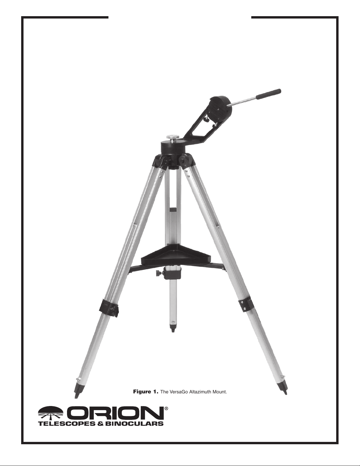
Figure 1. The VersaGo Altazimuth Mount.
Providing Exceptional Consumer Optical Products Since 1975
Customer Support (800)-676-1343
E-mail: support@telescope.com
Corporate Offices (831)‑763‑7000
89 Hangar Way, Watsonville, CA 95076
IN 303 Rev. B 02/09
Page 2
Congratulations on your purchase of a quality Orion product. Your VersaGo Altazimuth Mount is a sturdy,
yet highly portable observing platform for small telescopes. The simple design makes setting up and
using the mount very easy. Teflon bearing surfaces for both axes of motion insure smooth telescope
pointing, even when making very small, precise positional adjustments. Great for daytime terrestrial or
nighttime astronomical applications, you’ll find yourself observing more and fussing with equipment less
when using the VersaGo.
These instructions will help you set-up, properly use, and care for your mount. Please read them over
thoroughly before getting started.
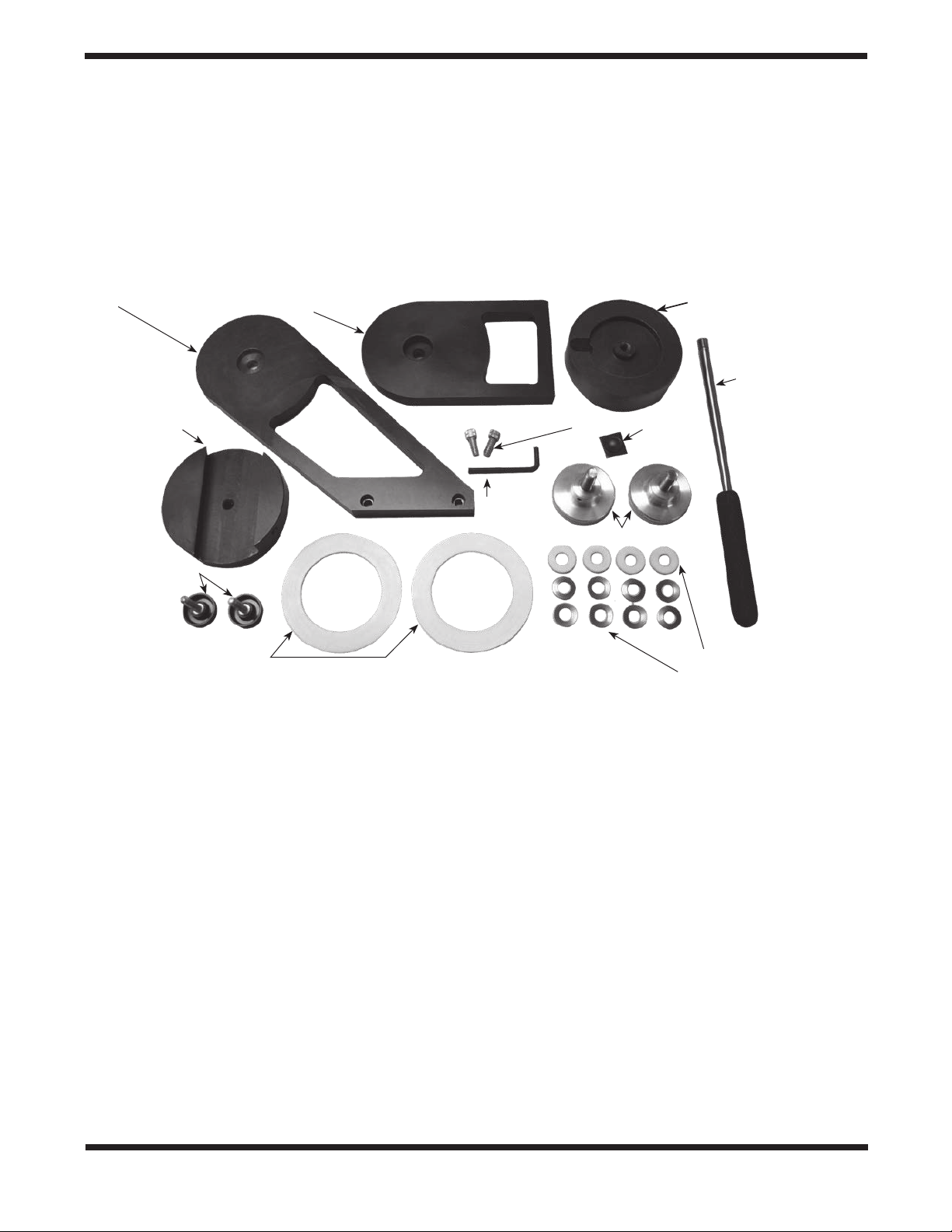
Arm
Dovetail holder
Thumb screws (2)
Large Teflon bearing rings (2)
Figure 2. Parts included with the VersaGo mount (tripod and accessory tray not shown).
Upper base
Socket head cap screws (2)
Hex key
1. Parts List
(refer to Figure 2)
2. Assembly
Lower base
Handle
Rubber
bumper
Knobs (2)
Small Teflon rings (4)
Disc springs (8)
Qty. Description
1 Tripod
1 Accessory tray (with 3x wing screws)
1 Arm
1 Upper base
1 Lower base
1 Dovetail holder
2 Knobs
1 Handle
2 Large Teflon bearing rings
4 Small Teflon rings
8 Disc springs
2 Thumb screws
2 Socket head cap screws
1 Hex key
1 Rubber bumper
2
Carefully open all of the boxes in the shipping container. Make
sure all the parts listed in the Parts List are present. Save the
boxes and packaging material. In the unlikely event that you
need to return the mount, you must use the original packaging.
Initially assembly of the mount should only take about 20-30
minutes. No tools, other than the provided hex key, are needed. Refer to Figure 1 during assembly.
1. Assemble the arm to the upper base. This is done with the
two socket head cap screws. Orient the parts as shown in
Figure 3. The groove in the upper base should register with
the slot in the arm. Insert the screws through the holes in
the arm and into the upper base. Tighten the screws firmly
with the hex key.
Page 3
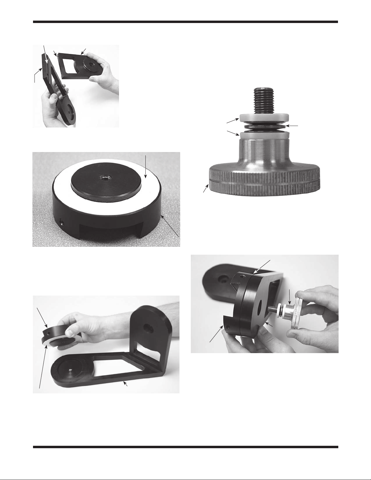
Slot
Arm
Upper baseGroove
Figure 3. Connect the
arm to the upper base
with the two socket head
cap screws. The groove
in the upper base should
align with the slot in the
arm.
4. Place a small Teflon ring onto one of the knob shafts. Then,
place four of the disc springs onto the knob shaft. The disc
springs should be stacked with their curved surfaces facing away from each other. Place another small Teflon ring
on top of the disc springs. The knob should now appear as
shown in Figure 6.
2. Place a large Teflon bearing ring on the dovetail holder as
shown in Figure 4.
Large Teflon
bearing ring
Dovetail holder
Figure 4. Place one of the large Teflon bearing rings on the
dovetail holder.
3. Position the dovetail holder on the arm as shown in Figure
5. The Teflon bearing surface seats between the dovetail
holder and the arm.
Small Teflon rings (2)
Disc springs
(4), stacked
with curved
surfaces facing
away from
each other
Knob
Figure 6. Two small Teflon rings and four disc springs go on
each knob shaft. The disc springs should be oriented so their
curved surfaces face away from each other.
5. Push the knob shaft through the hole in the arm and thread
it into the hole in the dovetail holder (Figure 7). Thread the
knob unit just tight.
Teflon bearing (not visible)
Knob
Dovetail holder
Arm
Large Teflon bearing ring
Figure 5. The dovetail holder seats into the arm with the Teflon
bearing in between.
Arm
Dovetail
holder
Figure 7. The knob goes through the arm and into the dovetail
holder. The Teflon bearing seats between the arm and dovetail
holder.
3
Page 4

6. Place the other large Teflon bearing ring onto the lower
base as shown in Figure 8.
Large Teflon
bearing ring
Lower base
Figure 8. Place a large Teflon bearing ring onto the lower base.
7. Place the remaining two small Teflon rings and four disc
springs onto the other knob shaft, the same as in step 4.
8. Place the upper base over the lower base, then pass the knob
shaft through the hole in the upper base and thread it into the
hole in the lower base (Figure 9). Thread the knob until just
tight.
9. Stand the tripod upright and spread the legs apart. Tighten
the leg lock knobs at the base of the tripod legs. For now,
keep the legs at their shortest (fully retracted) length; you
can extend them to a more desirable length later, after the
mount is completely assembled.
10. Spread the tripod legs apart as far as they will go, until the
accessory tray bracket is taut. Attach the accessory tray
to the accessory tray bracket with the three wing screws
already installed in the tray. This is done by pushing the
bolts up through the holes in the bracket, and then threading them into the holes in the accessory tray (Figure 10).
The tray gives the tripod extra stability and is a convenient
area to place telescope accessories during use.
Accessory tray
Tripod leg
Wing screw
Upper base
Accessory tray bracket
Figure 10. Attach the accessory tray to the tripod’s tray bracket
with the three wing screws that come installed in the tray.
Hole
Post
Knob under
tripod head
Knob with small
Teflon rings (2) and
disc springs (4)
Teflon bearing ring Lower base
Figure 9. Position the upper base over the lower base, and
connect the parts by passing the knob through the upper base and
threading it into the lower base. The Teflon bearing ring should seat
between these parts.
4
Figure 11. The post on the tripod head goes into the hole on
the underside of the lower base. The VersaGo mount connects to
the tripod with the knob under the tripod head; be sure to tighten
this knob firmly.
Page 5

Handle
Dovetail
holder
Thumb screws (2)
Figure 12. The thumb screws and handle thread into the
dovetail holder.
11. Place the VersaGo mount onto the tripod. The post on the
tripod head should go into the slot on the underside of the
lower base (Figure 11). Thread the knob under the tripod
head up into the threaded hole in the lower base. Tighten
this knob firmly.
12. Thread the two thumb screws into the dovetail holder as
shown in Figure 12.
3. Connecting a Telescope
The VersaGo mount was designed to be used with telescopes
of apertures 6" or less; telescopes larger than this will not be
able to point at the horizon (horizontal) or zentith (vertical).
Also, for best results, the telescope optical tube assembly
should not weight more than approximately 15 lbs; otherwise,
it may not provide adequate stability.
To connect a telescope, a dovetail mounting bar or dovetail
adapter is required. Some telescopes have a dovetail bar
directly attached to the telescope tube. For other telescopes,
tube rings will be required to couple the dovetail bar to the
tube. Dovetail mounting bars and tube rings are both available from Orion (Figure 14). Additionally, if your telescope has
a 1⁄4"-20 threaded mounting hole, Orion offers two different
dovetail adapters that will thread into this hole; one orients the
bar parallel to the tube (the 1⁄4"-20 dovetail adapter), the other
orients the bar perpendicular to the tube (the 1⁄4"-20 dovetail
L-adapter, see Figure 14).
1⁄4"-20
Dovetail
adapter
1⁄4"-20
Dovetail
L-adapter
Rubber bumper
Upper base
Azimuth
tensioning
knob
Figure 13. The rubber bumper on the azimuth tensioning knob
will prevent larger telescope tubes from hitting the knob when
pointing near the horizon.
13. Connect the handle to the dovetail holder as shown in Figure
12. There are two threaded holes where the handle can be
attached; use the one that positions the handle in the most
convenient location for your usage.
14. Attach the adhesive-backed rubber bumper to the center of
the knob that connects the upper and lower base (Figure
13).
Your VersaGo mount is now fully assembled, and should
resemble Figure 1. All that is left is to connect your telescope
to the mount.
Tube rings
Dovetail mounting bar
Figure 14. Orion sells a variety of optional mounting bars, 1/4"-
20 adapters, and tube rings that will couple your telescope to the
VersaGo mount.
Once you have a dovetail mounting bar on your telescope
tube, connecting the telescope to the mount is exceptionally
easy. First, unthread the thumb screws on the VersaGo’s dovetail holder until the screw tips are flush with the interior wall of
the dovetail holder. Then, insert the telescope’s dovetail bar
into the mount’s dovetail holder, and tighten the two thumb
screws firmly.
If you have a telescope with a dovetail mounting bar attached
directly to the tube, the finderscope may be oriented in an
awkward position when connected to the VersaGo. In most
cases, this should not cause any problems in actual usage.
If you wish to orient the telescope differently, you will need to
purchase optional tube rings and a dovetail mounting bar so
the tube can be rotated within the rings. Likely, you will also
need to remove the mounting bar already connected directly
to the telescope’s tube.
5
Page 6

a.
ly, and moving the dovetail bar slightly forward or back in the
dovetail holder. If you are using tube rings, you can move the
telescope tube forward or back in the tube rings. When the
telescope doesn’t move up-and-down by itself when the arm’s
tensioning knob is not very tight, you have achieved good balance (Figure 15a-c).
4. Using the VersaGo Mount
The VersaGo mounts allows motion of the telescope in two
axes: altitude (up-and-down) and azimuth (left-to-right). Hence,
the VersaGo is an “altazimuth” mount (Figure 16). Simply move
the telescope up-or-down and left-to-right. The handle provides
a convenient way to position the mount’s axes.
Altitude
Azimuth
b.
c.
Figures 15a-c: The telescope is not balanced because it is
front-heavy. (b.) The telescope is too back-heavy. (c.) The telescope
is properly balanced on the altitude axis.
If you are using the 1/4"-20 dovetail adapter and the finder
scope and/or eyepiece is positioned awkwardly, you may want
to consider purchasing the 1⁄4"-20 dovetail L-adapter.
For best up-and-down motion, the telescope should be balanced front-to-back when positioned horizontally. You can
balance the telescope by loosening the thumb screws slight-
Figures 16. The VersaGo is an “altazimuth” mount because it
can move in altitude (up-and-down) and azimuth (left-to-right).
If the motion of one or both of the axes is too loose or too
tight, you can adjust the bearing tensioning by tightening or
loosening the knobs. You should be able to adjust these knobs
so even the smallest motions of the mount are very smooth.
If the motion on the altitude axis is not smooth no matter how
the altitude tensioning knob is adjusted, then you will need to
better balance the telescope front-to-back.
Unlike many altazimuth mounts, the VersaGo can be used to
point a telescope at zenith (straight up). This makes it especially well suited for astronomical observing.
6
Page 7

When pointing a longer telescope tube, like a long focal length
refractor, at zenith, extending the tripod legs will help better
position the eyepiece. For heavier telescopes, we recommend
extending the tripod legs in order to give the mount a wider
stance; this will prevent the mount from becoming “tippy”.
For 5" or larger aperture telescopes, the telescope tube may
bump the azimuth tensioning knob when pointing near the
horizon. The rubber bumper will prevent any tube scratches or
dings if this happens. For smaller telescope tubes the rubber
bumper should not be needed, and can be removed.
Tracking Celestial Objects
Celestial objects appear to move slowly across the sky
because of the rotation of the Earth on its polar axis. When
you observe an object through your telescope, you’ll see it drift
gradually across the field of view. To keep the object centered
in the field, use the handle to move the VersaGo as needed.
For these small, precise movements, you may need to readjust the axis tensioning knobs. Keep in mind that objects will
appear to move faster at higher magnifications, because the
field of view is narrower.
5. Care and Maintenance
If you give your VersaGo mount reasonable care, it will last a
lifetime. Store it in a clean, dry, dust-free place. Do not store
the mount outdoors, although storage in a garage or shed is
OK.
Your mount requires very little mechanical maintenance. It is
constructed of aluminum and has a black anodized finish that
is fairly scratch-resistant. If a scratch does appear, it will not
harm the mount. Dust, dirt, or moisture on the mount should
be wiped off with a soft cloth. If the mount needs more extensive cleaning, use a household surface cleaning fluid.
When transporting the mount to an observing location, we
recommend removing the handle in order to prevent it from
being damaged. You can also fold the tripod legs together
once the accessory tray is removed. For extra portability, you
can also remove the VersaGo mount entirely from the tripod;
simply unthread the knob under the tripod head. To protect
your mount during transport, Orion offers optional soft padded carry cases.
Telescope connection: Requires Orion dovetail
mounting bar (not
included)
Tripod: Adjustable height,
includes accessory tray
Assembled weight: 12 lbs. 3 oz.
6. Specifications
Mount: Altazimuth
Material: Aluminum black
anodized throughout
Maximum load capacity: Approximately 15 lbs.
Maximum tube outer diameter: Approximately 7.5" (6"
aperture telescope)
Bearing surfaces: Teflon
Axis tensioning: Via knurled knobs
Pointing handle: Included, foam grip
7
Page 8

One-Year Limited Warranty
This Orion VersGo™ Altazimuth Mount is warranted against defects in materials or workmanship for a
period of one year from the date of purchase. This warranty is for the benefit of the original retail purchaser
only. During this warranty period Orion Telescopes & Binoculars will repair or replace, at Orion’s option, any
warranted instrument that proves to be defective, provided it is returned postage paid to: Orion Warranty
Repair, 89 Hangar Way, Watsonville, CA 95076. If the product is not registered, proof of purchase (such as
a copy of the original invoice) is required.
This warranty does not apply if, in Orion’s judgment, the instrument has been abused, mishandled, or
modified, nor does it apply to normal wear and tear. This warranty gives you specific legal rights, and
you may also have other rights, which vary from state to state. For further warranty service information,
contact: Customer Service Department, Orion Telescopes & Binoculars, 89 Hangar Way, Watsonville, CA
95076; (800)-676-1343.
Orion Telescopes & Binoculars
89 Hangar Way, Watsonville, CA 95076
Customer Support Help Line (800)‑676‑1343 • Day or Evening
8
 Loading...