

Page 1

www.orioncontrols.com
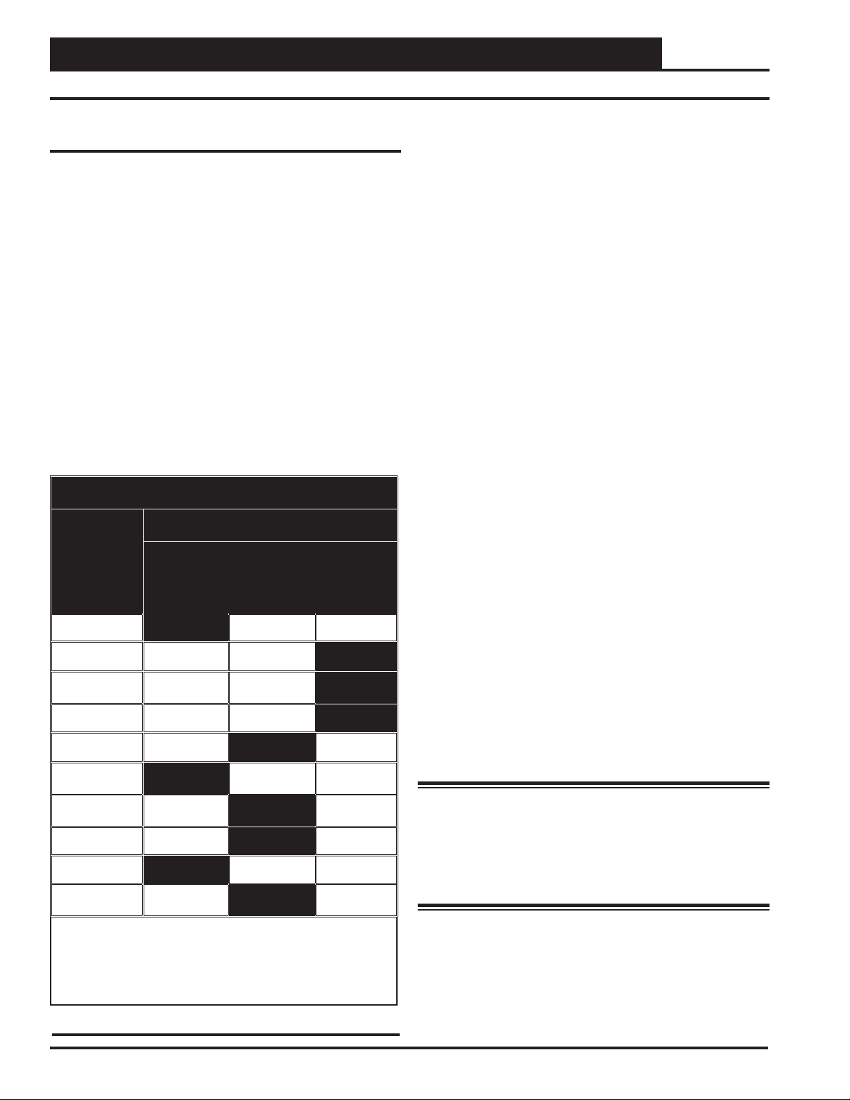
LED BLINK CODES
LED NAME STATUS1 STATUS2
NORMALOPERATION 0 1
SATFAIL 1 2
OATFAIL 2 2
SPCFAIL 3 2
MODULEALARM 4 2
MECHCOOL FAIL 1 3
MECHHEAT FAIL 2 3
FANPROOF FAIL 3 3
DIRTYFILTER 4 3
EMERGENCYSHUTDOWN 5 3
LOWSAT 1 4
HIGHSAT 2 4
CONT.TEMP COOL FAIL 3 4
CONT.TEMP HEAT FAIL 4 4
PUSHBUTTON OVR 1 5
ZONEOVR 2 5
OUTPUTFORCE ACTIVE 0 6
VCM-X E-BUS Component &
System Wiring Technical Guide
Use For VCM-X E-BUS Controller Code: SS1030 and later
For VCM Wiring Information, See Component & System Wiring
Technical Guide - Form: OR-VCMWIRE-TGD
RS-485 COMMUNICATION LOOP. WIRE
“R” TO“R”, “T” TO “T” “SHLD” TO “SHLD”
www.aaon.com
www.orioncontrols.com
VCM-X MODULAR E-BUS CONTROLLER
Orion No.:OE332-23E-VCMX-MOD-A
AI1 = SPC (SPACETEMPERATURE SENSOR)
= SAT(SUPPLY AIR TEMPERATURE SENSOR)
AI2
= RAT(RETURN AIR TEMPERATURE SENSOR)
AI3
AI4
= OAT(OUTDOOR AIR TEMPERATURE SENSOR)
AI5
= SUCTION PRESSURE SENSOR (FROM EXP. MODULE)
AI7
= SPACETEMPERATURE SENSOR SLIDE ADJUST
OR VOLTAGE RESETSOURCE
A01
= ECONOMIZER (2-10 VDC OUTPUT)
A02
= SUPPLYFAN VFD (0-10 VDC OUTPUT)
E-BUS
CONNECTOR
ANALOG INPUT
JUMPER
SETTINGS
THERM
4-20mA
AI1
0-10V
0-5V
THERM
4-20mA
AI2
0-10V
0-5V
THERM
4-20mA
AI3
0-10V
0-5V
THERM
4-20mA
AI4
0-10V
0-5V
THERM
4-20mA
AI5
0-10V
0-5V
THERM
4-20mA
AI7
0-10V
0-5V
ANALOG INPUTJUMPER SETTINGS
MUSTBE SET AS SHOWN FOR
PROPER OPERATION
STATIC
PRESSURE
WattMaster Label
#LB102073-01-A
Rev.: 1A
WARNING!POLARITY MUST BE OBSERVED
OR THE CONTROLLER WILLBE DAMAGED
2
IC
EXPANSION
RELAYCONTACT
RATING IS 1AMP
MAX @ 24 VAC
RELAY
COMMON
FAN
RELAY2
RELAY3
RELAY4
RELAY5
AAON No.:
V07150
24 VAC POWER ONLY
2
I C DIGITAL
SENSOR
Page 2

Table of Contents
SYSTEM OVERVIEW, INSTALLATION & COMMISSIONING ...............................................................5
Systems Overview ..................................................................................................................................................6
System Installation ..................................................................................................................................................8
Transformer Sizing & Cabling - Devices Without Modular Connectors ............................................................9
Transformer & Wire Sizing - Devices With Modular Connectors ....................................................................10
System Commissioning .......................................................................................................................................20
SYSTEM CONFIGURATIONS ............................................................................................................21
Stand Alone System Wiring ..................................................................................................................................22
Interconnected System Wiring ..............................................................................................................................23
Networked Single Loop System With CommLink Only .........................................................................................24
Networked Single Loop System With MiniLink PD & Modular VAV/Zone Controllers ...........................................25
Networked Single Loop System With MiniLink PD & Non-Modular VAV/Zone Controllers ...................................26
Networked Single Loop System With CommLink, MiniLink PD & Modular VAV/Zone Controllers ........................27
Networked Single Loop System With CommLink, MiniLink PD & Non-Modular VAV/Zone Controllers ................28
Networked Multiple Loop System Wiring With Modular VAV/Zone Controllers .....................................................29
Networked Multiple Loop System Wiring With Non-Modular VAV/Zone Controllers .............................................30
VCM-X E-BUS CONTROLLER WIRING .............................................................................................31
Main Controller Wiring ..........................................................................................................................................32
Main Controller Addressing ...................................................................................................................................33
Digital Room Sensor Wiring ..................................................................................................................................34
Wall-Mounted CO
Sensor Wiring .........................................................................................................................34
2
Duct-Mounted CO2 Sensor Wiring ........................................................................................................................35
Space Temperature Sensor Wiring .......................................................................................................................36
Remote Supply Air Reset Wiring ...........................................................................................................................36
Supply Air, Return Air, and Outdoor Air Temperature Sensor Wiring ....................................................................37
Economizer Damper Actuator Wiring ....................................................................................................................38
Supply Fan VFD & Bypass Damper Actuator Wiring ............................................................................................39
VCM-X EXPANSION, 4 BINARY INPUT, & 12 RELAY EXPANSION MODULE WIRING .....................41
VCM-X Expansion Module Input Wiring ................................................................................................................42
VCM-X Expansion Module Output Wiring .............................................................................................................43
Suction Pressure Transducer Without Digital Compressor Wiring ........................................................................44
Suction Pressure Transducer With Digital Compressor Wiring .............................................................................45
Expansion Module Binary Input Wiring .................................................................................................................46
4 Binary Input Expansion Module Wiring ..............................................................................................................47
Outdoor Air Humidity Sensor Wiring .....................................................................................................................48
2
WattMaster Controls Inc.
8500 NW River Park Drive · Parkville , MO 64152
Toll Free Phone: 866-918-1100
PH: (816) 505-1100 · FAX: (816) 505-1101 · E-mail: mail@wattmaster.com
Visit our web site at www.orioncontrols.com
Form: OR-VCMXWIRE-TGD-01B Copyright June 2015 W attMaster Controls, Inc.
AAON
WattMaster Controls, Inc. assumes no responsibility for errors, or omissions.
This document is subject to change without notice.
is a registered trademark of AAON, Inc., Tulsa, OK.
VCM-X Component & Systems Wiring
Page 3

Table of Contents
Indoor Wall Mounted Humidity Sensor Wiring ......................................................................................................49
Return Air Humidity Sensor Wiring .......................................................................................................................50
Title 24 Economizer Actuator Feedback Wiring ....................................................................................................51
Building Pressure Sensor, Actuator & VFD Wiring ................................................................................................52
Modulating Heating Wiring ....................................................................................................................................53
Modulating Cooling Wiring ....................................................................................................................................54
Return Air Bypass Wiring ......................................................................................................................................55
12 Relay Expansion Module Wiring ......................................................................................................................56
Airfl ow Monitoring Station Wiring ..........................................................................................................................57
MODULAR & NON-MODULAR VAV/ZONE CONTROLLER DIAGRAMS .............................................. 59
Modular VAV/Zone Controller Actuator Package Wiring .......................................................................................60
Non-Modular VAV/Zone Controller Actuator Package Wiring ...............................................................................61
Expansion Module Wiring .....................................................................................................................................62
Slaved Zone Wiring ...............................................................................................................................................68
COMMUNICATION DEVICES DIAGRAMS ........................................................................................69
System Manager SD Modular Cable Connections ...............................................................................................70
System Manager SD Cable Pigtail - Wiring Detail ................................................................................................71
System Manager SD Networked Wiring ...............................................................................................................72
Modular Service SD Tool Connections..................................................................................................................73
System Manager Touch Screen II to VCM-X E-BUS Controller Wiring.................................................................74
System Manager Touch Screen II to VAV/Zone Controller Wiring ........................................................................75
CommLink 5 Connections & Wiring ......................................................................................................................76
IP Module Installation Instructions ........................................................................................................................77
On-Site Computer Connection ..............................................................................................................................78
Remote Site Computer Connection ......................................................................................................................79
USB-Link 2 Connections & Wiring ........................................................................................................................80
MiniLink Polling Device Wiring Using Modular Connectors ..................................................................................81
MiniLink Polling Device Wiring Using Wire Terminals ...........................................................................................82
Power/Comm Board Wiring - When Used For Local Loop Devices ......................................................................83
Power/Comm Board Wiring - When Used For Network Loop Devices .................................................................84
ADD-ON DEVICES DIAGRAMS .........................................................................................................85
Lighting Panel Wiring For Standard Lighting Contactors ......................................................................................86
GPC-X Controller Wiring .......................................................................................................................................87
GPC-X Controller - Address Switch Setting ..........................................................................................................88
GPC-XP Controller Wiring.....................................................................................................................................89
GPC-XP Controller Addressing & Baud Rate Setting ...........................................................................................90
GPC-XP Controller On-Board CommLink 5 Setting ..............................................................................................91
GBD-X Controller - CO
GBD-X Controller - Space Temp. Sensor Averaging Wiring .................................................................................94
GBD-X Controller Address Switch Setting ............................................................................................................96
Applications Wiring .........................................................................................................92
2
VCM-X Component & Systems Wiring
3
Page 4

Table of Contents
MODULE WIRING & CONNECTIONS ...............................................................................................97
HP1C Module Wiring ............................................................................................................................................98
HP2C2 Module Wiring ..........................................................................................................................................99
Full Digital Module Wiring ...................................................................................................................................100
Dual Digital Module Wiring ..................................................................................................................................101
MODGAS-X Controller Wiring - Single Modulating Valve - No Staging ..............................................................102
MODGAS-X Controller Wiring - Two Modulating Staged Valves ........................................................................103
MODGAS-XWR Controller Wiring - Single Modulating Valve - No Staging ........................................................104
MODGAS-XWR Controller Wiring - Single Modulating Valve & 1 Fixed Stage...................................................105
MODGAS-XWR Controller Wiring - Two Modulating Staged Valves ..................................................................106
MHGRV-X Controller Wiring................................................................................................................................107
WSHP-X2 Controller Wiring - Single Circuit .......................................................................................................108
WSHP-X2 Controller Wiring - Dual Circuit ..........................................................................................................109
PREHEAT-X Controller Wiring ............................................................................................................................110
MODGAS II Controller Wiring ..............................................................................................................................111
MHGRV II Controller Wiring ................................................................................................................................112
MHGRV III Controller Wiring ...............................................................................................................................113
MISCELLANEOUS DIAGRAMS & TECHNICAL INFORMATION .......................................................115
Modular Room Sensor Wiring .............................................................................................................................116
EPROM Chip Locations ......................................................................................................................................117
EPROM Chip Installation Procedures .................................................................................................................120
Updating Modules with the Service Tool SD .......................................................................................................121
Temperature & Humidity Sensor Voltage-Resistance Tables ..............................................................................123
Pressure Sensors Voltage-Resistance Tables ....................................................................................................124
Suction Pressure Transducer Testing ........................................................................................... ......................125
4
VCM-X Component & Systems Wiring
Page 5

Systems Overview
System Overview,
Installation &
Commissioning
VCM-X Component & System Wiring
5
Page 6

Systems Overview
System Types
Overview
The Orion system components can be confi gured into several types
of systems. It is a good idea to become familiar with the different
types of systems and their architecture by reading the information in
this section and looking at the confi guration diagrams in the System
Confi gurations section of this manual. The information below is de-
signed to help you understand how the system components integrate
with each other and the available confi guration options.
System Types
Four different system confi gurations are available depending on
the type and number of controllers that you have on your system.
1. Stand Alone
(See Figure 3, page 22 for Connection Diagram)
Interconnected
This system consists of a group of VCM-X E-BUS Controllers
interconnected with communication cable to allow programming
from one central location. Broadcasting between controllers is not
available. Programming and status monitoring are accomplished by
one or more of the following methods.
1. By using an operator interface. This can be a Modular
System Manager, a System Manager TS II, a Modular
Service Tool, or all 3 devices.
2. A computer interface can also be used in conjunction
with the other operator interfaces listed above, or by
itself. This requires a CommLink 5 or USB-Link 2 and a
personal computer with the Prism 2 computer front end
software installed.
2. Interconnected
(See Figure 4, page 23 for Connection Diagram)
3. Networked Single Loop
(See Figures 5-9, pages 24-28 for Connection
Diagrams)
4. Networked Multiple Loop
(See Figures 10-11, pages 29-30 for Connection
Diagrams)
5. Computer, CommLink 5, IP Module, USB-Link 2
(See Figures 54-58, pages 76-80 for Connection
Diagrams)
System Type Definitions
Stand Alone
This system consists of a single VCM-X E-BUS Controller. Programming and status monitoring are accomplished by one or more
of the following methods.
1. By using an operator interface. This can be a Modular
System Manager, a System Manager TS II, a Modular
Service Tool, or all 3 devices.
2. A computer interface can also be used in conjunction
with the other operator interfaces listed above, or
by itself. This requires a CommLink 5 or USB-Link 2
and a personal computer with the Prism 2 computer
front end software installed.
Networked Single Loop
The Networked Single Loop system, as its name implies, consists of
a single communications loop. This loop utilizes a network device to
share information that is broadcast from one controller to all controllers on the loop. The system can consist of the following devices.
1. A series of VCM-X E-BUS Controllers that utilizes
a network device to share information that is broadcast
from one controller to all controllers on the loop.
2. A single VCM-X E-BUS Controller and a series of VAV/
Zone Controllers. These VAV/Zone Controllers can
either be of the Modular type or Non-modular type.
The Modular type use Power/Comm Boards and
prefabricated cables and the Non-Modular type utilize
terminals and 2 conductor twisted pair with shield wire.
A network device is used to share information which is
broadcast back and forth between all controllers on the
loop.
These systems require a network device in the form of either a
CommLink 5 communications interface or a MiniLink Polling Device. Both network devices may also be used together. Programming
and status monitoring are accomplished by the following methods:
1. By using an operator interface. This can be a Modular
System Manager, a System Manager TS II, a Modular
Service Tool, or all 3 devices.
2. A computer interface can also be used in conjunction
with the other operator interfaces listed above, or
by itself. This requires a CommLink 5 or USB-Link 2
and a personal computer with the Prism 2 computer
front end software installed.
6
When using the MiniLink Polling Device alone, only the System
Manager, System Manager TS II, and Modular Service Tool can be
used to program and monitor the system. With the addition of the
CommLink 5, the Prism 2 computer front end software and a PC
can be used to program and monitor the system in addition to the
Modular Service Tool, Modular System Manager, and the System
Manager TS II.
VCM-X Component & System Wiring
Page 7

Systems Overview
Communication Devices
Networked Multiple Loop
The Networked Multiple Loop System consists of two or more loops,
each being called a “Local Loop”, with one “Network Loop” that
ties the “Local Loops” together. Each of these loops can consist of
one of the following groups of controllers:
1. A series of VCM-X E-BUS Controllers.
2. A single VCM-X E-BUS Controller and a series of VAV/
Zone Controllers. These VAV/Zone Controllers can
either be of the Modular type or Non-modular type.
The Modular type use Power/Comm Boards and
prefabricated cables and the Non-Modular type utilize
terminals and 2 conductor twisted pair with shield wire.
A network device is used to share information which is
broadcast back and forth between all controllers on the
loop.
To form the Networked Multiple Loop System, the following network
devices are required:
1. A MiniLink Polling Device is required per loop
(Local Loop). This allows the controllers to share
information that is broadcast from one controller to all
controllers on that local loop.
2. One CommLink 5 is required for the entire system.
It resides on the Network Loop and allows for
communications between all the local loops and
provides for global broadcasts to all controllers on the
entire system.
Programming and status monitoring are accomplished by one or
more of the following methods:
1. By using an operator interface. This can be a Modular
System Manager, a System Manager TS II, a Modular
Service Tool, or all 3 devices. The Modular System
Manager, System Manager TS II, or Modular Service
Tool connect to any “Local Loop” on the system.
2. A computer interface can also be used in conjunction
with the other operator interfaces listed above, or by
itself. This requires a personal computer with the Prism
II computer front end software installed connected to
the CommLink 5.
Network Communications Devices
MiniLink Polling Device
The MiniLink Polling device is used in the following applications:
1. This device is required on all Zoning applications. It is
optional on single loop VAV systems.
2. This device is required on each local loop of all
Networked Multiple Loop systems.
3.
This device is responsible for local loop broadcasts only.
It always resides on the local loop.
For a Networked Single Loop VCM-X E-BUS system, this device
can be used for tenant logging and alarm reporting to a Modular System Manager or System Manager TS II. It can be used to broadcast
information such as outside air temperature or outside air humidity
to all devices on the local loop. It can also be used to broadcast space
temperature from a GPC-X or GPC-XP Controller to any controllers
on this loop that do not have their own Space Temperature Sensor.
For a Networked Single Loop VAV system, the MiniLink Polling
Device can be used for tenant logging and alarm reporting to a
Modular System Manager or System Manager TS II. It must be used
to broadcast information such as, internal schedule, supply air temperature, fan and heat status, unoccupied calls for heating and cooling
from the VAV/Zone Controllers, and forced modes of operation.
For a Networked Single Loop Zoning system, this device must be
used for zone voting, because it calculates the heating and cooling
totals on the loop and broadcasts cooling, venting, and heating
modes to the VCM-X E-BUS Controller. It can also be used for
tenant logging and alarm reporting to the Modular System Manager
or System Manager TS II.
CommLink 5
The CommLink 5 device is used in the following applications.
1. A CommLink 5 is required on all Networked Multiple
Loop Systems.
2. A CommLink 5 is optional on all Networked Single
Loop Systems.
3. A CommLink 5 is required on any system when a
permanent computer interface is desired. The USB-Link
2 can be used for temporary computer connection for
setting up or servicing the system, but does not have the
complete functionality that the CommLink 5 provides.
The CommLink 5 is responsible for local loop broadcasts on a Networked Single Loop system, and on this type of system, the Loop
switch on the back of the CommLink must be set to “Single.” This
device is responsible for network broadcasts on Networked Multiple
Loop systems. On this type of system, the Loop switch on the back
of the CommLink must be set to “Multiple.”
For a Networked Single Loop VCM-X E-BUS system, this device
can be used for tenant logging and alarm reporting to a Modular
System Manager or System Manager TS II. It can also be used to
broadcast information like outside air temperature or outside air humidity to all local loops on the entire networked system. It may also
be used to broadcast space temperature from a GPC-X or GPC-XP
Controller to any controllers on the local loop that do not contain
their own Space Temperature Sensor.
On a Networked Single Loop VAV/Zone system, the CommLink
5 can be used to broadcast information such as internal schedule,
supply air temperature, fan and heat status, unoccupied calls for
heating and cooling, and forced modes of operation to and from the
VAV/Zone Controllers.
VCM-X Component & System Wiring
7
Page 8
System Installation
Wiring Considerations
Wiring Considerations
Before beginning installation, please study the wiring diagrams
for the controllers you are using with your particular application.
These diagrams appear in this manual and can also be found in the
technical guides supplied with your specifi c controllers. Wire and
transformer sizing instructions and examples are found in Figures
1 & 2, pages 9-10 of this manual.
The Modular VAV/Zone Controllers are equipped with modular connections. Non-Modular VAV/Zone Controllers have wiring terminals
instead of modular connectors. The VCM-X E-BUS Controller
is supplied with modular connectors. The Power/Comm board is
supplied with both terminals and a modular connector on the input
side. All of its outputs use modular connectors. The Minlink Polling
Device is equipped with both modular and wiring terminal blocks.
W e recommend (when possible) using modular cables instead of hard
wiring to wire terminal blocks to save installation time and eliminate
wiring errors. In some cases, however, hard wiring is unavoidable.
The table below lists the various Orion devices/controllers and their
available termination type(s) for communications and power wiring.
Communications And Power Wiring
Terminations For Orion Products
Available Power And Communications
Orion
Controller Or
Device
VCM-X E-BUS X
VAV/Zone •X
Power/Comm
Board
MiniLink PD X
CommLink 5 X
*Modular System
Manager
System Manager
TS II
GPC-X X
GPC-XP X
Lighting
Controller
* The System Manager is supplied with a pigtail connector that has a
modular plug on one end and stripped wires on the other end. The pigtail is
used to allow wiring connection to the HVAC unit controller wire terminals
and to a 24 VAC power transformer on systems that do not use Power/
Comm boards.
Modular
Connectors
Only
X
Connections
Wire
Terminals
Only
X
X
Both
Modular
Connectors
And Wire
Terminals
X
Power/Comm Board Requirements
Standard Connection Confi gurations and Use
Power/Comm boards are typically used on Networked, Single, and
Multiple Loop systems to transfer 24 VAC power and “Local Loop”
communications to Modular VAV/Zone Controllers, Modular System
Managers, or other Power/Comm boards.
The Power/Comm board must always be powered by its own dedicated 24 VAC transformer connected to its 2-wire, 24 VAC input
terminals (TB1).
Local Loop communications can be transferred to the Power/Comm
Board via a modular cable connected to its “Comm In” modular
connector input terminal (P2). This modular cable connection can
originate from the “Local Loop” modular connector of the MiniLink PD for this loop, another Power/Comm board output on the
same loop, or a Modular VAV/Zone Controller or Modular System
Manager output on the same loop. A Power/Comm board can also
be connected if desired to the “Local Loop” by hard wiring a 2-wire
shielded cable connected between its 3-wire communications input
terminal (TB1) and a Power/Comm board, or the MiniLink PD
“Local Loop”, 3-wire communications terminal.
For detailed wiring diagrams, see the Power/Comm board wiring
diagrams in the “Communication Devices Diagrams” section of this
manual. For Power/Comm board transformer sizing, see Figures 1
& 2, pages 9-10 of this manual.
Alternative Connection Confi guration and Use
If desired, the Power/Comm board can also be used to transfer both
24 VAC power and “Network Loop” communications to multiple
MiniLink PDs. Connection between the MiniLink PD(s) and Power/
Comm board(s) is accomplished by using modular cables between
the Power/Comm board’s modular output connectors and the MiniLink PD(s)’s “Network Loop” modular input connectors. When a
Power/Comm board is used to connect power and communications
to MiniLink PDs in this manner, that particular Power/Comm board
cannot also be used to share communications and/or power with
Modular VAV/Zone Controllers or Modular System Manager(s).
Warning: Do not ground the 24 VAC transformer that
is to be used with the Power/Comm board. Grounding of
the transformer will damage the Power/Comm board and
all boards connected to it. A separate transformer must be
used for each Power/Comm board. No exceptions. Do not
connect any other devices to the transformer used for the
Power/Comm board!
For detailed wiring diagrams, see the Power/Comm board wiring
diagrams in the “Communication Devices Diagrams” section of
this manual.
For Power/Comm board transformer sizing, see Figures 1 & 2,
pages 9-10 of this manual.
Table 1: Communications and Power Terminations
8
VCM-X Component & Systems Wiring
Page 9

System Installation
FILENAME
DATE:
DESCRIPTION:
PAGE
Wire & Transformer Sizing
JOB NAME
O-VCMXWRSIZ1A.CDR
Orion VCM-X System
24 VAC Power - Transformer & Wire Sizing Considerations for Devices Without Modular Connectors
Component Power Requirements
120 / 24VAC
120 / 24VAC
Distance A to B cannot exceed 57.80 Ft.
Distance from A to B cannot exceed 115.60 Ft.
Distance from A to C cannot exceed 115.60 Ft.
Distance from A to B cannot exceed 230.40 Ft.
Distance from A to C cannot exceed Ft.
Distance from A to D cannot exceed Ft.
Distance from A to E cannot exceed Ft.
230.40
230.40
230.40
120 / 24VAC
Some installers like to use one large 24 VAC transformer to power several devices. This is allowable as long as polarity is maintained to each device
on the transformer circuit.
Using
separate transformers also allows redundancy in case of a transformer failure. Instead of having 8 controllers inoperative because of a malfunctioning
transformer you have only 1 controller off line. If the installer does decide to use a large transformer to supply power to several devices, the following
transformer and wire sizing information is presented to help the installer correctly supply 24 VAC power to the devices.
Following is a typical example to help the installer to correctly evaluate transformer and wiring designs.
Each GPC-XP Controller requires 8 VA @ 24VAC power. In the examples below we have a total of 8 GPC-XP Controllers.
8 GPC-XP Controllers @ 8 VA each................ 8 x 8 VA = 64 VA.
The above calculation determines that our transformer will need to be sized for a minimum of 64 VA if we are to use one transformer to power all the
controllers.
Next we must determine the maximum length of run allowable for the wire gauge we wish to use in the installation. Each wire gauge below has a
voltage drop per foot value we use to calculate total voltage drop.
18ga wire.................................0.00054 = voltage drop per 1’ length of wire
16ga wire.................................0.00034 = voltage drop per 1’ length of wire
14ga wire.................................0.00021 = voltage drop per 1’ length of wire
For our example we will use 18 gauge wire. WattMaster recommends 18 gauge as a minimum wire size for all power wiring.
Next use the voltage drop per foot value for 18 gauge wire from the list above and multiply by the total VA load of the 8 controllers to be installed.
0.00054 (Voltage drop per foot for 18 gauge wire) x 64VA controller load = Volts/Ft.
WattMaster controllers will operate efficiently with a voltage drop no greater than 2 Volts. Divide the total allowable voltage drop of 2 Volts by the
number you arrived at above and you have the maximum number of feet you can run the 18 gauge wire with an 75 VA transformer with no more than a
2 Volt drop at the farthest controller from the transformer..
2 (Volts total allowable voltage drop)
= 57.80
0.0346 (Voltage drop per 1 ft. @ 64VA load)
Parallel circuiting of the wiring instead of wiring all 8 controllers in series allows for longer wire runs to be used with the same size wire (as shown in
our examples below).
Warning: If polarity is not maintained, severe damage to the devices may result. WattMaster Controls recommends
using a separate transformer for each device in order to eliminate the potential for damaging controllers due to incorrect polarity.
0.0346
feet
It is often necessary for the installer to calculate and weigh the cost and installation advantages and disadvantages of wire size,
transformer size, multiple transformers, circuiting, etc., when laying out an installation. No matter what layout scheme is decided upon, it is mandatory
that the farthest controller on the circuit is supplied with a minimum of 22 Volts.
GPC-X Controller ............................8 VA
VCM-X E-BUS Controller ................8 VA
GPC-XP Controller ..........................8 VA
Lighting Panel Controller .....10 VA
MiniLink Polling Device..........6 VA
A
A
A
BCDE
B
BC
1 of 2
01/07/13
VAV/Zone Controller.........................6 VA
Transformer Sizing & Wiring For Devices W/Out Modular Connectors
Figure 1: Transformer & Wire Sizing - Devices without Modular Connectors
VCM-X Component & Systems Wiring
9
Page 10
System Installation
FILENAME
DATE:
B. CREWS
DESCRIPTION:
PAGE
DRAWN BY:
Wire & Transformer Sizing
JOB NAME
2 of 22 of 2
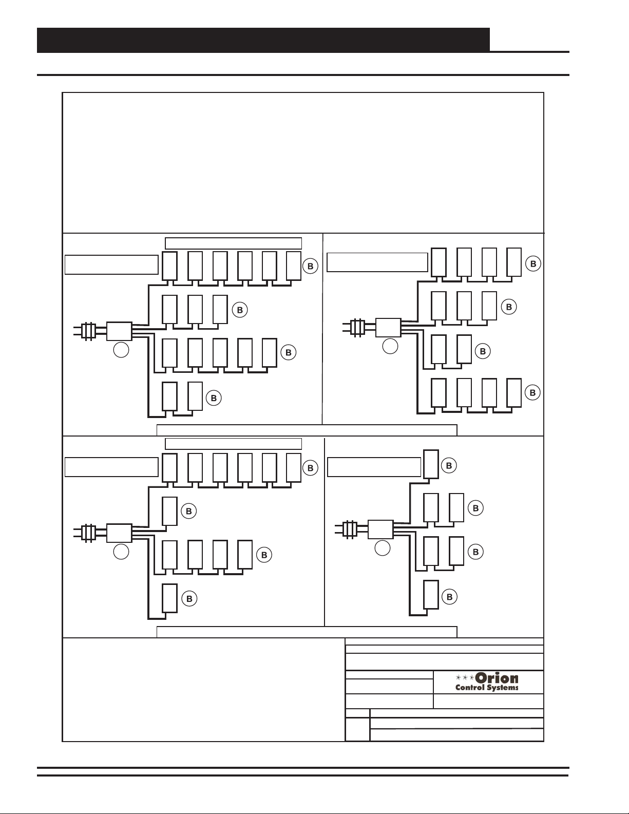
24VAC Power - Transformer & Cabling Considerations for Devices With Modular Connectors
Modular devices include the VAV/Zone Controller, Modular
System Manager & MiniLink Polling Device. When sizing
transformers for the devices it is important to design your
layout so that the fewest number of Power/Comm distribution
boards and the least number of transformers can be used.
The polarity problem discussed in regards to other devices
that do not have modular connections is not an issue with the
modular devices as they cannot be connected with reversed
polarity because of the modular board connectors and cable.
Also the prefabricated cable is always 16 gauge. Wire size
selection is therefore not an issue with the modular devices.
However, the same minimum voltage rules apply to modular
devices as with other non-modular devices. In order to
simplify wiring design and layout with modular devices the
following rules apply:
Power/Comm Board maximum transformer size = 100VA.
This is due to the board circuitry and fusing. Each modular
device is to be calculated at 6VA. This allows for a maximum
of 16 devices per Power/Commboard. If more than 16
devices are required, multiple Power/Comm boards must be
used.
No more than 6 modular devices allowed per branch circuit.
(The Power/Comm board has a total of 4 branch circuits)
The longest total run per branch circuit is 240 Ft. This is due
to voltage drop on the prefabricated cable.
Below are some examples of transformer sizing and branch
circuit design.
120 / 24VAC
120 / 24VAC
120 / 24VAC
120 / 24VAC
80 VA
Transformer
Minimum
See Warning
Note Below
40 VA
Transformer
Minimum
See Warning
Note Below
100 VA
Transformer
Minimum
See Warning
Note Below
75 VA
Transformer
Minimum
See Warning
Note Below
Power/Comm
Board
Power/Comm
Board
Power/Comm
Board
Power/Comm
Board
Total length of all modular cables used on each branch ( A to B) cannot exceed 240 Ft.
Total length of all modular cables used on each branch ( A to B) cannot exceed 240 Ft.
A
A
A
A
12 Devices At 6 VA = 72 VA
Use 75 VA Transformer
WARNING!
DO NOT GROUND THE 24V TRANSFORMER THAT IS TO BE USED
WITH THE POWER/COMM BOARDS. GROUNDING OF THE
TRANSFORMER WILL DAMAGE THE POWER/COMM BOARD AND
ALL BOARDS CONNECTED TO IT. A SEPARATE TRANSFORMER
MUST BE USED FOR EACH POWER/COMMBOARD. NO
EXCEPTIONS. DO NOT CONNECT ANY OTHER DEVICES TO THE
TRANSFORMER USED FOR THE POWER/COMM BOARD!
6 Devices At 6 VA = 36 VA
Use 40 VA Transformer
16 Devices At 6 VA = 96 VA
Use 100 VA Transformer
13 Devices At 6 VA = 78 VA
Use 80 VA Transformer
6 Devices Maximum Per Branch Circuit
6 Devices Maximum Per Branch Circuit
O-VCMXWRSIZ1A.CDR
Orion VCM-X System
03/09/06
Transformer Sizing & Cabling For Devices With Modular Connectors
Figure 2: Transformer & Wire Sizing - Devices with Modular Connectors
10
VCM-X Component & Systems Wiring
Page 11

System Installation
Stand-Alone
MiniLink Polling Device (MiniLink PD)
Standard Connection Confi gurations and Use
The MiniLink PD is used on Networked Single and Multiple Loop
systems to provide two-way communication between all devices on
it’s “Local Loop” and to all the other “Network Loop” devices on
the entire system. The MiniLink PD is equipped with both modular
connectors and hard wiring terminal blocks for connection of 24
VAC power “Local Loop” and “Network Loop” communications.
Each MiniLink PD is normally hard wired to a 24 VAC power
source connected to its 24 VAC input terminal (TB1). “Network
Loop” communications are transferred between multiple MiniLink
PDs by modular cables connected to their “Network Loop” modular connectors (P3 and P5). A CommLink 5 must be connected to
one of the MiniLink PDs on the system by using a 2-wire shielded
cable connected between its 3-wire “Network Loop” communications terminal block (TB4) and to the CommLink’s “485 Loop”
terminal block. Transfer of “Local Loop” communication from the
MiniLink PD to a Power/Comm board is made by using a modular
cable connected between the MiniLink PD “Local Loop” modular
connector (P4) and the Power/Comm board modular “Comm In”
connector (P2). If desired as an alternative, transfer of “Local Loop”
communication from the MiniLink PD to a Power/Comm board can
be made by hard wiring a 2-wire shielded cable connected between
the MiniLink PD’s 3-wire communications terminal (TB1) and the
3-wire communications input (TB1) on the Power/Comm board.
Installation Procedures
The installation procedures that follow are based on recommended
methods of wiring connection and controller installation. Installation
procedures vary depending on the type of system you are installing.
The system you are installing could be a Stand Alone, Interconnected,
Networked Single Loop, or Networked Multiple Loop system. The
Networked System also has installation variations based on the type
of components you are installing for that system. The following
information explains the procedures for all of these systems. Please
fi nd the system and components that closely match your system and
follow the outlined procedures.
Stand Alone Systems
See Figure 3, page 22 of this manual for a detailed Stand Alone
System wiring diagram. Also see pages 9-10 for wire and transformer
sizing information. Y ou should review these diagrams before attempting connections or powering up the controller or interface devices.
1. Install a 24 VAC, 8 VA minimum, transformer for the
VCM-X E-BUS Controller and wire from transformer
to the controller using 18 gauge minimum, 2 conductor
cable for power. Observe polarity on all power wiring.
2. The Modular Service Tool SD connects to the controllers
using the supplied cable with DIN connectors on both
ends. The connection point on the controller is located
near the communications connector. The Comm unications setting must be set to Lo Speed Stand
Alone.
3. The Modular System Manager SD comes supplied with
a 12 foot modular cable with a modular connector on
one end and stripped wires on the other. If the Modular
System Manager is to be mounted in a remote location,
run 18 gauge, 2 conductor shielded cable for
communications from the controller’s 3 wire
communications terminal to a junction box. Run 18
gauge minimum, 2-wire, power wires from a separate
24 VAC, 6 VA minimum transformer into the
junction box. Splice the modular cable to the
communications and power wire inside of the junction
box by making solid connections, using wire nuts or butt
splice connectors. The Communications setting must be
set to Lo Speed Stand Alone.
4. The System Manager TS II utilizes a 3-wire
communication terminal block for connection to any
controller on the communications local loop that has
communication wire terminals. A separate transformer
is required for the System Manager TS II. It has a 2-wire
24 VAC terminal block for connection to a 24 VAC
transformer. The transformer should be sized to provide
6 VA minimum power and should be connected using
using 18 gauge minimum 2 conductor wire. In the
Settings Menu, enter
Address.
5. If a CommLink 5 is used for a computer interface,
connect communications using 18 gauge, 2 conductor
with shield cable. Connect from the controller’s 3-wire
communications connector to the CommLink’s 3-wire
communications connector. For this type of system, the
Loop switch located on the back of the CommLink 5
must be set to “Single”.
6. Use 18 gauge minimum, 2-wire cable for all 24 VAC
power wiring. Be sure to maintain polarity on all boards.
If a CommLink is connected, use the 110 VAC/24 VAC
power supply furnished with the CommLink for its
power source.
7. Before powering up the controller, set the desired board
address on the controller (usually 1).
<0> for the System Manager
VCM-X Component & Systems Wiring
11
Page 12

System Installation
Interconnected & Networked Single Loop
Interconnected Systems
See Figure 4, page 23 for a detailed Interconnected System wir-
ing diagram. Also see pages 9-10 for wire and transformer sizing
information. You should review these diagrams before attempting
connections or powering up the controller or interface devices.
1. Connect all VCM-X E-BUS Controllers in a daisy chain
format using 18 gauge, 2 conductor shielded cable for
communications. Install a separate 24 VAC, 8 VA
minimum transformer for each VCM-X E-BUS
Controller and wire the transformers to each
controller using 18 gauge minimum, 2 conductor cable.
Observe polarity on all boards.
2. The Modular Service Tool SD will connect to any of
the controllers using the supplied cable with DIN
connectors on both ends. The connection point on the
controller is located near the communications connector.
The Communications setting must be set to Lo Speed
Stand Alone.
3. The Modular System Manager SD comes supplied with
a 12 foot modular cable with a modular connector on
one end and stripped wires on the other. If the Modular
System Manager is to be mounted in a remote location,
run 18 gauge, 2 conductor shielded cable for
communications from the controller’s 3-wire
communications terminal to a junction box. Run 18
gauge minimum, 2-wire power wires from a separate
24 VAC, 6 VA minimum transformer into the junction
box. Splice the modular cable to the communications
and power wire inside of the junction box by making
solid connections, using wire nuts or butt splice
connectors. The Communications setting must be set
to Lo Speed Stand Alone. .
4. The System Manager TS II utilizes a 3-wire
communication terminal block for connection to any
controller on the communications local loop that has
communication wire terminals. A separate transformer
is required for the System Manager TS II. It has a 2-wire
24 VAC terminal block for connection to a 24 VAC
transformer. The transformer should be sized to provide
6 VA minimum power and should be connected using 18
gauge minimum 2 conductor wire. In the Settings Menu,
enter
sure One to One Unit Connection is not selected.
5. If a CommLink 5 is used to provide for connection to a
computer interface, connect communications using 18
gauge, 2 conductor shielded cable. Connect from one
of the controller’s 3-wire communications connectors
to the CommLink’s 3-wire communications connector.
For this type of system, the Loop switch on the back of
the CommLink needs to be set to “Single”.
<0> for the System Manager Address and make
6. Use 18 gauge minimum, 2-wire cable for all 24 VAC
power wiring. Be sure to maintain polarity on all boards.
If a CommLink 5 is installed, use the 110 VAC/24 VAC
power supply furnished with the CommLink for its
power source.
7. Before powering up the controllers, set each controller’s
board address to a unique number from 1 through 60.
Networked Single Loop Systems
See Figures 5-9, pages 24-28 for detailed Networked Single Loop
System wiring diagrams. Also see pages 9-10 for wire and transformer sizing information. Y ou should review these diagrams before
attempting connections or powering up the controller or interface
devices.
Loop Containing VCM-X E-BUS Controllers Only
(Using CommLink 5)
1. Connect all VCM-X E-BUS Controllers on the loop in a
daisy chain format using 18 gauge, 2 conductor shielded
cable wiring from each controller’s communication
terminals to the next controller’s communication
terminals. Install a separate 24 VAC, 8 VA minimum
transformer for each controller and wire from controllers
to the transformers using 18 gauge minimum, 2 wire
cable. Be sure to observe polarity on all boards.
2. Connect 18 gauge minimum 2 conductor shielded cable
from one of the VCM-X E-BUS Controller’s 3 wire
communication terminals to the CommLink5’s 3 wire
communications terminal. The Loop switch on the
back of the CommLink must be set to “Single” for this
installation. Use the 110 VAC/24 VAC power supply
furnished with the CommLink for its power source.
3. The Modular Service Tool SD will connect to any of the
controllers using the supplied cable with DIN connectors
on both ends. The connection point on the controller
is located near the communications connector. The
Communications setting must be set to Lo Speed
Network Mode.
4. The Modular System Manager SD comes supplied with
a 12 foot long modular cable with a modular connector
on one end and stripped wires on the other. If the System
Manager is to be mounted in a remote location, run 18
gauge, 2 conductor shielded cable for communications
from one of the controller’s 3 wire communications
terminals to a junction box. Run 18 gauge, 2 wire, 24
VAC power wires supplied by a separate transformer
into the junction box. Splice modular cable to the
communications and power wire inside of the junction
box using solid connections from wire nuts or buttsplice connectors. The Modular System Manager MUST
always be connected on the “Local Loop”, never the
“Network Loop”. The Communications setting must be
set to Lo Speed Network Mode.
12
VCM-X Component & Systems Wiring
Page 13

System Installation
Networked Single Loop
5. The System Manager TS II utilizes a 3 wire
communication terminal block for connection to any
controller on the communications local loop that has
communication wire terminals. A separate transformer
is required for the System Manager TS II. It has a 2
wire 24 VAC terminal block for connection to a 24 VAC
transformer. The transformer should be sized to provide
6 VA minimum power and should be connected using
18 gauge minimum, 2 conductor wire. In the Settings
Menu, enter
6. Before powering up the controllers, set each controller’s
board address to a unique number from 1 through 59.
Loop Containing VCM-X E-BUS Controller with Modular
VAV/Zone Controllers and MiniLink PD Only
1. Connect all controllers in a daisy chain format
using 18 gauge, 2 conductor shielded cable for
communications. Using 18 gauge minimum, 2 wire
cable for power, install a 24 VAC, 8 VA minimum,
transformer for the VCM-X E-BUS Controller and
wire from the transformer to the VCM-X E-BUS
Controller. Using 18 gauge minimum, 2 wire cable
for power, install a separate 24 VAC transformer sized
for the required VA load for each Power/Comm board on
the loop and wire from each transformer to its Power/
Comm board. Observe polarity on all boards.
2. Connect 2 conductor shielded cable from the VCM-X
E-BUS Controller’s 3 wire communications connector
to the MiniLink PD’s 3 wire communications connector
marked “Local Loop”. Use 18 gauge minimum, 2 wire
cable for all power wiring and be sure to maintain
polarity on all boards.
3. Using a modular cable, connect from the MiniLink PD’s
modular connector marked “Local Loop” to a
Power/Comm board’s modular input connector.
4. Using modular cables, connect from the Power/Comm
board’s modular output connectors to the Modular VAV/
Zone Controllers. The VAV/Zone Controllers connect
together using modular cables from each VAV/Zone
Controller to the next controller and/or to a Power/
Comm board. A maximum of 16 VAV/Zone Controllers
are allowed per Power/Comm board. If you have more
than 16 VAV/Zone Controllers, you will need multiple
Power/Comm boards. Each Power/Comm board must
have its own 24 VAC transformer sized for the total
number of VAV/Zone Controllers connected to it.
<63> for the System Manager Address.
6. The Modular System Manager SD can connect to any
VAV/Zone Controller or directly to one of the Power/
Comm board’s modular output connectors. The
Communications setting must be set to Lo Speed
Network Mode.
7. The System Manager TS II utilizes a 3 wire
communication terminal block for connection to any
controller on the communications local loop that has
communication wire terminals. Since you are using
Modular VAV/Zone Controllers, you can use a modular
pigtail connector that has a modular connector on one
end and stripped wires on the other to connect the
System Manager TS II to the Power/Comm board or
one of the Modular VAV/Zone Controllers. A separate
transformer is required for the System Manager
TS II. It has a 2 wire 24 VAC terminal block
for connection to a 24 VAC transformer. The
transformer should be sized to provide 6 VA minimum
power and should be connected using 18 gauge
minimum wire. In the Settings Menu, enter <63> for the
System Manager Address.
8. Before powering up the controllers, set each VAV/
Zone Controller’s board address to a unique number
from 1 through 58. Address the VCM-X E-BUS
Controller at 59. Set MiniLink PD’s address at 1.
Note: Only communications, not power, are transferred
from the MiniLink Polling Device to the Power/
Comm board via the modular cable. A separate
transformer is required for the MiniLink Polling
Device. Both power and communications are
transferred from the Power/Comm board to the
VAV/Zone Controllers and the Modular System
Manager.
Warning: Each Power/Comm board must have its own
24 VAC transformer for its power source. This
transformer cannot be shared with any other
board. Do not ground the transformer that is
connected to the Power/Comm board. The
transformer should be sized for the required
VA by using the information found on pages
9-10 of this manual.
5. The Modular Service Tool SD will connect to any of the
controllers using the supplied cable with DIN
connectors on both ends. The connection point on the
controller is located near the communications connector.
The Communications setting must be set to Lo Speed
Network Mode.
VCM-X Component & Systems Wiring
13
Page 14

System Installation
Networked Single Loop
Loop Containing VCM-X E-BUS Controller with
Non-Modular VAV/Zone Controllers and MiniLink PD Only
1. Connect 2 conductor shielded cable from the VCM-X
E-BUS Controller’s 3 wire communications connector to
the MiniLink PD’s 3 wire communications connector
marked “Local Loop”. Using 18 gauge minimum, 2
wire cable for power, install a 24 VAC, 8 VA minimum,
transformer for the VCM-X E-BUS Controller and wire
from the transformer to the VCM-X E-BUS Controller.
Also connect a 24 VAC 6 VA minimum transformer
to the MiniLink PD power terminals using 18 gauge
minimum, 2 wire cable. Then wire from the VCM-X
E-BUS Controller’s 3 wire communications connector
or the MiniLink PD’s 3 wire communications connector
marked ”Local Loop” to the fi rst VAV/Zone Controller’s
3 wire communications terminals. Using 18 gauge
minimum, 2 wire cable, connect all of the associated
Non-Modular VAV/Zone Controllers in a daisy chain
format using 18 gauge, 2 conductor shielded cable for
communications. Using 18 gauge minimum, 2 wire
cable for power, install a 24 VAC, 6 VA minimum,
transformer for each Non-Modular VAV/Zone Controller
and wire from each transformer to its VAV/Zone
Controller. WattMaster recommends you use a separate
transformer for each VAV/Zone Controller as stated.
As an alternative, it is allowable to have several NonModular VAV/Zone Controllers share one properly sized
transformer (6 VA per VAV/Zone Controller). Warning:
Polarity must be observed on all of the VAV/Zone
Controllers or damage to the controllers will result. Use
18 gauge minimum, 2 wire cable for all power wiring
and be sure to maintain polarity on all boards.
2. The Modular System Manager can connect to any VAV/
Zone Controller or to the VCM-X E-BUS Controller.
Use the supplied pigtail cable which has a modular
connector for connection to the back of the Modular
System Manager and wire to any controller on the
communications local loop with communication wire
terminals. A separate transformer is required for the
Modular System Manager. Connect the 2 power wires
from the pigtail connector to a 24 VAC transformer. The
transformer should be sized to provide 6 VA minimum
power. The Communications setting must be set to Lo
Speed Network Mode.
3. The Modular Service Tool SD will connect to any of the
controllers using the supplied cable with DIN connectors
on both ends. The connection point on the controller
is located near the communications connector. The
Communications setting must be set to Lo Speed
Network Mode.
4. The System Manager TS II utilizes a 3 wire
communication terminal block for connection to any
controller on the communications local loop that has
communication wire terminals. A separate transformer
is required for the System Manager TS II. It has a 2
wire 24 VAC terminal block for connection to a 24 VAC
transformer. The transformer should be sized to provide
6 VA minimum power and should be connected using 18
gauge minimum wire. In the Settings Menu, enter
for the System Manager Address.
5. Before powering up the controllers, set each VAV/
Zone Controller’s board address to a unique number
from 1 through 58. Address the VCM-X E-BUS
Controller at 59. Set MiniLink PD’s address at 1.
Loop Containing VCM-X E-BUS Controller with Modular
VAV/Zone Controllers and CommLink 5 Only
1. Connect all controllers in a daisy chain format
using 18 gauge, 2 conductor shielded cable for
communications. Using 18 gauge minimum, 2 wire
cable for power, install a 24 VAC, 8 VA minimum,
transformer for the VCM-X E-BUS Controller and
wire from transformer to the VCM-X E-BUS
Controller. Using 18 gauge minimum, 2 wire cable
for power, install a separate 24 VAC, transformer sized
for the required VA load for each Power/Comm board on
the loop and wire from each transformer to its Power/
Comm board. Observe polarity on all boards.
2. Use 18 gauge minimum, 2 wire cable for all 24 VAC
power wiring. Be sure to maintain polarity on all boards.
Use the 110 VAC/24 VAC power supply furnished with
the CommLink for its power source.
3. Using 2 conductor shielded cable, connect from the
CommLink 5’s 3 wire communications connector to the
Power/Comm board’s or VCM-X E-BUS Controller’s 3
wire communications input connector. The Loop switch
on the back of the CommLink 5 should be set to
“Single”.
4. Using modular cables, connect from the Power/Comm
board’s modular output connectors to the VAV/
Zone Controllers. The VAV/Zone Controllers connect
together using modular cables from each VAV/Zone
Controller to the next controller and/or to a Power/
Comm board. A maximum of 16 VAV/Zone Controllers
are allowed per Power/Comm board. If you have more
than 16 VAV/Zone Controllers, you will need multiple
Power/Comm boards. Each Power/Comm board must
have its own 24 VAC transformer sized for the total
number of VAV/Zone Controllers connected to it.
<63>
14
5. The Modular System Manager can connect to any VAV/
Zone Controller or directly to one of the Power/Comm
board’s modular output connectors. The
Communications setting must be set to Lo Speed
Network Mode.
VCM-X Component & Systems Wiring
Page 15

System Installation
Networked Single Loop
6. The Modular Service Tool SD will connect to any
of the controllers using the supplied cable with DIN
connectors on both ends. The connection point on the
controller is located near the communications connector.
The Communications setting must be set to Lo Speed
Network Mode.
7. The System Manager TS II utilizes a 3 wire
communication terminal block for connection to
any controller on the communications local loop that
has communication wire terminals. A separate
transformer is required for the System Manager TS II.
It has a 2 wire 24 VAC terminal block for connection to
a 24 VAC transformer. The transformer should be sized
to provide 6 VA minimum power and should be
connected using 18 gauge minimum wire. In the
Settings Menu, enter
Address.
8. Before powering up the controllers, set each VAV/
Zone Controller’s board address to a unique number
from 1 through 58. Address the VCM-X E-BUS
Controller at 59.
Note: Both power and communications are transferred
from the Power/Comm board to the VAV/Zone
Controllers and the Modular System Manager. Only
communications are transferred from Power/Comm
board to Power/Comm board.
<63> for the System Manager
the fi rst VAV/Zone Controller’s 3 wire communications
terminal. Connect all of the associated Non-Modular
VAV/Zone Controllers in a daisy chain format using 18
gauge, 2 conductor shielded cable for communications.
Using 18 gauge minimum, 2 wire cable for power,
install a 24 VAC, 6 VA minimum, transformer for each
Non-Modular VAV/Zone Controller and wire from each
transformer to its VAV/Zone Controller. WattMaster
recommends you use a separate transformer for each
VAV/Zone Controller as stated. As an alternative, it
is allowable to have several Non-Modular VAV/Zone
Controllers share one properly sized transformer (6 VA
per VAV/Zone Controller). Warning: Polarity must be
observed on all of the VAV/Zone Controllers or damage
to the controllers will result. Use 18 gauge minimum,
2 wire cable for all 24 VAC power wiring. Be sure to
maintain polarity on all boards.
3. The Modular System Manager can connect to any VAV/
Zone Controller or to the VCM-X E-BUS Controller.
Use the supplied pigtail cable which has a modular
connector for connection to the back of the Modular
System Manager and wire to any controller on the
communications local loop with communication wire
terminals. A separate transformer is required for the
Modular System Manager. Connect the 2 power wires
from the pigtail connector to a 24 VAC transformer. The
transformer should be sized to provide 6 VA minimum
power. The Communications setting must be set to Lo
Speed Network Mode.
Warning: Each Power/Comm board must have its own
24 VAC transformer for its power source. This
transformer cannot be shared with any other
board. Do not ground the transformer that is
connected to the Power/Comm board. The trans former should be sized for the required VA by
using the information found on pages 9-10
of this manual.
Loop Containing VCM-X E-BUS Controller with Non-Modular VAV/Zone Controllers and CommLink 5 Only
1. Connect 2 conductor shielded cable from the VCM-X
E-BUS Controller’s 3 wire communications connector
to the CommLink 5’s 3 wire communications connector.
Use the 110 VAC/24 VAC power supply furnished with
the CommLink for its power source. Be sure to maintain
polarity on all boards. The Loop switch on the back of
the CommLink 5 should be set to “Single”.
2. Using 18 gauge minimum, 2 wire cable for power, install
a 24 VAC, 8 VA minimum, transformer for the VCM-X
E-BUS Controller and wire from the transformer to the
VCM-X E-BUS Controller. Then wire from the VCM-X
E-BUS Controller’s 3 wire communications connector or
the CommLink 5’s 3 wire communications connector to
4. The Modular Service Tool SD will connect to any
of the controllers using the supplied cable with DIN
connectors on both ends. The connection point on the
controller is located near the communications connector.
The Communications setting must be set to Lo Speed
Network Mode.
5. The System Manager TS II utilizes a 3 wire
communication terminal block for connection to
any controller on the communications local loop that
has communication wire terminals. A separate
transformer is required for the System Manager TS II.
It has a 2 wire 24 VAC terminal block for connection to
a 24 VAC transformer. The transformer should be sized
to provide 6 VA minimum power and should be
connected using using 18 gauge minimum wire. In the
Settings Menu, enter
Address.
6. Before powering up the controllers, set each VAV/
Zone Controller’s board address to a unique number
from 1 through 58. Address the VCM-X E-BUS
Controller at 59.
<63> for the System Manager
VCM-X Component & Systems Wiring
15
Page 16

System Installation
Networked Single Loop
Loop Containing VCM-X E-BUS Controller with Modular V A V/
Zone Controllers, MiniLink PD, and CommLink 5
1. Connect the CommLink 5 to the MiniLink PD by
using 2 conductor shielded cable to connect from the
CommLink 5’s 3 wire communications connector to
the MiniLink PD’s 3 wire communications connector
marked “Network Loop”. Use the 110 VAC/24 VAC
power supply furnished with the CommLink for its
power source. Be sure to maintain polarity on all boards.
The Loop switch on the back of the CommLink 5
should be set to “Multiple”. Also connect a 24 VAC 6
VA minimum transformer to the MiniLink PD power
terminals using 18 gauge minimum, 2 wire cable.
2. Connect all controllers in a daisy chain format
using 18 gauge, 2 conductor shielded cable for
communications. Using 18 gauge minimum, 2 wire
cable for power, install a 24 VAC, 8 VA minimum,
transformer for the VCM-X E-BUS Controller and wire
from the transformer to the VCM-X E-BUS Controller.
Using 18 gauge minimum, 2 wire cable for power, install
a separate 24 VAC transformer sized for the required
VA load for each Power/Comm Board on the loop and
wire from each transformer to its Power/Comm board.
Observe polarity on all boards.
3. Using 2 conductor shielded cable, connect from the
VCM-X E-BUS Controller’s 3 wire communications
connector to the MiniLink PD’s 3 wire communications
connector marked “Local Loop”. Use 18 gauge
minimum wire for power and observe polarity on
all boards.
4. Using a modular cable, connect from the MiniLink PD’s
modular connector marked “Local Loop” to a
Power/Comm board’s modular input connector.
5. Using modular cables, connect from the Power/Comm
board’s modular output connectors to the VAV/Zone
Controllers. The VAV/Zone Controllers connect together
using modular cables from each VAV/Zone Controller
to the next controller and/or to a Power/Comm board. A
maximum of 16 VAV/Zone Controllers are allowed per
Power/Comm board. If you have more than 16 VAV/
Zone Controllers, you will need multiple Power/Comm
boards. Each Power/Comm board must have its own
24 VAC transformer sized for the total number of VAV/
Zone Controllers connected to it.
6. The Modular System Manager can connect to any
VAV/Zone Controller or directly to one of the Power/
Comm board’s modular output connectors. The
Communications setting must be set to Lo Speed
Network Mode.
7. The System Manager TS II utilizes a 3 wire
communication terminal block for connection to any
controller on the communications local loop that has
communication wire terminals. Since you are using
Modular VAV/Zone Controllers, you can use a modular
pigtail connector that has a modular connector on one
end and stripped wires on the other to connect the
System Manger TS II to the Power/Comm board or
one of the Modular VAV/Zone Controllers. A separate
transformer is required for the System Manager TS II. It
has a 2 wire 24 VAC terminal block for connection to a
24 VAC transformer. The transformer should be sized to
provide 6 VA minimum power and should be connected
using 18 gauge minimum wire. In the Settings Menu,
enter <63> for the System Manager Address.
8. The Modular Service Tool SD will connect to any of the
controllers using the supplied cable with DIN connectors
on both ends. The connection point on the controller
is located near the communications connector. The
Communications setting must be set to Lo Speed
Network Mode.
9. Before powering up the controllers, set each VAV/
Zone Controller’s board address to a unique number
from 1 through 58. Address the VCM-X E-BUS
Controller at 59. Set MiniLink PD’s address at 1.
Note: Only communications, not power, is transferred
from the MiniLink Polling Device to the Power/
Comm board via the modular cable. Both power and
communications are transferred from the Power/
Comm board to the VAV/Zone Controllers and the
Modular System Manager.
Warning: Each Power/Comm board must have its own
24 VAC transformer for its power source.
This transformer cannot be shared with any
other board. Do not ground the transformer
that is connected to the Power/Comm board.
The transformer should be sized for the
required VA by using the information found
on pages 9-10 of this manual.
Loop Containing VCM-X E-BUS Controller with Non-Modular VAV/Zone Controllers, MiniLink PD, and CommLink 5
1. Connect the CommLink 5 to the MiniLink PD by
using 2 conductor shielded cable to connect from the
CommLink’s 3 wire communications connector to
the MiniLink PD’s 3 wire communications connector
marked “Network Loop”. Use the 110 VAC/24 VAC
power supply furnished with the CommLink for its
power source. Be sure to maintain polarity on all boards.
The Loop switch on the back of the CommLink 5
should be set to “Multiple”. Also connect a 24 VAC 6
VA minimum transformer to the MiniLink PD power
terminal using 18 gauge minimum, 2 wire cable.
16
VCM-X Component & Systems Wiring
Page 17

System Installation
Networked Multiple Loop
2. Connect all controllers in a daisy chain format using 2
conductor shielded cable to connect from the controller’s
3 wire communications connector to the MiniLink PD’s
3 wire communications connector marked “Local Loop”.
Using 18 gauge minimum, 2 wire cable for power, install
a 24 VAC, 8 VA minimum, transformer for the VCM-X
E-BUS Controller and wire from the transformer to the
VCM-X E-BUS Controller. Then wire from the VCM-X
E-BUS Controller’s 3 wire communications connector
to the MiniLink PD’s 3 wire communications connector
marked “Local Loop”. From either the MiniLink PD
connector marked “Local Loop” or the VCM-X E-BUS
Controller’s 3 wire communications connector, wire to
the fi rst VAV/Zone Controller’s 3 wire communications
terminal. Using 18 gauge minimum, 2 wire cable,
connect all of the associated Non-Modular VAV/Zone
Controllers in a daisy chain format using 18 gauge, 2
conductor shielded cable for communications.
3. Using 18 gauge minimum, 2 wire cable for power,
install a 24 VAC, 6 VA minimum, transformer for each
Non-Modular VAV/Zone Controller and wire from each
transformer to its VAV/Zone Controller. WattMaster
recommends you use a separate transformer for each
VAV/Zone Controller as stated. As an alternative, it
is allowable to have several Non-Modular VAV/Zone
Controllers share one properly sized transformer (6 VA
per VAV/Zone Controller). Warning: Polarity must be
observed on all of the VAV/Zone Controllers or damage
to the controllers will result. Use 18 gauge minimum, 2
wire cable for all power wiring and be sure to maintain
polarity on all boards.
4. The Modular System Manager can connect to any VAV/
Zone Controller or to the VCM-X E-BUS Controller.
Use the supplied pigtail cable which has a modular
connector for connection to the back of the Modular
System Manager and wire to any controller on the
communications local loop with communication wire
terminals. A separate transformer is required for the
Modular System Manager. Connect the 2 power wires
from the pigtail connector to a 24 VAC transformer. The
transformer should be sized to provide 6 VA minimum
power. The Communications setting must be set to Lo
Speed Network Mode.
5. The System Manager TS II utilizes a 3 wire
communication terminal block for connection to any
controller on the communications local loop that has
communication wire terminals. Since you are using
Modular VAV/Zone Controllers, you can use a modular
pigtail connector that has a modular connector on one
end and stripped wires on the other to connect the
System Manager TS II to the Power/Comm board or
one of the Modular VAV/Zone Controllers. A separate
transformer is required for the System Manager TS II. It
has a 2 wire 24 VAC terminal block for connection to a
24 VAC transformer. The transformer should be sized to
provide 6 VA minimum power and should be connected
using 18 gauge minimum wire. In the Settings Menu,
enter <63> for the System Manager Address.
6. The Modular Service Tool SD will connect to any of the
controllers using the supplied cable with DIN connectors
on both ends. The connection point on the controller
is located near the communications connector. The
Communications setting must be set to Lo Speed
Network Mode.
7. Before powering up the controllers, set each VAV/
Zone Controller’s board address to a unique number
from 1 through 58. Address the VCM-X E-BUS
Controller at 59. Set MiniLink PD’s address at 1.
Networked Multiple Loop Systems
See Figures 10-11, pages 29-30 of this manual for detailed Networked Multiple Loop System wiring diagrams. Also see pages
9-10 for wire and transformer sizing information. You should review
these diagrams before attempting connections or powering up the
controller or interface devices.
Local Loops containing VCM-X E-BUS Controllers with
Modular VAV/Zone Controllers
1. Using 18 gauge minimum, 2 wire cable for power, install
a 24 VAC, 8 VA minimum, transformer for the VCM-X
E-BUS Controller and wire from the transformer to the
VCM-X E-BUS Controller. Using 18 gauge minimum, 2
wire cable for power, install a separate 24 VAC,
transformer sized for the required VA load for each
Power/Comm board on the loop and wire from each
transformer to its Power/Comm board. Observe polarity
on all boards.
2. Using 2 conductor shielded cable, connect from the
VCM-X E-BUS Controller’s 3 wire communications
connector to the MiniLink PD’s 3 wire communications
connector marked “Local Loop”. Use 18 gauge
minimum wire for power and observe polarity on
all boards.
3. Using a modular cable, connect from the MiniLink PD’S
modular connector marked “Local Loop” to the Power/
Comm board’s modular input connector.
4. Using modular cables, connect from the Power/Comm
board’s modular output connectors to the VAV/Zone
Controllers. The V AV/Zone Controllers connect together
using modular cables from each VAV/Zone Controller to
the next controller and/or to a Power/Comm board. A
maximum of 16 VAV/Zone Controllers are allowed per
Power/Comm board. If you have more than 16 VAV/
Zone Controllers, you will need multiple Power/Comm
boards. Each Power/Comm board must have its own 24
VAC transformer sized for the total number of VAV/
Zone Controllers connected to it.
VCM-X Component & Systems Wiring
17
Page 18

System Installation
Networked Multiple Loop
5. Repeat the above steps for each local loop containing
VCM-X E-BUS Controllers with VAV/Zone Controllers.
6. The Modular System Manager can connect to any
VAV/Zone Controller on the entire system or directly
to one of the Power/Comm board’s modular output
connectors using modular cable. The Modular Service
Tool will connect to any of the controllers using the
supplied cable with DIN connectors on both ends. The
connection point on the controllers is located near the
communications connector. The Communications setting
must be set to Lo Speed Network Mode.
7. The System Manager TS II utilizes a 3 wire
communication terminal block for connection to
any controller on the communications local loop that
has communication wire terminals. Since you are using
Modular VAV/Zone Controllers, you can use a modular
pigtail connector that has a modular connector on
one end and stripped wires on the other to connect the
System Manager TS II to the Power/Comm board or one
of the Modular VAV/Zone Controllers. A separate
transformer is required for the System Manager TS II.
It has a 2 wire 24 VAC terminal block for connection to
a 24 VAC transformer. The transformer should be sized
to provide 6 VA minimum power and should be
connected using 18 gauge minimum wire.
8. The Modular Service Tool SD will connect to any
of the controllers using the supplied cable with DIN
connectors on both ends. The connection point on the
controller is located near the communications connector.
The Communications setting must be set to Lo Speed
Network Mode.
9. Using 2 conductor shielded cable, connect from the
CommLink 5’s 3 wire communications connector to one
of the MiniLink PD’s 3 wire communications connector
marked “Network Loop”. The Loop switch on the back
of the CommLink 5 must be set to “Multiple”. The
CommLink 5 only needs to be connected to one of the
MiniLink PDs on the system.
10. Using a modular cable, connect from each MiniLink
PD’s modular connector marked “Network Loop” to
the next MiniLink PD’s “Network Loop” modular input
connector using modular cable. Connect all the
remaining MiniLink PD’s in the same manner using a
daisy chain format.
11. Before powering up the controllers, set each VAV/
Zone Controller’s board address to a unique number
from 1 through 58. Address the VCM-X E-BUS
Controller at 59. Set MiniLink PD’s address from 1 to
60.
Note: Both power and communications are transferred
from the Power/Comm board to the VAV/Zone
Controllers and the Modular System Manager.
Warning: Each Power/Comm board must have its own
24 VAC transformer for its power source. This
transformer cannot be shared with any other
board. Do not ground the transformer that is con nected to the Power/Comm board. The transform er should be sized for the required VA by using
the information found on pages 9-10 of this
manual.
Local Loops containing VCM-X E-BUS Controllers with
Non-Modular VAV/Zone Controllers
1. Using 18 gauge minimum, 2 wire cable for power, install
a 24 VAC, 8 VA minimum, transformer for the VCM-X
E-BUS Controller and wire from the transformer to the
VCM-X E-BUS Controller.
2. Using 2 conductor shielded cable, connect from the
VCM-X E-BUS Controller’s 3 wire communications
connector to the MiniLink PD’s 3 wire communications
connector marked “Local Loop”. Use 18 gauge
minimum wire for power and observe polarity on
all boards.
3. Using 2 conductor shielded cable, connect from the
VCM-X E-BUS Controller’s 3 wire communications
connector to the VAV/Zone Controllers. The VAV/Zone
Controllers connect together using modular cables from
each VAV/Zone Controller to the next controller and/or
to a Power/Comm Board. A maximum of 16 VAV/Zone
controllers are allowed per Power/Comm board. If you
have more than 16 VAV/Zone controllers, you will need
multiple Power/Comm boards. Each Power/Comm
board must have its own 24 VAC transformer sized for
the total number of VAV/Zone controllers connected to
it.
4. Repeat the above steps for each local loop containing
VCM-X E-BUS Controllers with VAV/Zone Controllers.
5. The Modular System Manager can connect to any
VAV/Zone Controller on the entire system or directly
to one of the Power/Comm board’s modular output
connectors using modular cable. The Modular Service
Tool will connect to any of the controllers using the
supplied cable with DIN connectors on both ends. The
connection point on the controllers is located near the
communications connector. The Communications setting
must be set to Lo Speed Network Mode.
6. The System Manager TS II utilizes a 3 wire
communication terminal block for connection to any
controller on the communications local loop that has
communication wire terminals. A separate transformer
is required for the System Manager TS II. It has a 2
wire 24 VAC terminal block for connection to a 24 VAC
transformer. The transformer should be sized to provide
18
VCM-X Component & Systems Wiring
Page 19

System Installation
Networked Multiple Loop
6 VA minimum power and should be connected using 18
gauge minimum wire. In the Settings Menu, enter
for the System Manager Address.
7. The Modular Service Tool SD will connect to any of the
controllers using the supplied cable with DIN connectors
on both ends. The connection point on the controller
is located near the communications connector. The
Communications setting must be set to Lo Speed
Network Mode.
8. Using 2 conductor shielded cable, connect from the
CommLink 5’s 3 wire communications connector to one
of the MiniLink PD’s 3 wire communications connector
marked “Network Loop”. The Loop switch on the back
of the CommLink 5 must be set to “Multiple”. The
CommLink only needs to be connected to one of the
MiniLink PDs on the system.
9. Using a modular cable, connect from each MiniLink
PD’s modular connector marked “Network Loop” to
the next MiniLink PD’s “Network Loop” modular
input connector using modular cable. Connect all the
remaining MiniLink PD’s in the same manner using a
daisy chain format.
10. Before powering up the controllers, set each VAV/
Zone Controller’s board address to a unique number
from 1 through 58. Address the VCM-X E-BUS
Controller at 59. Set MiniLink PD’s address from 1 to
60.
<63>
4. Only one MiniLink PD on the system should connect to
the CommLink. Install a separate 24 VAC, 8 VA
minimum, transformer for each MiniLink PD and wire
to transformer using 18 gauge minimum, 2 wire cable
for power. Observe polarity on all boards. Each
MiniLink PD’s address switch should be set with a
unique address between 1 and 60.
5. Using a modular cable, connect from the each MiniLink
PD’s modular connector marked “Network Loop” to the
next MiniLink PD’s “Network Loop” modular input
connector using modular cable. Connect all the
remaining MiniLink PD’s in the same manner using a
daisy chain format.
6. The Modular Service Tool will connect to any of the
controllers using the supplied cable with DIN connectors
on both ends. The connection point on the controllers is
located near the communications connector. The
Communications setting must be set to Lo Speed
Network Mode.
7.. The Modular System Manager is supplied with a 12
foot modular cable with a modular connector on one end
and stripped wires on the other. If the Modular System
Manager is to be mounted in remote location, run 18
gauge, 2 conductor shielded cable for communications
from one controller’s 3 wire terminal connector to one of
the MiniLink PD’s in the same manner using a daisy
chain format. The Communications setting must be set
to Lo Speed Network Mode.
Loops Containing VCM-X E-BUS Controllers without VAV/
Zone Controllers
1. Connect all VCM-X E-BUS Controllers on the loop in
a daisy chain format using 18 gauge minimum,
2 conductor shielded cable for communications.
Install a separate 24 VAC, 8 VA minimum, transformer
for each controller and wire to its transformer using 18
gauge minimum, 2 wire cable for power. Observe
polarity on all boards.
2. Connect 2 conductor shielded cable from one of the
controller’s 3 wire communications connector to the
MiniLink PD’s 3 wire communications connector
marked “Local Loop”. Use 18 gauge wire for power and
observe polarity on all boards.
3. Connect 2 wire shielded cable from the CommLink 5’s
3 wire communications connector to the MiniLink PD’s
3 wire communications connector marked “Network
Loop”. The Loop switch on the back of the CommLink
5 must be set to “Multiple”. Use the 110 VAC/24 VAC
power supply furnished with the CommLink for its
power source.
8. The System Manager TS II utilizes a 3 wire
communication terminal block for connection to
any controller on the communications local loop that
has communication wire terminals. A separate
transformer is required for the System Manager TS II.
It has a 2 wire 24 VAC terminal block for connection to
a 24 VAC transformer. The transformer should be sized
to provide 6 VA minimum power and should be
connected using 18 gauge minimum wire. In the
Settings Menu, enter
Address.
9. Address the VCM-X E-BUS Controllers from 1 to 59.
<63> for the System Manager
VCM-X Component & Systems Wiring
19
Page 20

System Commissioning
Overview
The following information is a brief overview of the procedures
required to commission a typical Orion System. Select the type of
system that you have and follow the procedures listed for that system.
Stand Alone System
1. Be sure that the controller is set at address 1.
2. Apply power to the controller.
3. Verify diagnostics LED indicator for proper operation.
See the technical guide for the specifi c controller in
order to locate the diagnostic LED and controller start up sequence.
4. Connect an operator’s interface device to the controller
for programming the controller.
Interconnected System
1. Be sure that the controllers are addressed from 1 to 60.
2. Apply power to the controllers.
3. Verify diagnostics LED indicator for proper operation
of all controllers. See the technical guide for the specifi c
controller in order to locate the diagnostic LED and
controller start-up sequence.
4. Connect an operator’s interface to one of the controllers
for programming all of the controllers.
Networked Systems
1. Address each MiniLink PD from 1 to 60.
2. On a loop of VCM-X E-BUS Controllers, address the
controllers from 1 to 59.
3. On a VAV or Zoning system, address VAV/Zone
Controllers from 1 to 58. Address the VCM-X E-BUS
Controller at 59.
4. On a VAV or Zoning system, apply power in the
following order:
a. VCM-X E-BUS Controller
b. MiniLink Polling Device
c. CommLink 5
d. Power/Comm boards
5. Verify diagnostics LED indicator for proper operation of
all controllers. See the technical guide for the specifi c
controller in order to locate the diagnostic LED and
controller start-up sequence.
6. If a computer is used, connect it to the CommLink 5 to
access all of the controllers on the entire system for
programming.
7. If a computer is not used, and if a Modular System
Manager is not already connected on the local loop,
connect a Modular Service Tool or System Manager TS
II to one of the controllers to perform programming of
all controllers on the entire system.
20
VCM-X Component & Systems Wiring
Page 21

System Configurations
21VCM-X Component & System Wiring
Page 22

Stand Alone System
TERM
Zone
Zone
JOB NAME
S. Olson
BY:
DESCRIPTION:
Typical Stand Alone System
T, R & S
Connect To
Terminals On
Connect MIni Din
Connector Cable Ends
To Female Connectors
VCM-X
Controller
on Modular Service
Tool And VCM-X
Controller
Controller
VCM-X Unit
Tool SD
Modular Service
24 VAC
(6 VA)
Line Voltage
BROWN (GND)
RED (24 VAC)
DRAIN WIRE (SHLD)
WHITE (T)
RED (24 VAC)
BLACK (R)
24 VAC
(6 VA)
GREEN (GND)
CLEAR (GND)
WARNING
OBSERVE
POLARITY
Line Voltage
05/12/15
FILENAME
DATE:
24 VAC
(8 VA)
O-VCMX-Sys-Stand-Alone-1A.CDR
Wiring & Connection Diagram
VCM-X E-BUS Stand Alone System
1 of 1
PAGE
Line Voltage
SHLD
T
R
485 LOOP
R
G
T
Typical Terminal Blocks. All
Wiring To Be T To T, SHLD (G)
To SHLD (G) & R To R
WHITE (T)
BARE (S)
Note: Either A Modular System Manager SD, System Manager
TS II, Modular Service Tool SD Or PC With Prism 2 Software
Installed Can Be Used To Program And Configure The Orion
System. For Computer Connection Information, See The
Computer And Remote Connection Section Of This Manual.
For Stand Alone Applications
Both Jumpers Must Be ON
BLACK (R)
R
T
5V
GND
R34 R16
1002 1002
SW1
OPT4
OPT3
OPT2
OFF
OPT1
1002 1002
R13R8
MADE IN USA
YS102178 R4
WQVGAGraphical Interface
WattMaster Controls, Inc
YS102178 R4
WQVGAGraphical Interface
WattMaster Controls, Inc
C7
C7
.1uF
C9
C9
.1uF
.1uF
C10
C10
C15
C15
.1uF
.1uF
C12
C12
C11
C11
.1uF
R1
R1
R7
R7
C1
1002
C1
1002
.1uF
C13
C13
.1uF
.1uF
C14
C14
66.000Mhz
X3
X3
C23
.1uF
1002
R20
C26
C25
.1uF
.1uF
.1uF
R10
1002
1002
1002
1002
R41
R39
R21
R23
1002
C41
.1uF
L4
D11
C35
C2C3
.1uF
R35
1002
1002
U13
L1
C36
.1uF
1002
1002
R32R31
D2
1002
U11
Q2
C30
.1uF
.1uF
R18
1002 1002
1002
.1uF
1002
U9
C34 C40
SERIAL#
.1uF
1002
.1uF
.1uF
C29
R15
LTC3824
1002
U10
C27
.1uF
C28
C32 R30
.1uF
R28
R33
R19
C31
1002
R2
R2
1002
R11
5V 3.3V 2.5V
D1
R25
V1
R5
R5
1002
R6
R6
1002
C24
C24
R9
R9
1002
330uF 50V 330uF
J1
RST +
R48
1002
C16
C18
1002
1002
1002
TERM
1002
1002
1002
.1uF
.1uF
.1uF
C19
C19
R49
R44
J3
R46
R43
R47
.1uF
D12
C17
8.00Mhz
.1uF
1002
R37
.1uF
.1uF
C20
C20
C51
C51
.1uF
C5 C4
C50
.1uF
X2
C8
L5
C6
R26
R17
C45
R40
R42
.1uF
1002
1002
1002
1002
1002
R14
1002
R36
C39
C39
RTC
CAL
R27
R24
R22
R12
1002
1002
1002
1002
1002
R29
Figure 3: Stand Alone System Wiring
22
R45
System Manager TS II
RS T +
Connect To Modular
I/O Connectors
(Back Side Shown)
VCM-X Component & Systems Wiring
STATUS
SETPOINTS
NEXT
UP
PREV
2
13
Located On Back
Of The System Manager
ALARMS
OVERRIDES
SCHEDULES
CLEAR
DOWN
ENTER
ESC
9
6
-
MINUS
0
8
5
7
4
DEC
(Front Side Shown)
Modular System Manager SD
Page 23
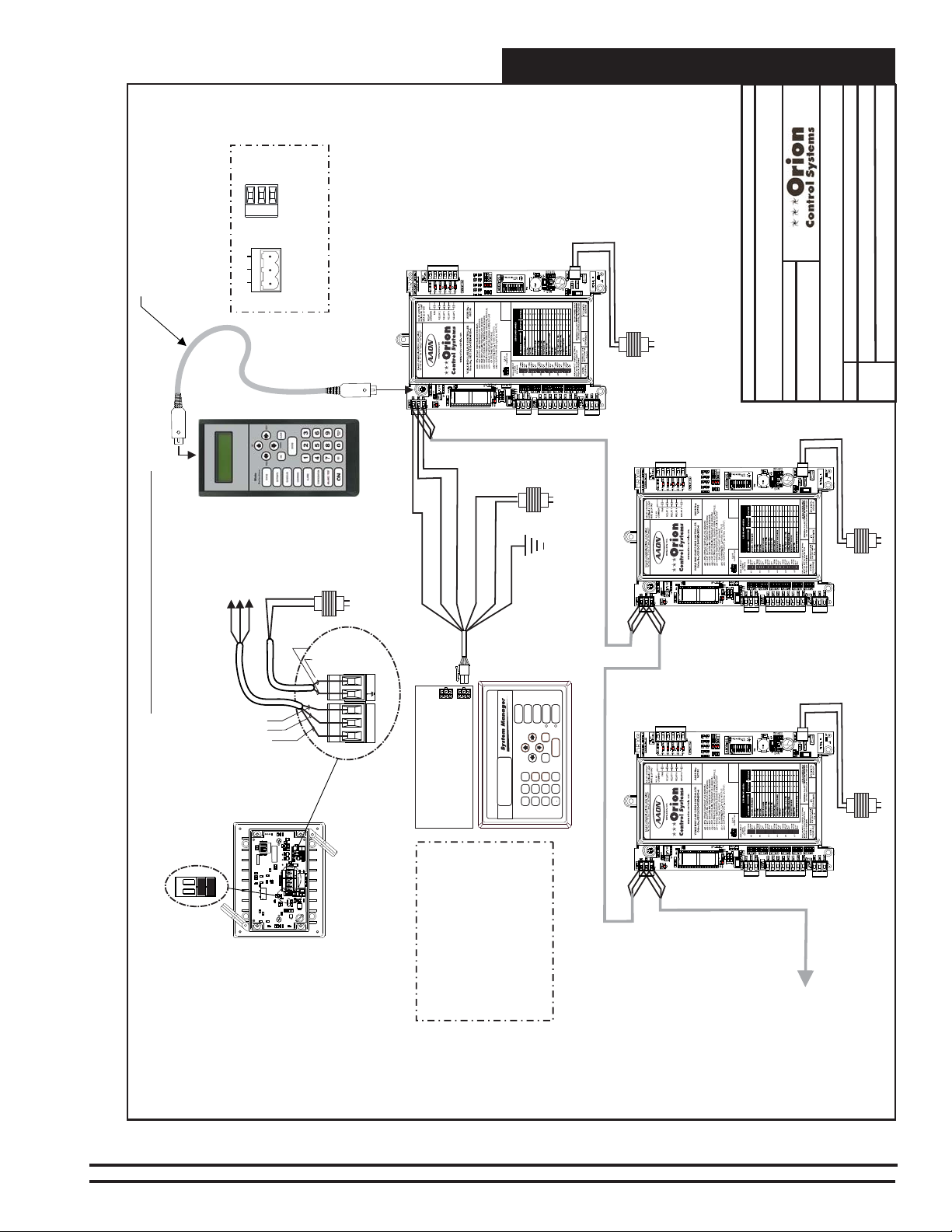
T
TERM
SHLD
R
Interconnected System
Connect MIni Din
Connector
Cable Ends To Female
Connectors on
Modular Service Tool
And VCM-X Controller
R
G
T
T, R & S
Connect To
Terminals On
485 LOOP
VCM-X
Controller
Typical Terminal Blocks. All
Wiring To Be T To T, SHLD (G)
To SHLD (G) & R To R
S. Olson
BY:
WARNING
OBSERVE
POLARITY
24 VAC
(8 VA)
JOB NAME
FILENAME
DESCRIPTION:
05/12/15
Wiring & Connection Diagram
VCM-X E-BUS Interconnected System
DATE:
VCM-X E-BUS Unit Controller
1 of 1
PAGE
O-VCMX-Sys-InterConnect-1A.CDR
Line Voltage
WARNING
OBSERVE
Tool SD
Modular Service
24 VAC
(6 VA)
DRAIN WIRE (SHLD)
WHITE (T)
RED (24 VAC)
BLACK (R)
24 VAC
(6 VA)
GREEN (GND)
CLEAR (GND)
Line Voltage
VCM-X E-BUS Unit Controller
Line Voltage
BROWN (GND)
RED (24 VAC)
POLARITY
24 VAC
(8 VA)
Line VoltageLine Voltage
Typical Interconnected System
For Stand Alone Applications
Both Jumpers Must Be ON
WHITE (T)
BARE (S)
BLACK (R)
R
T
5V
GND
R34 R16
1002 1002
SW1
OPT4
OPT3
OPT2
OFF
OPT1
1002 1002
R13R8
MADE IN USA
YS102178 R4
WQVGAGraphical Interface
WattMaster Controls, Inc
YS102178 R4
WQVGAGraphical Interface
WattMaster Controls, Inc
C7
C7
.1uF
C9
C9
.1uF
.1uF
C10
C10
C15
C15
.1uF
.1uF
C12
C12
C11
C11
.1uF
R1
R1
R7
R7
C1
1002
C1
1002
1002
.1uF
C13
C13
.1uF
.1uF
C14
C14
66.000Mhz
X3
X3
C20
C20
C23
.1uF
1002
R20
C26
C25
.1uF
.1uF
.1uF
R10
1002
1002
1002
1002
R41
R39
R21
R23
1002
C41
.1uF
L4
D11
R35
1002
1002
U13
L1
C36
.1uF
1002
1002
R32R31
U11
Q2
.1uF
R18
C34 C40
SERIAL#
.1uF
1002
.1uF
C29
R15
U10
C27
.1uF
C28
.1uF
1002
R2
R2
1002
5V 3.3V 2.5V
D1
V1
R5
R5
1002
R6
R6
1002
R9
R9
J1
C16
C18
1002
1002
TERM
1002
.1uF
.1uF
.1uF
C19
C19
J3
R46
R43
R47
.1uF
C17
8.00Mhz
.1uF
.1uF
.1uF
C5 C4
C50
.1uF
X2
C8
C6
R26
R17
C45
R40
R42
.1uF
1002
1002
1002
1002
1002
R14
1002
R36
RTC
CAL
R27
R24
R22
R12
1002
1002
1002
1002
1002
R29
Figure 4: Interconnected System Wiring
STATUS
ALARMS
SETPOINTS
OVERRIDES
SCHEDULES
RS T +
Connect To Modular
I/O Connectors
Located On Back
Of The System Manager
C35
C2C3
.1uF
D2
1002
C30
.1uF
1002 1002
1002
.1uF
1002
U9
.1uF
LTC3824
1002
C32 R30
R28
R33
R19
C31
R11
R25
C24
C24
330uF 50V 330uF
RST +
R48
1002
R45
1002
1002
1002
R49
R44
D12
.1uF
1002
R37
C51
C51
L5
C39
C39
(Back Side Shown)
System Manager TS II
Note: Either A Modular System
Manager SD, System Manager TS
II, Modular Service Tool SD Or PC
With Prism 2 Software Installed
Can Be Used To Program And
NEXT
CLEAR
UP
DOWN
ENTER
ESC
PREV
9
6
-
MINUS
0
8
2
5
13
7
4
DEC
(Front Side Shown)
VCM-X E-BUS Unit Controller
Modular System Manager SD
Configure The Orion System. For
Computer & Remote Connection
Information, See The Computer
Connection Section Of This
Manual.
WARNING
OBSERVE
POLARITY
To Next HVAC Unit
Controller On Loop
Up To 60 Controllers
Can Be Interconnected
24 VAC
(8 VA)
VCM-X Component & Systems Wiring
23
Page 24

Networked Single Loop System
TERM
WARNING
OBSERVE
POLARITY
24 VAC
(8 VA)
VCM-X E-BUS Unit Controller
VCM-X E-BUS Unit Controller
Line Voltage
Zone
Zone
WARNING
OBSERVE
POLARITY
24 VAC
(8 VA)
S. Olson
BY:
Line Voltage
JOB NAME
DESCRIPTION:
DRAIN WIRE (SHLD)
WHITE (T)
RED (24 VAC)
BLACK (R)
TB1
Connect To Modular
I/O Connectors
Located On Back
Of The System Manager
T, R & S
VCM-X Or
Connect To
Terminals On
24 VAC
(6 VA)
GREEN (GND)
CLEAR (GND)
STATUS
SETPOINTS
SCHEDULES
NEXT
UP
PREV
6
2
5
13
4
VAV/Zone
Controller
Line Voltage
ALARMS
OVERRIDES
CLEAR
DOWN
ENTER
ESC
9
-
MINUS
0
8
7
DEC
24 VAC
(6 VA)
SHLD
T
R
485 LOOP
R
G
T
Typical Terminal Blocks. All
Wiring To Be T To T, SHLD (G)
Manager SD
Modular System
05/12/15
FILENAME
DATE:
O-VCMX-Network-SingleLoop1A.CDR
WARNING
OBSERVE
POLARITY
Wiring & Connection Diagrams
VCM-X E-BUS Networked System - Single Loop
PAGE
1 of 5
To SHLD (G) & R To R
24 VAC
Connect MIni Din Connector
Cable Ends To Female
Connectors on Modular
Service Tool And VCM-X
E-BUS Controller
VCM-X E-BUS Unit Controller
(8 VA)
Line VoltageLine Voltage
Tool SD
Modular Service
WARNING
OBSERVE
POLARITY
24 VAC
(8 VA)
Line Voltage
BROWN (GND)
RED (24 VAC)
Note: Either A Modular System
Manager SD, System Manager TS II,
Modular Service Tool SD Or PC With
Prism 2 Software Installed Can Be
Used To Program And Configure The
Orion System. For Computer And
Remote Connection Information, See
The Computer Connection Section Of
This Manual.
WHITE (T)
BARE (S)
BLACK (R)
RS T +
Serial #
Typical Single Loop Networked System With CommLink 5 Only
1002
1002
1002
R
T
R41
5V
GND
R39
R21
R23
1002
R34 R16
C41
1002 1002
.1uF
L4
D11
C35
C2C3
SW1
OPT4
.1uF
R35
OPT3
1002
1002
U13
L1
C36
OPT2
OFF
.1uF
1002
1002
OPT1
R32R31
D2
1002
Q2
U11
1002 1002
C30
.1uF
.1uF
R13R8
R18
1002 1002
1002
.1uF
1002
U9
C34 C40
SERIAL#
.1uF
1002
.1uF
.1uF
C29
R15
LTC3824
1002
U10
C27
.1uF
C28
C32 R30
.1uF
R28
For All Applications With
CommLink(s) Or MiniLink(s),
Both Jumpers Must Be OFF.
WQVGAGraphical Interface
WattMaster Controls, Inc
WQVGAGraphical Interface
WattMaster Controls, Inc
C9
C9
.1uF
C10
C10
.1uF
C11
C11
.1uF
C13
C13
.1uF
Figure 5: Networked Single Loop System With CommLink Only Wiring
R33
R19
MADE IN USA
YS102178 R4
YS102178 R4
C31
1002
R2
R2
1002
R11
5V 3.3V 2.5V
D1
R25
V1
R5
R5
1002
R6
R6
1002
C7
C7
.1uF
C24
C24
.1uF
C15
C15
.1uF
C12
C12
R1
R1
R7
R7
R9
R9
C1
1002
C1
1002
1002
.1uF
.1uF
C14
C14
330uF 50V 330uF
J1
RST +
R48
1002
R45
C16
C18
1002
1002
1002
TERM
1002
1002
1002
66.000Mhz
.1uF
.1uF
.1uF
C19
C19
R49
R44
J3
R46
R43
R47
.1uF
D12
X3
X3
C17
8.00Mhz
.1uF
1002
R37
.1uF
.1uF
C20
C20
C51
C51
.1uF
C5 C4
C50
.1uF
X2
C8
L5
C6
R26
R17
C45
R40
R42
.1uF
1002
1002
1002
1002
1002
C23
.1uF
1002
R14
1002
R36
R20
C39
C39
RTC
CAL
C26
C25
.1uF
.1uF
.1uF
R27
R24
R22
R12
R10
1002
1002
1002
1002
1002
1002
R29
System Manager TS II
Note: The System Manager TS II Wiring
Is Typical For All System Types And
Configurations. It Is Shown On This Page
CommLink 5
Only To Conserve Space.
Front View
10/100
24
110 VAC To
24V
GND
POWER
T(-)
SHLD
R (+)
485 LOOP
LOW
HIGH
BAUD
USB
COMPUTER
SINGLE
MULTIPLE
Back View
LOOP
ACT LNK
ETHERNET
DIAG
VCM-X Component & Systems Wiring
24 VAC
Power Pack
VCM-X E-BUS Unit Controller
Note: CommLink Must Be
Set For Multiple Loop
Operation When Used With
A MiniLink Whether It Is A
Single Loop System Or Not.
If it Doesn’t Have A MiniLink
Set It To Single Loop.
To Next HVAC Unit
Controller On Loop
Up To 60 Controllers
Can Be Interconnected
Page 25

VCM-X E-BUS
O
O
O
Unit Controller
Line Voltage
Tool SD
Modular Service
24 VAC
(8 VA)
WARNING
OBSERVE
POLARITY
Networked Single Loop System
Connect To Next
VAV/Zone Controller
(Modular)
VAV/Zone
Controller
On Branch Circuit
www.orioncontrols.com
OE744-31-VAVZ
P.I. VAV/ZONE
CONTROLLERACTUATOR
PACKAGE
OE282
REC
POWER/CO
MM
10
JOB NAME
FILENAME
S. Olson
BY:
DESCRIPTION:
05/12/15
DATE:
VCM-X E-BUS Networked System - Single Loop
Wiring & Connection Diagrams
T
SHLD
R
C1
TB1
T
SHLD
R
COMMPIN
P2
485 LOOP
TB2
Board
24
VAC
25
Transformer
24 VAC - Size
R
G
T
Typical Terminal Blocks. All
Wiring To Be T To T, SHLD (G)
To SHLD (G) & R To R
Power/Comm
P5
M
ER & COM
POW
ARD
DIST. BO
P4
YS101856
REV. 0
ER
POW
LD1
4A
F1
POWER & COMM
OUT
P3
R1
V1
D1
P1
For Required VA Load
Line Voltage
Connect To Modular
I/O Connectors
Located On Back
C
3
X1
YS101900PMINILINK
POLLING
DEVICE
REV. 1
C
X
6
U6
U10
D
1
U6
U1
C2
PHILIPS
CX1
C3
C1
1
R
1
CX5
U5
U4
C
X
2
R
4
LED 1
LED 2
Of The System Manager
C10
R30X2R29
R28
U11
C9
RN2
RN3
P3
R
24
LD4
U
14
CX6
WDOG
NETWORK
DRIVER
C
X
14
NETWORK
LOOP
R2
U
13
LD5
LD
LOOP
DRIVER
C
X13
U
15
PROC.
DRIVER
U2
LOCALLOOP
C
X15
LD6
0-10V
THERM
4-20mA
C
X
2
AIN2
RAM
OFF=0-5V
C8
AIN1
0-10V
THERM
4-20mA
R
27
C7
EPROM
D
U12
C
R
25
R
26
R
31
V1
POWER
Note: For System
Manager TS II Wiring,
See Figure 3.
Typical Single Loop Networked System
Note: Either A Modular System Manager SD,
System Manager TS II, Modular Service Tool
SD Or PC With Prism 2 Software Installed Can
Be Used To Program And Configure The Orion
System. For Computer And Remote
Connection Information, See The Computer
With MiniLink Polling Device & Modular VAV/Zone Controllers
Connection Section Of This Manual.
System Manager TS II
C
1
R
3
CX7
U7
C
X
1
U1
C4
P1
X1
YS101818P552
PROCESSORPBOARD
MiniLink PD
CX4
CX3
U3
RV1
V
R
EF
LD
D
2
1
N
4
32
16
8
4
2
1
R
T
R
H
S
T
P4
N
G
IN
A
IN
A
+5V
G
24VA
D
OFF
AD
D
P5
SH
4
3
TB
2
C11
D5
TB
1
STATUS
SW1
TB
TB
Connect To
SETPOINTS
SCHEDULES
NEXT
CLEAR
UP
ESC
PREV
6
2
5
13
4
Local
On Loop
Controllers
Other VAV/Zone
ALARMS
OVERRIDES
DOWN
ENTER
9
-
MINUS
0
8
7
DEC
On Loop
Controllers
Connect To
Other VAV/Zone
Board
Power/Comm
Manager SD
Modular System
Line Voltage
Local
C1
TB1
T
SHLD
POW
R
DIST. BOARD
YS101856
REV. 0
COMMPIN
P2
ER
POW
LD1
TB2
24
VAC
4A
25
F1
Transformer
24 VAC - Size
For Required VA Load
O-VCMX-Network-SingleLoop1A.CDR
www.orioncontrols.com
OE744-31-VAVZ
P.I. VAV/ZONE
CONTROLLERACTUATOR
PACKAGE
(Modular)
VAV/Zone
Controller
REC
POWER/CO
MM
P5
M
ER & COM
P4
POWER & COMM
OUT
P3
R1
V1
D1
P1
On Loop
Controllers
Connect To
Other VAV/Zone
www.orioncontrols.com
OE744-31-VAVZ
P.I. VAV/ZONE
(Modular)
VAV/Zone
Controller
CONTROLLERACTUATOR
REC
POWER/CO
MM
OE282
Note: A Maximum Of 6 VAV/Zone Controllers Can Be
Connected To Each Branch Circuit. A total Of 16
Controllers Are Allowed Per Power/Comm Board. Use
PACKAGE
OE282
2 of 5
PAGE
10
Additional Power/Comm Boards For Systems That
Exceed 16 Controllers. See The VAV/Zone Controller
Wiring Diagram For Power/Comm Board Transformer
Sizing And Circuit Design Information.
10
24 VAC
(6 VA)
Figure 6: Networked Single Loop System With MiniLink PD And Modular VAV/Zone Controllers Wiring
VCM-X Component & Systems Wiring
Connect To Next
VAV/Zone Controller
On Branch Circuit
25
Page 26

Networked Single Loop System
Line Voltage
Tool SD
Modular Service
VCM-X E-BUS
Unit Controller
SHLD
T
R
485 LOOP
R
G
T
Typical Terminal Blocks. All
Wiring To Be T To T, SHLD (G)
To SHLD (G) & R To R
24 VAC
24 VAC
(8 VA)
WARNING
OBSERVE
POLARITY
(6 VA)
Line Voltage
VAV/Zone
Controller
(Non-Modular)
Line
Voltage
Zone
TB2
REC
T
SHLD
R
24VAC
GND
TB3
STAT
24 VAC
(6 VA)
Zone
S. Olson
BY:
www.orioncontrols.com
OE744-32-VAVZ
P.I. VAV/ZONE
CONTROLLERACTUATOR
PACKAGE
T
SHLD
R
24 VAC
GND
OE282
VAV/Zone
Controller
(Non-Modular)
10
TB2
REC
T
SHLD
R
24VAC
GND
TB3
STAT
JOB NAME
FILENAME
www.orioncontrols.com
OE744-32-VAVZ
P.I. VAV/ZONE
CONTROLLERACTUATOR
PACKAGE
T
SHLD
R
24 VAC
GND
DESCRIPTION:
05/12/15
DATE:
O-VCMX-Network-SingleLoop1A.CDR
OE282
Wiring & Connection Diagrams
VCM-X E-BUS Networked System - Single Loop
3 of 5
PAGE
10
DRAIN WIRE (SHLD)
WHITE (T)
BLACK (R)
Note: For System
Manager TS II Wiring,
See Figure 3.
System Manager TS II
Connect To Modular
I/O Connectors
C3
C
1
X
1
R
3
CX7
U7
C
X
6
C
X
1
U1
C4
P1
C2
X1
YS101818P552
PROCESSORPBOARD
Typical Single Loop Networked System
Note: Either A Modular System Manager SD,
System Manager TS II, Modular Service Tool
SD Or PC With Prism 2 Software Installed Can
Be Used To Program And Configure The Orion
System. For Computer And Remote
Connection Information, See The Computer
Connection Section Of This Manual.
C1
CX5
U5
MiniLink PD
CX4
U4
CX3
U3
C
X
2
RV1
R
4
V
R
E
F
With MiniLink Polling Device & Non-Modular VAV/Zone Controllers
GREEN (GND)
RED (24 VAC)
CLEAR (GND)
STATUS
UP
Located On Back
Of The System Manager
C10
R30X2R29
R28
OFF
32
U11
C9
YS101900PMINILINK
POLLING
DEVICE
REV. 1
U6
U10
D
1
U1
PHILIPS
1
1
LED 1
LED 2
16
8
4
2
RN2
1
RN3
A
D
D
P3
5
P
R
24
LD4
U6
CX1
C3
R
R
U
14
CX6
LD
SH
WDOG
T
NETWORK
DRIVER
C
X
14
4
TB
NETWORK
LOOP
R2
3
TB
U
13
LD5
R
LD
SH
LOOP
DRIVER
T
C
X13
U
15
PROC.
DRIVER
U2
LOCALLOOP
C
X
15
LD6
P4
D
N
G
0-10V
THERM
4-20mA
C
X
2
IN
2
A
AIN2
1
AIN
RAM
OFF=0-5V
C8
+5V
AIN1
TB
2
0-10V
THERM
4-20mA
R
27
C11
D5
C7
EPROM
D
N
G
U12
C
24VA
R
25
R
26
TB
1
D
4
R
31
V
1
POWER
24 VAC
(6 VA)
ALARMS
SETPOINTS
OVERRIDES
SCHEDULES
NEXT
CLEAR
DOWN
ENTER
ESC
PREV
9
6
MINUS
0
8
2
5
13
7
4
DEC
SW1
VAV/Zone
Controller
-
Modular System Manager SD
Local
Local
Note: Multiple VAV/Zone
Controllers Can Be Connected To
A Single Transformer If Desired.
However Polarity Must Be
Observed Or Damage To The
(Non-Modular)
T
SHLD
TB2
R
REC
T
24 VAC
SHLD
GND
R
24VAC
GND
TB3
STAT
24 VAC
(6 VA)
Line
Voltage
Controller(s) Will Result. See The
Non-Modular Transformer Sizing
Page In This Manual For
Transformer Sizing And Circuit
Design Information.
www.orioncontrols.com
OE744-32-VAVZ
P.I. VAV/ZONE
CONTROLLERACTUATOR
PACKAGE
VAV/Zone
24 VAC
(6 VA)
Line
Voltage
OE282
Controller
(Non-Modular)
TB2
REC
T
SHLD
R
24VAC
GND
TB3
STAT
24 VAC
(6 VA)
Line
Voltage
10
Note: Multiple VAV/Zone Controllers Can Be Connected
To A Single Transformer If Desired. However Polarity
Must Be Observed Or Damage To The Controller(s) Will
Result. See The Non- Modular Transformer Sizing Page
In This Manual For Transformer Sizing And Circuit
Design Information.
www.orioncontrols.com
OE744-32-VAVZ
P.I. VAV/ZONE
CONTROLLERACTUATOR
PACKAGE
T
SHLD
R
24 VAC
GND
OE282
Connect To Next
10
VAV/Zone Controller
On Local Loop
Figure 7: Networked Single Loop System With MiniLink PD And Non Modular VAV/Zone Controllers Wiring
26
VCM-X Component & Systems Wiring
Page 27

O
O
VCM-X E-BUS
Unit Controller
Line Voltage
Tool SD
Modular Service
24 VAC
(8 VA)
WARNING
OBSERVE
POLARITY
Networked Single Loop System
Connect To Next
VAV/Zone Controller
VAV/Zone
Controller
On Branch Circuit
www.orioncontrols.com
OE744-31-VAVZ
P.I. VAV/ZONE
CONTROLLERACTUATOR
PACKAGE
REC
POWER/CO
MM
10
OE282
JOB NAME
FILENAME
S. Olson
BY:
DESCRIPTION:
05/12/15
VCM-X Networked System - Single Loop
DATE:
Wiring & Connection Diagrams
SHLD
T
R
485 LOOP
R
G
T
Typical Terminal Blocks. All
Wiring To Be T To T, SHLD (G)
To SHLD (G) & R To R
Note: For System
Manager TS II Wiring,
See Figure 3.
Typical Single Loop Networked System With MiniLink
Polling Device, CommLink & Modular VAV/Zone Controllers
Note: Either A Modular System Manager SD,
System Manager TS II, Modular Service Tool
SD Or PC With Prism 2 Software Installed Can
Be Used To Program And Configure The Orion
System. For Computer And Remote
Board
Power/Comm
Line Voltage
Connection Information, See The Computer
Connection Section Of This Manual.
C1
TB1
T
SHLD
R
COMMPIN
P2
TB2
24
VAC
25
Transformer
24 VAC - Size
P5
MM
ER & CO
PO
W
DIST. BOARD
P4
YS101856
REV. 0
ER
POW
LD1
4A
F1
POWER & COMM
OUT
P3
R1
V1
D1
P1
For Required VA Load
System Manager TS II
Connect To Modular
I/O Connectors
Located On Back
Of The System Manager
Note: CommLink Must Be Set
For Multiple Loop Operation
When Used With A MiniLink
Whether It Is A Single Loop
System Or Not. If it Doesn’t
Have A MiniLink Set It To
Single Loop.
Connect To
Other VAV/Zone
STATUS
ALARMS
SETPOINTS
OVERRIDES
SCHEDULES
NEXT
CLEAR
UP
DOWN
ENTER
ESC
PREV
9
6
MINUS
8
2
5
13
7
4
DEC
110 VAC To
CommLink 5
On Loop
Controllers
-
Manager SD
0
Modular System
24 VAC
Power Pack
Serial #
24V
GND
T(-)
SHLD
R (+)
LOW
HIGH
USB
COMPUTER
SINGLE
MULTIPLE
Front View
10/100
ETHERNET
Connect To Next
VAV/Zone Controller
On Branch Circuit
On Loop
Controllers
Connect To
Other VAV/Zone
COMMPIN
Board
Power/Comm
24 VAC - Size
Line Voltage
POWER
485 LOOP
BAUD
Back View
LOOP
ACT LNK
DIAG
Note: See Computer &
VAV/Zone
Controller
C1
TB1
T
SHLD
R
P2
TB2
24
VAC
25
Transformer
P5
M
ER & COM
PO
W
DIST. BOARD
P4
YS101856
REV. 0
ER
PO
W
LD1
V1
4A
F1
R1
P3
D1
P1
Connect To
POWER & COMM
OUT
On Loop
Controllers
Other VAV/Zone
For Required VA Load
C
3
C1
X
1
R3
CX7
U7
C
X6
C
X1
U1
U6
C4
P1
C2
X1
YS101818P552
PROCESSORPBOARD
C1
CX5
U5
CX4
U4
MiniLink PD Loop 1
CX3
U3
C
X
2
RV1
R
4
V
R
E
F
LED 1
Accessories Connection Section
Of This Manual For Optional
Computer and Remote
Connection Diagrams.
O-VCMX-Net-SingleLoop1A.CDR
www.orioncontrols.com
OE744-31-VAVZ
P.I. VAV/ZONE
CONTROLLERACTUATOR
PACKAGE
OE282
REC
POWER/CO
MM
Note: A Maximum Of 6 VAV/Zone Controllers Can Be
Connected To Each Branch Circuit. A total Of 16
Controllers Are Allowed Per Power/Comm Board. Use
C10
R30X2R29
R28
OFF
SW1
32
U11
C9
YS101900PMINILINK
POLLING
DEVICE
REV. 1
U10
D
1
U6
U1
PHILIPS
CX1
C3
1
R
1
LED 2
16
8
4
2
RN2
1
RN3
AD
D
P3
P5
R
24
LD4
R
U14
CX6
LD
H
S
WDOG
T
NETWORK
DRIVER
C
X14
4
TB
NETWORK
LOOP
R2
3
TB
U
13
LD5
R
LD
H
S
LOOP
DRIVER
T
C
X
13
U
15
PROC.
DRIVER
U2
LOCALLOOP
C
X15
LD6
P4
D
N
G
0-10V
THERM
4-20mA
C
X
2
IN
2
A
AIN2
IN
1
A
RAM
OFF=0-5V
C8
+5V
AIN1
TB
2
0-10V
THERM
4-20mA
R
27
C11
D5
C7
EPROM
D
N
G
U12
C
24VA
R
25
R
26
TB1
D
4
R
31
V
1
POWER
24 VAC
(6 VA)
4 of 5
PAGE
10
Additional Power/Comm Boards For Systems That
Exceed 16 Controllers. See The VAV/Zone Controller
Wiring Diagram For Power/Comm Board Transformer
Sizing And Circuit Design Information.
Local
Network
Figure 8: Networked Single Loop System With CommLink & MiniLink PD - Modular VAV/Zone Controllers
VCM-X Component & Systems Wiring
27
Page 28
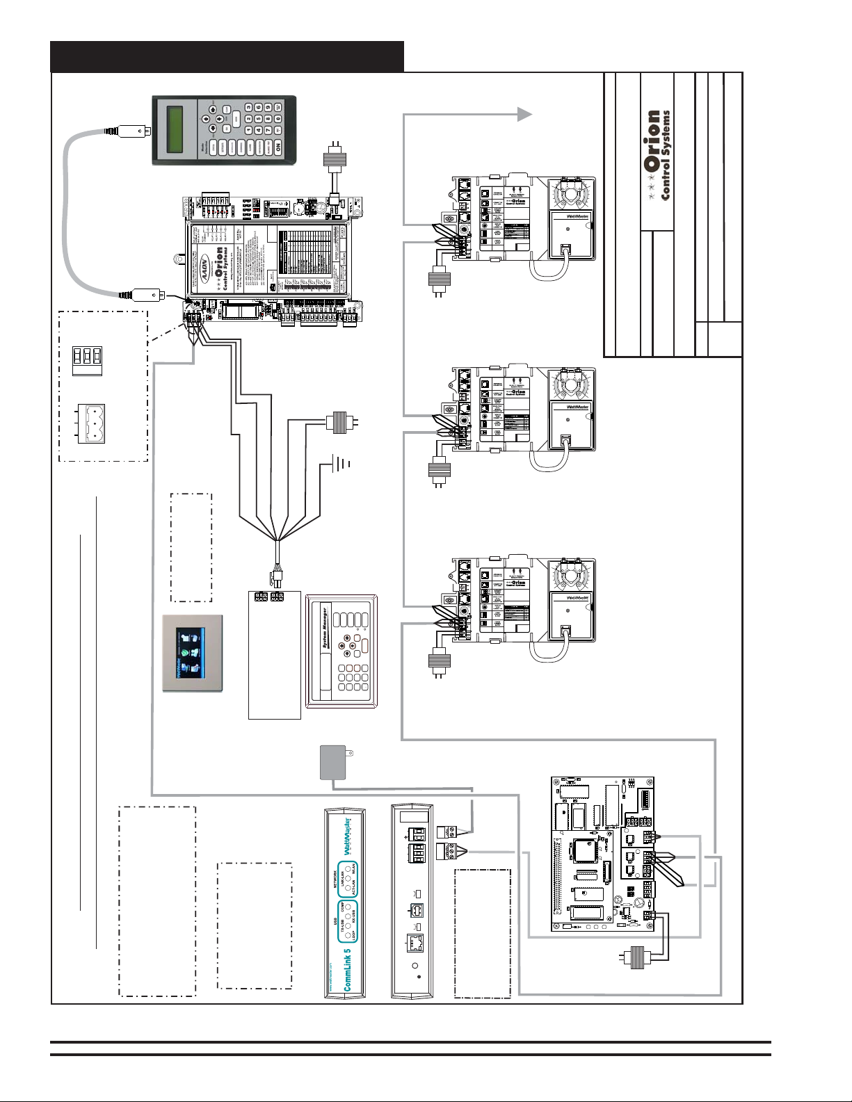
Networked Single Loop System
Line Voltage
Tool SD
T
SHLD
R
VCM-X E-BUS
Unit Controller
Modular Service
24 VAC
(8 VA)
WARNING
OBSERVE
POLARITY
VAV/Zone
Controller
(Non-Modular)
Line
Zone
TB2
T
SHLD
R
24VAC
TB3
24 VAC
Voltage
Zone
On Local Loop
Connect To Next
VAV/Zone Controller
S. Olson
www.orioncontrols.com
OE744-32-VAVZ
P.I. VAV/ZONE
CONTROLLERACTUATOR
PACKAGE
T
SHLD
R
REC
24 VAC
GND
GND
STAT
(6 VA)
10
OE282
JOB NAME
BY:
DESCRIPTION:
05/12/15
Wiring & Connection Diagrams
VCM-X Networked System - Single Loop
DATE:
FILENAME
PAGE
5 of 5
O-VCMX-Net-SingleLoop1A.CDR
485 LOOP
R
G
T
Typical Terminal Blocks. All
Wiring To Be T To T, SHLD (G)
To SHLD (G) & R To R
Typical Single Loop Networked System With MiniLink
Polling Device, CommLink & Non-Modular VAV/Zone Controllers
Note: Either A Modular System Manager SD,
System Manager TS II, Modular Service Tool
SD Or PC With Prism 2 Software Installed Can
Be Used To Program And Configure The Orion
System. For Computer And Remote
Note: For System
Manager TS II Wiring,
See Figure 3.
Connection Information, See The Computer
Connection Section Of This Manual.
24 VAC
DRAIN WIRE (SHLD)
WHITE (T)
System Manager TS II
Note: CommLink Must Be Set
For Multiple Loop Operation
RED (24 VAC)
CLEAR (GND)
BLACK (R)
TB1
Connect To Modular
I/O Connectors
Located On Back
Of The System Manager
When Used With A MiniLink
Whether It Is A Single Loop
System Or Not. If it Doesn’t
Have A MiniLink Set It To
Single Loop.
(6 VA)
GREEN (GND)
STATUS
ALARMS
SETPOINTS
OVERRIDES
SCHEDULES
NEXT
CLEAR
UP
DOWN
ENTER
ESC
PREV
6
9
-
MINUS
0
8
2
5
13
7
4
DEC
110 VAC To
CommLink 5
VAV/Zone
Controller
(Non-Modular)
TB2
REC
T
SHLD
R
24VAC
Line Voltage
VAV/Zone
Modular System Manager SD
24 VAC
Power Pack
Serial #
24V
GND
T(-)
SHLD
R (+)
LOW
HIGH
BAUD
USB
COMPUTER
SINGLE
MULTIPLE
Front View
10/100
LOOP
ETHERNET
DIAG
GND
TB3
STAT
24 VAC
Line
Voltage
Controller
(Non-Modular)
TB2
REC
T
SHLD
R
24VAC
GND
TB3
STAT
24 VAC
Line
Voltage
POWER
485 LOOP
Back View
ACT LNK
Note: See Computer &
(6 VA)
(6 VA)
Accessories Connection Section
www.orioncontrols.com
OE744-32-VAVZ
P.I. VAV/ZONE
CONTROLLERACTUATOR
PACKAGE
T
SHLD
R
24 VAC
GND
www.orioncontrols.com
OE744-32-VAVZ
P.I. VAV/ZONE
CONTROLLERACTUATOR
T
SHLD
R
24 VAC
GND
Of This Manual For Optional
Computer and Remote
Connection Diagrams.
OE282
PACKAGE
OE282
CX7
U7
U1
MiniLink PD Loop 1
C1
R3
C
X1
C4
P1
X1
YS101818P552
PROCESSORPBOARD
CX4
CX3
U3
RV1
V
R
E
F
10
10
Note: Multiple VAV/Zone Controllers Can Be Connected
To A Single Transformer If Desired. However Polarity
Must Be Observed Or Damage To The Controller(s) Will
Result. See The Non- Modular Transformer Sizing Page
In This Manual For Transformer Sizing And Circuit
Design Information.
C
3
X
1
X
6
C2
C1
CX5
U5
U4
C
X2
R
4
C10
R30X2R29
R28
OFF
SW1
32
U11
C9
YS101900PMINILINK
POLLING
DEVICE
REV. 1
C
U6
U10
D
1
U1
PHILIPS
1
1
LED 1
LED 2
16
8
4
2
RN2
1
RN3
A
D
D
3
P
5
P
R
24
LD4
U6
CX1
C3
R
R
U
14
CX6
LD
H
S
WDOG
T
NETWORK
DRIVER
C
X
14
4
TB
NETWORK
LOOP
R2
3
TB
U
13
LD5
R
LD
SH
LOOP
DRIVER
T
C
X13
U
15
PROC.
DRIVER
U2
LOCALLOOP
C
X
15
LD6
P4
D
N
G
0-10V
THERM
4-20mA
C
X2
IN
2
A
AIN2
IN
1
A
RAM
OFF=0-5V
C8
+5V
AIN1
TB
2
0-10V
THERM
4-20mA
R
27
C11
D5
C7
EPROM
D
N
G
U12
C
24VA
R
25
R
26
TB
1
D
4
R
31
V
1
POWER
24 VAC
(6 VA)
Local
Local
Network
Figure 9: Networked Single Loop System With CommLink & MLPD - Non-Modular VAV/Zone Controllers
28
VCM-X Component & Systems Wiring
Page 29

Networked Multiple Loop System Connections & Wiring
O
O
Tool SD
Line Voltage
Modular Service
Connect To Next
VAV/Zone Controller
On Branch Circuit
10
OE282
JOB NAME
Controller
VCM-X E-BUS
24 VAC
(8 VA)
WARNING
OBSERVE
POLARITY
VAV/Zone
Controller
www.orioncontrols.com
OE744-31-VAVZ
P.I. VAV/ZONE
CONTROLLERACTUATOR
PACKAGE
REC
POWER/CO
MM
Line Voltage
SHLD
T
R
C1
TB1
T
SHLD
R
Board
COMMPIN
P2
TB2
24
VAC
25
485 LOOP
R
G
T
Typical Terminal Blocks. All
Wiring To Be T To T, SHLD (G)
To SHLD (G) & R To R
P5
ER & COMM
POW
DIST. BOARD
P4
YS101856
REV. 0
ER
POW
LD1
4A
F1
POWER & COMM
OUT
P3
R1
V1
D1
P1
Power/Comm
www.orioncontrols.com
OE744-31-VAVZ
P.I. VAV/ZONE
CONTROLLERACTUATOR
VAV/Zone
Controller
REC
POWER/CO
MM
PACKAGE
S. Olson
BY:
DESCRIPTION:
Networked System - Multiple Loop
05/07/15
FILENAME
DATE:
1 of 2
PAGE
O-VCMX-Net-MultiLoop-1A.CDR
10
OE282
Wiring & Connection Diagram
24 VAC
110 VAC To
Power Pack
Front View of CommLink 5
Typ. Multiple Loop Networked System With Modular VAV/Zone Controllers
Note: Either A Modular System Manager SD,
System Manager TS II, Modular Service Tool
SD Or PC With Prism 2 Software Installed Can
Be Used To Program And Configure The Orion
System. For Computer & IP Module
Connection Information See The Computer
Connection Section Of This Manual.
Line Voltage
Transformer
24 VAC - Size
For Required VA Load
TB1
Connect To Modular
I/O Connectors
Located On Back
Of The System Manager
Serial #
24V
GND
POWER
T(-)
SHLD
R(+)
485 LOOP
LOW
HIGH
BAUD
USB
COMPUTER
SINGLE
MULTIPLE
LOOP
10/100
ACT LNK
ETHERNET
Back View of CommLink 5
DIAG
On Loop
Controllers
Connect To
Other VAV/Zone
STATUS
ALARMS
SETPOINTS
OVERRIDES
SCHEDULES
NEXT
CLEAR
UP
DOWN
ENTER
ESC
PREV
9
6
-
MINUS
0
8
2
5
13
7
4
DEC
Modular System Manager SD
C
1
R3
CX7
U7
C
X
1
U1
C4
P1
X1
YS101818P552
PROCESSORPBOARD
CX4
MiniLink PD Loop 1
CX3
U3
RV1
VR
EF
Note: CommLink Must Be Set
For Multiple Loop Operation
Connect To
Other VAV/Zone
Power/Comm
Line Voltage
C3
X1
YS101900PMINILINK
POLLING
DEVICE
REV. 1
C
X
6
U6
U10
D
1
U6
U1
C2
PHILIPS
CX1
C3
C1
1
R
1
CX5
U5
U4
C
X
2
R
4
LED 1
LED 2
On Loop
Controllers
TB1
COMMPIN
P2
TB2
Board
24 VAC - Size
C10
R30X2R29
R28
U11
C9
RN2
RN3
3
P
R
24
LD4
U14
CX6
LD
WDOG
NETWORK
DRIVER
C
X
14
NETWORK
LOOP
R2
U
13
LD5
LD
LOOP
DRIVER
C
X
13
U
15
PROC.
DRIVER
U2
LOCALLOOP
C
X
15
LD6
D
0-10V
THERM
4-20mA
C
X
2
2
AIN2
1
RAM
OFF=0-5V
C8
AIN1
0-10V
THERM
4-20mA
R
27
C7
EPROM
D
U12
C
R
25
R
26
4
R
31
V
1
POWER
24 VAC
(6 VA)
C1
T
SHLD
M
ER & COM
POW
R
ARD
DIST. BO
YS101856
REV. 0
R1
ER
PO
W
LD1
V1
24
VAC
4A
25
F1
Transformer
For Required VA Load
OFF
SW1
32
16
8
4
2
1
AD
D
5
P
R
H
S
T
4
TB
3
TB
R
SH
T
P4
N
G
AIN
IN
A
+5V
TB2
C11
D5
N
G
24VA
TB
1
D
P5
P4
POWER & COMM
OUT
P3
D1
P1
Connect To
Other VAV/Zone
Local
Network
Local
On Loop
Controllers
C3
C
1
X1
R3
Network
CX7
U7
C
X6
C
X
1
U1
U6
C4
P1
C2
X1
YS101818P552
PROCESSORPBOARD
C1
CX5
U5
CX4
U4
MiniLink PD Loop 2
CX3
U3
C
X
2
RV1
R
4
V
R
E
F
LED 1
U11
YS101900PMINILINK
POLLING
DEVICE
REV. 1
RN2
U10
R
24
D
1
U6
CX6
U1
WDOG
PHILIPS
R2
CX1
C3
1
R
1
U2
C
X2
RAM
C8
C7
EPROM
R
25
R
26
POWER
LED 2
24 VAC
(6 VA)
Note: A Maximum Of 6 VAV/Zone Controllers
Can Be Connected To Each Branch Circuit. A total
Of 16 Controllers Are Allowed Per Power/Comm
Board. Use Additional Power/Comm Boards For
Systems That Exceed 16 Controllers. See The
VAV/Zone Controller Wiring Diagram For
MiniLink PD
Connect To Loop 3
C10
R30X2R29
R28
OFF
SW1
32
C9
16
8
4
2
1
RN3
A
D
D
3
P
5
P
LD4
R
U14
LD
H
S
T
NETWORK
DRIVER
C
X14
4
TB
NETWORK
LOOP
3
TB
U
13
LD5
R
LD
SH
LOOP
DRIVER
T
C
X13
U
15
PROC.
DRIVER
LOCALLOOP
C
X15
LD6
P4
D
N
G
0-10V
THERM
4-20mA
IN
2
A
AIN2
IN
1
A
OFF=0-5V
+5V
AIN1
TB
2
0-10V
THERM
4-20mA
R
27
C11
D5
D
N
G
U12
C
24VA
TB
1
D
4
R
31
V
1
Connect To Loop 2
Power/Comm
Power/Comm Board Transformer Sizing And
Circuit Design Information.
Board & VCM-X
Controller
Figure 10: Networked Multiple Loop System Wiring With Modular VAV/Zone Controllers
VCM-X Component & Systems Wiring
29
Page 30
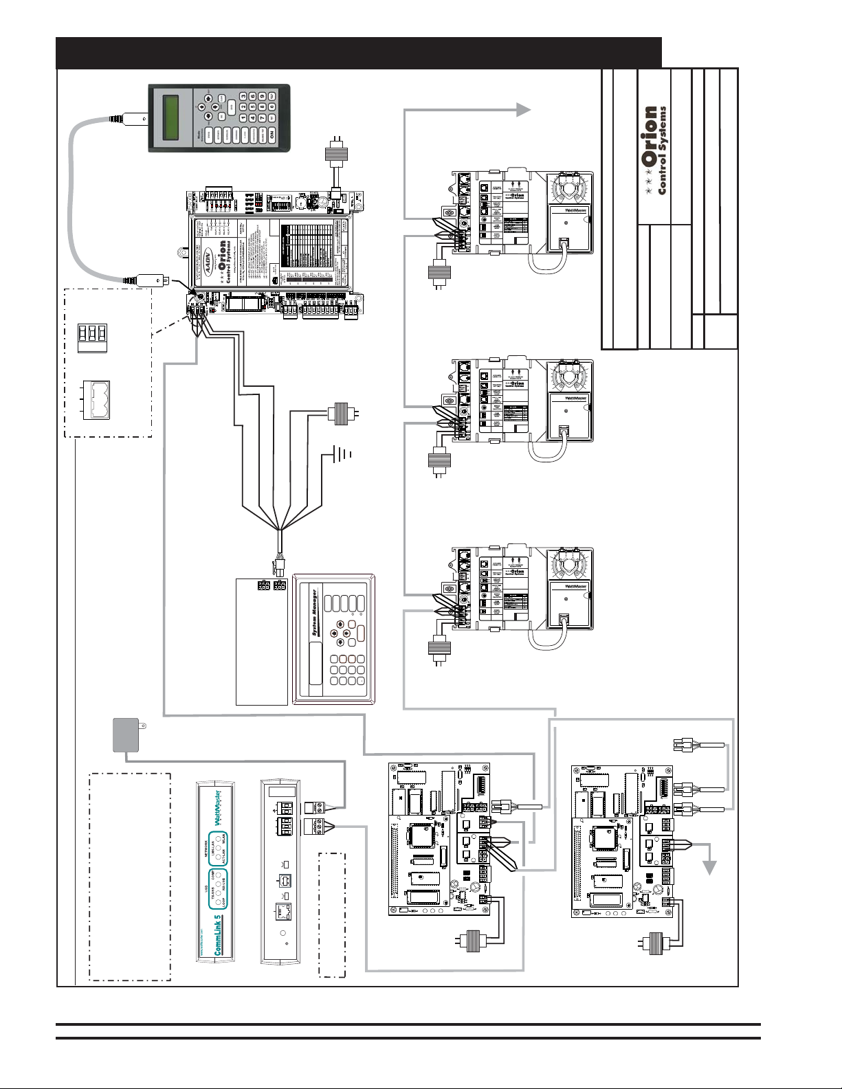
Zone
Networked Multiple Loop System Connections & Wiring
Tool SD
Line Voltage
Modular Service
24 VAC
(8 VA)
WARNING
OBSERVE
POLARITY
Controller
VCM-X E-BUS
SHLD
T
R
485 LOOP
R
G
T
Typical Terminal Blocks. All
Wiring To Be T To T, SHLD (G)
To SHLD (G) & R To R
24 VAC
(6 VA)
Line Voltage
VAV/Zone
Controller
(Non-Modular)
Line
VAV/Zone
Controller
(Non-Modular)
TB2
T
SHLD
R
24VAC
GND
TB3
STAT
24 VAC
Voltage
TB2
T
SHLD
R
24VAC
GND
TB3
STAT
T
SHLD
R
REC
24 VAC
GND
(6 VA)
T
SHLD
R
REC
24 VAC
GND
www.orioncontrols.com
OE744-32-VAVZ
P.I. VAV/ZONE
CONTROLLERACTUATOR
PACKAGE
www.orioncontrols.com
OE744-32-VAVZ
P.I. VAV/ZONE
CONTROLLERACTUATOR
PACKAGE
Zone
Connect To Next
VAV/Zone Controller
OE282
OE282
On Local Loop
10
JOB NAME
10
S. Olson
BY:
DESCRIPTION:
Networked System - Multiple Loop
05/07/15
FILENAME
DATE:
2 of 2
PAGE
O-VCMX-Net-MultiLoop-1A.CDR
Wiring & Connection Diagram
24 VAC
110 VAC To
Power Pack
Front View of CommLink 5
Note: Either A Modular System Manager SD,
System Manager TS II, Modular Service Tool
SD Or PC With Prism 2 Software Installed Can
Be Used To Program And Configure The Orion
System. For Computer & IP Module
Connection Information See The Computer
Connection Section Of This Manual.
Typ. Multiple Loop Networked System With Non-Modular VAV/Zone Controllers
DRAIN WIRE (SHLD)
WHITE (T)
RED (24 VAC)
BLACK (R)
Connect To Modular
I/O Connectors
Located On Back
Of The System Manager
Serial #
24V
GND
POWER
T(-)
SHLD
R(+)
485 LOOP
LOW
HIGH
BAUD
USB
COMPUTER
SINGLE
MULTIPLE
LOOP
10/100
ACT LNK
ETHERNET
Back View of CommLink 5
DIAG
GREEN (GND)
CLEAR (GND)
STATUS
ALARMS
SETPOINTS
OVERRIDES
SCHEDULES
NEXT
CLEAR
UP
DOWN
ENTER
ESC
PREV
9
6
MINUS
8
2
5
13
7
4
DEC
Note: CommLink Must Be Set
For Multiple Loop Operation
Line
Voltage
VAV/Zone
Controller
(Non-Modular)
-
0
Line
Modular System Manager SD
C
1
R
3
CX7
U7
C
X
1
U1
C4
P1
X1
YS101818P552
PROCESSORPBOARD
CX4
MiniLink PD Loop 1
CX3
U3
RV1
V
R
E
F
Voltage
C3
X1
X
6
C2
C1
CX5
U5
U4
C
X2
R
4
C10
U11
C9
YS101900PMINILINK
POLLING
DEVICE
REV. 1
C
RN2
U6
U10
R
24
D
1
U6
CX6
U1
WDOG
PHILIPS
R2
CX1
C3
1
R
1
U2
C
X2
RAM
C8
C7
EPROM
R
25
R
26
1
LED 1
POWER
LED 2
24 VAC
(6 VA)
24 VAC
(6 VA)
www.orioncontrols.com
OE744-32-VAVZ
P.I. VAV/ZONE
CONTROLLERACTUATOR
PACKAGE
T
SHLD
TB2
R
REC
T
24 VAC
SHLD
GND
R
24VAC
GND
TB3
STAT
24 VAC
(6 VA)
10
OE282
Note: Multiple VAV/Zone Controllers Can Be Connected
To A Single Transformer If Desired. However Polarity
Must Be Observed Or Damage To The Controller(s) Will
Result. See The Non- Modular Transformer Sizing Page
In This Manual For Transformer Sizing And Circuit
Design Information.
MiniLink PD
Connect To Loop 3
C
3
C1
X
1
R3
R30X2R29
R28
OFF
SW1
32
16
8
4
2
1
RN3
AD
D
P3
P5
LD4
R
U14
LD
H
S
T
NETWORK
DRIVER
C
X
14
4
TB
NETWORK
LOOP
3
TB
U
13
LD5
R
LD
H
S
LOOP
DRIVER
T
C
X
13
U
15
PROC.
DRIVER
LOCALLOOP
C
X
15
LD6
P4
D
N
G
0-10V
THERM
4-20mA
IN
2
A
AIN2
IN
1
A
OFF=0-5V
+5V
AIN1
TB
2
0-10V
THERM
4-20mA
R
27
C11
D5
D
N
G
U12
C
24VA
TB1
D
4
R
31
V
Network
Local
Network
CX7
U7
C
X6
C
X
1
U1
C4
P1
C2
X1
YS101818P552
PROCESSORPBOARD
C1
Local
CX5
U5
CX4
U4
MiniLink PD Loop 2
CX3
U3
C
X
2
RV1
R
4
VR
EF
C10
R30X2R29
R28
OFF
SW1
32
U11
C9
YS101900PMINILINK
POLLING
DEVICE
REV. 1
U6
U10
D
1
U6
U1
PHILIPS
CX1
C3
1
R
1
LED 1
LED 2
16
8
4
2
RN2
1
RN3
A
D
D
P3
P5
R
24
LD4
R
U
14
CX6
LD
SH
WDOG
T
NETWORK
DRIVER
C
X14
4
TB
NETWORK
LOOP
R2
3
TB
U
13
LD5
R
LD
SH
LOOP
DRIVER
T
C
X
13
U
15
PROC.
DRIVER
U2
LOCALLOOP
C
X15
LD6
P4
D
N
G
0-10V
THERM
4-20mA
C
X
2
IN
2
A
AIN2
IN
1
A
RAM
OFF=0-5V
C8
+5V
AIN1
T
B2
0-10V
THERM
4-20mA
R
27
C11
D5
C7
EPROM
D
N
G
U12
C
24VA
R
25
R
26
TB
1
D
4
R
31
V
1
POWER
24 VAC
(6 VA)
Connect To Loop 2
VCM-X Controller &
VAV/Zone Controllers
Figure 11: Networked Multiple Loop System Wiring With Non Modular VAV/Zone Controllers
30
VCM-X Component & Systems Wiring
Page 31

VCM-X E-BUS Controller Wiring
VCM-X E-BUS
Controller Wiring
VCM-X Component & Systems Wiring
31
Page 32

VCM-X E-BUS Controller Wiring
Main Controller Wiring
For Stand Alone Applications,
Connect To System Manager. For Network
Applications Connect To Next Controller And/Or
MiniLink PD On Local Loop.
Local Loop
9600 Baud
All Comm Loop Wiring Is
Straight Thru
T to T, R to R & SHLD to SHLD
See Individual
Component Wiring
Diagrams For Detailed
Wiring Of Analog Inputs
And Outputs
AI1 SET AI2 SET AI3 SET
AI4 SET AI5 SET AI7 SET
RS-485
VCM-X E-BUS Controller
RS-485 COMMUNICATION LOOP. WIRE
“R” TO “R”, “T”TO “T” “SHLD” TO “SHLD”
VCM-X MODULAR E-BUS CONTROLLER
Orion No.:OE332-23E-VCMX-MOD-A
AI1 = SPC (SPACETEMPERATURE SENSOR)
= SAT(SUPPLY AIR TEMPERATURE SENSOR)
AI2
= RAT(RETURN AIR TEMPERATURE SENSOR)
AI3
= OAT(OUTDOOR AIR TEMPERATURE SENSOR)
AI4
= SUCTION PRESSURE SENSOR (FROM EXP. MODULE)
AI5
= SPACETEMPERATURE SENSOR SLIDE ADJUST
AI7
= ECONOMIZER (2-10 VDC OUTPUT)
A01
= SUPPLYFAN VFD (0-10 VDC OUTPUT)
A02
CONNECTOR
ANALOG INPUT
JUMPER
SETTINGS
THERM
4-20mA
AI1
0-10V
0-5V
THERM
4-20mA
AI2
0-10V
0-5V
THERM
4-20mA
AI3
0-10V
0-5V
THERM
4-20mA
AI4
0-10V
0-5V
THERM
4-20mA
AI5
0-10V
0-5V
THERM
4-20mA
AI7
0-10V
0-5V
ANALOG INPUTJUMPER SETTINGS
MUSTBE SET AS SHOWN FOR
PROPER OPERATION
STATIC
PRESSURE
OR VOLTAGE RESETSOURCE
E-BUS
LED BLINK CODES
LED NAME STATUS1 STATUS2
NORMALOPERATION 0 1
SATFAIL 1 2
OATFAIL 2 2
SPCFAIL 3 2
MODULEA LARM 4 2
MECHCOOL FAIL 1 3
MECHHEAT FAIL 2 3
FANPROOF FAIL 3 3
DIRTYFILTER 4 3
EMERGENCYSHUTDOWN 5 3
LOWSAT 1 4
HIGHSAT 2 4
CONT.TEMP COOL FAIL 3 4
CONT.TEMP HEAT FAIL 4 4
PUSHBUTTON OVR 1 5
ZONEOVR 2 5
OUTPUTFORCE ACTIVE 0 6
WARNING!POLARITY MUST BE OBSERVED
OR THE CONTROLLER WILLBE DAMAGED
Rev.: 1A
2
IC
EXPANSION
WattMaster Label
#LB102073-01-A
Zone
RELAYCONTACT
RATING IS 1AMP
MAX @ 24 VAC
RELAY
COMMON
FAN
RELAY2
RELAY3
RELAY4
RELAY5
AAON No.:
V07150
24 VAC POWER ONLY
2
IC DIGITAL
SENSOR
Zone
Note:
All Relay Outputs Are Normally Open
And Rated For 24 VAC Power Only.
1 Amp Maximum Load.
R - 24VAC
G - Fan ON/OFF Only
Relay Output Contacts
R2 Through R5 May Be UserConfigured For The Following:
1 - Heating Stages
2 - Cooling Stages
3 - Warm-up Mode Command (VAV Boxes)
4 - Reversing Valve (Air To Air Heat Pumps)
5 - Reheat Control (Dehumidification)
6 - Exhaust Fan Interlock
7 - Preheater For Low Ambient Protection
8 - Alarm
9 - Override
10 - Occupied
11 - OA Damper
12 - Heat Wheel
13 - Emergency Heat
Note: A Total Of 20 RelaysAre Available By
Adding Relay Expansion Modules. All
Expansion Module Relay Outputs Are User
Configurable As Listed Above.
GND
24VAC
Size Transformer For Correct
Total Load.
VCM-X E-BUS Controller = 8 VA
Line Voltage
Jumpers
Splice If Required
Connect To
Expansion Module(s)
(When Used)
OE271
Static Pressure
Transducer
Connect FRP Tubing To High Pressure
Port (Bottom Tube) and Route To Static
Pressure Pickup Probe Located In Unit
Discharge. Leave Port Marked “Lo” Open
To Atmosphere
OVCMX-MainWire-1A.CDR
PAGE
1 of 1
Figure 12: OE332-23E-VCM-X-MOD - VCM-X E-BUS Controller Wiring
Connect To Digital Room Sensor And/Or
Digital CO Sensor
2
Warning:
24 VAC Must Be Connected So That All Ground
Wires Remain Common. Failure To Do So Will
Result In Damage To The Controllers.
JOB NAME
FILENAME
DATE:
01/08/13
S. Olson
DESCRIPTION:
VCM-X E-BUS Controller
Main Board Wiring
32
VCM-X Component & Systems Wiring
Page 33

VCM-X E-BUS Controller
RS-485 COMMUNICATION LOOP. WIRE
“R” TO “R”, “T” TO“T” “SHLD” TO “SHLD”
RELAYCONTACT
RATING IS 1AMP
MAX @ 24 VAC
RELAY
COMMON
FAN
RELAY2
RELAY3
RELAY4
RELAY5
VCM-X E-BUS Controller Wiring
Main Controller Addressing
Note:
The Power To The Controller Must Be Removed And
Reconnected After Changing The Address Switch Settings In
Order For Any Changes To Take Effect.
Caution:
Disconnect All Communication Loop Wiring From The
Controller Before Removing Power From The Controller.
Reconnect Power And Then Reconnect Communication Loop
Wiring.
VCM-X MODULAR E-BUS CONTROLLER
Orion No.:OE332-23E-VCMX-MOD-A
AI1 = SPC (SPACETEMPERATURE SENSOR)
= SAT(SUPPLY AIR TEMPERATURE SENSOR)
AI2
= RAT(RETURN AIR TEMPERATURE SENSOR)
AI3
= OAT(OUTDOOR AIR TEMPERATURE SENSOR)
AI4
= SUCTION PRESSURE SENSOR (FROM EXP. MODULE)
AI5
= SPACETEMPERATURE SENSOR SLIDE ADJUST
AI7
OR VOLTAGE RESETSOURCE
= ECONOMIZER (2-10 VDC OUTPUT)
A01
= SUPPLYFAN VFD (0-10 VDC OUTPUT)
A02
E-BUS
CONNECTOR
ANALOG INPUT
JUMPER
SETTINGS
THERM
4-20mA
AI1
0-10V
0-5V
THERM
4-20mA
AI2
0-10V
0-5V
THERM
4-20mA
AI3
0-10V
0-5V
THERM
4-20mA
AI4
0-10V
0-5V
THERM
4-20mA
AI5
0-10V
0-5V
THERM
4-20mA
AI7
0-10V
0-5V
ANALOG INPUT JUMPER SETTINGS
MUST BE SETAS SHOWN FOR
PROPER OPERATION
WattMaster Label
STATIC
#LB102073-01-A
PRESSURE
LED BLINK CODES
LED NAME STATUS1 STATUS2
NORMAL OPERATION 0 1
SAT FAIL 1 2
OAT FAIL 2 2
SPC FAIL 3 2
MODULE ALARM 4 2
MECH COOL FAIL 1 3
MECHHEAT FAIL 2 3
FAN PROOF FAIL 3 3
DIRTY FILTER 4 3
EMERGENCY SHUTDOWN 5 3
LOW SAT 1 4
HIGH SAT 2 4
CONT. TEMP COOL FAIL 3 4
CONT. TEMP HEAT FAIL 4 4
PUSH BUTTON OVR 1 5
ZONE OVR 2 5
OUTPUT FORCE ACTIVE 0 6
WARNING!POLARITY MUST BE OBSERVED
OR THE CONTROLLER WILL BE DAMAGED
2
IC
EXPANSION
Rev.: 1A
AAON No.:
V07150
24 VAC POWER ONLY
2
IC DIGITAL
SENSOR
This Switch Should Be
In The OFF Position
As Shown
ADD
Address Switch Shown Is
Set For Address 1
The Address For Each Controller
Must Be Unique To The Other Controllers
On The Local Loop And Be Between 1 and 59
ADDRESS
ADD
Controller
Address Switch
1
2
4
8
16
32
--------
NET
Address Switch Shown Is
Set For Address 13
JOB NAME
ADD
Figure 13: VCM-X E-BUS Controller Addressing
VCM-X Component & Systems Wiring
FILENAME
O-VCM-X-AddSwSet-1A.CDR
DATE:
01/09/13
PAG E
1 of 1
VCM-X E-BUS Controller
Address Switch Setting
S. Olson
DESCRIPTION:
33
Page 34

Zone
VCM-X E-BUS Controller Wiring
Zone
Digital Room Sensor & Wall-Mounted CO2 Sensor Wiring
Note: When Only The
Is Used, It
Controller Using A Of The
Appropriate Length.
160 Feet. See For Connection When The
Space CO Sensor Is Also Used.
Connects Directly To The VCM-X E-BUS
2
Digital Room Sensor
TSDRSC Cable
The Maximum Length Allowed Is
Figure 19
OVERRIDE ALARM
Display
OE217-00 / OE217-01
Digital Room Sensor
I1 SET
AI1
AI2 SET AI3 SET
AI2
AI3
AI4
AI5
AI4 SET AI5 SET AI7 SET
AI7
Override
4-20mA
AI2
0-10V
0-5V
THERM
4-20mA
AI3
0-10V
0-5V
THERM
EMERGENCYSHUTDOWN
4-20mA
AI4
0-10V
0-5V
THERM
4-20mA
AI5
0-10V
0-5V
THERM
4-20mA
AI7
0-10V
0-5V
ANALOG INPUTJUMPER SETTINGS
MUSTBE SET AS SHOWN FOR
PROPER OPERATION
STATIC
WattMaster Label
#LB102033-01
PRESSURE
VCM-X E-BUS
Controller
EXPANSION
24 VAC POWER ONLY
WARNING!POLARITY MUST BE OBSERVED
OR THE CONTROLLER WILLBE DAMAGED
I2C
I2C DIGITAL
SENSOR
TSDRSC Cable
JOB NAME
FILENAME
O-VCM-X-DigiRoom-1A.CDR
DATE:
PAGE
1 of 1
01/09/13
VCM-X E-BUS Controller
S. Olson
DESCRIPTION:
Digital Room Sensor
Figure 14: OE217-00 / OE217-01 Digital Room Sensor
OE256-01
Note: In This Configuration,
Set The Sensor To
CO
Address 1.
2
Note: When a Digital Room Sensor Is
Used In Combination With The
The r Always
Sensor, CO Senso
Connects To The VCX E-BUS Controller
2
First Using a TSDRSC Cable Of The
Required
Length. The Digital Room
Sensor Then Connects To The CO
Sensor With Another TSDRSC Cable.
Mount Sensor(s) At Least 5 Feet Above
C Sensor Technical
Floor. See The
Guide
For Further Wiring Details.
O
2
CO Sensor
2
CO
2
2
Display
OE217-00 / OE217-01
Digital Room Sensor
OVERRIDE ALARM
Override
I1SET
AI1
AI2 SET AI3 SET
AI2
AI3
AI4
AI5
AI4 SET AI5 SET AI7 SET
AI7
TSDRSC Cable
4-20mA
AI2
0-10V
0-5V
THERM
4-20mA
AI3
0-10V
0-5V
THERM
EMERGENCYSHUTDOWN
4-20mA
AI4
0-10V
0-5V
THERM
4-20mA
AI5
0-10V
0-5V
THERM
4-20mA
AI7
0-10V
0-5V
ANALOG INPUTJUMPER SETTINGS
MUSTBE SET AS SHOWN FOR
PROPER OPERATION
STATIC
PRESSURE
VCM-X E-BUS
Controller
WattMaster Label
#LB102033-01
WARNING!POLARITY MUST BE OBSERVED
OR THE CONTROLLER WILLBE DAMAGED
I2C
EXPANSION
REVISED:
FILENAME
O-VCM-X-WallCO2-1A.CDR
DATE:
01/09/13
PAGE
1 of 1
Wall-Mounted CO2 Sensor
24 VAC POWER ONLY
I2C DIGITAL
SENSOR
TSDRSC Cable
JOB NAME
05/12/15
S. Olson
DESCRIPTION:
VCM-X E-BUS Controller
Figure 15: OE256-01 Wall-Mounted CO2 Sensor
34
VCM-X Component & Systems Wiring
Page 35

VCM-X E-BUS Controller Wiring
Duct-Mounted CO2 Sensor Wiring
VCM-X E-BUS Controller
Note:
1.)
The CO Sensor Always Connects To The VCM-X E-BUS
Controller Using A TSDRSC Cable Of The Required Length.
If Also Using a Digital Room Sensor, Connect the Digital
Room Sensor to the C Sensor Using Another TSDRSC
Cable Of The Required Length. The Total Length Of Cable
For All Sensor Cables Combined Cannot Exceed 160 Feet.
In This Configuration, Set The CO Sensor To Address 1.
2.)
OE217-00 / OE217-01
Wall Mounted
Digital Room Sensor
OVERRIDE ALARM
Display
Override
Connection Of Wall
Mounted
Digital Room Sensor
(When Used)
2
O
2
TSDRSC Cable
2
OE256-02
Duct Mounted CO Sensor
2
OE332-23-VCMX-A VCM-X CONTROLLER
ANALOG INPUT
ANALOG INPUT
AI1
AI1
AI2
AI2
AI3
AI3
AI4
AI4
AI5
AI5
AI7
AI7
ANALOG INPUTJUMPER SETTINGS
ANALOG INPUTJUMPER SETTINGS
MUSTBE SET AS SHOWN FOR
MUSTBE SET AS SHOWN FOR
PROPER OPERATION
PROPER OPERATION
PRESSURE
PRESSURE
TSDRSC Cable
RS-485 COMMUNICATION LOOP. WIRE
“R” TO “R”, “T”TO “T” “SHLD” TO “SHLD”
RS-485 COMMUNICATION LOOP. WIRE
“R” TO“R”, “T” TO “T” “SHLD” TO “SHLD”
www.orioncontrols.com
VCM-X MODULAR E-BUS CONTROLLER
Orion No.:OE332-23E-VCMX-MOD-A
AI1 = SPC (SPACETEMPERATURE SENSOR)
AI1 = SPC (SPACETEMPERATURE SENSOR)
= SAT(SUPPLY AIR TEMPERATURE SENSOR)
AI2
AI2
= SAT(SUPPLY AIR TEMPERATURE SENSOR)
= RAT(RETURN AIR TEMPERATURE SENSOR)
AI3
AI3
= RAT(RETURN AIR TEMPERATURE SENSOR)
= OAT(OUTDOOR AIR TEMPERATURE SENSOR)
AI4
AI4
= OAT(OUTDOOR AIR TEMPERATURE SENSOR)
= SUCTION PRESSURE SENSOR (FROM EXP. MODULE)
AI5
AI5
= SUCTION PRESSURE SENSOR
= SPACETEMPERATURE SENSOR SLIDE ADJUST
AI7
AI7
= SPACETEMPERATURE SENSOR SLIDE ADJUST
OR VOLTAGE RESETSOURCE
OR VOLTAGE RESETSOURCE
A01
= ECONOMIZER (2-10 VDC OUTPUT)
A01
= ECONOMIZER (2-10 VDC OUTPUT)
A02
= SUPPLYFAN VFD (0-10 VDC OUTPUT)
A02
= SUPPLYFAN VFD (0-10 VDC OUTPUT)
E-BUS
CONNECTOR
JUMPER
JUMPER
SETTINGS
SETTINGS
STATIC
STATIC
THERM
THERM
4-20mA
4-20mA
0-10V
0-10V
0-5V
0-5V
THERM
THERM
4-20mA
4-20mA
0-10V
0-10V
0-5V
0-5V
THERM
THERM
4-20mA
4-20mA
0-10V
0-10V
0-5V
0-5V
THERM
THERM
4-20mA
4-20mA
0-10V
0-10V
0-5V
0-5V
THERM
THERM
4-20mA
4-20mA
0-10V
0-10V
0-5V
0-5V
THERM
THERM
4-20mA
4-20mA
0-10V
0-10V
0-5V
0-5V
LED BLINK CODES
LED NAME STATUS1 STATUS2
NORMALOPERATION 0 1
SATFAIL 1 2
OATFAIL 2 2
SPCFAIL 3 2
MODULEALARM 4 2
MECHCOOL FAIL 1 3
MECHHEAT FAIL 2 3
FANPROOF FAIL 3 3
DIRTYFILTER 4 3
EMERGENCYSHUTDOWN 5 3
LOWSAT 1 4
HIGHSAT 2 4
CONT.TEMP COOL FAIL 3 4
CONT.TEMP HEAT FAIL 4 4
PUSHBUTTON OVR 1 5
ZONEOVR 2 5
OUTPUTFORCE ACTIVE 0 6
WARNING!POLARITY MUST BE OBSERVED
WARNING!POLARITY MUST BE OBSERVED
OR THE CONTROLLER WILLBE DAMAGED
OR THE CONTROLLER WILLBE DAMAGED
2
2
WattMaster Label
IC
WattMaster Label
IC
#LB102073-01-A
#LB102033-01
EXPANSION
EXPANSION
Rev.: 1A
RELAYCONTACT
RATING IS 1AMP
RELAYCONTACT
MAX @ 24 VAC
RATING IS 1AMP
MAX @ 24 VAC
RELAY
COMMON
RELAY
COMMON
FAN
FAN
RELAY2
RELAY2
RELAY3
RELAY3
RELAY4
RELAY4
RELAY5
RELAY5
AAON No.:
V07150
24 VAC POWER ONLY
24 VAC POWER ONLY
2
2
IC DIGITAL
IC DIGITAL
SENSOR
SENSOR
OBSERVE
POLARITY
WARNING
Figure 16: OE256-02 Duct-Mounted CO2 Sensor
VCM-X Component & Systems Wiring
REVISED:
FILENAME
O-VCM-X-DuctCO2-1A.CDR
DATE:
01/09/13
PAGE
1 of 1
VCM-X E-BUS Controller
Duct-Mounted CO2 Sensor
JOB NAME
05/12/15
S. Olson
DESCRIPTION:
35
Page 36

Zone
VCM-X E-BUS Controller Wiring
Zone
Space Temperature Sensor & Remote Supply Air Reset Wiring
Note:
Either The Slide Offset Option For The Space
Temperature Sensor Or The Remote Supply
Air Temperature Reset Signal Option (By
Others) May Be Connected To An AI7 On
The VCM-X E-BUS Controller. Only One
Option Is Allowed, Not Both.
OE210, OE211, OE212, OE213
Space Temperature Sensor
AI1
TMP
W
A
R
M
GND
E
R
C
O
AUX
O
OVR
L
E
R
Wire Required For
Sensors With Slide
Adjust Option Only
AI7
GND
VCM-X E-BUS Controller
AI1 SET AI2 SET AI3 SET
AI1
AI2
AI3
AI4
AI5
AI4 SET AI5 SET AI7 SET
AI7
Set Jumper For THERM
When Space Sensor Slide
Adjust Is Wired To AI7
AI7 SET
JOB NAME
FILENAME
O-VCM-X-SpaceSensor-1A.CDR
DATE:
PAGE
1 of 1
01/09/13
Space Temperature Sensor
S. Olson
DESCRIPTION:
VCM-X E-BUS Controller
Figure 17: OE210, OE211, OE212, OE213 Space Temperature Sensor Wiring
Remote Supply Air
Temperature Reset Signal
(By Others)
0-5 VDC or 0-10 VDC Signal
GND
Note:
Either The Slide Offset Option For The Space Temperature
Sensor Or The Remote Supply Air Temperature Reset
Signal Option (By Others) May Be Connected To AI7 On
The VCM-X E-BUS Controller. Only One Option Is Allowed,
Not Both.
AI7
GND
VCM-X E-BUS Controller
AI1 SET AI2 SET AI3 SET
AI1
AI2
AI3
AI4
AI5
AI4 SET AI5 SET
AI7
AI7 SET
Regardless of Whether the Remote
FILENAME
O-VCM-X-RemoteReset-1A.CDR
DATE:
PAGE
1 of 1
SAT Reset Signal Has Been
Configured For 0-5 or 0-10 VDC,
Jumper Must Be Set For 0-10V
AI7 SET
JOB NAME
01/09/13
S. Olson
DESCRIPTION:
VCM-X E-BUS Controller
Remote Reset
Figure 18: Remote Supply Air Reset Wiring
36
VCM-X Component & Systems Wiring
Page 37

VCM-X E-BUS Controller Wiring
Supply Air, Return Air, and Outdoor Air Temperature Sensor Wiring
Supply Air Temperature Sensor
Mount In HVAC
Unit Supply
Air Duct
Return Air Temperature Sensor
Mount In HVAC
Unit Return
Air Duct
OE231
OE231
GND
GND
AI2
AI3
VCM-X E-BUS
Controller
AI1 SET AI2 SET AI3 SET
AI1
AI2
AI3
AI4
AI5
AI4 SET AI5 SET AI7 SET
AI7
Be Sure The Jumper Is Set For THERM
On AI2 & AI3 For Supply
& Return Air Temperature Sensors
PAGE
1 of 1
When Used
JOB NAME
FILENAME
O-VCM-X-SAT&RA-1A.CDR
DATE:
01/09/13
S. Olson
DESCRIPTION:
VCM-X E-BUS Controller
Supply Air Temperature and Return Air Sensors
Figure 19: OE231 Supply Air Temperature Sensor & OE231 Return Air Temperature Sensor Wiring
OE250
Outdoor Air
Temperature Sensor
Make Splice Connections
Inside Sensor Enclosure
As Shown. Seal All Conduit
Fittings With Silicone
Sealant
AI4
GND
Mount Sensor Outdoors
In Shaded Protected
Area & In Upright
Position As Shown
For MUA Applications
With A Heat Wheel,
Mount Sensor
Downstream Of
The Heat Wheel
VCM-X E-BUS Controller
Figure 20: OE250 Outdoor Air Temperature Wiring
AI1 SET AI2 SET AI3 SET
AI1
AI2
AI3
AI4
AI5
AI4 SET AI5 SET AI7 SET
AI7
Be Sure Jumper Is Set
For THERM
On AI4 For Outdoor
Air Temperature Sensor
REVISED:
FILENAME
O-VCM-X-OAT-1A.CDR
DATE:
PAGE
1 of 1
JOB NAME
05/12/15
01/09/13
S. Olson
DESCRIPTION:
VCM-X E-BUS Controller
Outdoor Air Sensor
VCM-X Component & Systems Wiring
37
Page 38

VCM-X E-BUS Controller Wiring
Y1 3
+ 2
COM - 1
Economizer Feedback 5
Economizer Damper Actuator Wiring
24 VAC Power Source
Belimo Actuator Wiring
Shown. Consult Factory For
Other Manufacturer Wiring
Instructions
Economizer Damper Actuator
(Belimo Actuator Shown)
Sized For Actuator VA Load
GND
Zone
24 VAC
GND
2-10 VDC
Output
AO1
Zone
AI1
AI2
AI3
AI4
AI5
AI7
AI1 SET AI2 SET AI3 SET
AI4 SET AI5 SET AI7 SET
NOTE: For Economizer
Actuator Feedback Signal,
See Wiring For The
AI3
VCM-X Expansion Module.
Figure 21: Economizer Damper Actuator Wiring
VCM-X E-BUS Controller
DATE:
FILENAME
O-VCM-X-Economizer-1B.CDR
DATE:
01/09/13
PAGE
1 of 1
JOB NAME
05/12/15
S. Olson
S. Olson
DESCRIPTION:
VCM-X E-BUS Controller
Economizer Actuator
38
VCM-X Component & Systems Wiring
Page 39

VCM-X E-BUS Controller Wiring
+
_
3 (Y)
5 (U)
2 (+)
1 (-)
Supply Fan VFD & Bypass Damper Actuator
Note:
Either The Supply Fan VFD Or
The Bypass Damper Actuator
May Be Connected To AO2 On
The VCM-X E-BUS Controller.
Only One Option Is Allowed,
Not Both.
Supply Fan Variable Frequency Drive
Note:
Either The Supply Fan VFD Or
The Bypass Damper Actuator
May Be Connected To AO2 On
The VCM-X E-BUS Controller.
Only One Option Is Allowed,
Not Both.
Caution:
The VFD Unit Must Be Configured For 0-10 VDC Input.
The Input Resistance At The VFD Must Not Be Less
Than 1000 Ohms When Measured At The VFD
Terminals With All Input Wires Removed.
0-10VDC Input From AO2
GND
Shield
(By Others)
Note:
Wire To The VFD Using 18 GA Minimum 2
Conductor Twisted Pair With Shield Cable.
Wire Shield To GND As Shown
24 VAC Power Source
Sized For Actuator VA Load
Bypass Damper Actuator
(Belimo Actuator Shown)
AI1 SET AI2 SET AI3 SET
AI1
AI2
AI3
AI4
AI5
AI4 SET AI5 SET AI7 SET
AI7
AO2
GND
Shield
VCM-X E-BUS Controller
AI1 SET AI2 SET AI3 SET
AI1
AI2
AI3
AI4
AI5
AI4 SET AI5 SET AI7 SET
AI7
GND
24 VAC
0-10 VDC
Belimo Actuator Wiring
Shown. Consult Factory For
Other Manufacturer Wiring
Instructions
Figure 22: Supply Fan VFD & Bypass Damper Actuator Wiring
VCM-X Component & Systems Wiring
AO2
GND
VCM-X E-BUS Controller
JOB NAME
FILENAME
OVCMX-ZoneByp-SFVFD-Wr1A.CDR
DATE:
01/09/13
PAGE
1 of 1
VCM-X E-BUS Controller Wiring Detail
Supply Fan VFD or Bypass Damper Actuator
S. Olson
DESCRIPTION:
39
Page 40

VCM-X E-BUS Controller Wiring
Zone
Zone
40
VCM-X Component & Systems Wiring
Page 41

VCM-X Expansion Module Wiring
VCM-X Expansion,
4 Binary Input & 12-Relay
Expansion Module Wiring
VCM-X Component & Systems Wiring
41
Page 42
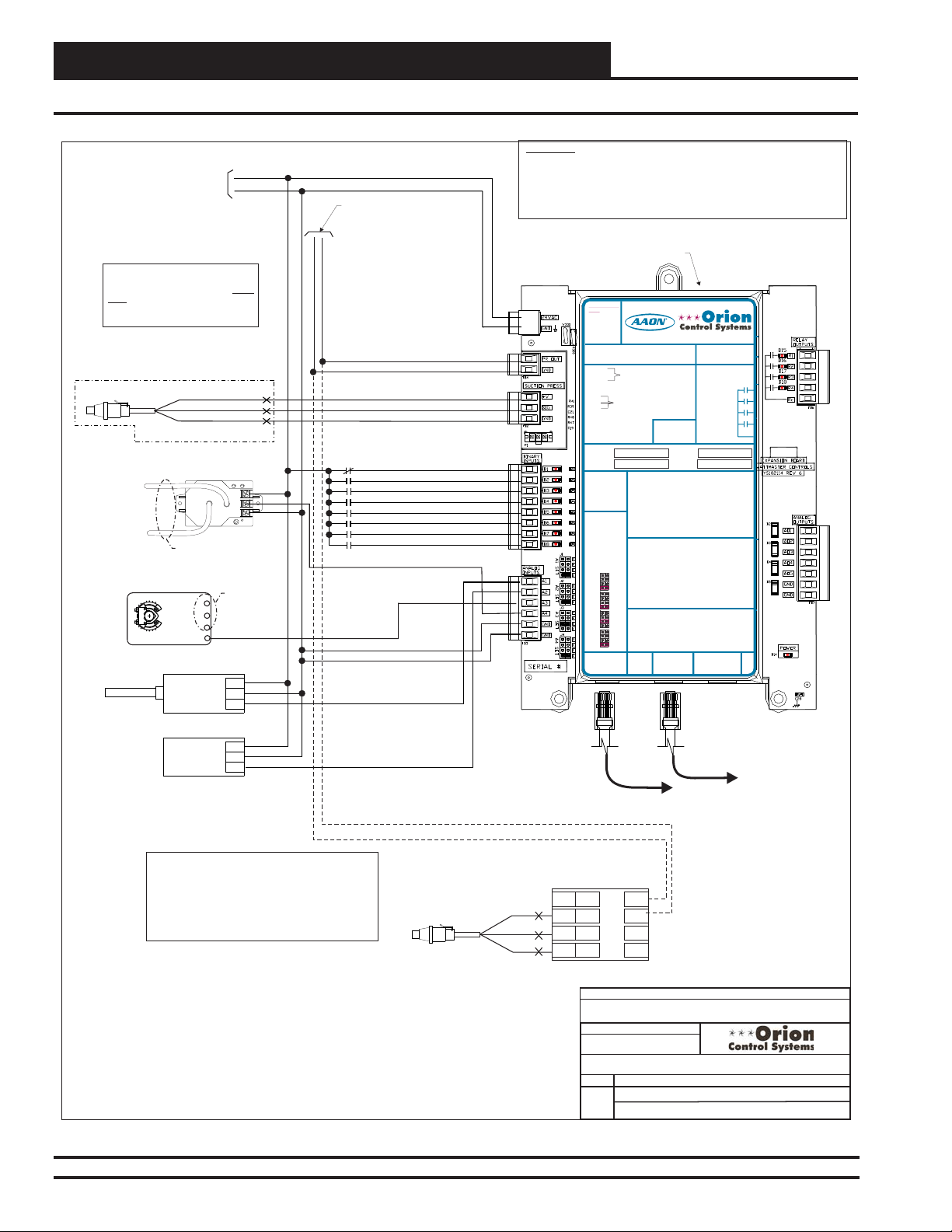
VCM-X Expansion Module Wiring
Y1 3
+ 2
COM - 1
Economizer Feedback 5
Input Wiring
GND
0-5V
GND
LOW
VIN
24 VAC
GND
Is Not
RD
WH
BK
+
+
EXC
+
OUT
COM
-
See Economizer
Actuator Wiring
For VCM-X
AO1
Controller
Connect PR OUT To AI5 &
GND To GND On VCM-X
Controller When Either Suction
Pressure Transducer Is Used
Emergency Shutdown - N.C. Contact
Dirty Filter - N.O. Contact
Proof Of Flow - N.O. Contact
Remote Forced Occupied - N.O. Contact
Remote Forced Heating - N.O. Contact
Remote Forced Cooling - N.O. Contact
Hood On - N.O. Contact
Remote Forced Dehumidification
N.O. Contact
10 VA Minimum Power
Required For
VCM-X Expansion Module
Note:
1.) If Unit Has Dehumidification Option
And Copeland Digital Compressor
Used
, Wire Suction Pressure
Transducer Directly To VCM-X
Expansion Module As Shown.
Suction Pressure Transducer
Building Pressure
Plastic Tubing To Building
Pressure Sensing Locations
Economizer Damper Actuator
(Belimo Actuator Shown)
Outdoor Air
Humidity Sensor
VAC OR DC
Indoor Air
Humidity Sensor
VOUT (0-5V)
Transducer
HIGH
PR OUT
GND
SIG
GND
GND
GND
WARNING!!
Observe Polarity! All boards must be wired with GND-to-GND and 24VAC-to24VAC. Failure to observe polarity will result in damage to one or more of the
boards. Expansion Modules must be wired in such a way that the expansion
modules and the controller are always powered together. Loss of power to the
expansion module will cause the controller to become inoperative until power is
restored to the expansion module.
VCM-X Expansion Module
24 VAC POWER
24 VAC POWER ONLY
ONLY
WARNING!POLARITY MUST BE
WARNING!
OBSERVED OR THE BOARD
POLARITY
WILLBE DAMAGED
MUST BE
OBSERVED OR
THE BOARD
POLARITY
WARNING
OBSERVE
+V
B 1I
B 2I
B 3I
B 4I
B 5I
B 6I
B 7I
BI8
AI1
AI2
AI3
AI4
www.aaon.com
WILLBE
DAMAGED
VCM-X Expansion Module
VCM-X Expansion Module
Orion No.:OE333-23-EM
Orion No.:OE333-23-EM
PR OUT
GND
PR OUT
OE333-23-EM-AVCM-X EXPANSION MODULE
GND
PR OUT
GND
SUCTION PRESSURE
+V
SUCTION PRESSURE
+V
TRANSDUCER CONNECTION
SIG
TRANSDUCER CONNECTION
SIG
FOR HVAC UNITS WITHOUT
GND
FOR HVAC UNITS WITHOUT
GND
DIGITALCOMPRESSOR
DIGITALCOMPRESSOR
SUCTION PRESSURE
+V
TRANSDUCER CONNECTION
SIG
FOR HVAC UNITS WITHOUT
GND
DIGITALCOMPRESSOR
RELAY1 = RELAY3 =
RELAY1 = RELAY3 =
RELAY2 = RELAY4 =
RELAY2 = RELAY4 =
RELAY1 = RELAY3 =
ITIS SUGGESTED
ITIS SUGGESTED
THATYOU WRITE THE
THATYOU WRITE THE
DESCRIPTION OF
DESCRIPTION OF
RELAY2 = RELAY4 =
THE RELAYOUTPUTS
THE RELAYOUTPUTS
YOUARE USING IN
YOUARE USING IN
THE BOXES
THE BOXES
ITIS SUGGESTED
PROVIDEDABOVE
PROVIDEDABOVE
THATYOU WRITE THE
WITHA PERMANENT
WITHA PERMANENT
DESCRIPTION OF
MARKER (SHARPIE®)
MARKER (SHARPIE®)
THE RELAYOUTPUTS
YOUARE USING IN
THE BOXES
PROVIDEDABOVE
ANALOG INPUT
WITHA PERMANENT
ANALOG INPUT
MARKER (SHARPIE®)
JUMPER SETTINGS
JUMPER SETTINGS
MUSTBE SET AS
MUSTBE SET AS
SHOWN FOR
SHOWN FOR
PROPER
PROPER
ANALOG INPUT
OPERATION
OPERATION
JUMPER SETTINGS
MUSTBE SET AS
SHOWN FOR
ANALOG INPUT
ANALOG INPUT
PROPER
JUMPER
JUMPER
OPERATION
SETTINGS
SETTINGS
THERM
THERM
ANALOG INPUT
4-20mA
4-20mA
AI1
AI1
JUMPER
0-10V
0-10V
SETTINGS
0-5V
0-5V
THERM
THERM
THERM
4-20mA
4-20mA
4-20mA
AI2
AI1
AI2
0-10V
0-10V
0-10V
0-5V
0-5V
0-5V
THERM
THERM
THERM
4-20mA
4-20mA
4-20mA
AI2
AI3
AI3
0-10V
0-10V
0-10V
0-5V
0-5V
0-5V
THERM
THERM
THERM
4-20mA
4-20mA
4-20mA
AI3
AI4
0-10V
AI4
0-10V
0-10V
0-5V
0-5V
0-5V
THERM
4-20mA
AI4
0-10V
24 VAC POWER ONLY
I2C
0-5V
WARNING!POLARITY MUST BE
EXPANSION
OBSERVED OR THE BOARD
WILLBE DAMAGED
I2C
WattMaster Label
EXPANSION
#LB102034-01
www.aaon.com
TO VCM-X INPUT
TERMINALS AI5 & GND
TO VCM-X INPUT
TERMINALS AI5 & GND
TO VCM-X INPUT
TERMINALSAI5 & GND
BI1 = EMERGENCY SHUTDOWN - N.C. INPUT
BI1 = EMERGENCY SHUTDOWN - N.C. INPUT
= DIRTY FILTER - N.O. INPUT
BI2
= DIRTY FILTER - N.O. INPUT
BI2
= PROOF OF FLOW - N.O. INPUT
BI3
= PROOF OF FLOW - N.O. INPUT
BI3
= REMOTE FORCED OCCUPIED - N.O. INPUT
BI4
= REMOTE FORCED OCCUPIED - N.O. INPUT
BI4
= REMOTE FORCED HEATING - N.O. INPUT
BI5
BI1 = HOOD ON - N.O. INPUT
= REMOTE FORCED HEATING - N.O. INPUT
BI5
= REMOTE FORCED COOLING - N.O. INPUT
BI6
= DIRTY FILTER - N.O. INPUT
BI2
= REMOTE FORCED COOLING - N.O. INPUT
BI6
= HOOD ON - N.O. INPUT
BI7
= PROOF OF FLOW - N.O. INPUT
BI3
= HOOD ON - N.O. INPUT
BI7
= REMOTE DEHUMIDIFICATION - N.O. INPUT
BI8
= REMOTE FORCED OCCUPIED - N.O. INPUT
BI4
= REMOTE DEHUMIDIFICATION - N.O. INPUT
BI8
= REMOTE FORCED HEATING - N.O. INPUT
BI5
= REMOTE FORCED COOLING - N.O. INPUT
BI6
NOTE:
NOTE:
= SMOKE DETECTOR - N.C. INPUT
BI7
ALL BINARYINPUTS MUST BE 24 VAC ONLY.
ALL BINARYINPUTS MUST BE 24 VAC ONLY.
= REMOTE DEHUMIDIFICATION - N.O. INPUT
BI8
AO1 = BUILDING PRESSURE CONTROL VFD OR
NOTE:
AO1 = BUILDING PRESSURE CONTROL VFD OR
ALL BINARYINPUTS MUST BE 24 VAC ONLY.
AO2
= MODULATING HEATING SIGNAL
AO2
AO1 = BUILDING PRESSURE CONTROL VFD OR
AO3
= MODULATING COOLING/DIGITALSCROLL
AO3
AO2
= MODULATING HEATING SIGNAL
AO4
= RETURN AIR DAMPERACTUATOR
AO4
AO3
= MODULATING COOLING/DIGITALSCROLL
AO5
= RETURN AIR BYPASS DAMPERACTUATOR
AO5
AO4
= RETURNAIR DAMPER ACTUATOR
GND
= GROUND FOR ANALOG OUTPUTS
GND
= GROUND FOR ANALOG OUTPUTS
GND
GND
AO5
= RETURNAIR BYPASS DAMPER ACTUATOR
GND
= GROUND FORANALOG OUTPUTS
AI1 = OUTDOOR AIR RH SENSOR (0-5 VDC)
AI1 = OUTDOOR AIR RH SENSOR (0-5 VDC)
GND
= GROUND FORANALOG OUTPUTS
AI2
= INDOOR AIR RH SENSOR (0-5 VDC)
AI2
= INDOOR AIR RH SENSOR (0-5 VDC)
A3
= ECONOMIZER FEEDBACK
I
A3
= ECONOMIZER FEEDBACK
I
AI4
= BUILDING STATIC PRESSURE (0-5 VDC)
AI4
= BUILDING STATIC PRESSURE (0-5 VDC)
AI1 = OUTDOOR AIR RH SENSOR (0-5 VDC)
GND
GND
= INDOORAIR RH SENSOR (0-5 VDC)
AI2
GND
GND
= CO2 (0-10 VDC)
AI3
= BUILDING STATIC PRESSURE (0-5 VDC)
AI4
= GROUND FORANALOG INPUTS
GND
= GROUND FORANALOG INPUTS
GND
www.orioncontrols.com
www.orioncontrols.com
AAON No.:
AAON No.:
www.orioncontrols.com
RELAYCONTACT
RATING IS 1AMP
RELAYCONTACT
MAX @ 24 VAC
RATING IS 1AMP
MAX @ 24 VAC
RELAYCONTACT
RATING IS 1AMP
MAX @ 24 VAC
RELAY
COMMON
DAMPER ACTUATOR (0-10 OR 2-10 VDC)
DAMPER ACTUATOR (0-10 OR 2-10 VDC)
= MODULATING HEATING SIGNAL
(0-10 VDC OR 2-10 VDC)
(0-10 VDC OR 2-10 VDC)
= MODULATING COOLING/DIGITALSCROLL
DAMPERACTUATOR (0-10 OR 2-10 VDC)
SIGNAL (0-10 VDC, 2-10 VDC OR 1.5-5 VDC)
SIGNAL (0-10 VDC, 2-10 VDC OR 1.5-5 VDC)
= RETURN AIR DAMPERACTUATOR
(0-10 VDC OR 2-10 VDC)
(0-10 VDC)
(0-10 VDC)
= RETURN AIR BYPASS DAMPERACTUATOR
SIGNAL (0-10 VDC, 2-10 VDC OR 1.5-5 VDC)
(0-10 VDC)
(0-10 VDC)
= GROUND FOR ANALOG OUTPUTS
(0-10 VDC)
= GROUND FOR ANALOG OUTPUTS
(0-10 VDC)
= GROUND FOR ANALOG INPUTS
= GROUND FOR ANALOG INPUTS
= GROUND FOR ANALOG INPUTS
= GROUND FOR ANALOG INPUTS
I2C
I2C
EXPANSION
EXPANSION
WattMaster Label
WattMasterLabel
#LB102034-01-A
#LB102034-01-A
Rev.: 1K
Rev.: 1L
Connect To VCM-X E-BUS
I2C
EXPANSION
R69190
R69190
RELAY1
RELAY1
RELAY2
RELAY2
RELAY1
RELAY3
RELAY3
RELAY2
RELAY4
RELAY4
RELAY
RELAY3
COMMON
RELAY
COMMON
RELAY4
I2C
EXPANSION
Modular Cable
Controller
VCM
Note:
1.) If Unit Has Dehumidification Option And Copeland Digital
Compressor Is Used, Wire Suction Pressure Transducer To
Copeland Controller As Shown.
2.) The Modulating Cooling Output Voltage Must Be
Configured For 1.5 - 5 VDC Operation When YouAre
Setting Up The VCM-X Controller
Operating Parameters.
Suction Pressure
Transducer
Figure 23: OE333-23-EM - VCM-X Expansion Module Input Wiring
42
VCM-X Component & Systems Wiring
RD
WH
BK
Copeland Digital
Compressor Controller
SHLD
P4
EXC
P3
OUT
P2
P1
COM
REVISED:
FILENAME
OVCMX-Exp-Inputs-1A.CDR
PAGE
1 of 1
Modular Cable
Connect To Next Expansion Board
(When Used)
P5
P6
C1
C2
JOB NAME
S. Olson
DATE:
05/12/15
01/11/13
DESCRIPTION:
VCM-X Expansion Module
Input Wiring
S. Olson
Page 43

24 VAC
GND
VCM-X Expansion
Module
10 VA Minimum
Power Required For
VCM-X Expansion
Module
POLARITY
WARNING
OBSERVE
Note:
All Relay Outputs Are Normally
Open And Rated For 24 VAC
Power Only. 1Amp Maximum
Load.
24 VAC POWER
24 VAC POWER ONLY
ONLY
WARNING!POLARITY MUST BE
WARNING!
OBSERVED OR THE BOARD
POLARITY
WILLBE DAMAGED
MUST BE
OBSERVED OR
THE BOARD
WILL BE
DAMAGED
VCM-X Expansion Module
Orion No.:OE333-23-EM
PR OUT
OE333-23-EM-AVCM-X EXPANSION MODULE
GND
PR OUT
GND
+V
SIG
GND
+V
SIG
GND
RELAY1 = RELAY3 =
RELAY2 = RELAY4 =
RELAY1 = RELAY3 =
ITIS SUGGESTED
THATYOU WRITE THE
DESCRIPTION OF
RELAY2 = RELAY4 =
THE RELAYOUTPUTS
YOUARE USING IN
THE BOXES
ITIS SUGGESTED
PROVIDEDABOVE
THATYOU WRITE THE
WITHA PERMANENT
DESCRIPTION OF
MARKER (SHARPIE®)
THE RELAYOUTPUTS
YOUARE USING IN
THE BOXES
PROVIDEDABOVE
WITHA PERMANENT
ANALOG INPUT
MARKER (SHARPIE®)
JUMPER SETTINGS
MUST BE SETAS
SHOWN FOR
PROPER
ANALOG INPUT
OPERATION
JUMPER SETTINGS
MUSTBE SET AS
SHOWN FOR
ANALOG INPUT
PROPER
JUMPER
OPERATION
SETTINGS
THERM
ANALOG INPUT
4-20mA
AI1
JUMPER
0-10V
SETTINGS
0-5V
THERM
THERM
4-20mA
4-20mA
AI1
AI2
0-10V
0-10V
0-5V
0-5V
THERM
THERM
4-20mA
4-20mA
AI2
AI3
0-10V
0-10V
0-5V
0-5V
THERM
THERM
4-20mA
4-20mA
AI3
AI4
0-10V
0-10V
0-5V
0-5V
THERM
4-20mA
AI4
0-10V
I2C
0-5V
EXPANSION
Suction Pressure
Transducer
I2C
WattMaster Label
EXPANSION
#LB102034-01
www.aaon.com
TO VCM-X INPUT
TERMINALS AI5 & GND
TO VCM-X INPUT
TERMINALSAI5 & GND
SUCTION PRESSURE
TRANSDUCER CONNECTION
FOR HVAC UNITS WITHOUT
DIGITALCOMPRESSOR
SUCTION PRESSURE
TRANSDUCER CONNECTION
FOR HVAC UNITS WITHOUT
DIGITALCOMPRESSOR
BI1 = EMERGENCY SHUTDOWN - N.C. INPUT
BI2
= DIRTY FILTER - N.O. INPUT
BI3
= PROOF OF FLOW - N.O. INPUT
BI4
= REMOTE FORCED OCCUPIED - N.O. INPUT
BI1 = HOOD ON - N.O. INPUT
BI5
= REMOTE FORCED HEATING - N.O. INPUT
= DIRTY FILTER - N.O. INPUT
BI2
BI6
= REMOTE FORCED COOLING - N.O. INPUT
= PROOF OF FLOW - N.O. INPUT
BI3
BI7
= HOOD ON - N.O. INPUT
= REMOTE FORCED OCCUPIED - N.O. INPUT
BI4
BI8
= REMOTE DEHUMIDIFICATION - N.O. INPUT
= REMOTE FORCED HEATING - N.O. INPUT
BI5
= REMOTE FORCED COOLING - N.O. INPUT
BI6
NOTE:
BI7
= SMOKE DETECTOR - N.C. INPUT
ALL BINARYINPUTS MUST BE 24 VAC ONLY.
BI8
= REMOTE DEHUMIDIFICATION - N.O. INPUT
NOTE:
AO1 = BUILDING PRESSURE CONTROL VFD OR
ALL BINARYINPUTS MUST BE 24 VAC ONLY.
DAMPER ACTUATOR (0-10 OR 2-10 VDC)
= MODULATING HEATING SIGNAL
AO2
(0-10 VDC OR 2-10 VDC)
AO1 = BUILDING PRESSURE CONTROL VFD OR
= MODULATING COOLING/DIGITALSCROLL
AO3
DAMPER ACTUATOR (0-10 OR 2-10 VDC)
SIGNAL (0-10 VDC, 2-10 VDC OR 1.5-5 VDC)
= MODULATING HEATING SIGNAL
AO2
= RETURN AIR DAMPERACTUATOR
AO4
(0-10 VDC OR 2-10 VDC)
(0-10 VDC)
= MODULATING COOLING/DIGITALSCROLL
AO3
= RETURN AIR BYPASS DAMPERACTUATOR
AO5
SIGNAL (0-10 VDC, 2-10 VDC OR 1.5-5 VDC)
(0-10 VDC)
AO4
= RETURN AIR DAMPERACTUATOR
= GROUND FOR ANALOG OUTPUTS
GND
(0-10 VDC)
= GROUND FOR ANALOG OUTPUTS
GND
AO5
= RETURN AIR BYPASS DAMPERACTUATOR
(0-10 VDC)
GND
= GROUND FORANALOG OUTPUTS
AI1 = OUTDOOR AIR RH SENSOR (0-5 VDC)
GND
= GROUND FORANALOG OUTPUTS
AI2
= INDOOR AIR RH SENSOR (0-5 VDC)
A3
= ECONOMIZER FEEDBACK
I
AI4
= BUILDING STATIC PRESSURE (0-5 VDC)
AI1 = OUTDOOR AIR RH SENSOR (0-5 VDC)
GND
= GROUND FOR ANALOG INPUTS
AI2
= INDOORAIR RH SENSOR (0-5 VDC)
GND
= GROUND FOR ANALOG INPUTS
AI3
= CO2 (0-10 VDC)
AI4
= BUILDING STATIC PRESSURE (0-5 VDC)
GND
= GROUND FORANALOG INPUTS
GND
= GROUND FORANALOG INPUTS
www.orioncontrols.com
www.orioncontrols.com
I2C
EXPANSION
Modular Cable
Connect To VCM-X
E-BUS Controller
Modular Cable
Connect To Next Expansion
Board (When Used)
RD
WH
BK
I2C
EXPANSION
AAON No.:
R69190
RELAYCONTACT
RATING IS 1AMP
MAX @ 24 VAC
RELAYCONTACT
RATING IS 1AMP
RELAY1
MAX @ 24 VAC
RELAY2
RELAY1
RELAY3
RELAY2
RELAY4
RELAY3
RELAY
RELAY4
COMMON
RELAY
COMMON
WattMaster Label
#LB102034-01-A
Rev.: 1L
Copeland Digital
Compressor Controller
P4
P3
P2
P1
Copeland Digital Compressor Wiring Detail
VCM-X Expansion Module Wiring
Output Wiring
WARNING!!
Observe Polarity! All boards must be wired with GND-to-GND and
24VAC-to-24VAC. Failure to observe polarity will result in damage to
one or more of the boards. Expansion Modules must be wired in
such a way that the expansion modules and the controller are
always powered together. Loss of power to the expansion module
will cause the controller to become inoperative until power is
restored to the expansion module.
Either A Building Pressure
Damper Actuator Or a
Building Pressure Relief
Fan VFD Can Be Used,
Building Pressure Control
Damper Actuator
1 COM
2 +
-
3Y1
Building Pressure
Relief Fan VFD
+
COM
Modulating Heating
(0 to 10 VDC Input)
+
COM
Modulating Cooling
Or Digital Scroll Compressor
(1.5 To 5, 0To 10 Or 2 To 10 VDC Input)
+
COM
Return Air
Damper Actuator
(0-10 VDC)
1 COM
2 +
3Y1
Return Air Bypass
Damper Actuator
(0-10 VDC)
1 COM
2 +
3Y1
JOB NAME
05/14/15
REVISED:
FILENAME
VCMX-Exp-Outputs-1B.CDR
01/11/13
DATE:
PAGE
1 of 1
DESCRIPTION:
VCM-X Expansion Module
Output Wiring
Note:
1.) The Modulating
Cooling Device Used
Must Be Capable Of
Accepting Either A 0-10
VDC, 2-10 VDC or 1.5-
5.0 VDC Input. The
Modulating Cooling
Output Voltage Is User
Configurable For These
Voltages. The
Modulating Heating
Devices Used Must Be
Capable of Accepting
Either A 0-10 VDC or 210 VDC Input. The
Modulating Heating
Output Voltage Is UserConfigurable For These
Voltages. These Voltage
Outputs Must Also Be
Configured When You
Are Setting Up The
VCM-X Controller(s)
Operating Parameters.
2.) Each Modulating
Heating Or Cooling
Device Used On The
VCM-X Controller Must
Have (1) Relay Output
Configured For Each
Device Used, In Order
To Enable The
Modulating Heating
And/Or Cooling Device's
Sequence. This Relay
Output Must Be
Configured When
Setting Up The VCM-X
Controller Operating
Parameters.
S. Olson
S. Olson
SHLD
EXC
OUT
COM
Relay Output Contacts R1 Through R4 May
Be User-Configured For The Following:
1 - Heating Stages
2 - Cooling Stages
3 - Warm-up Mode Command (VAV Boxes)
4 - Reversing Valve (Heat Pumps)
5 - Reheat Control (Dehumidification)
6 - Exhaust Fan Interlock
7 - Preheater For Low Ambient Protection
8 - Alarm
9 - Override
10 - Occupied
11 - OADamper
12 - Heat Wheel
13 - Emergency Heat
Note:
A Total Of 20 Relays Are Available By
Adding Relay Expansion Modules. All
Expansion Module Relay Outputs Are User
Configurable As Listed Above.
R1
Configurable Relay Output #1
R2
Configurable Relay Output #2
R3
Configurable Relay Output #3
R4
Configurable Relay Output #4
VCM
A1O
AO2
AO3
AO4
AO5
GND
GND
P5
P6
C1
C2
When Copeland
Digital Compressor
Is Used, Wire Per
Copeland Digital
Compressor Wiring
Detail
Belimo Actuator Wiring
Shown. Consult Factory
For Other Manufacturer
Wiring Instructions
Note:
1.) If Unit Has Dehumidification Option And Copeland Digital
Compressor Is Used, Wire Suction Pressure Transducer To Copeland
Controller As Shown.
2.) The Modulating Cooling Output Voltage Must Be Configured For 1.5
- 5 VDC Operation When YouAre Setting Up The VCM-X Controller
Operating Parameters For The Copeland Digital Compressor.
Figure 24: OE333-23-EM - VCM-X Expansion Module Output Wiring
VCM-X Component & Systems Wiring
43
Page 44

VCM-X Expansion Module Wiring
Suction Pressure Transducer Without Digital Compressor
WARNING!!
10 VA Minimum Power Required
For VCM-X Expansion Module
24 VAC
GND
Note:
1.) If Unit Has Dehumidification
Option And Copeland Digital
Compressor , Wire
Suction Pressure Transducer
To VCM-X Expansion Module As Shown.
Is Not Used
Directly
OE275-01
Suction Pressure
RD
WH
BK
Caution:
1.) The Schraeder Port Used For Installation
Of The Suction Pressure Transducer Should
Be Located In A Vertical Portion Of The
Suction Line To Prevent Refrigerant Oil
From Accumulating In The Sensor.
Note:
1.) If Unit Has Dehumidification Option
And Copeland Digital Compressor Is Used,
Wire Suction Pressure Transducer To
Copeland Controller As Shown On
Following Page.
2.) AO3 Output Voltage Must Be
Configured For 1.5 - 5 VDC Operation
When You Are Setting Up The VCM-X
Controller Operating Parameters For A
Copeland Digital Compressor.
Connect PR
OUT To AI5 &
GND To GND
On VCM-X
Controller
When The
Suction
Pressure
Transducer Is
Used
PR OUT
Observe Polarity! All boards must be wired with GND-to-GND and
24VAC-to-24VAC. Failure to observe polarity will result in damage
to one or more of the boards. Expansion Modules must be wired in
such a way that the expansion modules and the controller are
always powered together. Loss of power to the expansion module
will cause the controller to become inoperative until power is
restored to the expansion module.
24 VAC POWER
GND
+V
SIG
GND
24 VAC POWER ONLY
ONLY
WARNING!POLARITY MUST BE
WARNING!
OBSERVED OR THE BOARD
POLARITY
WILL BE DAMAGED
MUST BE
OBSERVED OR
POLARITY
WARNING
OBSERVE
THE BOARD
WILL BE
DAMAGED
VCM-X Expansion Module
Orion No.:OE333-23-EM
PR OUT
TO VCM-X INPUT
OE333-23-EM-AVCM-X EXPANSION MODULE
GND
TERMINALS AI5 & GND
PR OUT
TO VCM-X INPUT
GND
TERMINALS AI5 & GND
SUCTION PRESSURE
+V
TRANSDUCER CONNECTION
SIG
FOR HVAC UNITS WITHOUT
GND
DIGITALCOMPRESSOR
SUCTION PRESSURE
+V
TRANSDUCER CONNECTION
SIG
FOR HVAC UNITS WITHOUT
GND
DIGITALCOMPRESSOR
RELAY1 = RELAY3 =
RELAY2 = RELAY4 =
ITIS SUGGESTED
RELAY1 = RELAY3 =
THATYOU WRITE THE
DESCRIPTION OF
RELAY2 = RELAY4 =
THE RELAYOUTPUTS
YOUARE USING IN
THE BOXES
ITIS SUGGESTED
PROVIDEDABOVE
THATYOU WRITE THE
WITHA PERMANENT
DESCRIPTION OF
MARKER (SHARPIE®)
THE RELAYOUTPUTS
YOUARE USING IN
THE BOXES
PROVIDEDABOVE
ANALOG INPUT
WITHA PERMANENT
JUMPER SETTINGS
MARKER (SHARPIE®)
MUST BE SETAS
SHOWN FOR
PROPER
ANALOG INPUT
OPERATION
JUMPER SETTINGS
MUST BE SETAS
SHOWN FOR
ANALOG INPUT
PROPER
JUMPER
OPERATION
SETTINGS
THERM
4-20mA
ANALOG INPUT
AI1
0-10V
JUMPER
0-5V
SETTINGS
THERM
THERM
4-20mA
AI2
4-20mA
AI1
0-10V
0-10V
0-5V
0-5V
THERM
THERM
4-20mA
4-20mA
AI3
AI2
0-10V
0-10V
0-5V
0-5V
THERM
THERM
4-20mA
4-20mA
AI4
AI3
0-10V
0-10V
0-5V
0-5V
THERM
4-20mA
AI4
0-10V
I2C
0-5V
EXPANSION
I2C
WattMaster Label
EXPANSION
www.aaon.com
www.orioncontrols.com
BI1 = EMERGENCY SHUTDOWN - N.C. INPUT
BI2
= DIRTY FILTER - N.O. INPUT
BI3
= PROOF OF FLOW - N.O. INPUT
BI4
= REMOTE FORCED OCCUPIED - N.O. INPUT
BI5
= REMOTE FORCED HEATING - N.O. INPUT
BI1 = HOOD ON - N.O. INPUT
BI6
= REMOTE FORCED COOLING - N.O. INPUT
= DIRTY FILTER - N.O. INPUT
BI2
BI7
= HOOD ON - N.O. INPUT
= PROOF OF FLOW - N.O. INPUT
BI3
BI8
= REMOTE DEHUMIDIFICATION - N.O. INPUT
= REMOTE FORCED OCCUPIED - N.O. INPUT
BI4
= REMOTE FORCED HEATING - N.O. INPUT
BI5
NOTE:
= REMOTE FORCED COOLING - N.O. INPUT
BI6
ALL BINARY INPUTS MUSTBE 24 VAC ONLY.
= SMOKE DETECTOR - N.C. INPUT
BI7
= REMOTE DEHUMIDIFICATION - N.O. INPUT
BI8
AO1 = BUILDING PRESSURE CONTROL VFD OR
NOTE:
DAMPER ACTUATOR (0-10 OR 2-10 VDC)
ALL BINARYINPUTS MUST BE 24 VAC ONLY.
= MODULATING HEATING SIGNAL
AO2
(0-10 VDC OR 2-10 VDC)
= MODULATING COOLING/DIGITALSCROLL
AO3
AO1 = BUILDING PRESSURE CONTROL VFD OR
SIGNAL (0-10 VDC, 2-10 VDC OR 1.5-5 VDC)
DAMPER ACTUATOR (0-10 OR 2-10 VDC)
= RETURN AIR DAMPERACTUATOR
AO4
= MODULATING HEATING SIGNAL
AO2
(0-10 VDC)
(0-10 VDC OR 2-10 VDC)
AO5
= RETURN AIR BYPASS DAMPERACTUATOR
= MODULATING COOLING/DIGITALSCROLL
AO3
(0-10 VDC)
SIGNAL (0-10 VDC, 2-10 VDC OR 1.5-5 VDC)
GND
= GROUND FOR ANALOG OUTPUTS
AO4
= RETURN AIR DAMPERACTUATOR
GND
= GROUND FOR ANALOG OUTPUTS
(0-10 VDC)
AO5
= RETURN AIR BYPASS DAMPERACTUATOR
(0-10 VDC)
AI1 = OUTDOOR AIR RH SENSOR (0-5 VDC)
GND
= GROUND FOR ANALOG OUTPUTS
AI2
= INDOOR AIR RH SENSOR (0-5 VDC)
GND
= GROUND FOR ANALOG OUTPUTS
A3
= ECONOMIZER FEEDBACK
I
AI4
= BUILDING STATIC PRESSURE (0-5 VDC)
AI1 = OUTDOOR AIR RH SENSOR (0-5 VDC)
GND
= GROUND FOR ANALOG INPUTS
= INDOOR AIR RH SENSOR (0-5 VDC)
AI2
GND
= GROUND FOR ANALOG INPUTS
= CO2 (0-10 VDC)
AI3
= BUILDING STATIC PRESSURE (0-5 VDC)
AI4
GND
= GROUND FOR ANALOG INPUTS
I2C
= GROUND FOR ANALOG INPUTS
GND
EXPANSION
#LB102034-01
www.orioncontrols.com
AAON No.:
RELAYCONTACT
RATING IS 1AMP
MAX @ 24 VAC
RELAYCONTACT
RATING IS 1AMP
MAX @ 24 VAC
RELAY
COMMON
WattMaster Label
#LB102034-01-A
EXPANSION
R69190
RELAY1
RELAY2
RELAY1
RELAY3
RELAY2
RELAY4
RELAY3
RELAY
COMMON
RELAY4
Rev.: 1L
I2C
VCM
VCM-X Expansion
Module
Connect To VCM-X E-BUS
REVISED:
FILENAME
O-VCM-X-SuctP-WO-DigC-1B.CDR
DATE:
PAGE
1 of 1
01/10/13
VCM-X E-BUS Expansion Module
Suction Pressure Transducer w/o Digital Comp.
Figure 25: OE275-01 Suction Pressure Transducer Without Digital Compressor Wiring
44
VCM-X Component & Systems Wiring
Modular Cable
Controller
Modular Cable
Connect To Next Expansion
Board(When Used)
JOB NAME
05/14/15
S. Olson
S. Olson
DESCRIPTION:
Page 45
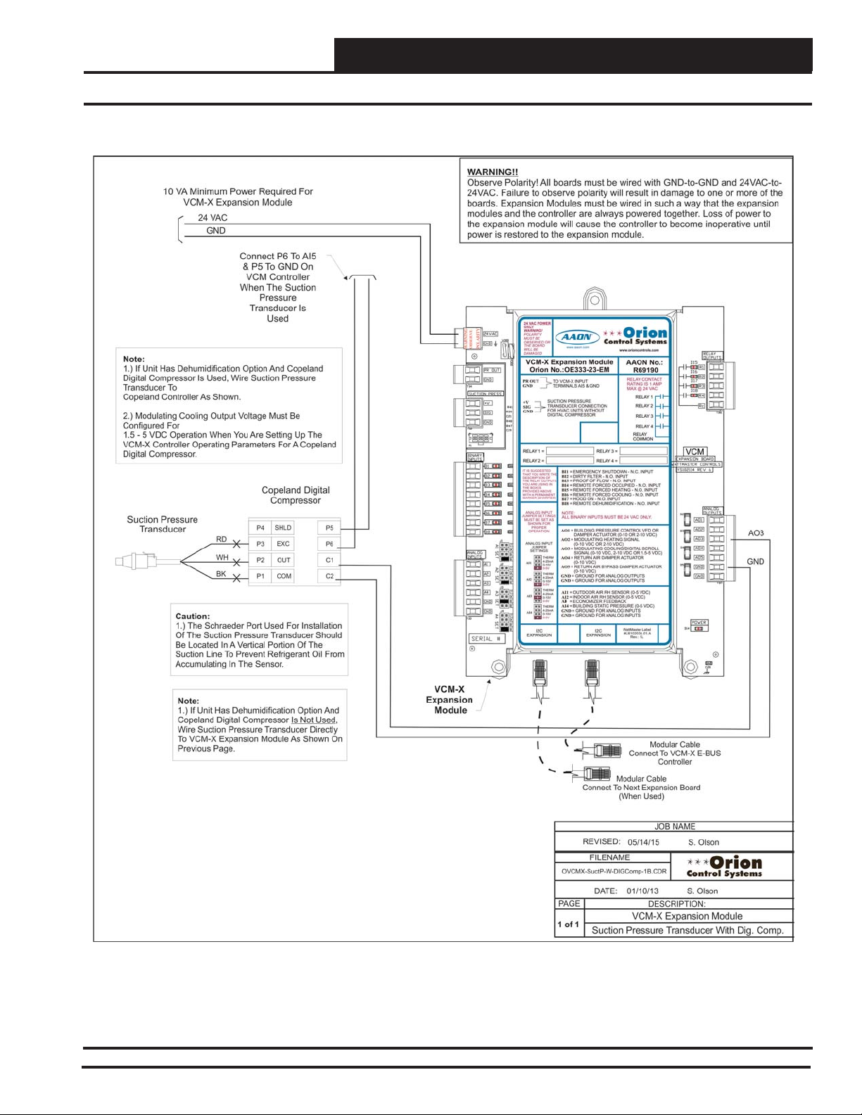
VCM-X Expansion Module Wiring
Suction Pressure Transducer With Digital Compressor
Figure 26: OE275-01 Suction Pressure Transducer With Digital Compressor Wiring
VCM-X Component & Systems Wiring
45
Page 46
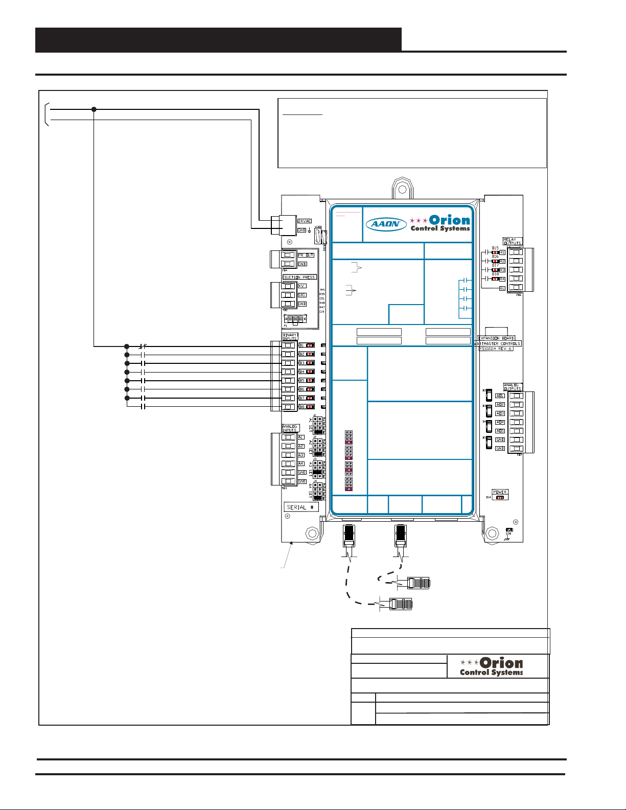
VCM-X Expansion Module Wiring
Expansion Module Binary Inputs
24 VAC
GND
10 VA Minimum Power Required For
VCM-X Expansion Module
Emergency Shutdown - N.C. Contact
Dirty Filter - N.O. Contact
Proof Of Flow - N.O. Contact
Remote Forced Occupied - N.O. Contact
Remote Forced Heating - N.O. Contact
Remote Forced Cooling - N.O. Contact
Hood On - N.O. Contact
Remote Forced Dehumidification
N.O. Contact
WARNING!!
Observe Polarity! All boards must be wired with GND-to-GND and 24VAC-to24VAC. Failure to observe polarity will result in damage to one or more of the
boards. Expansion Modules must be wired in such a way that the expansion
modules and the controller are always powered together. Loss of power to the
expansion module will cause the controller to become inoperative until power is
restored to the expansion module.
24 VAC POWER
BI1
BI2
BI3
BI4
BI5
BI6
BI7
BI8
24 VAC POWER ONLY
ONLY
WARNING!POLARITY MUST BE
WARNING!
OBSERVED OR THE BOARD
POLARITY
WILL BE DAMAGED
MUST BE
OBSERVED OR
POLARITY
WARNING
OBSERVE
THE BOARD
WILL BE
DAMAGED
VCM-X Expansion Module
Orion No.:OE333-23-EM
PR OUT
TO VCM-X INPUT
OE333-23-EM-A VCM-X EXPANSION MODULE
GND
TERMINALS AI5 & GND
PR OUT
TO VCM-X INPUT
GND
TERMINALS AI5 & GND
SUCTION PRESSURE
+V
TRANSDUCER CONNECTION
SIG
FOR HVAC UNITS WITHOUT
GND
DIGITALCOMPRESSOR
SUCTION PRESSURE
+V
TRANSDUCER CONNECTION
SIG
FOR HVAC UNITS WITHOUT
GND
DIGITALCOMPRESSOR
RELAY 1 = RELAY 3 =
RELAY 2 = RELAY 4 =
IT IS SUGGESTED
RELAY 1 = RELAY 3 =
THATYOU WRITE THE
DESCRIPTION OF
RELAY 2 = RELAY 4 =
THE RELAYOUTPUTS
YOUARE USING IN
THE BOXES
IT IS SUGGESTED
PROVIDEDABOVE
THATYOU WRITE THE
WITHA PERMANENT
DESCRIPTION OF
MARKER (SHARPIE®)
THE RELAYOUTPUTS
YOUARE USING IN
THE BOXES
PROVIDEDABOVE
ANALOG INPUT
WITHA PERMANENT
JUMPER SETTINGS
MARKER (SHARPIE®)
MUST BE SETAS
SHOWN FOR
PROPER
ANALOG INPUT
OPERATION
JUMPER SETTINGS
MUST BE SETAS
SHOWN FOR
ANALOG INPUT
PROPER
JUMPER
OPERATION
SETTINGS
THERM
ANALOG INPUT
4-20mA
AI1
JUMPER
0-10V
SETTINGS
0-5V
THERM
THERM
4-20mA
4-20mA
AI2
AI1
0-10V
0-10V
0-5V
0-5V
THERM
THERM
4-20mA
4-20mA
AI2
AI3
0-10V
0-10V
0-5V
0-5V
THERM
THERM
4-20mA
4-20mA
AI3
AI4
0-10V
0-10V
0-5V
0-5V
THERM
4-20mA
AI4
0-10V
I2C
0-5V
EXPANSION
I2C
WattMaster Label
EXPANSION
#LB102034-01
www.aaon.com
www.orioncontrols.com
BI1 = EMERGENCY SHUTDOWN - N.C. INPUT
BI2
= DIRTY FILTER - N.O. INPUT
BI3
= PROOF OF FLOW - N.O. INPUT
BI4
= REMOTE FORCED OCCUPIED - N.O. INPUT
BI5
= REMOTE FORCED HEATING - N.O. INPUT
BI1 = HOOD ON - N.O. INPUT
BI6
= REMOTE FORCED COOLING - N.O. INPUT
= DIRTY FILTER - N.O. INPUT
BI2
BI7
= HOOD ON - N.O. INPUT
= PROOF OF FLOW - N.O. INPUT
BI3
BI8
= REMOTE DEHUMIDIFICATION - N.O. INPUT
= REMOTE FORCED OCCUPIED - N.O. INPUT
BI4
= REMOTE FORCED HEATING - N.O. INPUT
BI5
= REMOTE FORCED COOLING - N.O. INPUT
BI6
NOTE:
= SMOKE DETECTOR - N.C. INPUT
BI7
ALL BINARY INPUTS MUST BE 24 VAC ONLY.
= REMOTE DEHUMIDIFICATION - N.O. INPUT
BI8
AO1 = BUILDING PRESSURE CONTROL VFD OR
NOTE:
DAMPER ACTUATOR (0-10 OR 2-10 VDC)
ALL BINARY INPUTS MUST BE 24 VAC ONLY.
= MODULATING HEATING SIGNAL
AO2
(0-10 VDC OR 2-10 VDC)
AO1 = BUILDING PRESSURE CONTROL VFD OR
= MODULATING COOLING/DIGITALSCROLL
AO3
DAMPER ACTUATOR (0-10 OR 2-10 VDC)
SIGNAL (0-10 VDC, 2-10 VDC OR 1.5-5 VDC)
AO2
= MODULATING HEATING SIGNAL
= RETURN AIR DAMPERACTUATOR
AO4
(0-10 VDC OR 2-10 VDC)
(0-10 VDC)
AO3
= MODULATING COOLING/DIGITALSCROLL
= RETURN AIR BYPASS DAMPERACTUATOR
AO5
SIGNAL (0-10 VDC, 2-10 VDC OR 1.5-5 VDC)
(0-10 VDC)
AO4
= RETURN AIR DAMPERACTUATOR
= GROUND FOR ANALOG OUTPUTS
GND
(0-10 VDC)
= GROUND FOR ANALOG OUTPUTS
GND
AO5
= RETURN AIR BYPASS DAMPERACTUATOR
(0-10 VDC)
AI1 = OUTDOOR AIR RH SENSOR (0-5 VDC)
GND
= GROUND FOR ANALOG OUTPUTS
GND
= GROUND FOR ANALOG OUTPUTS
= INDOOR AIR RH SENSOR (0-5 VDC)
AI2
I
= ECONOMIZER FEEDBACK
A3
= BUILDING STATIC PRESSURE (0-5 VDC)
AI4
AI1 = OUTDOOR AIR RH SENSOR (0-5 VDC)
= GROUND FOR ANALOG INPUTS
GND
= INDOOR AIR RH SENSOR (0-5 VDC)
AI2
= GROUND FOR ANALOG INPUTS
GND
= CO2 (0-10 VDC)
AI3
= BUILDING STATIC PRESSURE (0-5 VDC)
AI4
= GROUND FOR ANALOG INPUTS
GND
GND
I2C
= GROUND FOR ANALOG INPUTS
EXPANSION
I2C
EXPANSION
www.orioncontrols.com
AAON No.:
R69190
RELAY CONTACT
RATING IS 1AMP
MAX @ 24 VAC
RELAY CONTACT
RELAY 1
RATING IS 1AMP
MAX @ 24 VAC
RELAY 2
RELAY 1
RELAY 3
RELAY 2
RELAY 4
RELAY 3
RELAY
COMMON
RELAY 4
RELAY
COMMON
WattMaster Label
#LB102034-01-A
Rev.: 1L
VCM
VCM-X Expansion Module
Figure 27: VCM-X Expansion Module Binary Inputs Wiring
46
Modular Cable
Connect To VCM-X E-BUS
Controller
Modular Cable
Connect To Next Expansion
Board (When Used)
JOB NAME
FILENAME
OVCMX-Exp-BinaryInputs1B.CDR
DATE:
PAGE
1 of 1
05/14/15
VCM-X Expansion Module
S. Olson
DESCRIPTION:
Binary Inputs
VCM-X Component & Systems Wiring
Page 47
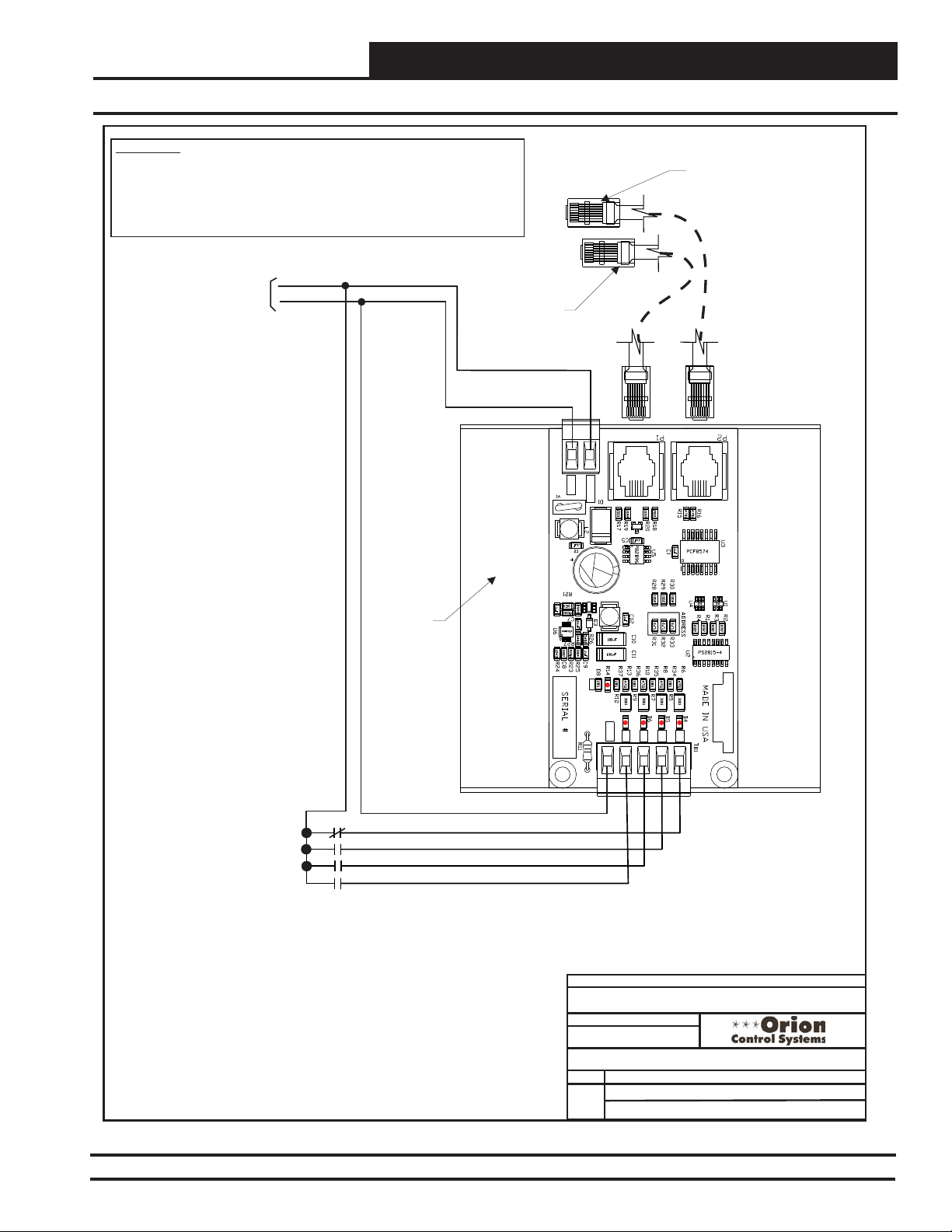
VCM-X Expansion Module Wiring
WARNING!!
Observe Polarity! All boards must be wired with GND-to-GND and 24VAC-to24VAC. Failure to observe polarity will result in damage to one or more of the
boards. Expansion Modules must be wired in such a way that the expansion
modules and the controller are always powered together. Loss of power to
the expansion module will cause the controller to become inoperative until
power is restored to the expansion module.
4 Binary Input Expansion Module
Modular Cable
Connect To VCM-X
E-BUS Controller
5 VA Minimum Power Required
For 4 Binary Input Expansion
Module
24 VAC
GND
OE356-00-BI
4 Binary
Input
Expansion
Module
Modular Cable
Connect To Next
Expansion Board
(When Used)
24 VAC
GND
GND
24VAC
PWR
COM
BI4
BI1
BI3
BI2
VCM BIN EXP BOARD
YS102364 REV1
Emergency Shutdown - N.C. Contact
Dirty Filter - N.O. Contact
Proof Of Flow - N.O. Contact
Remote Forced Occupied - N.O. Contact
Figure 28: OE356-00-BI 4 Binary Input Expansion Module Wiring
VCM-X Component & Systems Wiring
COM
FILENAME
OVCMX-BinInput-4BIN-1A.CDR
PAGE
1 of 1
BI2
BI4
BI3
DATE:
Binary Inputs On 4 Binary Input Module
BI1
JOB NAME
01/10/13
VCM-X Expansion Module
S. Olson
DESCRIPTION:
47
Page 48

VCM-X Expansion Module Wiring
Outdoor Air Humidity Sensor
24 VAC
GND
10 VA Minimum Power Required For
VCM-X Expansion Module
OA Humidity Sensor
Span
VAC or DC
GND
44556
3
2
1
ON
Zero
0-5V or 0-10V
Jumper
6
3
2
1
Must
Be Set To
0-5V As
ON
Shown
4
3
2
1
ON
Jumpers Must Be
Set as Shown
For Correct
O-5 VDC
Operation
1 & 3 Are Off
2 & 4 Are On
4-20 mA
4ON321
Zone
Zone
WARNING!!
Observe Polarity! All boards must be wired with GND-to-GND and 24VAC-to24VAC. Failure to observe polarity will result in damage to one or more of the
boards. Expansion Modules must be wired in such a way that the expansion
modules and the controller are always powered together. Loss of power to
the expansion module will cause the controller to become inoperative until
power is restored to the expansion module.
24 VAC POWER
GND
24 VAC POWER ONLY
ONLY
WARNING!POLARITY MUST BE
WARNING!
OBSERVED OR THE BOARD
POLARITY
WILL BE DAMAGED
MUST BE
OBSERVED OR
POLARITY
WARNING
OBSERVE
AI1
THE BOARD
WILL BE
DAMAGED
VCM-X Expansion Module
Orion No.:OE333-23-EM
PR OUT
TO VCM-X INPUT
OE333-23-EM-A VCM-X EXPANSION MODULE
GND
TERMINALS AI5 & GND
PR OUT
TO VCM-X INPUT
GND
TERMINALS AI5 & GND
SUCTION PRESSURE
+V
TRANSDUCER CONNECTION
SIG
FOR HVAC UNITS WITHOUT
GND
DIGITALCOMPRESSOR
SUCTION PRESSURE
+V
TRANSDUCER CONNECTION
SIG
FOR HVAC UNITS WITHOUT
GND
DIGITALCOMPRESSOR
RELAY1 = RELAY3 =
RELAY2 = RELAY4 =
RELAY1 = RELAY3 =
IT IS SUGGESTED
THATYOU WRITE THE
DESCRIPTION OF
RELAY2 = RELAY4 =
THE RELAYOUTPUTS
YOUARE USING IN
THE BOXES
IT IS SUGGESTED
PROVIDEDABOVE
THATYOU WRITE THE
WITHA PERMANENT
DESCRIPTION OF
MARKER (SHARPIE®)
THE RELAYOUTPUTS
YOUARE USING IN
THE BOXES
PROVIDEDABOVE
ANALOG INPUT
WITHA PERMANENT
MARKER (SHARPIE®)
JUMPER SETTINGS
MUST BE SETAS
SHOWN FOR
PROPER
ANALOG INPUT
OPERATION
JUMPER SETTINGS
MUST BE SETAS
SHOWN FOR
ANALOG INPUT
PROPER
JUMPER
OPERATION
SETTINGS
THERM
ANALOG INPUT
4-20mA
AI1
JUMPER
0-10V
SETTINGS
0-5V
THERM
THERM
4-20mA
4-20mA
AI2
AI1
0-10V
0-10V
0-5V
0-5V
THERM
THERM
4-20mA
4-20mA
AI2
AI3
0-10V
0-10V
0-5V
0-5V
THERM
THERM
4-20mA
4-20mA
AI3
AI4
0-10V
0-10V
0-5V
0-5V
THERM
4-20mA
AI4
0-10V
I2C
0-5V
EXPANSION
I2C
WattMaster Label
EXPANSION
#LB102034-01
www.aaon.com
www.orioncontrols.com
BI1 = EMERGENCY SHUTDOWN - N.C. INPUT
BI2
= DIRTY FILTER - N.O. INPUT
BI3
= PROOF OF FLOW - N.O. INPUT
BI4
= REMOTE FORCED OCCUPIED - N.O. INPUT
BI5
= REMOTE FORCED HEATING - N.O. INPUT
BI1 = HOOD ON - N.O. INPUT
BI6
= REMOTE FORCED COOLING - N.O. INPUT
= DIRTY FILTER - N.O. INPUT
BI2
BI7
= HOOD ON - N.O. INPUT
= PROOF OF FLOW - N.O. INPUT
BI3
BI8
= REMOTE DEHUMIDIFICATION - N.O. INPUT
= REMOTE FORCED OCCUPIED - N.O. INPUT
BI4
= REMOTE FORCED HEATING - N.O. INPUT
BI5
BI6
= REMOTE FORCED COOLING - N.O. INPUT
NOTE:
BI7
= SMOKE DETECTOR - N.C. INPUT
ALL BINARY INPUTS MUSTBE 24 VAC ONLY.
BI8
= REMOTE DEHUMIDIFICATION - N.O. INPUT
AO1 = BUILDING PRESSURE CONTROL VFD OR
NOTE:
ALL BINARY INPUTS MUSTBE 24 VAC ONLY.
DAMPER ACTUATOR (0-10 OR 2-10 VDC)
= MODULATING HEATING SIGNAL
AO2
(0-10 VDC OR 2-10 VDC)
AO1 = BUILDING PRESSURE CONTROL VFD OR
= MODULATING COOLING/DIGITALSCROLL
AO3
DAMPER ACTUATOR (0-10 OR 2-10 VDC)
SIGNAL (0-10 VDC, 2-10 VDC OR 1.5-5 VDC)
= MODULATING HEATING SIGNAL
AO2
AO4
= RETURN AIR DAMPERACTUATOR
(0-10 VDC OR 2-10 VDC)
(0-10 VDC)
= MODULATING COOLING/DIGITALSCROLL
AO3
AO5
= RETURN AIR BYPASS DAMPERACTUATOR
SIGNAL (0-10 VDC, 2-10 VDC OR 1.5-5 VDC)
(0-10 VDC)
= RETURN AIR DAMPERACTUATOR
AO4
GND
= GROUND FOR ANALOG OUTPUTS
(0-10 VDC)
GND
= GROUND FOR ANALOG OUTPUTS
= RETURN AIR BYPASS DAMPERACTUATOR
AO5
(0-10 VDC)
= GROUND FOR ANALOG OUTPUTS
GND
AI1 = OUTDOOR AIR RH SENSOR (0-5 VDC)
= GROUND FOR ANALOG OUTPUTS
GND
AI2
= INDOOR AIR RH SENSOR (0-5 VDC)
A3
= ECONOMIZER FEEDBACK
I
AI4
= BUILDING STATIC PRESSURE (0-5 VDC)
AI1 = OUTDOOR AIR RH SENSOR (0-5 VDC)
GND
= GROUND FOR ANALOG INPUTS
AI2
= INDOOR AIR RH SENSOR (0-5 VDC)
GND
= GROUND FOR ANALOG INPUTS
AI3
= CO2 (0-10 VDC)
AI4
= BUILDING STATIC PRESSURE (0-5 VDC)
GND
= GROUND FOR ANALOG INPUTS
GND
= GROUND FOR ANALOG INPUTS
I2C
EXPANSION
I2C
EXPANSION
www.orioncontrols.com
AAON No.:
R69190
RELAYCONTACT
RATING IS 1AMP
MAX @ 24 VAC
RELAYCONTACT
RELAY1
RATING IS 1AMP
MAX @ 24 VAC
RELAY2
RELAY1
RELAY3
RELAY2
RELAY4
RELAY3
RELAY
COMMON
RELAY4
RELAY
COMMON
WattMaster Label
#LB102034-01-A
Rev.: 1L
VCM
Jumpers Must Be Set as
Shown For Normal
Operation Of Sensor
1, 2, 4, 5 & 6 Are Off
3 Is On
VCM-X Expansion
Module
Figure 29: OE265-13 - Outdoor Air Humidity Sensor Wiring
48
Modular Cable
Connect To Next Expansion
Board (When Used)
Modular Cable
Connect To VCM-X
E-BUS Controller
JOB NAME
FILENAME
OVCMX-OA-HumSensorWr-1B.CDR
PAG E
1 of 1
DATE:
05/14/15
VCM-X Expansion Module
Outdoor Air Humidity Sensor
B. Crews
DESCRIPTION:
VCM-X Component & Systems Wiring
Page 49

24 VAC
GND
10 VA Minimum Power Required For
VCM-X Expansion Module
Space Humidity Sensor
Zero
Span
4
3
2
1
Io
Vin
Vo
Gnd
ON
44556
3
2
1
ON
Jumpers Must Be
6
3
2
1
ON
Set as Shown For
Jumpers Must Be Set as
Shown For Normal
Operation Of Sensor
1, 2, 4, 5 & 6 Are Off
3 Is On
Correct
O-5 VDC
Operation
1 & 3 Are Off
2 & 4 Are On
VCM-X E-BUS Controller Wiring
Indoor Wall-Mounted Humidity Sensor
WARNING!!
Observe Polarity! All boards must be wired with GND-to-GND
and 24VAC-to-24VAC. Failure to observe polarity will result in
damage to one or more of the boards. Expansion Modules must
be wired in such a way that the expansion modules and the
controller are always powered together. Loss of power to the
expansion module will cause the controller to become inoperative
until power is restored to the expansion module.
24 VAC POWER
4
3
2
1
ON
Jumper Must
Be Set To
0-5V As Shown
VCM-X Expansion Module
AI2
GND
24 VAC POWER ONLY
ONLY
WARNING!POLARITY MUST BE
WARNING!
OBSERVED OR THE BOARD
POLARITY
WILL BE DAMAGED
MUST BE
OBSERVED OR
POLARITY
WARNING
OBSERVE
THE BOARD
WILL BE
DAMAGED
VCM-X Expansion Module
Orion No.:OE333-23-EM
PR OUT
TO VCM-X INPUT
OE333-23-EM-AVCM-X EXPANSION MODULE
GND
TERMINALS AI5 & GND
PR OUT
GND
SUCTION PRESSURE
+V
TRANSDUCER CONNECTION
SIG
FOR HVAC UNITS WITHOUT
GND
DIGITALCOMPRESSOR
SUCTION PRESSURE
+V
TRANSDUCER CONNECTION
SIG
FOR HVAC UNITS WITHOUT
GND
DIGITALCOMPRESSOR
RELAY1 = RELAY 3 =
RELAY2 = RELAY 4 =
RELAY1 = RELAY 3 =
ITIS SUGGESTED
THATYOU WRITE THE
DESCRIPTION OF
RELAY2 = RELAY 4 =
THE RELAYOUTPUTS
YOUARE USING IN
THE BOXES
ITIS SUGGESTED
PROVIDEDABOVE
THATYOU WRITE THE
WITHA PERMANENT
DESCRIPTION OF
MARKER (SHARPIE®)
THE RELAYOUTPUTS
YOUARE USING IN
THE BOXES
PROVIDEDABOVE
WITHA PERMANENT
ANALOG INPUT
MARKER (SHARPIE®)
JUMPER SETTINGS
MUST BE SETAS
SHOWN FOR
PROPER
ANALOG INPUT
OPERATION
JUMPER SETTINGS
MUST BE SETAS
SHOWN FOR
ANALOG INPUT
PROPER
JUMPER
OPERATION
SETTINGS
THERM
ANALOG INPUT
4-20mA
AI1
JUMPER
0-10V
SETTINGS
0-5V
THERM
THERM
4-20mA
4-20mA
AI1
AI2
0-10V
0-10V
0-5V
0-5V
THERM
THERM
4-20mA
4-20mA
AI2
AI3
0-10V
0-10V
0-5V
0-5V
THERM
THERM
4-20mA
4-20mA
AI3
0-10V
AI4
0-10V
0-5V
0-5V
THERM
4-20mA
AI4
0-10V
I2C
0-5V
EXPANSION
I2C
WattMaster Label
EXPANSION
#LB102034-01
www.aaon.com
TO VCM-X INPUT
TERMINALS AI5 & GND
BI1 = EMERGENCY SHUTDOWN - N.C. INPUT
BI2
= DIRTY FILTER - N.O. INPUT
= PROOF OF FLOW - N.O. INPUT
BI3
= REMOTE FORCED OCCUPIED - N.O. INPUT
BI4
BI1 = HOOD ON - N.O. INPUT
= REMOTE FORCED HEATING - N.O. INPUT
BI5
BI2
= DIRTY FILTER - N.O. INPUT
= REMOTE FORCED COOLING - N.O. INPUT
BI6
BI3
= PROOF OF FLOW - N.O. INPUT
= HOOD ON - N.O. INPUT
BI7
BI4
= REMOTE FORCED OCCUPIED - N.O. INPUT
= REMOTE DEHUMIDIFICATION - N.O. INPUT
BI8
BI5
= REMOTE FORCED HEATING - N.O. INPUT
BI6
= REMOTE FORCED COOLING - N.O. INPUT
NOTE:
BI7
= SMOKE DETECTOR - N.C. INPUT
ALL BINARY INPUTS MUSTBE 24 VAC ONLY.
BI8
= REMOTE DEHUMIDIFICATION - N.O. INPUT
NOTE:
AO1 = BUILDING PRESSURE CONTROL VFD OR
ALL BINARYINPUTS MUST BE 24 VAC ONLY.
DAMPER ACTUATOR (0-10 OR 2-10 VDC)
= MODULATING HEATING SIGNAL
AO2
(0-10 VDC OR 2-10 VDC)
AO1 = BUILDING PRESSURE CONTROL VFD OR
= MODULATING COOLING/DIGITALSCROLL
AO3
DAMPER ACTUATOR (0-10 OR 2-10 VDC)
SIGNAL (0-10 VDC, 2-10 VDC OR 1.5-5 VDC)
= MODULATING HEATING SIGNAL
AO2
= RETURN AIR DAMPERACTUATOR
AO4
(0-10 VDC OR 2-10 VDC)
(0-10 VDC)
= MODULATING COOLING/DIGITALSCROLL
AO3
= RETURN AIR BYPASS DAMPERACTUATOR
AO5
SIGNAL (0-10 VDC, 2-10 VDC OR 1.5-5 VDC)
(0-10 VDC)
= RETURN AIR DAMPERACTUATOR
AO4
= GROUND FOR ANALOG OUTPUTS
GND
(0-10 VDC)
= GROUND FOR ANALOG OUTPUTS
GND
= RETURN AIR BYPASS DAMPERACTUATOR
AO5
(0-10 VDC)
= GROUND FOR ANALOG OUTPUTS
GND
AI1 = OUTDOOR AIR RH SENSOR (0-5 VDC)
= GROUND FOR ANALOG OUTPUTS
GND
AI2
= INDOOR AIR RH SENSOR (0-5 VDC)
A3
= ECONOMIZER FEEDBACK
I
AI4
= BUILDING STATIC PRESSURE (0-5 VDC)
AI1 = OUTDOOR AIR RH SENSOR (0-5 VDC)
GND
= GROUND FOR ANALOG INPUTS
AI2
= INDOOR AIR RH SENSOR (0-5 VDC)
GND
= GROUND FOR ANALOG INPUTS
AI3
= CO2 (0-10 VDC)
AI4
= BUILDING STATIC PRESSURE (0-5 VDC)
GND
= GROUND FOR ANALOG INPUTS
GND
= GROUND FOR ANALOG INPUTS
I2C
EXPANSION
www.orioncontrols.com
AAON No.:
R69190
www.orioncontrols.com
RELAYCONTACT
RATING IS 1AMP
MAX @ 24 VAC
RELAYCONTACT
RATING IS 1AMP
MAX @ 24 VAC
RELAY1
RELAY2
RELAY3
RELAY
COMMON
RELAY4
RELAY
COMMON
WattMaster Label
#LB102034-01-A
Rev.: 1L
Connect To Next Expansion
Connect To VCM-X E-BUS
I2C
EXPANSION
RELAY1
RELAY2
RELAY3
RELAY4
VCM
Modular Cable
Board (When Used)
Modular Cable
Controller
OVCMX-SPC-HumSensorWr-1B.CDR
PAGE
1 of 1
Figure 30: OE265-11 - Indoor Wall Mounted Humidity Sensor Wiring
VCM-X Component & Systems Wiring
DATE:
FILENAME
DATE:
JOB NAME
S. Olson05/14/15
01/11/13
B. Crews
DESCRIPTION:
VCM-X Expansion Module
Space Humidity Sensor
49
Page 50

VCM-X Expansion Module Wiring
Return Air Humidity Sensor
24 VAC
GND
10 VA Minimum Power Required For
VCM-X Expansion Module
RA Humidity Sensor
Span
VAC or DC
GND
44556
3
2
1
ON
Zero
0-5V or 0-10V
6
3
GND
2
1
ON
Jumper Must
Be Set To
0-5V As Shown
4ON321
4
3
2
1
ON
Jumpers Must Be Set as
Shown For Correct
O-5 VDC Operation
1 & 3 Are Off
2 & 4 Are On
4-20 mA
AI2
WARNING!!
Observe Polarity! All boards must be wired with GND-to-GND and
24VAC-to-24VAC. Failure to observe polarity will result in damage to one
or more of the boards. Expansion Modules must be wired in such a way
that the expansion modules and the controller are always powered
together. Loss of power to the expansion module will cause the controller
to become inoperative until power is restored to the expansion module.
24 VAC POWER
24 VAC POWER ONLY
ONLY
WARNING!POLARITY MUST BE
WARNING!
OBSERVED OR THE BOARD
POLARITY
WILL BE DAMAGED
MUST BE
OBSERVED OR
POLARITY
WARNING
OBSERVE
THE BOARD
WILL BE
DAMAGED
VCM-X Expansion Module
Orion No.:OE333-23-EM
PR OUT
TO VCM-X INPUT
OE333-23-EM-AVCM-X EXPANSION MODULE
GND
TERMINALS AI5 & GND
PR OUT
TO VCM-X INPUT
GND
TERMINALS AI5 & GND
SUCTION PRESSURE
+V
TRANSDUCER CONNECTION
SIG
FOR HVAC UNITS WITHOUT
GND
DIGITALCOMPRESSOR
SUCTION PRESSURE
+V
TRANSDUCER CONNECTION
SIG
FOR HVAC UNITS WITHOUT
GND
DIGITALCOMPRESSOR
RELAY1 = RELAY 3 =
RELAY2 = RELAY 4 =
RELAY1 = RELAY 3 =
ITIS SUGGESTED
THATYOU WRITE THE
DESCRIPTION OF
RELAY2 = RELAY 4 =
THE RELAYOUTPUTS
YOUARE USING IN
THE BOXES
ITIS SUGGESTED
PROVIDEDABOVE
THATYOU WRITE THE
WITHA PERMANENT
DESCRIPTION OF
MARKER (SHARPIE®)
THE RELAYOUTPUTS
YOUARE USING IN
THE BOXES
PROVIDEDABOVE
ANALOG INPUT
WITHA PERMANENT
MARKER (SHARPIE®)
JUMPER SETTINGS
MUST BE SETAS
SHOWN FOR
PROPER
ANALOG INPUT
OPERATION
JUMPER SETTINGS
MUST BE SETAS
SHOWN FOR
ANALOG INPUT
PROPER
JUMPER
OPERATION
SETTINGS
THERM
ANALOG INPUT
4-20mA
AI1
JUMPER
0-10V
SETTINGS
0-5V
THERM
THERM
4-20mA
4-20mA
AI2
AI1
0-10V
0-10V
0-5V
0-5V
THERM
THERM
4-20mA
4-20mA
AI2
AI3
0-10V
0-10V
0-5V
0-5V
THERM
THERM
4-20mA
4-20mA
AI3
AI4
0-10V
0-10V
0-5V
0-5V
THERM
4-20mA
AI4
0-10V
I2C
0-5V
EXPANSION
I2C
WattMaster Label
EXPANSION
www.aaon.com
www.orioncontrols.com
BI1 = EMERGENCY SHUTDOWN - N.C. INPUT
= DIRTY FILTER - N.O. INPUT
BI2
= PROOF OF FLOW - N.O. INPUT
BI3
= REMOTE FORCED OCCUPIED - N.O. INPUT
BI4
= REMOTE FORCED HEATING - N.O. INPUT
BI5
BI1 = HOOD ON - N.O. INPUT
= REMOTE FORCED COOLING - N.O. INPUT
BI6
= DIRTY FILTER - N.O. INPUT
BI2
= PROOF OF FLOW - N.O. INPUT
BI3
= HOOD ON - N.O. INPUT
BI7
= REMOTE FORCED OCCUPIED - N.O. INPUT
BI4
= REMOTE DEHUMIDIFICATION - N.O. INPUT
BI8
= REMOTE FORCED HEATING - N.O. INPUT
BI5
= REMOTE FORCED COOLING - N.O. INPUT
BI6
NOTE:
= SMOKE DETECTOR - N.C. INPUT
BI7
ALL BINARY INPUTS MUSTBE 24 VAC ONLY.
= REMOTE DEHUMIDIFICATION - N.O. INPUT
BI8
NOTE:
AO1 = BUILDING PRESSURE CONTROL VFD OR
ALL BINARYI NPUTS MUSTBE 24 VAC ONLY.
DAMPER ACTUATOR (0-10 OR 2-10 VDC)
AO2
= MODULATING HEATING SIGNAL
(0-10 VDC OR 2-10 VDC)
AO1 = BUILDING PRESSURE CONTROL VFD OR
AO3
= MODULATING COOLING/DIGITALSCROLL
DAMPER ACTUATOR (0-10 OR 2-10 VDC)
SIGNAL (0-10 VDC, 2-10 VDC OR 1.5-5 VDC)
AO2
= MODULATING HEATING SIGNAL
AO4
= RETURN AIR DAMPERACTUATOR
(0-10 VDC OR 2-10 VDC)
(0-10 VDC)
AO3
= MODULATING COOLING/DIGITALSCROLL
AO5
= RETURN AIR BYPASS DAMPERACTUATOR
SIGNAL (0-10 VDC, 2-10 VDC OR 1.5-5 VDC)
(0-10 VDC)
AO4
= RETURN AIR DAMPERACTUATOR
GND
= GROUND FOR ANALOG OUTPUTS
(0-10 VDC)
= GROUND FOR ANALOG OUTPUTS
GND
AO5
= RETURN AIR BYPASS DAMPERACTUATOR
(0-10 VDC)
GND
= GROUND FOR ANALOG OUTPUTS
AI1 = OUTDOOR AIR RH SENSOR (0-5 VDC)
GND
= GROUND FOR ANALOG OUTPUTS
AI2
= INDOOR AIR RH SENSOR (0-5 VDC)
A3
= ECONOMIZER FEEDBACK
I
AI4
= BUILDING STATIC PRESSURE (0-5 VDC)
AI1 = OUTDOOR AIR RH SENSOR (0-5 VDC)
GND
= GROUND FOR ANALOG INPUTS
AI2
= INDOOR AIR RH SENSOR (0-5 VDC)
GND
= GROUND FOR ANALOG INPUTS
AI3
= CO2 (0-10 VDC)
AI4
= BUILDING STATIC PRESSURE (0-5 VDC)
GND
= GROUND FOR ANALOG INPUTS
GND
= GROUND FOR ANALOG INPUTS
I2C
EXPANSION
#LB102034-01
www.orioncontrols.com
AAON No.:
RELAYCONTACT
RATING IS 1AMP
MAX @ 24 VAC
RELAYCONTACT
RATING IS 1AMP
MAX @ 24 VAC
RELAY
COMMON
WattMaster Label
#LB102034-01-A
EXPANSION
R69190
RELAY1
RELAY2
RELAY1
RELAY3
RELAY2
RELAY4
RELAY3
RELAY
COMMON
RELAY4
Rev.: 1L
I2C
VCM
Jumpers Must Be Set
as Shown For Normal
Operation Of
Sensor
1, 2, 4, 5 & 6 Are Off
3 Is On
VCM-X Expansion
Module
Figure 31: OE265-14 - Indoor Return Air Humidity Sensor Wiring
50
VCM-X Component & Systems Wiring
Modular Cable
Connect To VCM-X E-BUS
Controller
Connect To Next Expansion
Board (When Used)
DATE:
05/14/15
FILENAME
OVCMX-RA-HumSensorWr-1B.CDR
01/11/13
DATE:
PAGE
1 of 1
VCM-X Expansion Module
Return Air Humidity Sensor
Modular Cable
JOB NAME
S. Olson
B. Crews
DESCRIPTION:
Page 51

10 VA Minimum Power Required For
Y1 3
+ 2
COM - 1
Economizer Feedback 5
VCM-X Expansion Module
Economizer Damper Actuator
(Belimo Actuator Shown)
Title 24 Economizer
Actuator Feedback
Signal 0-10VDC
(By Others)
Belimo Actuator
Wiring Shown.
Consult Factory For
Other Manufacturer
Wiring Instructions
24 VAC
GND
VCM-X Expansion Module Wiring
See Economizer
Actuator Wiring
For VCM-X
AO1
Controller
NOTE: For
Economizer Actuator
Wiring, See
Wiring For The VCM-X
AO1
Controller.
Jumper Must
Title 24 Economizer Actuator Feedback
WARNING!!
Observe Polarity! All boards must be wired with GND-to-GND and 24VACto-24VAC. Failure to observe polarity will result in damage to one or more
of the boards. Expansion Modules must be wired in such a way that the
expansion modules and the controller are always powered together. Loss
of power to the expansion module will cause the controller to become
inoperative until power is restored to the expansion module.
24 VAC POWER
Be Set To
0-10V As
Shown
AI3
GND
24 VAC POWER ONLY
ONLY
WARNING!POLARITY MUST BE
WARNING!
OBSERVED OR THE BOARD
POLARITY
WILL BE DAMAGED
MUST BE
POLARITY
WARNING
OBSERVE
OBSERVED OR
THE BOARD
WILL BE
DAMAGED
VCM-X Expansion Module
Orion No.:OE333-23-EM
OE333-23-EM-A VCM-X EXPANSION MODULE
PR OUT
TO VCM-X INPUT
GND
TERMINALS AI5 & GND
PR OUT
TO VCM-X INPUT
GND
TERMINALS AI5 & GND
SUCTION PRESSURE
+V
TRANSDUCER CONNECTION
SIG
FOR HVAC UNITS WITHOUT
GND
DIGITALCOMPRESSOR
SUCTION PRESSURE
+V
TRANSDUCER CONNECTION
SIG
FOR HVAC UNITS WITHOUT
GND
DIGITALCOMPRESSOR
RELAY1 = RELAY3 =
RELAY2 = RELAY4 =
RELAY1 = RELAY 3 =
IT IS SUGGESTED
THATYOU WRITE THE
DESCRIPTION OF
RELAY2 = RELAY 4 =
THE RELAYOUTPUTS
YOUARE USING IN
THE BOXES
IT IS SUGGESTED
PROVIDEDABOVE
THATYOU WRITE THE
WITHA PERMANENT
DESCRIPTION OF
MARKER (SHARPIE®)
THE RELAYOUTPUTS
YOUARE USING IN
THE BOXES
PROVIDEDABOVE
WITHA PERMANENT
ANALOG INPUT
MARKER (SHARPIE®)
JUMPER SETTINGS
MUST BE SETAS
SHOWN FOR
PROPER
ANALOG INPUT
OPERATION
JUMPER SETTINGS
MUST BE SETAS
SHOWN FOR
ANALOG INPUT
PROPER
JUMPER
OPERATION
SETTINGS
THERM
ANALOG INPUT
4-20mA
AI1
JUMPER
0-10V
SETTINGS
0-5V
THERM
THERM
4-20mA
4-20mA
AI1
AI2
0-10V
0-10V
0-5V
0-5V
THERM
THERM
4-20mA
4-20mA
AI2
AI3
0-10V
0-10V
0-5V
0-5V
THERM
THERM
4-20mA
4-20mA
AI3
AI4
0-10V
0-10V
0-5V
0-5V
THERM
4-20mA
AI4
0-10V
I2C
0-5V
EXPANSION
I2C
WattMaster Label
EXPANSION
www.aaon.com
BI1 = EMERGENCY SHUTDOWN - N.C. INPUT
= DIRTY FILTER - N.O. INPUT
BI2
= PROOF OF FLOW - N.O. INPUT
BI3
= REMOTE FORCED OCCUPIED - N.O. INPUT
BI4
BI1 = HOOD ON - N.O. INPUT
= REMOTE FORCED HEATING - N.O. INPUT
BI5
= DIRTY FILTER - N.O. INPUT
BI2
= REMOTE FORCED COOLING - N.O. INPUT
BI6
= PROOF OF FLOW - N.O. INPUT
BI3
= HOOD ON - N.O. INPUT
BI7
= REMOTE FORCED OCCUPIED - N.O. INPUT
BI4
= REMOTE DEHUMIDIFICATION - N.O. INPUT
BI8
= REMOTE FORCED HEATING - N.O. INPUT
BI5
= REMOTE FORCED COOLING - N.O. INPUT
BI6
NOTE:
= SMOKE DETECTOR - N.C. INPUT
BI7
ALL BINARY INPUTS MUSTBE 24 VAC ONLY.
= REMOTE DEHUMIDIFICATION - N.O. INPUT
BI8
NOTE:
AO1 = BUILDING PRESSURE CONTROL VFD OR
ALL BINARY INPUTS MUSTBE 24 VAC ONLY.
DAMPER ACTUATOR (0-10 OR 2-10 VDC)
AO2
= MODULATING HEATING SIGNAL
(0-10 VDC OR 2-10 VDC)
AO1 = BUILDING PRESSURE CONTROL VFD OR
AO3
= MODULATING COOLING/DIGITALSCROLL
DAMPER ACTUATOR (0-10 OR 2-10 VDC)
SIGNAL (0-10 VDC, 2-10 VDC OR 1.5-5 VDC)
AO2
= MODULATING HEATING SIGNAL
AO4
= RETURN AIR DAMPERACTUATOR
(0-10 VDC OR 2-10 VDC)
(0-10 VDC)
AO3
= MODULATING COOLING/DIGITALSCROLL
AO5
= RETURN AIR BYPASS DAMPERACTUATOR
SIGNAL (0-10 VDC, 2-10 VDC OR 1.5-5 VDC)
(0-10 VDC)
AO4
= RETURN AIR DAMPERACTUATOR
GND
= GROUND FOR ANALOG OUTPUTS
(0-10 VDC)
= GROUND FOR ANALOG OUTPUTS
GND
AO5
= RETURN AIR BYPASS DAMPERACTUATOR
(0-10 VDC)
GND
= GROUND FOR ANALOG OUTPUTS
AI1 = OUTDOOR AIR RH SENSOR (0-5 VDC)
GND
= GROUND FOR ANALOG OUTPUTS
AI2
= INDOOR AIR RH SENSOR (0-5 VDC)
A3
= ECONOMIZER FEEDBACK
I
AI4
= BUILDING STATIC PRESSURE (0-5 VDC)
AI1 = OUTDOOR AIR RH SENSOR (0-5 VDC)
GND
= GROUND FOR ANALOG INPUTS
= INDOOR AIR RH SENSOR (0-5 VDC)
AI2
GND
= GROUND FOR ANALOG INPUTS
= CO2 (0-10 VDC)
AI3
= BUILDING STATIC PRESSURE (0-5 VDC)
AI4
= GROUND FOR ANALOG INPUTS
GND
= GROUND FOR ANALOG INPUTS
GND
I2C
EXPANSION
EXPANSION
#LB102034-01
www.orioncontrols.com
AAON No.:
www.orioncontrols.com
R69190
RELAYCONTACT
RATING IS 1AMP
MAX @ 24 VAC
RELAYCONTACT
RATING IS 1AMP
RELAY1
MAX @ 24 VAC
RELAY2
RELAY1
RELAY3
RELAY2
RELAY4
RELAY3
RELAY
RELAY4
COMMON
RELAY
COMMON
WattMaster Label
#LB102034-01-A
Rev.: 1L
I2C
VCM
VCM-X Expansion Module
Figure 32: Title 24 Economizer Actuator Feedback Wiring
VCM-X Component & Systems Wiring
FILENAME
OVCMX-Econo-Fdbk-1A.CDR
DATE:
05/15/15
PAGE
1 of 1
Title 24 Economizer Actuator Feedback Wiring
Modular Cable
Connect To VCM-X
E-BUS Controller
Modular Cable
Connect To Next Expansion
Board (When Used)
JOB NAME
DRAWN BY:
S.OLSON
DESCRIPTION:
VCM-X Expansion Module
51
Page 52

VCM-X Expansion Module Wiring
3Y1
2
1 - COM
+
Building Pressure Sensor, Actuator & VFD
WARNING!!
Observe Polarity! All boards must be wired with GND-to-GND and 24VAC-to-24VAC.
Failure to observe polarity will result in damage to one or more of the boards. Expansion
Modules must be wired in such a way that the expansion modules and the controller are
always powered together. Loss of power to the expansion module will cause the controller
to become inoperative until power is restored to the expansion module.
10 VA Minimum
Power Required For
VCM-X Expansion
Module
OE258-01
Building
Pressure
Sensor
HIGH
Tubing To
Building
Pressure
Sensing
Location
24 VAC
GND
EXC
+
+
+
+
LOW
-
-
COM
Tubing To
Outdoor
Pressure
Sensing
Location
Jumper Must
Be Set To
0-5V As Shown
POLARITY
WARNING
OBSERVE
OUT
AI4
GND
VCM-X Expansion Module
24 VAC POWER
24 VAC POWER ONLY
ONLY
WARNING!POLARITY MUST BE
WARNING!
OBSERVED OR THE BOARD
POLARITY
WILLBE DAMAGED
MUST BE
OBSERVED OR
THE BOARD
WILLBE
DAMAGED
VCM-X Expansion Module
Orion No.:OE333-23-EM
PR OUT
OE333-23-EM-AVCM-X EXPANSION MODULE
GND
PR OUT
GND
+V
SIG
GND
+V
SIG
GND
RELAY1 = RELAY3 =
RELAY2 = RELAY4 =
RELAY1 = RELAY 3 =
ITIS SUGGESTED
THATYOU WRITE THE
DESCRIPTION OF
RELAY2 = RELAY 4 =
THE RELAYOUTPUTS
YOUARE USING IN
THE BOXES
ITIS SUGGESTED
PROVIDEDABOVE
THATYOU WRITE THE
WITHA PERMANENT
DESCRIPTION OF
MARKER (SHARPIE®)
THE RELAYOUTPUTS
YOUARE USING IN
THE BOXES
PROVIDEDABOVE
ANALOG INPUT
WITHA PERMANENT
MARKER (SHARPIE®)
JUMPERSETTINGS
MUSTBE SET AS
SHOWN FOR
PROPER
ANALOG INPUT
OPERATION
JUMPER SETTINGS
MUSTBE SET AS
SHOWN FOR
ANALOG INPUT
PROPER
JUMPER
OPERATION
SETTINGS
THERM
ANALOG INPUT
4-20mA
AI1
JUMPER
0-10V
SETTINGS
0-5V
THERM
THERM
4-20mA
4-20mA
AI2
AI1
0-10V
0-10V
0-5V
0-5V
THERM
THERM
4-20mA
4-20mA
AI2
AI3
0-10V
0-10V
0-5V
0-5V
THERM
THERM
4-20mA
4-20mA
AI3
AI4
0-10V
0-10V
0-5V
0-5V
THERM
4-20mA
AI4
0-10V
I2C
0-5V
EXPANSION
I2C
WattMaster Label
EXPANSION
#LB102034-01
www.aaon.com
TO VCM-X INPUT
TERMINALSAI5 & GND
TO VCM-X INPUT
TERMINALSAI5 & GND
SUCTION PRESSURE
TRANSDUCER CONNECTION
FOR HVAC UNITS WITHOUT
DIGITALCOMPRESSOR
SUCTION PRESSURE
TRANSDUCER CONNECTION
FOR HVAC UNITS WITHOUT
DIGITALCOMPRESSOR
BI1 = EMERGENCY SHUTDOWN - N.C. INPUT
BI2
BI3
BI4
BI5
BI1 = HOOD ON - N.O. INPUT
BI6
BI2
BI7
BI3
BI8
BI4
BI5
BI6
NOTE:
BI7
ALL BINARYINPUTS MUST BE 24 VAC ONLY.
BI8
AO1 = BUILDING PRESSURE CONTROL VFD OR
NOTE:
ALLBINARY INPUTS MUST BE 24 VAC ONLY.
AO2
AO1 = BUILDING PRESSURE CONTROL VFD OR
AO3
AO2
AO4
AO3
AO5
AO4
GND
GND
AO5
GND
AI1 = OUTDOOR AIR RH SENSOR (0-5 VDC)
GND
AI2
A3
AI4
AI1 = OUTDOORAIR RH SENSOR (0-5 VDC)
GND
AI2
GND
AI3
AI4
GND
GND
www.orioncontrols.com
= DIRTY FILTER - N.O. INPUT
= PROOF OF FLOW - N.O. INPUT
= REMOTE FORCED OCCUPIED - N.O. INPUT
= REMOTE FORCED HEATING - N.O. INPUT
= REMOTE FORCED COOLING - N.O. INPUT
= DIRTYFILTER - N.O. INPUT
= HOOD ON - N.O. INPUT
= PROOF OF FLOW - N.O. INPUT
= REMOTE DEHUMIDIFICATION - N.O. INPUT
= REMOTE FORCED OCCUPIED - N.O. INPUT
= REMOTE FORCED HEATING - N.O. INPUT
= REMOTE FORCED COOLING - N.O. INPUT
= SMOKE DETECTOR - N.C. INPUT
= REMOTE DEHUMIDIFICATION - N.O. INPUT
DAMPERACTUATOR (0-10 OR 2-10 VDC)
= MODULATING HEATING SIGNAL
(0-10 VDC OR 2-10 VDC)
= MODULATING COOLING/DIGITALSCROLL
DAMPERACTUATOR (0-10 OR 2-10 VDC)
SIGNAL (0-10 VDC, 2-10 VDC OR 1.5-5 VDC)
= MODULATING HEATING SIGNAL
= RETURNAIR DAMPER ACTUATOR
(0-10 VDC OR 2-10 VDC)
(0-10 VDC)
= MODULATING COOLING/DIGITALSCROLL
= RETURNAIR BYPASS DAMPER ACTUATOR
SIGNAL(0-10 VDC, 2-10 VDC OR 1.5-5 VDC)
(0-10 VDC)
= RETURNAIR DAMPER ACTUATOR
= GROUND FORANALOG OUTPUTS
(0-10 VDC)
= GROUND FORANALOG OUTPUTS
= RETURNAIR BYPASS DAMPER ACTUATOR
(0-10 VDC)
= GROUND FORANALOG OUTPUTS
= GROUND FORANALOG OUTPUTS
= INDOORAIR RH SENSOR (0-5 VDC)
= ECONOMIZER FEEDBACK
I
= BUILDING STATIC PRESSURE (0-5 VDC)
= GROUND FORANALOG INPUTS
= INDOORAIR RH SENSOR (0-5 VDC)
= GROUND FORANALOG INPUTS
= CO2 (0-10 VDC)
= BUILDING STATIC PRESSURE (0-5 VDC)
= GROUND FORANALOG INPUTS
= GROUND FORANALOG INPUTS
I2C
EXPANSION
www.orioncontrols.com
AAON No.:
RELAYCONTACT
RATING IS 1AMP
MAX @ 24 VAC
RELAYCONTACT
RATING IS 1AMP
MAX @ 24 VAC
RELAY1
RELAY2
RELAY3
RELAY
COMMON
RELAY4
RELAY
COMMON
WattMasterLabel
#LB102034-01-A
Rev.: 1L
EXPANSION
R69190
RELAY1
RELAY2
RELAY3
RELAY4
Note: Both Types Of
Building Pressure Control
Devices Are Shown Below.
Only One Type Of Building
Pressure Control Device
(Not Both) May Be Used On
I2C
VCM
GND
Each HVAC Unit.
Wiring When Using Damper
Actuator
For Building Pressure Control
Building Pressure Control
Damper Actuator
(By Others - Belimo Actuator Shown)
24 VAC
GND
Building Pressure Control
Exhaust Fan Variable
Frequency Drive
(By Others)
AO1
Sheild
Wiring When Using Exhaust
For Building Pressure
Caution: The VFD Unit Must Be
Configured For 0-10VDC Input. The
Input Resistance At The VFD Must
Not Be Less Than 1000 Ohms When
Measured At The VFD Terminals With
All Input Wires Removed.
Sheild
GND
Fan VFD
Control
+
+
_
GND
Note:
Wire To The VFD Using 18 GA
Minimum 2 Conductor Twisted Pair
With Shield Cable. Wire Shield To GND
As Shown.
DATE:
FILENAME
OVCMX-BldgPr-Wr-1A.CDR
DATE:
PAGE
1 of 1
Figure 33: OE258-01 - Building Pressure Sensor & Actuator & VFD Wiring
52
VCM-X Component & Systems Wiring
JOB NAME
05/14/15
01/11/13
BY:
S. Olson
DRAWN BY:
B. Crews
DESCRIPTION:
VCM-X Expansion Module
Building Pressure Sensor, Actuator & VFD Wiring
Page 53

VCM-X Expansion Module Wiring
Modulating Heating Device
WARNING!!
Observe Polarity! All boards must be wired with GND-to-GND and 24VAC-to-24VAC. Failure to observe
polarity will result in damage to one or more of the boards. Expansion Modules must be wired in such a way
that the expansion modules and the controller are always powered together. Loss of power to the expansion
module will cause the controller to become inoperative until power is restored to the expansion module.
24 VAC
GND
24 VAC POWER
24 VAC POWER ONLY
ONLY
WARNING!POLARITY MUST BE
WARNING!
OBSERVED OR THE BOARD
POLARITY
WILL BE DAMAGED
MUST BE
OBSERVED OR
POLARITY
WARNING
OBSERVE
THE BOARD
WILL BE
DAMAGED
VCM-X Expansion Module
Orion No.:OE333-23-EM
PR OUT
TO VCM-X INPUT
OE333-23-EM-A VCM-X EXPANSION MODULE
GND
TERMINALS AI5 & GND
PR OUT
TO VCM-X INPUT
GND
TERMINALS AI5 & GND
SUCTION PRESSURE
+V
TRANSDUCER CONNECTION
SIG
FOR HVAC UNITS WITHOUT
GND
DIGITALCOMPRESSOR
SUCTION PRESSURE
+V
TRANSDUCER CONNECTION
SIG
FOR HVAC UNITS WITHOUT
GND
DIGITALCOMPRESSOR
RELAY1 = RELAY3 =
RELAY2 = RELAY4 =
RELAY1 = RELAY 3 =
ITIS SUGGESTED
THATYOU WRITE THE
DESCRIPTION OF
RELAY2 = RELAY 4 =
THE RELAYOUTPUTS
YOUARE USING IN
THE BOXES
ITIS SUGGESTED
PROVIDEDABOVE
THATYOU WRITE THE
WITHA PERMANENT
DESCRIPTION OF
MARKER (SHARPIE®)
THE RELAYOUTPUTS
YOUARE USING IN
THE BOXES
PROVIDEDABOVE
ANALOG INPUT
WITHA PERMANENT
MARKER (SHARPIE®)
JUMPER SETTINGS
MUST BE SETAS
SHOWN FOR
PROPER
ANALOG INPUT
OPERATION
JUMPER SETTINGS
MUST BE SETAS
SHOWN FOR
ANALOG INPUT
PROPER
JUMPER
OPERATION
SETTINGS
THERM
ANALOG INPUT
4-20mA
AI1
JUMPER
0-10V
SETTINGS
0-5V
THERM
THERM
4-20mA
4-20mA
AI2
AI1
0-10V
0-10V
0-5V
0-5V
THERM
THERM
4-20mA
4-20mA
AI2
AI3
0-10V
0-10V
0-5V
0-5V
THERM
THERM
4-20mA
4-20mA
AI3
AI4
0-10V
0-10V
0-5V
0-5V
THERM
4-20mA
AI4
0-10V
I2C
0-5V
EXPANSION
I2C
WattMaster Label
EXPANSION
www.aaon.com
BI1 = EMERGENCY SHUTDOWN - N.C. INPUT
= DIRTY FILTER - N.O. INPUT
BI2
= PROOF OF FLOW - N.O. INPUT
BI3
= REMOTE FORCED OCCUPIED - N.O. INPUT
BI4
= REMOTE FORCED HEATING - N.O. INPUT
BI5
BI1 = HOOD ON - N.O. INPUT
= REMOTE FORCED COOLING - N.O. INPUT
BI6
= DIRTY FILTER - N.O. INPUT
BI2
= HOOD ON - N.O. INPUT
BI7
= PROOF OF FLOW - N.O. INPUT
BI3
= REMOTE DEHUMIDIFICATION - N.O. INPUT
BI8
= REMOTE FORCED OCCUPIED - N.O. INPUT
BI4
= REMOTE FORCED HEATING - N.O. INPUT
BI5
BI6
= REMOTE FORCED COOLING - N.O. INPUT
NOTE:
BI7
= SMOKE DETECTOR - N.C. INPUT
ALL BINARY INPUTS MUSTBE 24 VAC ONLY.
BI8
= REMOTE DEHUMIDIFICATION - N.O. INPUT
AO1 = BUILDING PRESSURE CONTROL VFD OR
NOTE:
ALL BINARY INPUTS MUSTBE 24 VAC ONLY.
DAMPER ACTUATOR (0-10 OR 2-10 VDC)
= MODULATING HEATING SIGNAL
AO2
(0-10 VDC OR 2-10 VDC)
AO1 = BUILDING PRESSURE CONTROL VFD OR
= MODULATING COOLING/DIGITALSCROLL
AO3
DAMPER ACTUATOR (0-10 OR 2-10 VDC)
SIGNAL (0-10 VDC, 2-10 VDC OR 1.5-5 VDC)
= MODULATING HEATING SIGNAL
AO2
= RETURN AIR DAMPERACTUATOR
AO4
(0-10 VDC OR 2-10 VDC)
(0-10 VDC)
= MODULATING COOLING/DIGITALSCROLL
AO3
= RETURN AIR BYPASS DAMPERACTUATOR
AO5
SIGNAL (0-10 VDC, 2-10 VDC OR 1.5-5 VDC)
(0-10 VDC)
= RETURN AIR DAMPERACTUATOR
AO4
= GROUND FOR ANALOG OUTPUTS
GND
(0-10 VDC)
= GROUND FOR ANALOG OUTPUTS
GND
AO5
= RETURN AIR BYPASS DAMPERACTUATOR
(0-10 VDC)
GND
= GROUND FOR ANALOG OUTPUTS
AI1 = OUTDOOR AIR RH SENSOR (0-5 VDC)
GND
= GROUND FOR ANALOG OUTPUTS
AI2
= INDOOR AIR RH SENSOR (0-5 VDC)
A3
= ECONOMIZER FEEDBACK
I
AI4
= BUILDING STATIC PRESSURE (0-5 VDC)
AI1 = OUTDOOR AIR RH SENSOR (0-5 VDC)
GND
= GROUND FOR ANALOG INPUTS
AI2
= INDOOR AIR RH SENSOR (0-5 VDC)
GND
= GROUND FOR ANALOG INPUTS
AI3
= CO2 (0-10 VDC)
AI4
= BUILDING STATIC PRESSURE (0-5 VDC)
GND
= GROUND FOR ANALOG INPUTS
GND
= GROUND FOR ANALOG INPUTS
I2C
EXPANSION
EXPANSION
#LB102034-01
www.orioncontrols.com
AAON No.:
R69190
www.orioncontrols.com
RELAYCONTACT
RATING IS 1AMP
MAX @ 24 VAC
RELAYCONTACT
RELAY1
RATING IS 1AMP
MAX @ 24 VAC
RELAY2
RELAY1
RELAY3
RELAY2
RELAY4
RELAY3
RELAY
COMMON
RELAY4
RELAY
COMMON
WattMaster Label
#LB102034-01-A
Rev.: 1L
I2C
VCM
AO2
GND
10 VA Minimum Power Required
For VCM-X Expansion Module
Note:
1.) The Modulating Heating Device
Used On The VCM-X Controller
Must Have (1) Relay Output
Configured For It In Order To
Enable The Modulating Heating
Device's Sequence. This Relay
Output Must Configured When
Be
Setting Up The VCM-X Controller
Operating Parameters. The
Modulating Heating Output’s
Voltage Can Also Be Configured
For Either 0 To 10 VDC Or 2 To 10
VDC In The Configuration Menu.
Modulating Heating Device
(0 To 10 VDC Or 2 To 10 VDC Input)
+
_
GND
VCM-X
Expansion
Module
Connect To Next Expansion
Board (When Used)
Connect To VCM-X Controller
Figure 34: Modulating Heating Device Wiring
VCM-X Component & Systems Wiring
Modular Cable
Modular Cable
FILENAME
OVCMX-Mod-Heat-Output-1B.CDR
DATE:
05/15/15
PAGE
1 of 1
VCM-X Expansion Module
Modulating Heating Output
JOB NAME
S. Olson
DESCRIPTION:
53
Page 54

VCM-X Expansion Module Wiring
Modulating Cooling Device
WARNING!!
Observe Polarity! All boards must be wired with GND-to-GND and 24VAC-to-24VAC. Failure to
observe polarity will result in damage to one or more of the boards. Expansion Modules must
be wired in such a way that the expansion modules and the controller are always powered
together. Loss of power to the expansion module will cause the controller to become
inoperative until power is restored to the expansion module.
10 VA Minimum Power Required For
24 VAC POWER
24 VAC POWER ONLY
ONLY
WARNING!POLARITY MUST BE
WARNING!
OBSERVED OR THE BOARD
POLARITY
WILLBE DAMAGED
MUST BE
OBSERVED OR
POLARITY
WARNING
OBSERVE
THE BOARD
WILL BE
DAMAGED
VCM-X Expansion Module
Orion No.:OE333-23-EM
PR OUT
OE333-23-EM-AVCM-X EXPANSION MODULE
GND
PR OUT
GND
SUCTION PRESSURE
+V
TRANSDUCER CONNECTION
SIG
FOR HVAC UNITS WITHOUT
GND
DIGITALCOMPRESSOR
SUCTION PRESSURE
+V
TRANSDUCER CONNECTION
SIG
FOR HVAC UNITS WITHOUT
GND
DIGITALCOMPRESSOR
RELAY1 = RELAY 3 =
RELAY2 = RELAY 4 =
ITIS SUGGESTED
RELAY1 = RELAY 3 =
THATYOU WRITE THE
DESCRIPTION OF
RELAY2 = RELAY 4 =
THE RELAYOUTPUTS
YOUARE USING IN
THE BOXES
ITIS SUGGESTED
PROVIDEDABOVE
THATYOU WRITE THE
WITHA PERMANENT
DESCRIPTION OF
MARKER (SHARPIE®)
THE RELAYOUTPUTS
YOUARE USING IN
THE BOXES
PROVIDEDABOVE
ANALOG INPUT
WITHA PERMANENT
JUMPER SETTINGS
MARKER (SHARPIE®)
MUST BE SETAS
SHOWN FOR
PROPER
ANALOG INPUT
OPERATION
JUMPER SETTINGS
MUSTBE SET AS
SHOWN FOR
ANALOG INPUT
PROPER
JUMPER
OPERATION
SETTINGS
THERM
4-20mA
ANALOG INPUT
AI1
0-10V
JUMPER
0-5V
SETTINGS
THERM
THERM
4-20mA
4-20mA
AI2
AI1
0-10V
0-10V
0-5V
0-5V
THERM
THERM
4-20mA
4-20mA
AI3
AI2
0-10V
0-10V
0-5V
0-5V
THERM
THERM
4-20mA
4-20mA
AI4
AI3
0-10V
0-10V
0-5V
0-5V
THERM
4-20mA
AI4
0-10V
I2C
0-5V
EXPANSION
I2C
WattMaster Label
EXPANSION
#LB102034-01
www.aaon.com
TO VCM-X INPUT
TERMINALS AI5 & GND
TO VCM-X INPUT
TERMINALS AI5 & GND
BI1 = EMERGENCY SHUTDOWN - N.C. INPUT
BI2
= DIRTY FILTER - N.O. INPUT
BI3
= PROOF OF FLOW - N.O. INPUT
BI4
= REMOTE FORCED OCCUPIED - N.O. INPUT
BI5
= REMOTE FORCED HEATING - N.O. INPUT
BI1 = HOOD ON - N.O. INPUT
BI6
= REMOTE FORCED COOLING - N.O. INPUT
BI2
= DIRTY FILTER - N.O. INPUT
BI7
= HOOD ON - N.O. INPUT
BI3
= PROOF OF FLOW - N.O. INPUT
BI8
= REMOTE DEHUMIDIFICATION - N.O. INPUT
BI4
= REMOTE FORCED OCCUPIED - N.O. INPUT
BI5
= REMOTE FORCED HEATING - N.O. INPUT
NOTE:
BI6
= REMOTE FORCED COOLING - N.O. INPUT
ALL BINARYINPUTS MUST BE 24 VAC ONLY.
BI7
= SMOKE DETECTOR - N.C. INPUT
BI8
= REMOTE DEHUMIDIFICATION - N.O. INPUT
AO1 = BUILDING PRESSURE CONTROL VFD OR
NOTE:
DAMPER ACTUATOR (0-10 OR 2-10 VDC)
ALL BINARYINPUTS MUST BE 24 VAC ONLY.
= MODULATING HEATING SIGNAL
AO2
(0-10 VDC OR 2-10 VDC)
AO1 = BUILDING PRESSURE CONTROL VFD OR
= MODULATING COOLING/DIGITALSCROLL
AO3
DAMPER ACTUATOR (0-10 OR 2-10 VDC)
SIGNAL (0-10 VDC, 2-10 VDC OR 1.5-5 VDC)
= MODULATING HEATING SIGNAL
AO2
= RETURN AIR DAMPERACTUATOR
AO4
(0-10 VDC OR 2-10 VDC)
(0-10 VDC)
= MODULATING COOLING/DIGITALSCROLL
AO3
= RETURN AIR BYPASS DAMPERACTUATOR
AO5
SIGNAL (0-10 VDC, 2-10 VDC OR 1.5-5 VDC)
(0-10 VDC)
= RETURN AIR DAMPERACTUATOR
AO4
= GROUND FOR ANALOG OUTPUTS
GND
(0-10 VDC)
= GROUND FOR ANALOG OUTPUTS
GND
AO5
= RETURN AIR BYPASS DAMPERACTUATOR
(0-10 VDC)
AI1 = OUTDOOR AIR RH SENSOR (0-5 VDC)
GND
= GROUND FOR ANALOG OUTPUTS
AI2
= INDOOR AIR RH SENSOR (0-5 VDC)
GND
= GROUND FOR ANALOG OUTPUTS
A3
= ECONOMIZER FEEDBACK
I
AI4
= BUILDING STATIC PRESSURE (0-5 VDC)
AI1 = OUTDOOR AIR RH SENSOR (0-5 VDC)
GND
= GROUND FOR ANALOG INPUTS
AI2
= INDOOR AIR RH SENSOR (0-5 VDC)
GND
= GROUND FOR ANALOG INPUTS
AI3
= CO2 (0-10 VDC)
AI4
= BUILDING STATIC PRESSURE (0-5 VDC)
GND
= GROUND FOR ANALOG INPUTS
GND
= GROUND FOR ANALOG INPUTS
I2C
EXPANSION
www.orioncontrols.com
AAON No.:
www.orioncontrols.com
RELAYCONTACT
RATING IS 1AMP
MAX @ 24 VAC
RELAYCONTACT
RATING IS 1AMP
MAX @ 24 VAC
WattMaster Label
#LB102034-01-A
EXPANSION
R69190
RELAY1
RELAY2
RELAY1
RELAY3
RELAY2
RELAY4
RELAY3
RELAY
COMMON
RELAY4
RELAY
COMMON
Rev.: 1L
I2C
24 VAC
GND
VCM-X Expansion Module
VCM
AO3
GND
Note:
1.) The Modulating Cooling
Device Used Must Be
Capable Of Accepting Either
A 0-10 VDC, 2-10 VDC, Or
1.5-5.0 VDC Input. The
Modulating Cooling Output
Voltage Is User- Configurable
For These Voltages. This
Voltage Output Must Be
Configured When You Are
Setting Up The VCM-X
Controller’(s) Operating
Parameters.
2.) The Modulating Cooling
Device Used On The VCM-X
Controller Must Have (1)
Relay Output Configured In
Order To Enable The
Modulating Cooling Device's
Sequence. This Relay Output
Must Be Configured When
Setting Up The VCM-X
Controller Operating
Parameters.
+
_
GND
Modulating Cooling Device
0-10 VDC, 2-10 VDC or 1.5-5.0 VDC
(Configurable)
VCM-X
Expansion
Module
Connect To Next Expansion Board
Connect To VCM-X E-BUS Controller
Figure 35: Modulating Cooling Device Wiring
54
Modular Cable
(When Used)
Modular Cable
JOB NAME
FILENAME
OVCMX-Mod-Cool-Output-1B.CDR
S. Olson
DESCRIPTION:
PAGE
1 of 1
05/15/15
DATE:
VCM-X Expansion Module
Modulating Cooling Output
VCM-X Component & Systems Wiring
Page 55
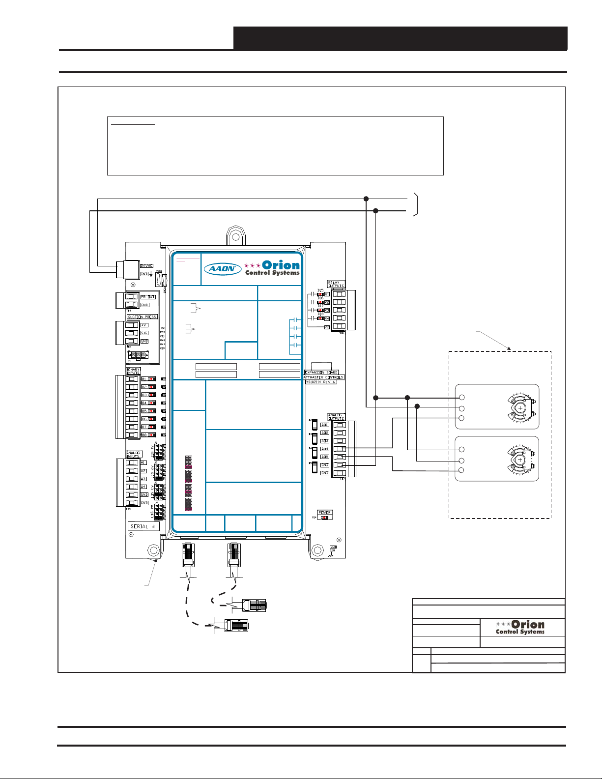
VCM-X Expansion Module Wiring
WARNING!!
Observe Polarity! All boards must be wired with GND-to-GND and 24VAC-to-24VAC. Failure
to observe polarity will result in damage to one or more of the boards. Expansion Modules
must be wired in such a way that the expansion modules and the controller are always
powered together. Loss of power to the expansion module will cause the controller to become
inoperative until power is restored to the expansion module.
Return Air Bypass
24 VAC
GND
24 VAC POWER
24 VAC POWER ONLY
ONLY
WARNING!POLARITY MUST BE
WARNING!
OBSERVED OR THE BOARD
POLARITY
WILL BE DAMAGED
MUST BE
OBSERVED OR
POLARITY
WARNING
OBSERVE
THE BOARD
WILL BE
DAMAGED
VCM-X Expansion Module
Orion No.:OE333-23-EM
PR OUT
TO VCM-X INPUT
OE333-23-EM-A VCM-X EXPANSION MODULE
GND
TERMINALS AI5 & GND
PR OUT
TO VCM-X INPUT
GND
TERMINALS AI5 & GND
SUCTION PRESSURE
+V
TRANSDUCER CONNECTION
SIG
FOR HVAC UNITS WITHOUT
GND
DIGITALCOMPRESSOR
SUCTION PRESSURE
+V
TRANSDUCER CONNECTION
SIG
FOR HVAC UNITS WITHOUT
GND
DIGITALCOMPRESSOR
RELAY1 = RELAY 3 =
RELAY2 = RELAY 4 =
IT IS SUGGESTED
RELAY1 = RELAY 3 =
THATYOU WRITE THE
DESCRIPTION OF
RELAY2 = RELAY 4 =
THE RELAYOUTPUTS
YOUARE USING IN
THE BOXES
IT IS SUGGESTED
PROVIDEDABOVE
THATYOU WRITE THE
WITHA PERMANENT
DESCRIPTION OF
MARKER (SHARPIE®)
THE RELAYOUTPUTS
YOUARE USING IN
THE BOXES
PROVIDEDABOVE
ANALOG INPUT
WITHA PERMANENT
JUMPER SETTINGS
MARKER (SHARPIE®)
MUST BE SETAS
SHOWN FOR
PROPER
ANALOG INPUT
OPERATION
JUMPER SETTINGS
MUST BE SETAS
SHOWN FOR
ANALOG INPUT
PROPER
JUMPER
OPERATION
SETTINGS
THERM
4-20mA
ANALOG INPUT
AI1
0-10V
JUMPER
0-5V
SETTINGS
THERM
THERM
4-20mA
4-20mA
AI2
AI1
0-10V
0-10V
0-5V
0-5V
THERM
THERM
4-20mA
4-20mA
AI3
AI2
0-10V
0-10V
0-5V
0-5V
THERM
THERM
4-20mA
4-20mA
AI4
AI3
0-10V
0-10V
0-5V
0-5V
THERM
4-20mA
AI4
0-10V
I2C
0-5V
EXPANSION
I2C
WattMaster Label
EXPANSION
www.aaon.com
BI1 = EMERGENCY SHUTDOWN - N.C. INPUT
= DIRTY FILTER - N.O. INPUT
BI2
= PROOF OF FLOW - N.O. INPUT
BI3
= REMOTE FORCED OCCUPIED - N.O. INPUT
BI4
= REMOTE FORCED HEATING - N.O. INPUT
BI5
BI1 = HOOD ON - N.O. INPUT
= REMOTE FORCED COOLING - N.O. INPUT
BI6
BI2
= DIRTY FILTER - N.O. INPUT
= HOOD ON - N.O. INPUT
BI7
BI3
= PROOF OF FLOW - N.O. INPUT
= REMOTE DEHUMIDIFICATION - N.O. INPUT
BI8
BI4
= REMOTE FORCED OCCUPIED - N.O. INPUT
BI5
= REMOTE FORCED HEATING - N.O. INPUT
NOTE:
BI6
= REMOTE FORCED COOLING - N.O. INPUT
ALL BINARY INPUTS MUSTBE 24 VAC ONLY.
BI7
= SMOKE DETECTOR - N.C. INPUT
BI8
= REMOTE DEHUMIDIFICATION - N.O. INPUT
AO1 = BUILDING PRESSURE CONTROL VFD OR
NOTE:
DAMPER ACTUATOR (0-10 OR 2-10 VDC)
ALL BINARY INPUTS MUSTBE 24 VAC ONLY.
= MODULATING HEATING SIGNAL
AO2
(0-10 VDC OR 2-10 VDC)
= MODULATING COOLING/DIGITALSCROLL
AO3
AO1 = BUILDING PRESSURE CONTROL VFD OR
SIGNAL (0-10 VDC, 2-10 VDC OR 1.5-5 VDC)
DAMPER ACTUATOR (0-10 OR 2-10 VDC)
= MODULATING HEATING SIGNAL
AO2
= RETURN AIR DAMPERACTUATOR
AO4
(0-10 VDC OR 2-10 VDC)
(0-10 VDC)
= MODULATING COOLING/DIGITALSCROLL
AO3
= RETURN AIR BYPASS DAMPERACTUATOR
AO5
SIGNAL (0-10 VDC, 2-10 VDC OR 1.5-5 VDC)
(0-10 VDC)
= RETURN AIR DAMPERACTUATOR
AO4
= GROUND FOR ANALOG OUTPUTS
GND
(0-10 VDC)
= GROUND FOR ANALOG OUTPUTS
GND
= RETURN AIR BYPASS DAMPERACTUATOR
AO5
(0-10 VDC)
AI1 = OUTDOOR AIR RH SENSOR (0-5 VDC)
= GROUND FOR ANALOG OUTPUTS
GND
AI2
= INDOOR AIR RH SENSOR (0-5 VDC)
= GROUND FOR ANALOG OUTPUTS
GND
A3
= ECONOMIZER FEEDBACK
I
AI4
= BUILDING STATIC PRESSURE (0-5 VDC)
AI1 = OUTDOOR AIR RH SENSOR (0-5 VDC)
GND
= GROUND FOR ANALOG INPUTS
AI2
= INDOOR AIR RH SENSOR (0-5 VDC)
GND
= GROUND FOR ANALOG INPUTS
AI3
= CO2 (0-10 VDC)
AI4
= BUILDING STATIC PRESSURE (0-5 VDC)
GND
= GROUND FOR ANALOG INPUTS
GND
I2C
= GROUND FOR ANALOG INPUTS
EXPANSION
EXPANSION
#LB102034-01
www.orioncontrols.com
AAON No.:
R69190
www.orioncontrols.com
RELAYCONTACT
RATING IS 1AMP
MAX @ 24 VAC
RELAYCONTACT
RELAY1
RATING IS 1AMP
MAX @ 24 VAC
RELAY2
RELAY1
RELAY3
RELAY2
RELAY4
RELAY3
RELAY
COMMON
RELAY4
RELAY
COMMON
WattMaster Label
#LB102034-01-A
Rev.: 1L
I2C
Belimo Actuator Wiring
Shown. Consult Factory
For Other Manufacturer
VCM
AO4
AO5
GND
10 VA Minimum Power
Required For
VCM-X Expansion Module
Wiring Instructions.
Return Air
Damper Actuator
(0-10 VDC)
1 COM
2 +
3Y1
1 COM
2 +
3Y1
Return Air Bypass
Damper Actuator
(0-10 VDC)
VCM-X
Expansion
Module
Modular Cable
Connect To Next Expansion
Board (When Used)
Connect To VCM-X E-BUS Controller
Figure 36: Return Air Bypass Wiring
VCM-X Component & Systems Wiring
Modular Cable
FILENAME
OVCMX-RA-BYP-Wr-1B.cdr
DATE:
05/15/15
PAGE
1 of 1
JOB NAME
S. Olson
BY:
DESCRIPTION:
VCM-X Expansion Module
Return Air Bypass Wiring
55
Page 56

VCM-X Expansion Module Wiring
EXP1
EXP1
EXP2
EXP2
12 Relay Expansion Module
WARNING!!
Observe Polarity! All boards must be wired with GND-to-GND and 24VAC-to-24VAC.
Failure to observe polarity will result in damage to one or more of the boards. Expansion
Modules must be wired in such a way that the expansion modules and the controller are
always powered together. Loss of power to the expansion module will cause the controller
to become inoperative until power is restored to the expansion module.
Modular Cable
Connect To Next Expansion Board
Modular Cable
(When Used)
24 VAC
OE358-23-12R
12-Relay
Expansion Module
POWER
24VAC
GND
EXP1
EXP2
RLY1
RLY2
RLY3
RLY4
RLY COM
MADE IN USA
24 VAC POWER ONLY
WARNING!POLARITY MUST BE
OBSERVED OR THE BOARD
WILLBE DAMAGED
OE358-23-12R-A 12 RELAYEXPANSION MODULE
RLY1 = RLY 7 =
RLY2 = RLY 8 =
RLY3 = RLY 9 =
RLY4 = RLY 10 =
RLY5 = RLY 11 =
RLY6 = RLY 12 =
NOTE:
IT IS RECOMMENDED THATYOU WRITE THE
DESCRIPTION OF THE RELAYOUTPUTS YOU
ARE CONNECTING TO THE RELAYEXPANSION
MODULE IN THE BOXES PROVIDEDABOVE
USING APERMANENT MARKER (SHARPIE)
FOR FUTURE REFERENCE.
J1
SET JUMPERAS
EXP1
SHOWN WHEN
THE 12 RELAY
EXP2
EXPANSION MODULE
IS USED
EXPANSION
ONLY
I2C
www.orioncontrols.com
®
EXP1
EXP2
WattMaster Label
#LB102043
J1
SET JUMPERAS
SHOWN WHEN BOTH
THE VCM EXPANSION
MODULE ANDTHE
RELAYEXPANSION
MODULE ARE USED
EXPANSION
15 VA Minimum Power
Required For
12 Relay Expansion
Module
Set Jumper As Shown
Below When Only The
12 Relay Expansion
Module Is Used
Set Jumper As
Shown Above When
Both The 12 Relay &
VCM-X Expansion
Module Are Used
R1
Connect To VCM-X E-BUS Controller
GND
Note:
All Relay Outputs Are Normally Open
And Rated For 24 VAC Power Only.
1 Amp Maximum Load.
Relay Output Contacts R1 Thru R12
May Be User-Configured For The
Following:
1 - Heating Stages
2 - Cooling Stages
3 - Warm-up Mode Command (VAV
Boxes)
4 - Reversing Valve (Heat Pumps)
5 - Reheat Control (Dehumidification)
6 - Exhaust Fan Interlock
7 - Preheater For Low Ambient Protection
8 - Alarm
9 - Override
10 - Occupied
11 - OA Damper
12 - Heat Wheel
13 - Emergency Heat
Note:
A Total Of 20 Relays Are Available
RELAY
I2C
EXPANSION BOARD
YS102228 REV 1
RLY COM
RLY COM
By Adding Relay Expansion Modules. All
Expansion Module Relay Outputs Are
-
User Configurable As Listed Above.
RLY5
RLY6
RLY7
RLY8
RLY9
RLY10
RLY11
RLY12
R5
Configurable Relay Output #5
R6
Configurable Relay Output #6
R7
Configurable Relay Output #7
R8
Configurable Relay Output #8
R9
Configurable Relay Output #9Configurable Relay Output #1
R10R2
Configurable Relay Output #10Configurable Relay Output #2
R11R3
Configurable Relay Output #11Configurable Relay Output #3
R12R4
Configurable Relay Output #12Configurable Relay Output #4
Figure 37: OE358-23-12R - 12 Relay Expansion Module Wiring
56
VCM-X Component & Systems Wiring
FILENAME
OVCMX-12RelayWire-1A.CDR
DATE:
01/11/13
PAGE
1 of 1
VCM-X Controller Wiring Detail
12 Relay Expansion Module
JOB NAME
S. Olson
DESCRIPTION:
Page 57

Connect To
VCM-X E-BUS Port
VCM-X Expansion Module Wiring
Airflow Monitoring Station
ANALOG INPU
JUMPER
SETTINGS
AI1 SET
AI1
AI2 SET AI3 SET
AI2
AI3
AI4
AI5
AI4 SET AI5 SET AI7 SET
AI7
THERM
4-20mA
AI1
0-10V
0-5V
THERM
4-20mA
AI2
0-10V
0-5V
THERM
4-20mA
AI3
0-10V
0-5V
THERM
EMERGENCY SHUTDOWN
4-20mA
AI4
0-10V
0-5V
THERM
4-20mA
AI5
0-10V
0-5V
THERM
4-20mA
AI7
0-10V
0-5V
ANALOG INPUTJUMPER SETTINGS
MUSTBE SET AS SHOWN FOR
PROPER OPERATION
STATIC
WattMaster Label
#LB102033-01
PRESSURE
VCM-X E-BUS Controller
24 VAC POWER ONLY
WARNING!POLARITY MUST BE OBSERVED
OR THE CONTROLLER WILLBE DAMAGED
I2C
EXPANSION
I2C DIGITAL
SENSOR
OE365-15-EBA
E-BUS Adapter Board
NET+
NETCOMM
NET+
NETCOMM
NET+
NETCOMM
Airflow Measurement
Digital Transmitter Terminals
For Supply Air CFM
(Set Address Switch To 11)
Airflow Measurement
Digital Transmitter Terminals
For Return Air CFM
(Set Address Switch To 10)
Airflow Measurement
Digital Transmitter Terminals
For Outdoor Air CFM
(Set Address Switch To 9)
HSSC Cable Connect To
HSSC Cable Connect To
VCM-X E-BUS Port
VCM-X E-BUS Port
JOB NAME
FILENAME
OVCMX-Airflow-Station-1A.cdr
S. Olson
PAGE
1 of 1
DATE:
05/15/15
Airflow Monitoring Station Wiring
BY:
DESCRIPTION:
VCM-X Expansion Module
Figure 38: OE365-15-EBA - EBTRON® GTC116 Series, GreenTrolTM GA-200-N Series, and Paragon
MicroTransEQ Series Air Flow Measurement Digital Transmitter Wiring
VCM-X Component & Systems Wiring
57
Page 58

VCM-X Expansion Module Wiring
Zone
Zone
58
VCM-X Component & Systems Wiring
Page 59

Modular & Non-Modular VAV/Zone Controller Wiring
Modular & Non-Modular
VAV/Zone Controller
Diagrams
VCM-X Component & Systems Wiring
59
Page 60
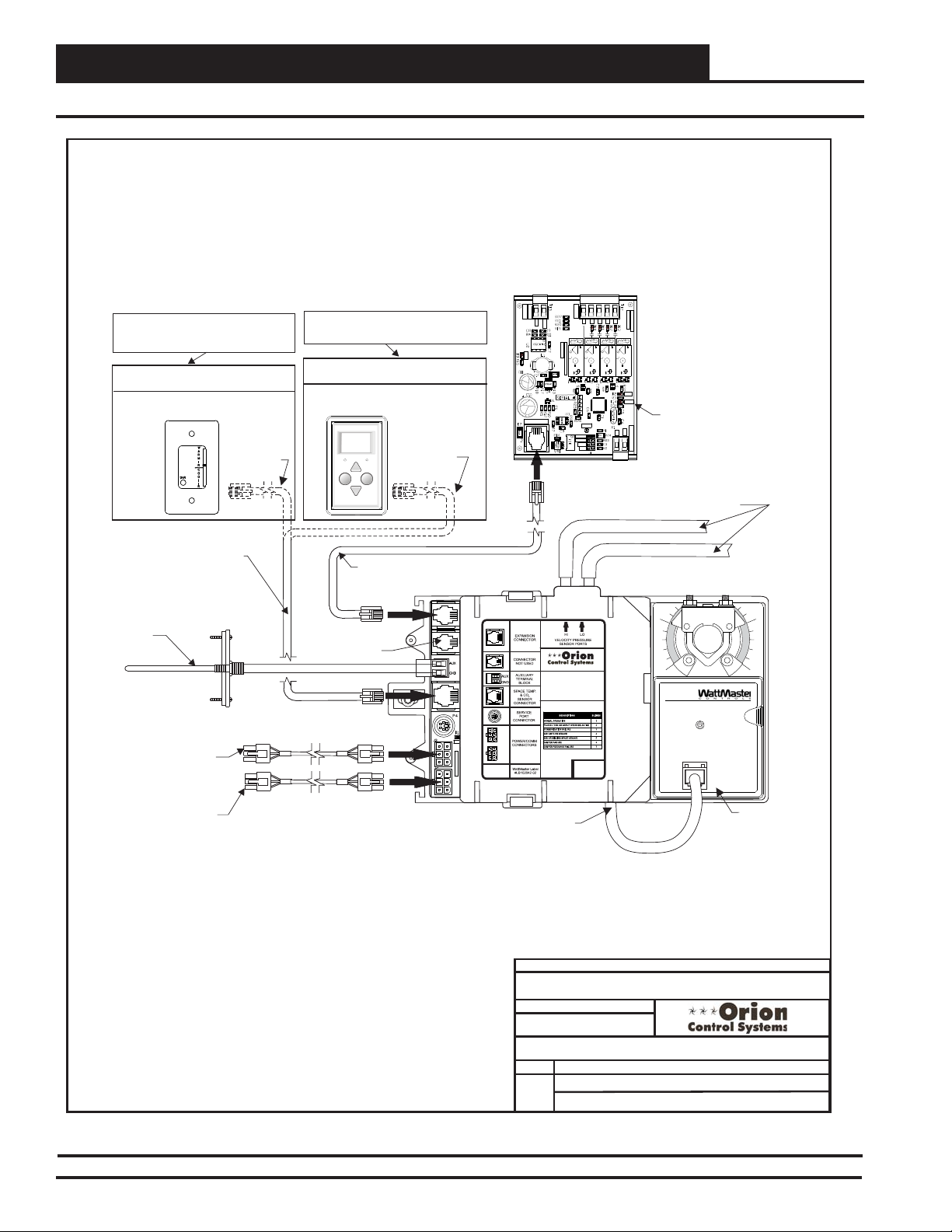
Zone
O
Modular & Non-Modular VAV/Zone Controller Wiring
Zone
Modular VAV/Zone Controller Actuator Package Wiring
OE325-01 Fan & Reheat
Expansion Module
(See Reheat Board Wiring For
Detailed Wiring Connections)
RELAYS
ANALOG
GND
RcR1R2R3R4
AOUT
MADEIN USA
WATMASTERCONTROLS INC.
VDE
SA
5A30VDC
CHINA
DC24V
G5Q-1A4
OMRON
VREF
THERM
4-20mA
0-10V
0-5V
Connect FRP Tubing (By Others) To Terminal
Unit Air Flow Pickup Tube Hi & Lo Ports
(P.I. VAV/Zone Controller Packages Only)
www.orioncontrols.com
OE744-31-VAVZ
P.I. VAV/ZONE
CONTROLLER ACTUATOR
PACKAGE
ZONEEXPANSION
YS102252REV 1
VDE
VDE
VDE
SA
SA
SA
5A30VDC
5A30VDC
5A30VDC
10A250VAC~
10A250VAC~
10A250VAC~
10A250VAC~
CHINA
CHINA
CHINA
DC24V
DC24V
DC24V
G5Q-1A4
OMRON
G5Q-1A4
OMRON
G5Q-1A4
OMRON
STAT
PIC18F4520
COMM
This Expansion Module Is
ANALOGINPUT
GND
AIN
Only Required For Single
Duct Terminal Units With
Reheat And All Fan
OE282
Terminal Units
Note: The Total Length Of Cable
Cannot Exceed 160 Feet.
Wiring When Using A Modular Sensor
OE210-02, OE211-02, OE212-02
Or OE213-02 Modular Room Sensor
FMRSC Cable
TSDRSC Or FMRSC Cable As Required.
Select Cable Depending On Sensor(s)
Used. See Notes Above For Details
Optional - Supply Air Temperature
Sensor. Only Required When The Orion
VCM-X Controller Is Not Installed On The
HVAC Unit Connected To The Terminal
Units.Locate In Ductwork Downstream Of
The Terminal Unit
Note: The Total Length Of Cable
Cannot Exceed 160 Feet.
Wiring When Using A Digital Room Sensor
OE217-00 / OE217-01
Digital Room Sensor
OVERRIDE ALARM
Display
Connector Not Used
With This Product
TSDRSC Cable
Override
Modular Expansion Cable
Supplied With OE325-01 Expansion Module
OUTPUT
PWR
EXPANSION IN
10
Power/Comm Cable From Previous
VAV/Zone Controller Actuator
Package, System Manager Or
Power/Comm Distribution Board
Power/Comm Cable To Next
VAV/Zone Controller Actuator
Package, System Manager Or
Power/Comm Distribution Board
REC
POWER/ CO
MM
Damper Actuator Cable
Damper Actuator
JOB NAME
FILENAME
ZCAP-MOD-Main-Wire-1A.CDR
DATE:
PAGE
1 of 1
01/16/13
OE742-31 & OE744-31 VAV/Zone Controller
S. Olson
DESCRIPTION:
Wiring DetailsActuator Package
Figure 39: OE742-31 & OE744-31 - Modular Zone Controller Actuator Package - P.I. & P.D. Wiring
60
VCM-X Component & Systems Wiring
Page 61

Non-Modular VAV/Zone Controller Actuator Package Wiring
Note: The Total Length Of Cable
Cannot Exceed 160 Feet.
Wiring When Using A Modular Sensor
OE210-02, OE211-02, OE212-02
Or OE213-02 Modular Room Sensor
TSDRSC Or FMRSC Cable As
Required. Select Cable
Depending On Sensor(s) Used.
See Notes Above For Details
Optional - Supply Air Temperature
Sensor. Only Required When The
Orion VCM-X Controller Is Not
Installed On The HVAC Unit
Connected To The Terminal Units.
Locate In Ductwork Downstream
Of The Terminal Unit
Wire To Previous And/Or Next VAV/Zone
Controller Actuator Package Or Device On The
Local Communications Loop Using 2 Conductor
Twisted Pair With Shield Cable Available From
WattMaster. All Communication Cable Used
Must Be Belden 82760 Or Its Equivalent.
Line
Voltage
Modular & Non-Modular VAV/Zone Controller Wiring
OE325-01 Fan & Reheat
Expansion Module
(See Reheat Board Wiring For
Detailed Wiring Connections)
RELAYS
ANALOG
GND
AOUT
MADEIN USA
WATMASTERCONTROLS INC.
VDE
SA
DC24V
G5Q-1A4
OMRON
THERM
4-20mA
0-10V
0-5V
Connect FRP Tubing (By Others) To Terminal
Unit Air Flow Pickup Tube Hi & Lo Ports
(P.I. VAV/Zone Controller Packages Only)
www.orioncontrols.com
OE744-32-VAVZ
P.I. VAV/ZONE
CONTROLLERACTUATOR
PACKAGE
RcR1R2R3R4
VDE
SA
5A30VDC
5A30VDC
10A250VAC~
10A250VAC~
CHINA
CHINA
DC24V
G5Q-1A4
OMRON
PIC18F4520
VREF
ZONEEXPANSION
YS102252REV1
VDE
VDE
SA
SA
5A30VDC
5A30VDC
10A250VAC~
10A250VAC~
CHINA
CHINA
DC24V
DC24V
G5Q-1A4
OMRON
G5Q-1A4
OMRON
STAT
COMM
This Expansion Module Is
ANALOGINPUT
GND
AIN
Only Required For Single
Duct Terminal Units With
Reheat And All Fan
OE282
Terminal Units
10
Damper Actuator
FMRSC Cable
Note: The Total Length Of Cable
Cannot Exceed 160 Feet.
Wiring When Using A Digital Room Sensor
OE217-00 / OE217-01
Digital Room Sensor
OVERRIDE ALARM
Display
Connector Not Used
With This Product
TSDRSC Cable
Override
Modular Expansion Cable
Supplied With OE325-01 Expansion Module
TB2
24VAC
GND
TB3
T
SHLD
R
24VAC
GND
STAT
24 VAC
GND
WattMaster Label
#LB102042-06
T
SHLD
R
REC
Damper Actuator Cable
OUTPUT
PWR
EXPANSION IN
Rev. 01A
24 VAC Transformer. Size As
Required For Number Of
WARNING:
When Multiple VAV/Zone Controller
Actuator Packages Are Powered
From A Single Transformer Polarity
Must Be Observed Or Damage To
The Controllers Will Result.
Controllers Connected. Each
VAV/Zone Controller Actuator
Package Requires 6 VA Minimum.
JOB NAME
FILENAME
ZCAP-NM-Main-Wire-1A.CDR
S. Olson
DESCRIPTION:
Wiring DetailsActuator Package
PAGE
1 of 7
DATE:
01/16/13
OE742-32 & OE744-32 VAV/Zone Controller
Figure 40: OE742-32 & OE744-32 - Non-Modular Zone Controller Actuator Package - P.I. & P.D. Wiring
VCM-X Component & Systems Wiring
61
Page 62

Zone
FILENAME
DATE:
B. Crews
DESCRIPTION:
PAGE
DRAWN BY:
JOB NAME
1 of 6
WattMaster Part #OE325-01
w/ Modular Cable
Supplied by WattMaster
Mounted by Others
Expansion Module
WattMaster Part #OE325-01
w/ Modular Cable
Supplied by WattMaster
Mounted by Others
Expansion Module
WattMaster Part #OE325-01
w/ Modular Cable
Supplied by WattMaster
Mounted by Others
Expansion Module
24VAC
RC
RC
RC
R2
R1
R1
R2
R3
R3
24VAC
COM
COM
24 VAC Transformer Supplied
& Wired by Others. Size For
Required Contactor(s) Load.
24 VAC Transformer Supplied
& Wired by Others. Size For
Required Contactor(s) Load.
WattMaster Part # BK000047
Snaptrack Supplied by WattMaster
Mounted by Others. Remove Control
Board from Snaptrack & Mount
Snaptrack on Box
WattMaster Part # BK000047
Snaptrack Supplied by WattMaster
Mounted by Others. Remove Control
Board from Snaptrack & Mount
Snaptrack on Box
WattMaster Part # BK000047
Snaptrack Supplied by WattMaster
Mounted by Others. Remove Control
Board from Snaptrack & Mount
Snaptrack on Box
Connect To VAV/Zone Controller
Using Modular Cable Supplied
By WattMaster
Connect To VAV/Zone Controller
Using Modular Cable Supplied
By WattMaster
Connect To VAV/Zone Controller
Using Modular Cable Supplied
By WattMaster
24VAC
COM
Fan Relay
R1
C1
C1
R1
1st Stage Heat Contactor
1st Stage Heat Contactor
Fan Relay
2nd Stage Heat Contactor
2nd Stage Heat Contactor
3rd Stage Heat Contactor
3rd Stage Heat Contactor
C2
C2
C3
C3
Typical Wiring for
Single Duct Terminal
Typical Wiring for
Fan Terminal Unit
Typical Wiring for
Fan Terminal
With Electric Heat
Note: 3 Stage Heating is Attained by Sizing All 3
Heating Elements For Equal KW Output. Each
Element Should be Sized for 1/3 of the Total KW
Output Required. ToAchieve 3 Stage Heating the
System would be Configured to Energize Contactor
C1 for First Stage Heat. For 2nd Stage Heat the
System Would be Configured to De-energize
Contactor C1 and Energize Contactor C2 & C3. For
3rd Stage Heat the System Would be Configured to
Leave Contactor C2 & C3 Energized and also
Energize Contactor C1.
Note: 3 Stage Heating is Attained by Sizing All 3 Heating
Elements For Equal KW Output. Each Element Should be
Sized for 1/3 of the Total KW Output Required. To Achieve 3
Stage Heating the System would be Configured to Energize
Contactor C1 for First Stage Heat. For 2nd Stage Heat the
System Would be Configured to De-energize Contactor C1
and Energize Contactor C2 & C3. For 3rd Stage Heat the
System Would be Configured to Leave Contactor C2 & C3
Energized and also Energize Contactor C1.
24 VAC Contactor(s)
Supplied & Wired By Others.
1 Amp Max. Load Each
24 VAC Fan Relay & Contactor(s) Supplied &
Wired By Others. 1 Amp Max. Load Each
24 VAC Transformer Supplied
& Wired by Others. Size For
Required Fan Relay Load.
24 VAC Fan Relay Supplied & Wired
By Others. 1 Amp Max. Load
ZONEEXPANSION
YS102252REV 1
WATMASTERCONTROLS INC.
MADEIN USA
Rc
R1
R2
R3
R4
AOUT
GND
RELAYS
ANALOG
OUTPUT
STAT
THERM
4-20mA
0-10V
0-5V
GND
AIN
ANALOG INPUT
VREF
EXPANSION IN
PWR
PIC18F4520
10A250VAC~
5A30VDC
SA
VDE
G5Q-1A4
OMRON
DC24V
CHINA
10A250VAC~
5A30VDC
SA
VDE
G5Q-1A4
OMRON
DC24V
CHINA
10A250VAC~
5A30VDC
SA
VDE
G5Q-1A4
OMRON
DC24V
CHINA
10A250VAC~
5A30VDC
SA
VDE
G5Q-1A4
OMRON
DC24V
CHINA
COMM
ZCAP-Exp-Mod-Wire-1A.CDR
01/16/12
VAV/Zone Controller Actuator Packages
Wiring DetailsOE325-01 Expansion Module
Modular & Non-Modular VAV/Zone Controller Wiring
Zone
Expansion Module Wiring
Figure 41: OE325-01 Expansion Module Wiring
62
VCM-X Component & Systems Wiring
Page 63

Modular & Non-Modular VAV/Zone Controller Wiring
Expansion Module Wiring
Connect To Zone/VAV Controller
With Modular Cable
Remove Control Board
from Snaptrack & Mount
Snaptrack on Box
Connect To Zone/VAV Controller
With Modular Cable
Remove Control Board
from Snaptrack & Mount
Snaptrack on Box
EXPANSION IN
OMRON
SA
G5Q-1A4
COMM
DC24V
5A30VDC
CHINA
10A250VAC~
OMRON
SA
G5Q-1A4
DC24V
OMRON
G5Q-1A4
DC24V
OMRON
G5Q-1A4
DC24V
5A30VDC
CHINA
10A250VAC~
SA
5A30VDC
CHINA
10A250VAC~
SA
5A30VDC
CHINA
10A250VAC~
PIC18F4520
STAT
THERM
4-20mA
0-10V
0-5V
VREF
AIN
GND
ANALOG INPUT
WattMaster Part #OE325-01
Relay Expansion Board
GND
GND
AOUT
Rc
R1
R2
R3
R4
OUTPUT
ANALOG
RELAYS
YS102252REV 1
ZONEEXPANSION
AOUT
0-10 VDC Signal
_
0-10 VDC
HWV
+
PWR
MADEIN USA
WATMASTERCONTROLS INC.
VDE
VDE
VDE
VDE
COM
24VAC
24 VAC Transformer
Supplied & Wired by
Others. Size For
Required HW Valve Load.
0-10 VDC Modulating
Hot Water Valve Supplied
& Wired By Others
Typical Wiring For
Single Duct Terminal
With Modulating Hot
Water Heat
0-10 VDC Modulating Hot Water
Valve Supplied & Wired By Others
GND
GND
AOUT
Rc
R1
R2
R3
R4
OUTPUT
ANALOG
RELAYS
YS102252REV 1
ZONEEXPANSION
AOUT
0-10 VDC Signal
RC
R1
24VAC
COM
_
0-10 VDC
HWV
Fan Relay
+
PWR
MADEIN USA
WATMASTERCONTROLS INC.
VDE
VDE
VDE
VDE
COM
24VAC
24 VAC Transformer
Supplied & Wired by
Others. Size For
Required HW Valve Load.
24 VAC Transformer Supplied
& Wired by Others. Size For
Required Fan Relay Load.
R1
24 VAC Fan Relay
Supplied & Wired By
Others. 1 Amp Max.
Load.
Typical Wiring For
Fan Terminal With
Modulating Hot
Water Heat
Figure 42: OE325-01 Expansion Module Wiring
VCM-X Component & Systems Wiring
FILENAME
ZCAP-Exp-Mod-Wire-1B.CDR
DATE: 08/15/14
PAGE
2 of 6
VAV/Zone Controller Actuator Packages
JOB NAME
DRAWN BY:
DESCRIPTION:
B. Crews
Wiring DetailsOE325-01 Expansion Module
63
Page 64
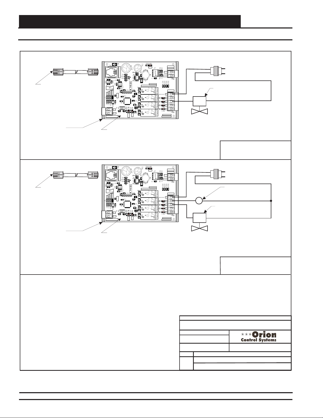
Zone
Modular & Non-Modular VAV/Zone Controller Wiring
Zone
Expansion Module Wiring
Connect To VAV/Zone Controller
Using Modular Cable Supplied
By WattMaster
WattMaster Part # BK000047
Snaptrack Supplied by WattMaster
Mounted by Others. Remove
Control Board from Snaptrack &
Mount Snaptrack on Box
Connect To VAV/Zone Controller
Using Modular Cable Supplied
By WattMaster
WattMaster Part # BK000047
Snaptrack Supplied by WattMaster
Mounted by Others. Remove
Control Board from Snaptrack &
Mount Snaptrack on Box
EXPANSION IN
OMRON
G5Q-1A4
THERM
4-20mA
0-10V
0-5V
VREF
AIN
GND
ANALOG INPUT
WattMaster Part #OE325-01
Expansion Module
w/ Modular Cable
Supplied by WattMaster
Mounted by Others
EXPANSION IN
THERM
4-20mA
0-10V
0-5V
VREF
AIN
GND
ANALOG INPUT
WattMaster Part #OE325-01
Expansion Module
w/ Modular Cable
Supplied by WattMaster
Mounted by Others
DC24V
OMRON
G5Q-1A4
DC24V
PIC18F4520
OMRON
G5Q-1A4
DC24V
OMRON
G5Q-1A4
DC24V
COMM
STAT
OMRON
G5Q-1A4
DC24V
OMRON
G5Q-1A4
DC24V
PIC18F4520
OMRON
G5Q-1A4
DC24V
OMRON
G5Q-1A4
DC24V
COMM
STAT
PWR
MADEIN USA
WATMASTERCONTROLS INC.
SA
VDE
5A30VDC
CHINA
10A250VAC~
SA
VDE
5A30VDC
CHINA
10A250VAC~
SA
VDE
5A30VDC
CHINA
10A250VAC~
SA
VDE
5A30VDC
CHINA
10A250VAC~
OUTPUT
ANALOG
GND
AOUT
RELAYS
RC
Rc
R1
R2
R2
R3
R4
YS102252REV 1
ZONEEXPANSION
24VAC
COM
HWV
24 VAC Transformer Supplied
& Wired by Others. Size For
Required HW Valve Load.
24 VAC 2 Position HW Valve
Supplied & Wired By Others. 1
Amp Max. Load.
Typical Wiring for
Single Duct Terminal
With 2 Position HW Valve
PWR
MADEIN USA
WATMASTERCONTROLS INC.
SA
VDE
5A30VDC
CHINA
10A250VAC~
SA
VDE
5A30VDC
CHINA
10A250VAC~
SA
VDE
5A30VDC
CHINA
10A250VAC~
SA
VDE
5A30VDC
CHINA
10A250VAC~
OUTPUT
ANALOG
GND
AOUT
RELAYS
RC
Rc
R1
R1
R2
R2
R3
R4
YS102252REV 1
ZONEEXPANSION
24VAC
COM
Fan Relay
R1
HWV
24 VAC Transformer Supplied
& Wired by Others. Size For
Required HW Valve & Fan Relay
Load.
24 VAC Fan Relay Supplied &
Wired By Others. 1 Amp Max.
Load.
24 VAC 2 Position HW Valve
Supplied & Wired By Others. 1
Amp Max. Load.
Figure 43: OE325-01 Expansion Module Wiring
64
Typical Wiring for
Fan Terminal With
2 Position HW Valve
JOB NAME
FILENAME
ZCAP-Exp-Mod-Wire-1A.CDR
DATE: 01/16/13
PAGE
3 of 6
VAV/Zone Controller Actuator Packages
DRAWN BY:
DESCRIPTION:
B. Crews
Wiring DetailsOE325-01 Expansion Module
VCM-X Component & Systems Wiring
Page 65

Connect To VAV/Zone Controller
Using Modular Cable Supplied
By WattMaster
WattMaster Part # BK000047
Snaptrack Supplied by WattMaster
Mounted by Others. Remove
Control Board from Snaptrack &
Mount Snaptrack on Box
Connect To VAV/Zone Controller
Using Modular Cable Supplied
By WattMaster
WattMaster Part # BK000047
Snaptrack Supplied by WattMaster
Mounted by Others. Remove
Control Board from Snaptrack &
Mount Snaptrack on Box
Modular & Non-Modular VAV/Zone Controller Wiring
Expansion Module Wiring
OUTPUT
EXPANSION IN
OMRON
G5Q-1A4
THERM
4-20mA
0-10V
0-5V
VREF
AIN
GND
ANALOG INPUT
WattMaster Part #OE325-01
Expansion Module
w/ Modular Cable
Supplied by WattMaster
Mounted by Others
EXPANSION IN
THERM
4-20mA
0-10V
0-5V
VREF
AIN
GND
ANALOG INPUT
WattMaster Part #OE325-01
Expansion Module
w/ Modular Cable
Supplied by WattMaster
Mounted by Others
DC24V
CHINA
OMRON
G5Q-1A4
DC24V
PIC18F4520
CHINA
OMRON
G5Q-1A4
DC24V
CHINA
OMRON
G5Q-1A4
DC24V
COMM
STAT
CHINA
OMRON
G5Q-1A4
DC24V
CHINA
OMRON
G5Q-1A4
DC24V
PIC18F4520
CHINA
OMRON
G5Q-1A4
DC24V
CHINA
OMRON
G5Q-1A4
DC24V
COMM
STAT
CHINA
SA
5A30VDC
10A250VAC~
SA
5A30VDC
10A250VAC~
SA
5A30VDC
10A250VAC~
SA
5A30VDC
10A250VAC~
SA
5A30VDC
10A250VAC~
SA
5A30VDC
10A250VAC~
SA
5A30VDC
10A250VAC~
SA
5A30VDC
10A250VAC~
PWR
GND
AOUT
MADEIN USA
WATMASTERCONTROLS INC.
VDE
Rc
R1
VDE
R2
R3
VDE
R4
VDE
PWR
GND
AOUT
MADEIN USA
WATMASTERCONTROLS INC.
VDE
Rc
R1
VDE
R2
R3
VDE
R4
VDE
GND
ANALOG
AOUT
RELAYS
YS102252REV 1
ZONEEXPANSION
SCR
0-10 VDC SCR Electric Heat
Controller Supplied & Wired
By Others
Typical Wiring For
Single Duct Terminal
With SCR Electric Heat
GND
OUTPUT
ANALOG
AOUT
0-10 VDC
RELAYS
RC
R1
YS102252REV 1
ZONEEXPANSION
24VAC
COM
Fan Relay
SCR
0-10 VDC SCR Electric Heat
Controller Supplied & Wired
By Others
24 VAC Transformer Supplied
& Wired by Others. Size For
Required Fan Relay Load.
R1
24 VAC Fan Relay
Supplied & Wired By
Others. 1 Amp Max.
Load.
Typical Wiring For
Fan Terminal With
SCR Electric Heat
Figure 44: OE325-01 Expansion Module Wiring
VCM-X Component & Systems Wiring
FILENAME
ZCAP-Exp-Mod-Wire-1A.CDR
DATE 01/16/13:
PAGE
4 of 6
VAV/Zone Controller Actuator Packages
JOB NAME
DRAWN BY:
DESCRIPTION:
B. Crews
Wiring DetailsOE325-01 Expansion Module
65
Page 66
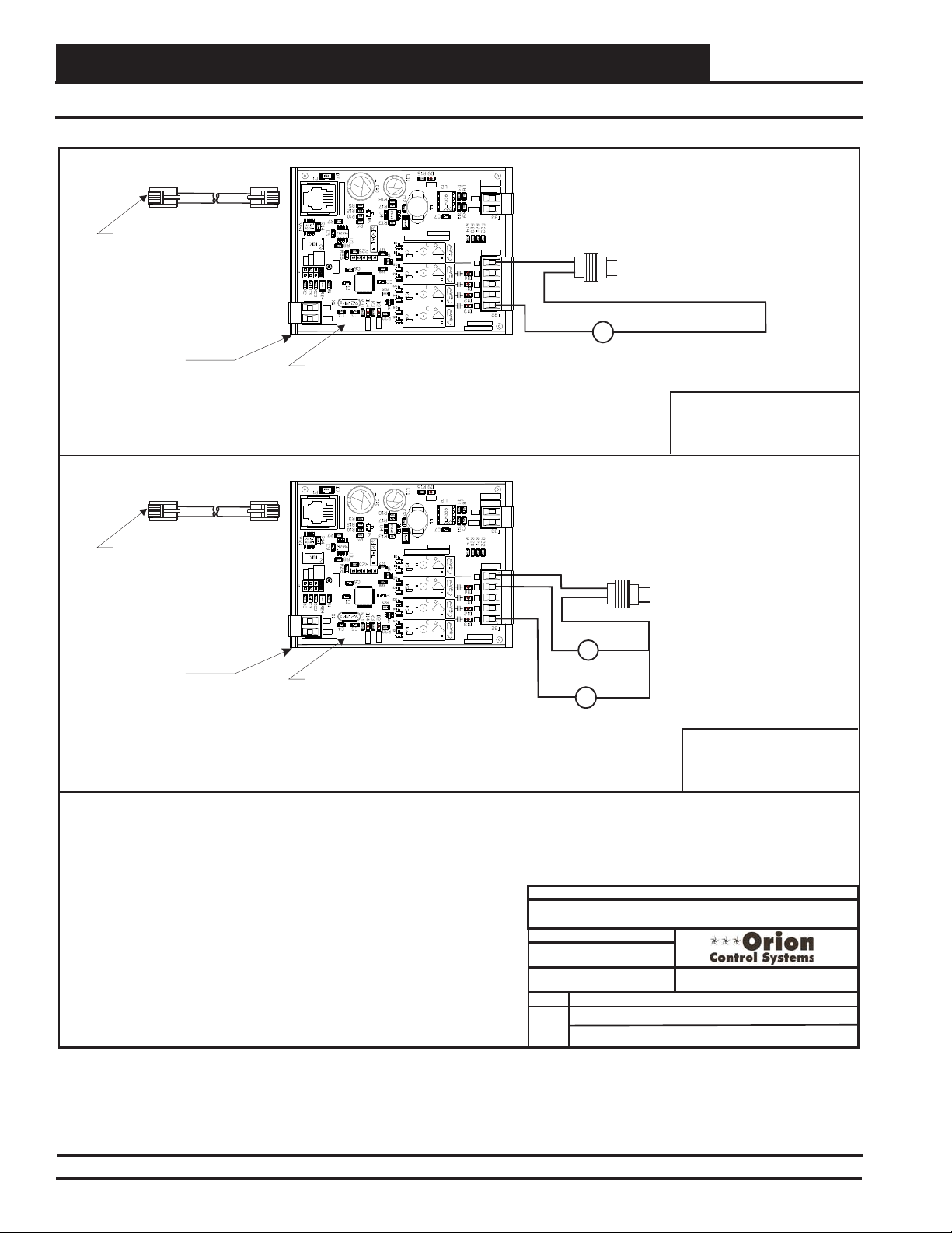
Zone
Modular & Non-Modular VAV/Zone Controller Wiring
Zone
Expansion Module Wiring
Connect To VAV/Zone Controller
Using Modular Cable Supplied
By WattMaster
WattMaster Part # BK000047
Snaptrack Supplied by WattMaster
Mounted by Others. Remove Control
Board from Snaptrack & Mount
Snaptrack on Box
Connect To VAV/Zone Controller
Using Modular Cable Supplied
By WattMaster
WattMaster Part # BK000047
Snaptrack Supplied by WattMaster
Mounted by Others. Remove Control
Board from Snaptrack & Mount
Snaptrack on Box
EXPANSION IN
OMRON
G5Q-1A4
THERM
4-20mA
0-10V
0-5V
VREF
AIN
GND
ANALOG INPUT
WattMaster Part #OE325-01
Expansion Module
w/ Modular Cable
Supplied by WattMaster
Mounted by Others
EXPANSION IN
THERM
4-20mA
0-10V
0-5V
VREF
AIN
GND
ANALOG INPUT
WattMaster Part #OE325-01
Expansion Module
w/ Modular Cable
Supplied by WattMaster
Mounted by Others
DC24V
CHINA
OMRON
G5Q-1A4
DC24V
PIC18F4520
CHINA
OMRON
G5Q-1A4
DC24V
CHINA
OMRON
G5Q-1A4
DC24V
COMM
STAT
CHINA
OMRON
G5Q-1A4
DC24V
CHINA
OMRON
G5Q-1A4
DC24V
PIC18F4520
CHINA
OMRON
G5Q-1A4
DC24V
CHINA
OMRON
G5Q-1A4
DC24V
COMM
STAT
CHINA
SA
5A30VDC
10A250VAC~
SA
5A30VDC
10A250VAC~
SA
5A30VDC
10A250VAC~
SA
5A30VDC
10A250VAC~
SA
5A30VDC
10A250VAC~
SA
5A30VDC
10A250VAC~
SA
5A30VDC
10A250VAC~
SA
5A30VDC
10A250VAC~
PWR
MADEIN USA
WATMASTERCONTROLS INC.
VDE
VDE
VDE
VDE
OUTPUT
ANALOG
GND
AOUT
RELAYS
RC
Rc
R1
R2
R3
R4
YS102252REV 1
ZONEEXPANSION
24VAC
COM
R4
Auxiliary Electric Heat Contactor
24 VAC Auxiliary Electric Heat
Contactor Supplied & Wired
By Others. 1 Amp Max. Load.
24 VAC Transformer Supplied
& Wired by Others. Size For
Required Auxiliary Electric Heat
Contactor Load.
C1
Typical Wiring For
Single Duct Terminal
With Auxiliary
Electric Heat
PWR
MADEIN USA
WATMASTERCONTROLS INC.
VDE
VDE
VDE
VDE
OUTPUT
ANALOG
GND
AOUT
RELAYS
RC
Rc
R1
R1
R2
R3
R4
R4
YS102252REV 1
ZONEEXPANSION
24VAC
COM
Fan Relay
R1
Auxiliary Electric
Heat Contactor
24 VAC Transformer Supplied
& Wired by Others. Size For
Required Fan Relay & Auxiliary
Electric Heat Contactor Load.
24 VAC Fan Relay & Auxilliary
Electric Heat Contactor
Supplied & Wired By Others. 1
Amp Max. Load.
C1
Typical Wiring For
Fan Terminal With
Auxiliary Electric Heat
Figure 45: OE325-01 Expansion Module Wiring
66
JOB NAME
FILENAME
ZCAP-Exp-Mod-Wire-1A.CDR
DATE: 01/16/13
PAGE
5 of 6
VAV/Zone Controller Actuator Packages
DRAWN BY:
DESCRIPTION:
B. Crews
Wiring DetailsOE325-01 Expansion Module
VCM-X Component & Systems Wiring
Page 67

Modular & Non-Modular VAV/Zone Controller Wiring
Expansion Module Wiring
Connect To VAV/Zone Controller
Using Modular Cable Supplied
By WattMaster
WattMaster Part # BK000047
Snaptrack Supplied by WattMaster
Mounted by Others. Remove Control
Board from Snaptrack & Mount
Snaptrack on Box
Connect To VAV/Zone Controller
Using Modular Cable Supplied
By WattMaster
WattMaster Part # BK000047
Snaptrack Supplied by WattMaster
Mounted by Others. Remove Control
Board from Snaptrack & Mount
Snaptrack on Box
EXPANSION IN
OMRON
SA
G5Q-1A4
THERM
4-20mA
0-10V
0-5V
VREF
AIN
GND
ANALOG INPUT
WattMaster Part #OE325-01
Relay Expansion Board
w/ Modular Cable
Supplied by WattMaster
Mounted by Others
EXPANSION IN
THERM
4-20mA
0-10V
0-5V
VREF
AIN
GND
ANALOG INPUT
WattMaster Part #OE325-01
Relay Expansion Board
w/ Modular Cable
Supplied by WattMaster
Mounted by Others
DC24V
5A30VDC
CHINA
10A250VAC~
OMRON
SA
G5Q-1A4
DC24V
OMRON
G5Q-1A4
DC24V
OMRON
G5Q-1A4
DC24V
OMRON
G5Q-1A4
DC24V
OMRON
G5Q-1A4
DC24V
OMRON
G5Q-1A4
DC24V
OMRON
G5Q-1A4
DC24V
5A30VDC
CHINA
10A250VAC~
SA
5A30VDC
CHINA
10A250VAC~
SA
5A30VDC
CHINA
10A250VAC~
SA
5A30VDC
CHINA
10A250VAC~
SA
5A30VDC
CHINA
10A250VAC~
SA
5A30VDC
CHINA
10A250VAC~
SA
5A30VDC
CHINA
10A250VAC~
PIC18F4520
COMM
STAT
PIC18F4520
COMM
STAT
PWR
MADEIN USA
WATMASTERCONTROLS INC.
VDE
VDE
VDE
VDE
24 VAC 2 Position
Auxiliary HW Valve
Supplied & Wired By
Others. 1 Amp Max. Load
PWR
MADEIN USA
WATMASTERCONTROLS INC.
VDE
VDE
VDE
VDE
24 VAC 2 Position
Auxiliary HW Valve
Supplied & Wired By
Others. 1 Amp Max. Load
OUTPUT
ANALOG
GND
AOUT
RELAYS
Rc
R1
R2
R3
R4
YS102252REV 1
ZONEEXPANSION
OUTPUT
ANALOG
GND
AOUT
RELAYS
Rc
R1
R2
R3
R4
YS102252REV 1
ZONEEXPANSION
24VAC
COM
HWV
24VAC
COM
Fan Relay
R1
HWV
24 VAC Transformer Supplied
& Wired by Others. Size For
Required Auxiliary HW Valve Load.
Typical Wiring For Single Duct
Terminal With Two Position
Auxiliary Hot Water Heat
24 VAC Transformer Supplied
& Wired by Others. Size For
Required Fan Relay & Auxiliary
Hot Water Valve Load
24 VAC Fan Relay Supplied
& Wired By Others. 1 Amp
Max. Load.
Typical Wiring For Fan
Terminal With Two Position
Auxiliary Hot Water Heat
Figure 46: OE325-01 Expansion Module Wiring
VCM-X Component & Systems Wiring
FILENAME
ZCAP-Exp-Mod-Wire-1A.CDR
DATE: 01/16/13
PAGE
6 of 6
VAV/Zone Controller Actuator Packages
JOB NAME
DRAWN BY:
DESCRIPTION:
B. Crews
Wiring DetailsOE325-01 Expansion Module
67
Page 68

Zone
Modular & Non-Modular VAV/Zone Controller Wiring
Zone
Slaved Zone Wiring
OE520-XX-M, OE736-01, OE742-31
EXPANSION D'STAT SPACESENSOR
EPROM
485
DRV
REC
POWER/ COMM
PWR
STAT
WATTMASTER CONTROLS INC
OE523, OE738, OE282-03
PAL
24 Mhz
PROCESSOR
MADE IN USA
SLAVED- ZONE ACTUATOR #2
EEPROM
ADDRESS
OFF ON
WDOG
AIRFLOW
LOW(VVT)
VELOCITY
HI(VAV)
(WHEN USED)
ACTUATOR
93C66
1 10 0
OE282
MODULAR CABLE
OE523, OE738, OE282-03
MODULAR CABLE
10
HZ000095
SLAVED-ZONE ACTUATOR #1
OE267
(PL101824) BYPASS AND
SLAVE INTERFACE CARD
CLOSE
OPEN
TB1
GND
FDBK
CLOSE
OPEN
GND
PJ2
FROM ZONE
CONTROLLER
TB2
PJ1
TOACTUATOR
LD2
OPEN
SLAVE INTERFACE
YS101824
LD1
CLOSE
BYPASSAND
(PL101824) BYPASS AND
SLAVE INTERFACE CARD
TOACTUATOR
BYPASSAND
SLAVE INTERFACE
YS101824
PJ1
GND
OPEN
TB2
CLOSE
OPEN
CLOSE
FROM ZONE
CONTROLLER
PJ2
LD2
LD1
FDBK
GND
TB1
OPEN
CLOSE
OE282 OE282
MODULAR
CABLE
HZ000095
NOT USED FOR
THIS APPLICATION
(PL101824) BYPASS AND
SLAVE INTERFACE CARD
TOACTUATOR
BYPASSAND
SLAVE INTERFACE
YS101824
PJ1
GND
OPEN
TB2
CLOSE
OPEN
CLOSE
FROM ZONE
CONTROLLER
PJ2
LD2
LD1
FDBK
GND
TB1
OPEN
CLOSE
ZCAP-ZoneSlaveWire1B.CDR
DATE:
PAGE
1 of 1
MODULAR
CABLE
HZ000095
NOT USED FOR
THIS APPLICATION
JOB NAME
FILENAME
08/15/2014
DRAWN BY:
DESCRIPTION:
VAV/Zone Controller Actuator Packages
B. Crews
Wiring DetailsOE267 Slaved Zone Damper
Figure 47: Slaved Zone Wiring
68
VCM-X Component & Systems Wiring
Page 69

Communication Devices
Communication Devices
Diagrams
VCM-X Component & Systems Wiring
69
Page 70

Communication Devices
System Manager Stand-Alone Wiring
Modular System Manager SD
Back View
GB
4
NOTE: If Desired A Power/Comm Board As
Used With The Networked System Can Be
Installed And Wired Instead Of Using The
Pigtail Cable Wiring Shown Below. See The
Networked System Wiring Diagram For
Details.
NOTE: For Stand-Alone
Installations (No CommLink
or MiniLink), All TERM
Jumpers Must Be ON.
For All Applications With
CommLink(s) Or MiniLink(s),
All Jumpers Must Be OFF.
Use Supplied Modular Cable
With Stripped Ends For
Connection To Terminal Block
And Transformer
WHITE (T)
DRAIN WIRE (SHLD)
BLACK (R)
RED (24 VAC)
BROWN (GND)
GREEN (GND)
Class 2 Transformer
Rated For 6 VA Minimum
T
SHLD
R
Controller Board
JOB NAME
FILENAME
O-ModSystemMgr-ModPigtail1E.cdr
BY:
DATE:
PAGE
1 of 1
09/23/2013
OE392-12 Modular System Manager
S. Olson
DESCRIPTION:
Wiring DetailsStand-Alone
Figure 48: OE392-12 Modular System Manager Stand-Alone Wiring
VCM-X Component & Systems Wiring70
Page 71

Communication Devices
System Manager Wiring Details For Using The Pigtail
01/16/13
Notes:
1.) All wiring to be in accordance with local and national electrical codes
and specifications.
DATE:
DESCRIPTION:
PAGE
DRAWN BY:
Component Wiring Diagram
SysMgrPigtail1C.CDR
OE392-12 Modular System Manager
1 of 1
1.) All wiring to be in accordance with local and national electrical codes
and specifications.
2.) All modular power/comm cables are to be WattMaster part
number PCC-xx or PCCE-xx cables.
Notes:
B. Crews
Notes:
1.) All wiring to be in accordance with local and national electrical codes
and specifications.
WHITE (T)
BLACK (R)
RED (24 VAC)
BROWN (GND)
GREEN (GND)
Drain Wire (Shld)
LINE
VOLTAGE
LINE VOLTAGE
2-Conductor Shielded
18-Gauge
Communications Wire
FILENAME
JOB NAME
OE392-12 Modular System
Manager SD
Back of Front Cover
Handy Box, Conduit,
Fittings, Wire Nuts,
Butt Splices Etc.,
(By Others)
Controller Board
T
SHLD
R
HZ000121
Modular Pigtail Cable
Supplied With System Manager
Class 2 Transformer
Rated For 6 VA Minimum
(By Others)
05/18/15
DATE:
By: S. Olson
4
GB
System Manager Modular Cable Pigtail - Wiring Detail
Figure 49: OE392-12 Modular System Manager SD Cable Pigtail - Wiring Detail
VCM-X Component & Systems Wiring
71
Page 72

Communication Devices
System Manager Networked Wiring
Modular System Manager SD
Back View
GB
4
All Modular Power/Comm
Cables Are To Be
WattMaster Part Number
PCC-xx Or PCCE-xx
Cables.
NOTE: For Stand-Alone
Installations (No CommLink
or MiniLink), All TERM
Jumpers Must Be ON.
For All Applications With
CommLink(s) Or MiniLink(s),
All Jumpers Must Be OFF.
Power/Comm Cables To
Power/Comm
Distribution
Board, MiniLink Polling Device
Or VAV/Zone Controllers On
Local Loop.
Figure 50: OE392-12 Modular System Manager SD Networked Wiring
JOB NAME
FILENAME
O-ModSystemMgr-ModConnect-1C.cdr
BY:
PAGE
1 of 1
DATE:
05/15/15
OE392-12 Modular System Manager
S. Olson
DESCRIPTION:
Wiring DetailsNetworked
VCM-X Component & Systems Wiring72
Page 73

Communication Devices
Modular Service Tool Connections
Male DIN Connector
Female DIN
Connector
Typical Controller Board
Connector Cable
SD Memory Card
RS-485
Port
The Modular Service Tool Can Be
Connected To
Or VAV/Zone Controller By
Plugging One End Of The
Supplied Cable Into the
Modular Service Tool DIN
Connector And The Other End
EBC
Into The DIN Connector On The
Controllers.
E-BUS
Port
Modular Service Tool SD
Be Sure The Modular Service
Tool Is Connected To The
Supplied Power Pack Or Has
Fresh Batteries Installed Before
Attempting Programming Of The
Controller. Be Sure The Power Is
Turned Off On The Modular
Service ToolBefore Connecting
The Cable To The Controller.
A Unit Controller
Power On Button
Figure 51: OE391-12 - Modular Service Tool SD Connections
VCM-X Component & Systems Wiring
FILENAME
G-ModServiceTool-SD-1A.cdr
DATE:
05/15/15
1 of 1
OE391-12 Modular Service Tool
JOB NAME
S. Olso n
BY:
DESCRIPTION:PAGE
Connection Diagram
73
Page 74

Communication Devices
System Manager TS II to VCM-X E-BUS Controller Wiring
To S Terminal On
BLACK (R)
BARE (S)
WHITE (T)
WHITE (T)
BARE (S)
BLACK (R)
To TTerminal On
To R Terminal On
VCM-X Controller
VCM-X Controller
VCM-X Controller
T
+
BROWN (GND)
RED (24 VAC)
BROWN (GND)
RED (24 VAC)
To (24 VAC)
Transformer -
To (24 VAC)
Transformer +
24 VAC Transformer
5 VA Minimum
Line Voltage
Run 2 Conductor Twisted Pair
W/Shield Cable. WattMaster
WR-LL-WG-18 Cable Or
Equivalent From System
Manager TS To VCM-X
Controller
OE392-10 System Manager TS II - Back View
WHITE (T)
BARE (S)
BLACK (R)
C13
C13
.1uF
X3
X3
C14
66.000Mhz
C20
C20
.1uF
C19
C19
.1uF
.1uF
C18
C6
.1uF
.1uF
C16
C8
.1uF
C17
R17
TERM
R26
X2
C45
8.00Mhz
J3
R46
R40
.1uF
.1uF
R43
R42
C5 C4
1002
R47
1002
1002
C50
C51
C51
L5
.1uF
1002
D12
1002
1002
R49
1002
1002
R44
R37
R45
RS-485 COMMUNICATION LOOP. WIRE
“R”TO “R”, “T” TO “T” “SHLD” TO “SHLD”
C14
.1uF
J1
RRSST
R48
330uF 50V 330uF
1002
C1
C1
.1uF
R7
R7
1002
1002
R9
R9
.1uF
.1uF
.1uF
C23
R20
C26
1002
C25
R10
.1uF
1002
R22
1002
R24
1002
R27
R36
1002
1002
1002
R29
1002
1002
R12
.1uF
1002
R14
1002
RTC
1002
CAL
1002
C39
C39
T
AI1 SET AI2 SET AI3 SET
AI1
AI2
AI3
AI4
AI5
AI4 SET AI5 SET AI7 SET
AI7
VCM-X MODULAR E-BUS CONTROLLER
Orion No.:OE332-23E-VCMX-MOD-A
AI1= SPC (SPACE TEMPERATURE SENSOR)
AI2
= SAT(SUPPLYAIR TEMPERATURE SENSOR)
AI3
= RAT(RETURN AIR TEMPERATURE SENSOR)
AI4
= OAT(OUTDOOR AIR TEMPERATURE SENSOR)
AI5
= SUCTION PRESSURE SENSOR (FROM EXP. MODULE)
AI7
= SPACETEMPERATURE SENSOR SLIDEADJUST
OR VOLTAGE RESETSOURCE
A01
= ECONOMIZER (2-10 VDC OUTPUT)
A02
= SUPPLYFAN VFD (0-10 VDC OUTPUT)
E-BUS
CONNECTOR
ANALOG INPUT
JUMPER
SETTINGS
AI1
AI2
AI3
AI4
AI5
AI7
ANALOG INPUTJUMPER SETTINGS
MUSTBE SET AS SHOWN FOR
PROPER OPERATION
STATIC
PRESSURE
THERM
LEDNAME STATUS1 STATUS2
4-20mA
0-10V
NORMALOPERATION 0 1
0-5V
SATFAIL 1 2
THERM
OATFAIL 2 2
4-20mA
SPCFAIL 3 2
0-10V
0-5V
MODULEALARM 4 2
THERM
MECHCOOL FAIL 1 3
4-20mA
MECHHEAT FAIL 2 3
0-10V
0-5V
FANPROOF FAIL 3 3
THERM
DIRTYFILTER 4 3
4-20mA
EMERGENCYSHUTDOWN 5 3
0-10V
0-5V
LOWSAT 1 4
THERM
HIGHSAT 2 4
4-20mA
CONT.TEMP COOL FAIL 3 4
0-10V
CONT.TEMP HEAT FAIL 4 4
0-5V
PUSHBUTTON OVR 1 5
THERM
4-20mA
ZONEOVR 2 5
0-10V
OUTPUTFORCE ACTIVE 0 6
0-5V
WattMaster Label
#LB102073-01-A
Rev.: 1A
LEDBLINK CODES
EXPANSION
WARNING!POLARITY MUST BE OBSERVED
OR THE CONTROLLER WILLBE DAMAGED
2
IC
S
R
OE332-23E-VCMX-MOD
VCM-X E-BUS Controller - Front View
Run 2 Conductor 20 Ga. Minimum
Cable From System Manager TS
Terminals To 24 VAC Transformer.
WattMaster Controls, Inc
WattMaster Controls, Inc
C11
C10
C9
C11
C10
C9
WQVGAGraphical Interface
WQVGAGraphical Interface
.1uF
.1uF
.1uF
YS102178 R4
YS102178 R4
MADE IN USA
1002
1002
5V 3.3V 2.5V
D1
.1uF
1002
V1
R11
R33
R25
C31
R19U9R28
RELAY
COMMON
FAN
RELAY2
RELAY3
RELAY4
RELAY5
AAON No.:
V07150
2
IC DIGITAL
SENSOR
SW1
R13R8
1002 1002
1002 1002
R34 R16
GND
OFF
R
T
OPT4
OPT3
OPT2
OPT1
5V
SERIAL#
1002
R21
1002
R35
R23
1002
1002
C36
C34 C40
R39
D11
.1uF
U13
.1uF
.1uF
.1uF
C41
1002
R32R31
1002
1002
U10
L4
1002
R41
U11
R15
C27
Q2
L1
C29
R18
.1uF
1002
.1uF
C28
.1uF
.1uF
C30
D2
C35
LTC3824
C2C3
1002
1002
.1uF
.1uF
1002
1002
1002 1002
C32 R30
.1uF
R1
R1
C12
C12
.1uF
C15
C15
C7
C7
.1uF
1002
R6R5R2
R6R5R2
+
C24
C24
RELAYCONTACT
RATING IS 1AMP
MAX @ 24 VAC
24 VAC POWER ONLY
NOTE: Be Sure All Dip
Switches Are Off.
TERM
NOTE: For Stand-Alone
Installations (No CommLink
or MiniLink), Both TERM
Jumpers Must Be ON.
For All Applications With
CommLink(s) Or MiniLink(s),
Both Jumpers Must Be OFF.
JOB NAME
FILENAME
SysMgrTS-VCM-X-1A.CDR
DATE:
01/18/13
PAGE
1 of 1
OE392-10 System Manager TS II
VCM-X Connections & Wiring
DRAWN BY:
DESCRIPTION:
B. Crews; S. Olson
Figure 52: OE392-10 System Manager TS II to VCM-X E-BUS Controller Wiring
VCM-X Component & Systems Wiring74
Page 75

Communication Devices
System Manager TS II to VAV/Zone Controller Wiring
BARE (S)
WHITE (T)
BLACK (R)
RED (24 VAC)
GREEN (GND)
BROWN (GND)
+
Power/Comm Pigtail Cable From
VAV/Zone Controller Actuator
Package Or Power/Comm
Distribution Board
TERM
X3
X3
C14
.1uF
C17
8.00Mhz
R46
R43
R47
.1uF
D12
66.000Mhz
C19
C19
.1uF
.1uF
.1uF
J3
R49
R44
C18
C16
TERM
1002
1002
1002
1002
1002
1002
1002
R45
C14
.1uF
J1
RRSSTT+
R48
330uF 50V 330uF
.1uF
.1uF
.1uF
C23
R20
C26
1002
C25
R10
.1uF
1002
R22
1002
R24
1002
R27
1002
1002
R29
R12
1002
C20
C20
.1uF
C6
R36
1002
C8
.1uF
R17
1002
R26
1002
X2
C45
.1uF
1002
R14
RTC
1002
R40
.1uF
CAL
.1uF
1002
R42
C5 C4
C50
C51
C51
L5
1002
C39
C39
R37
OE392-10
System Manager TS II
Back View
NOTE: For Stand-Alone
Installations (No CommLink
or MiniLink), Both TERM
Jumpers Must Be ON.
For All Applications With
CommLink(s) Or MiniLink(s),
Both Jumpers Must Be OFF.
WattMaster Controls, Inc
C13
C13
.1uF
R1
R1
1002
C1
C1
.1uF
R7
R7
1002
1002
R9
R9
WattMaster Controls, Inc
C11
C10
C9
C11
C10
C9
WQVGAGraphical Interface
WQVGAGraphical Interface
.1uF
.1uF
.1uF
YS102178 R4
YS102178 R4
MADE IN USA
.1uF
C12
C12
.1uF
C15
C15
C7
C7
.1uF
C22
C22
.1uF
1002
1002
1002
R6R5R2
R6R5R2
5V 3.3V 2.5V
D1
U10
.1uF
C27
.1uF
C28
1002
V1
C24
C24
R11
R33
1002
R25
C31
R19U9R28
C32 R30
SERIAL #
C34 C40
.1uF
R15
C29
1002
.1uF
LTC3824
.1uF
1002
SW1
R13R8
1002 1002
1002 1002
R34 R16
GND
OFF
R
T
OPT4
OPT3
OPT2
OPT1
5V
1002
R21
1002
R23
R35
1002
1002
C36
R39
D11
.1uF
U13
.1uF
.1uF
C41
1002
R32R31
1002
1002
L4
1002
U11
Q2
R18
.1uF
C30
D2
1002
1002
.1uF
1002 1002
R41
L1
.1uF
C35
C2C3
NOTE: Be Sure All Dip
Switches Are Off.
JOB NAME
SysMgrTS-VAV-1A.CDR
DATE:
PAGE
1 of 1
Figure 53: OE392-10 System Manager TS II to VAV/Zone Controller Wiring
VCM-X Component & Systems Wiring
FILENAME
01/18/13
DRAWN BY:
B. Crews; S. Olson
DESCRIPTION:
OE392-10 System Manager TS II
VAV/Zone Controller Connections & Wiring
75
Page 76
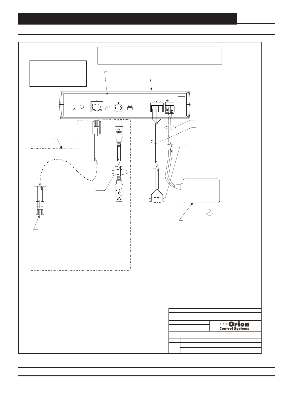
Communication Devices
CommLink 5 Connections & Wiring
WARNING! If You Are Using The IP
Module With Your CommLink, Do Not
Have Your Ethernet Connection And
USB Connection Connected At The
Same Time. This Could Cause
Unreliable Communications.
DIAG
Optional Items
Not Required
For CommLink-Only
Installations.
USB Cable (Included).
Connect This Cable To
Your Computer USB Port
For Direct Connection To
The CommLink 5.
NOTE: A CommLink Is Always Required With A Networked Multiple Loop System.
It Is Used For Alarm Callout, Remote
Connection To The
Notification Or Remote Computer Connection Is Required.
System Is Desired. An IP Module Is Only Required If E-Mail Alarm
When Used With
MiniLink, Switch
Should Be Set To
Computer Connection, or Direct Computer
CommLink 5
Communications Interface
Multiple.
10/100
ETHERNET
ACT LNK
MULTIPLE
LOOP
COMPUTER
USB
SINGLE
BAUD
HIGH
LOW
SHLD
R(+)
485 LOOP
T(-)
GND
POWER
Serial #
24V
Connect To Controller
As Required By Your
Specific System
Wiring Instructions.
24 VAC Power
18 Gauge 2 Conductor
With Shield (Not Included)
See Note 1
Optional - Prefabricated Ft. Long CAT5
10
Ethernet Cable (Included With Optional OE41502 IP Module Kit).
Ethernet Router On Your LAN.
Connect To A 10/100 Base-T
If A Longer
Ethernet Cable Is Required, You Will Need To
Obtain (From Others) And Install An Ethernet
Cable Of The Required Length For Your
Installation.
NOTES:
1) For Direct Connection Via USB, Your Computer Must Have An Unused USB
Port Available. Drivers For Your USB Port Are Provided On A CD Supplied With
The CommLink 5. Please Follow The Directions In The CommLink 5 Technical
Guide To Install And Configure The USB Drivers.
2) The CommLink 5 Cannot Communicate With The Control System Through Its
Ethernet Port And USB Port At The Same Time.
3) All Wiring Must Conform To Applicable Federal, State & Local Electrical Wiring
Codes.
120 to 24 VAC Power Pack
(Included) Connect To 120/1/60
Duplex Receptacle (By Others)
If Desired A 24 VAC Transformer
Included)
Rated At 12 VA Minimum May Be
(Not
Used Instead Of The Supplied Power Pack.
Use 18 Gauge Minimum 2 Conductor Wire
Between The Transformer & CommLink 5
Terminals
JOB NAME
FILENAME
CommLink5-Setup1A.cdr
01/18/13
PAGE
1 of 1
DATE:
Wiring & Connection Diagram
BY:
B. Crews, S. Olson
DESCRIPTION:
OE361-13 CommLink 5
Figure 54: OE361-13 CommLink 5 Computer Connection and Wiring
VCM-X Component & Systems Wiring76
Page 77

Communication Devices
IP-Module General Installation Instructions
Installing the OE415-02 IP Module into the CommLink 5
Round Pin Hole
R
R
GND
GND
SH
24VAC
24VAC
SH
T
T
IP Module
Socket
IP Module Installation Instructions
Location
Pin - Typ.
WiPort NR
LANTRONIX
00-20-4A-89-6B-EE
P5001000-01 Rev
W
Taiwan
Pat. 4972,470 06W
ade in
M
IP Module (Part Of
OE415-02 IP
Module Kit). Used
When TCP/IP LAN
Or Internet
Communications
With The Control
.A11
21
System Is Desired.
IP Module Installation Instructions:
PIC
PIC
32
32
First Remove The Enclosure Screws That Hold
The Top And Bottom Of The CommLink
Enclosure Together. Remove The Top Half Of
The Enclosure To Access The Circuit Board And
IP Module Socket.
Insert The IP Module’s Guide Pins Into The
Round Pin Holes On The CommLink Circuit
Board As Shown. When The Pins Are Properly
Aligned, Press Down On The IP Module Firmly
To Seat It Into Its Socket.
After Making Sure The IP Module Is Firmly
Seated, Replace The CommLink Cover And
Secure The Enclosure Halves Back Together
With The Enclosure Screws That Were
Previously Removed.
Follow The Instructions In This Guide For
Installing The IP Module Software And
Configuring The IP Module For Your Control
System.
JOB NAME
FILENAME
IP-ModInstall1A.CDR
BY:
S. Olson
PAGE
1 of 1
DATE:
01/18/13
DESCRIPTION:
CommLink 5 IP Module Installation
Wiring & Connection Diagram
Figure 55: OE415-02 IP Module Installation Instructions
VCM-X Component & Systems Wiring
77
Page 78

Communication Devices
On-Site Computer Connections & Wiring
S. Olson
BY:
Connect To MiniLink PD Network Terminals
(When Used)
Otherwise Connect to VCM-X E-BUS Controller
Communications Terminal
24 VAC
110 VAC To
Power Pack
(Supplied With CommLink 5)
Serial #
24V
GND
POWER
T(-)
SHLD
R (+)
485 LOOP
LOW
(Front View)
CommLink 5
Optional Computer Connection Diagram
T
SHLD
R
HIGH
USB
COMPUTER
10/100
ETHERNET
SINGLE
MULTIPLE
BAUD
LOOP
ACT LNK
DIAG
(Back View)
CommLink 5
Type B USB
485 LOOP
R
G
T
Typical Terminal Blocks. All Wiring To Be
T To T, SHLD (G) To SHLD (G) & R To R
Note: Set CommLink Internal Switch To “Multi” When
MiniLink PD Is Used Otherwise Switch Must Be Set To
“Single”
Cable End
CommLink 5 Must
Connect Type A Cable
End To USB Port On Desktop Or
Laptop Personal Computer & Type B
The CommLink 5 Can
USB Drivers Supplied With The
End To USB Port On CommLink 5.
Be Installed On Your Computer Before
NOTE:
USB Cable Assembly
(Supplied With CommLink 5)
Be Used
Cable End
Type A USB
JOB NAME
DESCRIPTION:
01/04/13
DATE:
FILENAME
O-VCMX-JS-Comp-Only-1A.cdr
PAGE
Wiring & Connection Diagram
VCM-X Job Site Computer Only
1 of 1
Figure 56: On-Site Computer Connection
Job-Site Laptop Computer
(By Others) with Prism 2 Software Installed
VCM-X Component & Systems Wiring78
Page 79

Communication Devices
Remote Job-Site Computer Connections & Wiring
S. Olson
FILENAME
BY:
DESCRIPTION:
01/04/13
DATE:
Wiring & Connection Diagram
VCM-X IP Module Job Site Computer Connections
24 VAC
110 VAC To
Power Pack
(Supplied With CommLink IV)
Connect To MiniLink PD Network
Terminals (When Used)
Otherwise Connect to VCM-X E-BUS
Controller Communications Terminal
T
SHLD
JOB NAME
R
Serial #
24V
GND
POWER
T(-)
SHLD
R (+)
485 LOOP
LOW
HIGH
BAUD
USB
COMPUTER
SINGLE
MULTIPLE
LOOP
(Back View)
10/100
ETHERNET
ACT LNK
DIAG
CAT5 Ethernet
Cable (By Others)
(Front View)
CommLink 5
w/IP Module Installed
Optional Computer Connection Diagram
Using IP-Module For Job-Site Location Connection
(By Others)
Firewall //Proxy Router/Modem
485 LOOP
O-VCMX-IP-Mod-Computer-1A.CDR
PAGE
1 of 1
R
G
T
Typical Terminal Blocks. All Wiring
To Be T To T, SHLD (G) To SHLD
(G) & R To R
(Supplied With IP Module)
CAT5 Crossover Ethernet Cable
Used For Setting IP Address On CommLink 5.
See IP Module Technical Guide Supplied With IP
CAT5 Ethernet Cable (By Others)
Crossover Cable After Setting IP Address And
Modem (By Others) As Desired Using Standard
Connect CommLink 5 To Firewall, Proxy, Router Or
Module For Software & Installation Details. Remove
CAT5 Ethernet
CAT5 Ethernet
Cable (By Others)
To Next Node On
Building LAN Or WAN
Cable (By Others)
Figure 57: Remote Job-Site Computer Connection
VCM-X Component & Systems Wiring
Personal Computer
(By Others) with Prism 2 Software Installed
79
Page 80

Communication Devices
USB-Link 2 Computer Connections & Wiring
SHLD
T
T
SHLD
R
R
Or Your MiniLink
S. Olson
BY:
Using Prism II.
Adapter
PL101904
Supplied With USB-Link
Mini-DIN Cable
Adapter
PL101905
Supplied With USB-Link
PL101904
This Only Allows Communications With The Board It Is Connected To
Use The Adapter To Plug In To ATerminal Socket And Connect
NOTE: .
The USB-Link On Boards That Don’t Have A Female Mini-DIN Plug Connection.
Mini-DIN Cable
All Controllers
. See Note 1.
P 101905L
This Allows Communications With
That Are Connected To The System
NOTE:
Use The Adapter And Wire To A Terminal Block
To Connect The USB-Link To The Local Communications Loop
On Boards That Don’t Have A Female Mini-DIN Plug Connection.
Line Voltage
24 VAC
(8 VA)
WARNING
OBSERVE
POLARITY
, You Will NeedAn EPROM Upgrade Before You Can
. Set The USB-Link Communication Switch To Stand Alone, Set The Type Of CommLink In
Notes:
1. For Networked Systems, In The Event That You Have A CommLink II or CommLink III
And Have An EPROM Software Version Earlier Than 3.15 Installed In The CommLink,
View All Controllers On Your System. Contact WattMaster Technical Support For An EPROM Update.
If You HaveA CommLink IV This WIll Not Be A Problem.
Even Without The EPROM Upgrade You Can Still View A Single Controller
To Do This You Must First Disconnect The Communication Loop From The Controller Your USB-Link Is
Has An EPROM Software Version Earlier Than 3.14
Plugged Into
JOB NAME
FILENAME
Prism II To USB Link Stand Alone, And Cycle Power By Disconnecting And Reconnecting the USB Power
Supply Cable.
DESCRIPTION:
01/04/13
VCM-X Job Site USB-Link 2
Wiring & Connection Diagram
DATE:
O-VCMX-JS-USBLINK2-1A.CDR
Personal Computer.
USB Drivers Supplied With The USB-
Connect Type A Cable End To
USB Port On Desktop Or Laptop
NOTE:
1 of 1
PAGE
Before USB-Link 2 Can Be Used.
Link 2 Must Be Installed On Your Computer
Optional USB-Link 2 Connection Diagram
Mini-DIN Plug
Controller With
VCM-X Unit Controller
All
This Allows
NOTE:
That Are Supplied
Controllers That Are
Communications With
With Them.
- IN Connector On Controllers
Mini D Plug
Link
Mini-DIN Cable
Supplied With USB-
- IN Female
Connect The USB-Link
Mini D Cable To The
Figure 58: Computer Connections Using USB-Link 2
Installed
Software
Computer
(By Others)
With Prism II
.
See Note 1.
Connected To The System
Mini-DIN Port On USB-Link.
Connect Mini-DIN Cable End To
VCM-X Component & Systems Wiring80
Baud Rate.
Communication Speed Switch
USB-Link 2
Depending on Your Controller’s
Must Be Set To Low or High Speed
Your Installation.
Communication Switch
Or Network Depending On
Must Be Set To Stand Alone
STANDALONE
NETWORK
USB Port On USB Link.
Connect Type B Cable End To
USB Cable
Supplied With
USB-Link
Page 81

Communication Devices
MiniLink Polling Device Wiring Using Modular Connectors
ADD
B. Crews
2
1
ADD
This Switch Should Be
In The OFF Position
As Shown
CX7
U1
MiniLink Polling Device - Wiring Using Power/Comm Cables
U7
4
CX1
P1
RV1
8
16
C1
R3
C4
32
C2
X1
YS101818P552
PROCESSORPBOARD
C1
CX5
CX4
U4
CX3
U3
CX2
VREF
ADD
X1
U5
R4
Set For Address 13
Address Switch Shown Is
JOB NAME
DRAWN BY:
DESCRIPTION:
Component Wiring Diagram
OE364-22 MiniLink Polling Device
02/03/04
Controller
Address Switch
The Address For Each MiniLink PD
Must Be Unique To The Other MiniLink PDs
On The Network Loop And Be Between 1 and 60
Note:
The Power To The MiniLink PD Must Be Removed And
Reconnected After Changing The Address Switch
Settings In Order For Any Changes To Take Effect.
Disconnect All Communication Loop Wiring From The
MiniLink PD Before Removing Power From The MiniLink
PD. Reconnect Power And Then Reconnect
Caution
Set For Address 1
Communication Loop Wiring.
1.) All Wiring To Be In Accordance With Local And National Electrical
Codes And Specifications.
Notes:
2.) All Modular Power/Comm Cables Are To Be WattMaster Part
Number PCC-XX Or PCCE-XX Cables.
3) Connection To The Power/Comm Board And/Or Other MiniLink PDs Can Be
Made By Using The Local Loop Modular Connector As Shown On Page 1 Or
By Using 2 Conductor With Shield Communication Wires As Shown On
Page 2. Connections To The HVAC Unit Controller Must Be Made By Using
2 Conductor With Shield Communication Wires Only.
Address Switch Shown Is
C3
U11
YS101900PMINILINK
POLLING
DEVICE
CX6
REV.1
RN2
U6
U10
D1
U6
CX6
U1
PHILIPS
CX1
C3
1
R1
U2
RAM
EPROM
LED 1
LED 2
POWER
R2
CX2
WDOG
C10
R30X2R29
R28
C9
RN3
P3
R24
LD4
U14
NETWORK
DRIVER
CX14
U13
LOOP
DRIVER
CX13
U15
PROC.
DRIVER
CX15
LD6
0-10V
THERM
4-20mA
AIN2
C8
AIN1
0-10V
THERM
4-20mA
R27
C7
U12
R25
R26
V1
32
16
8
4
2
1
R
T
NETWORK
LOOP
LD5
R
SHLD
T
LOCAL LOOP
P4
GND
AIN 2
AIN 1
OFF=0-5V
+5V
GND
24VAC
D4
R31
P5
SHLD
C11
OFF
ADD
TB2
D5
TB1
TB4
TB3
SW1
Not Used
Communication
Wiring To Be Wired
24 VAC
Class 2
GND
24VAC
T to T, SHLD (G) to
SHLD (G)&RtoR
Transformer
Rated For
6 VA Load
Minimum
485 LOOP
T
G
R
T
SHLD
R
Line Voltage
FILENAME
O-MiniLinkPolDevWr1A.CDR
Connect To
Connect To
CommLink
Terminals
Only One
HVAC Unit
Controller
Terminals
(See Note 3)
COMM
IN
P2
Power/Comm Board
“IN” Modular
DATE:
PAG E
Connector
On Next
Minilink PD
P3 or P5
P3 or P5
Connector
On Previous
Minilink PD
MiniLink PD
To Be Connected
To CommLink.
Assemblies Should Be Wired Using 18 Ga. Min. 2 Conductor
Connector
(See Note 3)
Note: All Communication Wiring Not Utilizing Modular Cable
1of2
Twisted Pair With Shield Belden #82760 Or Equivalent.
Figure 59: OE364-22 MiniLink Polling Device Wiring Using Modular Connectors
VCM-X Component & Systems Wiring
81
Page 82

Communication Devices
MiniLink Polling Device Wiring Using Wire Terminals
ADD
B. Crews
ADD
This Switch Should Be
CX7
U1
MiniLink Polling Device - Wiring Using Standard Communication Wire Instead Of Power/Comm Cables
2
1
In The OFF Position
As Shown
C1
U7
CX1
C4
P1
RV1
8
4
R3
X1
YS101818P552
PROCESSORPBOARD
CX4
CX3
U3
VREF
32
16
Set For Address 13
Address Switch Shown Is
JOB NAME
DRAWN BY:
DESCRIPTION:
Component Wiring Diagram
OE364-22 MiniLink Polling Device
02/03/04
FILENAME
Controller
Address Switch
ADD
The Address For Each MiniLink PD
Must Be Unique To The Other MiniLink PDs
Note:
The Power To The MiniLink PD Must Be Removed And
Reconnected After Changing The Address Switch
On The Network Loop And Be Between 1 and 60
Settings In Order For Any Changes To Take Effect.
Disconnect All Communication Loop Wiring From The
MiniLink PD Before Removing Power From The MiniLink
Caution
PD. Reconnect Power And Then Reconnect
Communication Loop Wiring.
Set For Address 1
Address Switch Shown Is
C3
X1
U11
YS101900PMINILINK
POLLING
DEVICE
CX6
C2
C1
CX5
U5
U4
CX2
R4
REV.1
RN2
U6
U10
D1
U6
CX6
U1
PHILIPS
CX1
C3
1
R1
U2
RAM
EPROM
LED 1
LED 2
POWER
C10
R30X2R29
R28
C9
RN3
P3
R24
LD4
WDOG
R2
CX2
C8
U14
NETWORK
DRIVER
CX14
U13
LOOP
DRIVER
CX13
U15
PROC.
DRIVER
CX15
0-10V
THERM
4-20mA
AIN2
AIN1
0-10V
THERM
4-20mA
R27
C7
U12
R25
R26
V1
32
16
8
4
2
1
NETWORK
LOOP
LD5
LOCAL LOOP
LD6
P4
OFF=0-5V
D4
R31
P5
R
SHLD
T
R
SHLD
T
GND
AIN 2
AIN 1
+5V
GND
24VAC
OFF
SW1
All Communication
Wiring To Be Wired
ADD
T to T, SHLD (G) to
TB4
TB3
Not Used
TB2
C11
D5
TB1
GND
24VAC
24 VAC
Notes:
SHLD (G)&RtoR
Class 2
1.) All Wiring To Be In Accordance With Local And National Electrical Codes And
Specifications.
Transformer
Rated For
6 VA Load
PCCE-XX Cables.
3) Connection To The Power/Comm Board And/Or Other MiniLink PDs Can Be Made By Using
2.) All Modular Power/Comm Cables Are To Be WattMaster Part Number PCC-XX Or
Minimum
The Local Loop Modular Connector As Shown On Page 1 Or By Using 2 Conductor With
Shield Communication Wires As Shown On Page 2. Connections To The HVAC Unit
485 LOOP
T
G
R
T
SHLD
R
Line Voltage
Controller Must Be Made By Using 2 Conductor With Shield Communication Wires Only.
T
SHLD
R
Connect To
Previous MiniLink
HVAC Unit
Controller
O-MiniLinkPolDevWr1A.CDR
Connect To
PD TB4 Terminal
Or CommLink
Terminals
Terminals
(See Note 3)
T
SHLD
R
Power/Comm Board
“IN” Terminals
(See Note 3)
DATE:
PAG E
TB4 Terminals
On Next
Minilink PD
Only One
MiniLink PD
To Be Connected
Assemblies Should Be Wired Using 18 Ga. Min. 2 Conductor
Note: All Communication Wiring Not Utilizing Modular Cable
2of2
To CommLink.
Twisted Pair With Shield Belden #82760 Or Equivalent.
Figure 60: OE364-22 MiniLink Polling Device Wiring Using Wire Terminals
VCM-X Component & Systems Wiring82
Page 83

Communication Devices
Power/Comm Board Wiring For Local Loops
WARNING!
DO NOT GROUND THE 24V TRANSFORMER
THAT IS TO BE USED WITH THE POWER/COMM
BOARDS. GROUNDING OF THE TRANSFORMER
WILL DAMAGE THE POWER/COMM BOARD
AND ALL BOARDS CONNECTED TO IT. A
SEPARATE TRANSFORMER MUST BE USED
FOR EACH POWER/COMM BOARD. NO
EXCEPTIONS. DO NOT CONNECT ANY OTHER
DEVICES TO THE TRANSFORMER USED FOR
THE POWER/COMM BOARD!
Power/Comm Cable Power/Comm Board,
System Manager, Or Modular VAV/Zone Controller On Local Loop
If This Is The First Power/Comm Board On The Local Loop,
No Connection Is Required. See Note 2.
From Other
Connect To Modular VAV/Zone Controller
If This Is First Power/Comm Board
On Local Loop - Otherwise No
Connection Is Required. See Note 2.
Line Voltage
24VAC Transformer (By Others)
See System Configuration Installation &
Commissioning Section Of This Manual
For Detailed Sizing Information
4 Amp Slow Blow Fuse
CAUTION!
No Can Be
MinLink PDs
Connected To The Same
Power/Comm Board(s) That
Are Used To Supply Power
And Communications For
Modular VAV/Zone
Controllers And System
Manager On The Local Loop.
Note:
Diagram Shown Is For Wiring Of
Power/Comm Board When Used
For Connecting Local Loop Devices
Such As Modular VAV/Zone
Controllers, System Manager(s) and
Other Power/Comm Boards. See
Page 2 Of This Drawing For Wiring
When Power/Comm Board Is Used
For Connection Of MiniLink Polling
Devices On The Network Loop.
24VAC
Local Loop RS-485
9600 Baud
OUT
COMMP IN
P2
YS101856
REV. 0
POWER & COMM
SHLD
R
POWER & COMM
DIST. BOARD
P4
TB1
C1
T
P5
Local Loop RS-485
TB2
VAC
24
25
F1
4A
LD1
POWER
V1
R1
D1
P1
P3
All Comm Loop Wiring Is
T
SH
R
9600 Baud
Straight Thru
T
T
SH
SH
R
R
T
SH
R
Power/Comm Cable To Power/Comm
System Manager, Or Modular VAV/Zone Controllers On Local Loop Only.
Other Board(s),
JOB NAME
Notes:
1.) All wiring to be in accordance with local and national electrical codes
and specifications.
2.) All modular power/comm cables are to be WattMaster part number
PCC-xx or PCCE-xx cables. All other communication wiring to be 2
conductor twisted pair with shield (Belden #82760 or equivalent).
FILENAME
O-Pwr-CommWire1A.CDR
02/11/2004
DATE:
PAGE
1 of 2
OE365-01 Orion Power/Comm Board
DESCRIPTION:
Local Loop Wiring Diagram
Figure 61: OE365-01 Power/Comm Board Wiring When Used For Local Loop Devices
VCM-X Component & Systems Wiring
DRAWN BY:
B. Crews
83
Page 84
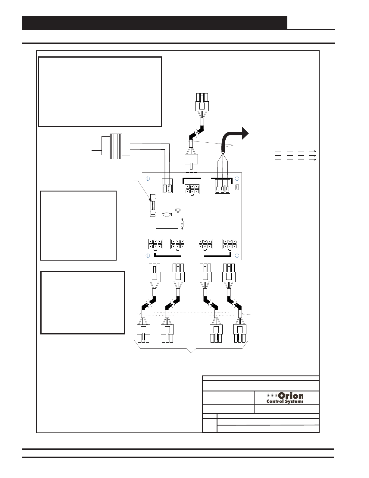
Communication Devices
Power/Comm Board Wiring - When Used For Network Loop Devices
WARNING!
DO NOT GROUND THE 24V TRANSFORMER
THAT IS TO BE USED WITH THE POWER/COMM
BOARDS. GROUNDING OF THE TRANSFORMER
WILL DAMAGE THE POWER/COMM BOARD
AND ALL BOARDS CONNECTED TO IT. A
SEPARATE TRANSFORMER MUST BE USED
FOR EACH POWER/COMM BOARD. NO
EXCEPTIONS. DO NOT CONNECT ANY OTHER
DEVICES TO THE TRANSFORMER USED FOR
THE POWER/COMM BOARD!
Line Voltage
24VAC
24VAC Transformer (By Others)
See System Configuration Installation &
Commissioning Section Of This Manual
For Detailed Sizing Information
4 Amp Slow Blow Fuse
CAUTION!
No Local Loop Devices
(Modular VAV/Zone
Controllers, System
Manager(s) Etc.) Can Be
Connected To The Same
Power/Comm Board(s) That
Are Used To Supply Power
And Communications For
MinLink PDs On The
Network Loop.
25
F1
OUT
From Other
COMMP IN
P2
YS101856
REV. 0
POWER & COMM
SHLD
R
POWER & COMM
DIST. BOARD
P4
Use To Connect CommLink When
This Is the First Power/Comm Board
On The Network Loop. Otherwise No
Connection Is Required. See Note 2.
Network Loop RS-485
192000 Baud
TB1
C1
T
P5
Comm/Power Cable Power/Comm
Board Used For Connecting MiniLink PDs Or Previous MiniLink
PD On Network Loop. If This Is The First Power/Comm Board
On The Network Loop, This Power/Comm Cable Connection Is
Not Required. Instead Use The 3 Pole Terminal Block
Communication Connection As Shown Below And Connect
To The CommLink. See Note 2.
TB2
VAC
24
LD1
4A
P1
POWER
V1
R1
D1
P3
All Comm Loop Wiring Is
Straight Thru
T
T
SH
R
T
SH
SH
R
R
T
SH
R
Note:
Diagram Shown Is For Wiring
When
Power/Comm Board Is Used For
Connection Of MiniLink Polling
Devices On The Network Loop.
For Wiring Of Local Loop Devices
Such As Modular VAV/Zone
Controllers, System Manager(s) and
Other Power/Comm Boards On The
Local Loop See Page 1 Of This
Network Loop RS-485
19200 Baud
Drawing For Wiring .
Connect Power/Comm Cables To Power/Comm
Or MiniLink PDs On The Network Loop Only.
Notes:
1.) All wiring to be in accordance with local and national electrical codes
and specifications.
2.) All modular power/comm cables are to be WattMaster part number
PCC-xx or PCCE-xx cables. All other communication wiring to be 2
conductor twisted pair with shield (Belden #82760 or equivalent).
Other Distribution Board
JOB NAME
FILENAME
O-Pwr-CommWire1A.CDR
DATE:
02/11/2004
PAG E
2 of 2
OE365-01 Orion Power/Comm Board
DESCRIPTION:
Network Wiring Diagram
DRAWN BY:
Figure 62: OE365-01 Power/Comm Board Wiring When Used For Network Loop Devices
B. Crews
VCM-X Component & Systems Wiring84
Page 85

Add-On Devices
Add-On Devices Diagrams
VCM-X Component & Systems Wiring
85
Page 86

Add-On Devices
EPROM
RAM
PAL
PIN 1
PIN 1
CPU
Lighting Panel Wiring For Standard Lighting Contactors
Required VA For Transformer
Caution: If Lighting Contactor Coil Current
Draw Is More Than 2 Amps And/Or Does
Not Use A 24VAC Coil, A Pilot Duty Relay
That Has A Current Draw Of Less Than 2
Amps @ 24VAC Must Be Used To Energize
The Lighting Contactor. ASeparate
Transformer Rated For The Total Lighting
Contactor(s)Or Pilot Relay Current Draw
Must Always Be Used To Power The Circuit.
GND
24V
Lighting Contactors Or
Pilot Duty Relays
(By Others)
Light Circuit 1
Light Circuit 2
Light Circuit 3
Light Circuit 4
Light Circuit 5
Light Circuit 6
Light Circuit 7
Note:
All Circuit Board Contacts Are N.O.
!
All Contacts Are Rated For 2 Amps @
!
24VAC Pilot Duty Only
Do Not Apply Any Voltage Greater Than
!
24VAC
All Lighting Contactors
Must Be Wired For N.C.
Operation So That System
Fails To Lights On Mode.
The Address For Each Controller
Must Be Unique To The Other Controllers
Line Voltage
This Switch Must Be
In The ON Position
As Shown
On The Local Loop
C1
C2
C3
C4
C5
C6
C7
Each Controller = 25VA Max.
See Note 1
Line Voltage
24VAC
GND
K1
K2
K3
K4
K5
K6
K7
Lighting Panel Controller
These Switches Should Be
In The OFF Position
As Shown
ADD
OE310-21-LP
Light Sensor (Optional)
GND
+5V
SIG
ANALOG
INPUTS
+V
+V
1
2
3
4
5
6
7
8
G
G
ANALOG
OUTPUTS
A1
A2
G
T
SH
R
Note:
Set-up, Programming And Monitoring Of The Lighting
Panel Controller Requires The Use Of A Personal
Computer And Prism Software.
Momentary Pushbuttons
T
SH
R
(Optional)
Communications To Other
Controllers On The Local
Override Circuit #1
Override Circuit #2
Override Circuit #3
Override Circuit #4
Override Circuit #5
Override Circuit #6
Override Circuit #7
Local Loop RS-485
Loop
16
4
8
1
ADD
Address Switch Shown Is
Set For Address 1
Caution!
Controller Must Have Address Switch Set Between 1 And 60
1.)24 VAC Must Be Connected So
That All Ground Wires Remain
Common.
2.)All Wiring To Be In Accordance With
Local And National Electrical Codes
and Specifications.
Controller
Address Switch
3.)All Communication Wiring To Be 18
Ga. Minimum, 2 Conductor Twisted
Pair With Shield. Belden #82760 Or
Equivalent.
4.)It Is Recommended That All
Controllers Address Switches Are
Set Before Installation.
2
Address Switch Shown Is
Set For Address 13
Figure 63: OE310-21-LP Lighting Panel Controller Wiring
86
ADD
JOB NAME
FILENAME
W-LightingPnlStd1.CDR
DATE:
05/12/04
PAGE
OE310-21-LP Lighting Panel Controller Wiring
1
Using Standard Lighting Relays
CONTROLS
DRAWN BY:
DESCRIPTION:
B. Crews
VCM-X Component & Systems Wiring
Page 87

Add-On Devices
GPC-X Controller Wiring
Figure 64: OE332-23-GPCX GPC-X Controller Wiring
VCM-X Component & Systems Wiring
87
Page 88

Add-On Devices
GPC-X Controller - Address Switch Setting
Figure 65: OE332-23-GPCX GPC-X Controller Addressing
88
VCM-X Component & Systems Wiring
Page 89
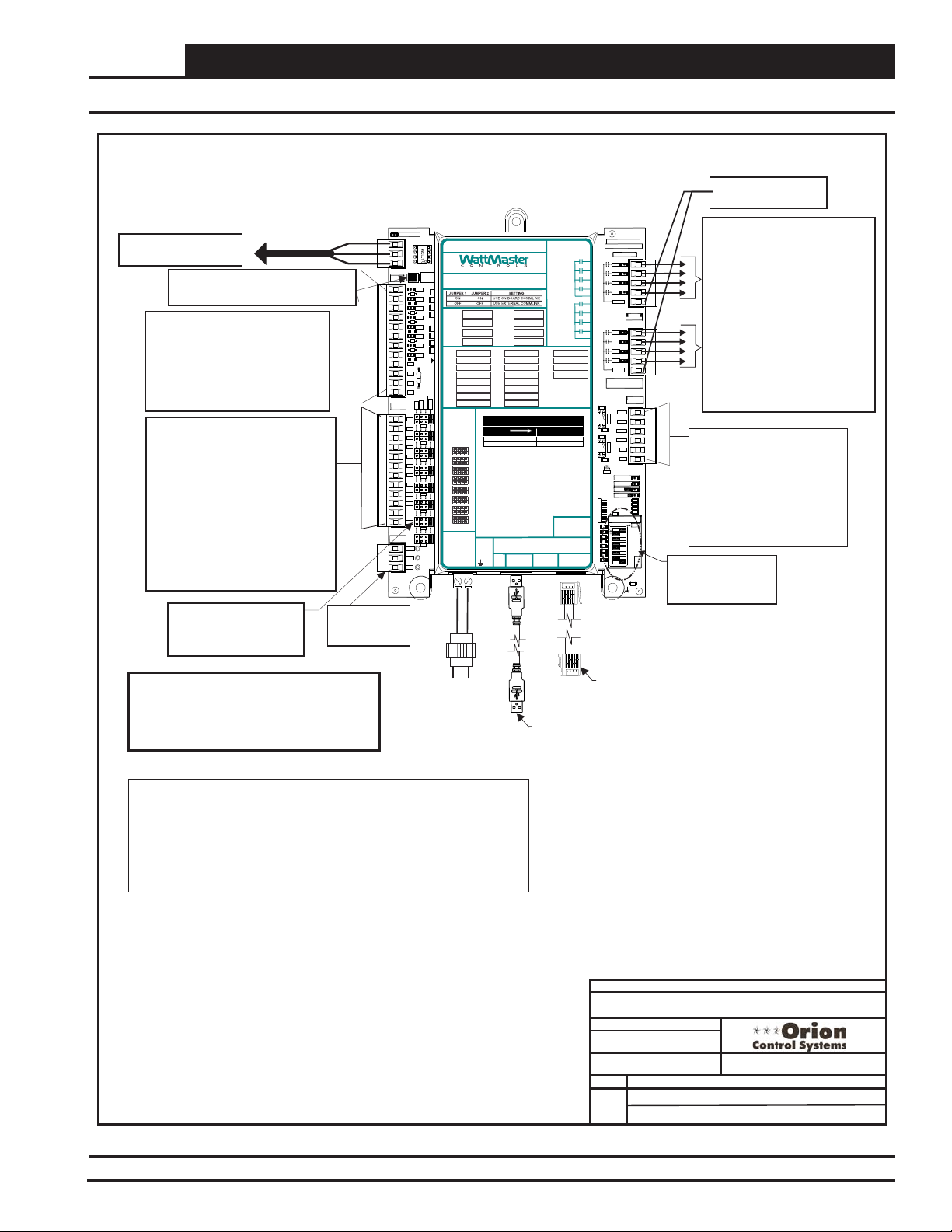
Add-On Devices
GPC-XP Controller Wiring
All Communication Loop Wiring Is
Straight Through
T To T, R To R, SHLD To SHLD
Local Loop RS-485
Connect To Next Device
On The Local Loop
CommLink Jumpers
Both On = Use On Board CommLink
Both Off - Use External CommLink
Binary Inputs BIN1Through BIN8
Configured for The Following:
1. Not Used
2. Normally Closed Operation
3. Normally Open Operation
4. Read Global Binary
5. Push-Button Override
6. Follow Relay
Analog Inputs AI1Through AI8
Configured For the Following:
1. Thermistor 10K Ohm Type III
Temperature Sensors (Fahrenheit)
2. Thermistor 10K Ohm Type III
Temperature Sensors (Celsius)
3. 4 - 20mA User Scaled
4. 0 - 5 vdc User Scaled
5. Wall Sensor Slide Offset
6. Read Global Analog Broadcast from
another Controller
7. Communicating Temperature Sensor
8. Communicating Humidity Sensor
9. Communicating Carbon Dioxide
Jumpers - Typical
Jumpers Must Be Set
Correctly For The Type Of
Input You Require.
9600 Baud
BINARY
INPUTS
ANALOG
INPUTS
VDC
OUTPUTS
5 VDC & 24VDC
Power For
Sensors
LOOPCOMM
TB1
TB3
TB7
TB8
T-
SH
R+
COM
COM
COM
COM
AI1
AI2
AI3
AI4
AI5
AI6
AI7
AI8
GND
GND
GND
GND
+24V
+5V
GND
RS-485 COMMUNICATION LOOP. WIRE
“R” TO“R”, “T” TO “T” “SHLD” TO “SHLD”
ON BOA
COMMLI
CONNEC
R38
BIN1
300
D6
R41
BIN2
300
D7
R43
300
BIN3
R47
D8
300
RLY1 =
BIN4
D9
RLY2 =
BIN5
300
D10
RLY3 =
300
BIN6
D11
RLY4 =
300
BIN7
R61R59R55R51
D12
300
AI1 =
BIN8
D13
AI2 = BI2 = AO2 =
CUTTO ISOLATE
COMFROM GND
AI3 = BI3 = AO3 =
AI4 = BI4 = AO4 =
AI5 = BI5 =
AI6 = BI6 =
4-20mA
AI7 = BI7 =
THERM
0-10v
0-5v
AI8 = BI8 =
ANALOG
INPUT
AI1
JUMPERS
AI2
0-10V
0-5V
AI1
AI3
AI2
AI3
AI4
AI4
AI5
AI5
AI6
AI7
AI6
AI8
AI7
VDC
OUTPUTS
AI8
+ 24VDC
+ 5VDC
GND
24 VAC
OE338-23-GPC-XP
GPC-XP Controller
RELAYCONTACT
RATING IS 1AMP
MAX @ 24 VAC
LED BLINK COD ES
USB
E-BUS
PORT
PORT
RELAY1
RELAY2
RELAY3
RELAY4
COMMON
RELAY5
RELAY6
RELAY7
RELAY8
COMMON
WattMaster Label
www.wattmaster.com
OE338-23-GPC-XP
GPC-XP CONTROLLER
RLY5 =
RLY6 =
RLY7 =
RLY8 =
BI1 = AO1 =
LED NAME STATUS1 STATUS2
NORMAL OPERAT ION 0 1
SCHEDULE OVERRIDE 0 2
4-20mA
THERM
NOTES:
1.)ANALOG INPUT JUMPER SETTINGS MUST BE
SET FORYOUR SPECIFIC INPUT DEVICE
REQUIREMENT.
2.) IT IS RECOMMENDEDTHAT YOU WRITE THE
DESCRIPTION OF THE INPUT,AND/OR
OUTPUTS YOUARE CONNECTING TO THE
CONTROLLER IN THE BOXES PROVIDEDABOVE
USINGA PERMANENT MARKER (SHARPIE) FOR
FUTURE REFERENCE.
24 VAC POWER ONLY
WARNING!POLARITY MUST BE OBSERVED
OR THE CONTROLLER WILL BE DAMAGED
GND
+24VAC
GND
®
#LB102095
Rev.: 1C
YS102432 REV 3
WATTMASTER CONTROLS
RLY1
RLY2
RLY3
RLY4
RLY1
RLY2
RLY3
RLY4
SERIAL #
1002
R74
U17
AOUT1-2
.1uF
C36
1002
R97
U19
AOUT3-4
.1uF
C46
GND
ADDRESS
1002
1002
1002
1002
1002
1002
1002
1002
SW1
MADE IN USA
COMMON
COMMON
STATUS1
STATUS2
EBUS
POWER
.1uF
24VAC Power
For Relay Outputs
8 Relay Outputs Are Available For
On/Off Control Of Equipment
Configured For the Following:
1. Not Configured
2. On Above / Off Below
3. On Above / On Below
TB2
RELAY
OUTPUTS
TB4
ANALOG
OUTPUTS
AOUT1
AOUT2
AOUT3
AOUT4
GND
GND
TB6
1002
R21
1002
R109
1002
R16
1002
R14
C21
ADD
1
2
4
8
16
32
LOOP
BAUD
1
2
C14
.01uF
4. Off Above / On Below
5. Off Above / Off Below
6. Follow Active Binary Input
7. Follow Inactive Binary Input
8. Follow Relay Output
9. Follow Schedule
10. Ventilation Control
11. Lead Relay for Lead/Lag Control
12. Lag Relay for Lead/Lag Control
Analog Outputs AOUT1 through
AOUT4 Provide (4) 0-10 VDC
Outputs Configured For The
Following:
1. Not Configured
2. Direct Acting Floating Point
3. Reverse Acting Floating Point
4. Direct Acting PID
5. Reverse Acting PID
ADDRESS Dipswitch
is Used for Setting
the Address and
Baud Rate.
Warning:
24 VAC Must Be Connected So That All
Ground Wires Remain Common. Failure To
Do So Will Result In Damage To The
Controller
NOTES:
1.)24 VAC Must Be Connected So
That All Ground Wires Remain
Common.
2.)All Wiring To Be In Accordance With
Local And National Electrical Codes
and Specifications.
3.)All Communication Wiring To Be 18
Ga. Minimum, 2 Conductor Twisted
Pair With Shield. Belden #82760 Or
Equivalent.
4.)It Is Recommended That The
Address Switch Is Set Before
Installation.
Line Voltage
Transformer
Minimum
24 VAC
8 VA
EBC E-BUS Cable
Connect to
Communicating Sensor
USB Cable
Connect to Computer with
Prism II Software Installed For
Stand-Alone Programming
GPCXP-CNTRLWire-1A.CDR
DATE:
PAGE
1 of 1
JOB NAME
FILENAME
12/27/12
DRAWN BY:
DESCRIPTION:
OE332-23-GPC-XP
GPC-XP Controller Wiring
S. Olson
Figure 66: OE332-23-GPCXP GPC-XP Controller Wiring
VCM-X Component & Systems Wiring
89
Page 90

Add-On Devices
GPC-XP Controller Addressing & Baud Rate Selection
Caution:
Disconnect All Communication Loop Wiring From The
Controller Before Removing Power From The Controller.
Reconnect Power And Then Reconnect Communication
Loop Wiring.
Note:
The Power To The Controller Must Be Removed And
Reconnected After Changing The Address Switch
Settings In Order For Any Changes To Take Effect.
OE338-23-GPC-XP
BINARY
INPUTS
ANALOG
INPUTS
VDC
OUTPUTS
LOOPCOMM
TB1
TB3
TB7
+24V
TB8
T-
SH
R+
ON BOA
COMMLI
CONNEC
R38
BIN1
300
D6
R41
BIN2
300
D7
R43
300
BIN3
R47
D8
300
RLY1 =
BIN4
D9
RLY2 =
BIN5
300
D10
RLY3 =
300
BIN6
D11
300
RLY4 =
BIN7
R61R59R55R51
D12
300
AI1 =
BIN8
D13
AI2 = BI2 = AO2 =
COM
CUTTO ISOLATE
COMFROM GND
AI3 = BI3 = AO3 =
COM
AI4 = BI4 = AO4 =
COM
AI5 = BI5 =
AI6 = BI6 =
COM
4-20mA
AI7 = BI7 =
THERM
0-10v
0-5v
AI8 = BI8 =
AI1
ANALOG
INPUT
AI1
AI2
JUMPERS
AI3
AI2
AI4
AI1
AI5
AI3
AI2
AI6
AI3
AI7
AI4
AI4
AI8
AI5
GND
AI5
AI6
GND
AI7
AI6
GND
AI8
GND
AI7
VDC
OUTPUTS
AI8
+ 24VDC
+ 5VDC
GND
+5V
GND
GPC-XP Controller
RS-485 COMMUNICATION LOOP. WIRE
“R” TO“R”, “T” TO “T” “SHLD” TO “SHLD”
www.wattmaster.com
OE338-23-GPC-XP
GPC-XP CONTROLLER
RLY5 =
RLY6 =
RLY7 =
RLY8 =
BI1 = AO1 =
LED BLINK CODE S
LEDNAME STATUS1 STATUS2
NORMAL OPERATI ON 0 1
SCHEDULE OVERRIDE 0 2
4-20mA
0-10V
0-5V
THERM
NOTES:
1.)ANALOG INPUT JUMPER SETTINGS MUST BE
SET FORYOUR SPECIFIC INPUT DEVICE
REQUIREMENT.
2.) ITIS RECOMMENDED THAT YOU WRITE THE
DESCRIPTION OFTHE INPUT, AND/OR
OUTPUTSYOU ARE CONNECTING TO THE
CONTROLLER INTHE BOXES PROVIDED ABOVE
USINGA PERMANENT MARKER (SHARPIE) FOR
FUTURE REFERENCE.
24 VAC POWER ONLY
WARNING!POLARITY MUST BE OBSERVED
OR THE CONTROLLER WILLBE DAMAGED
GND
USB
E-BUS
PORT
PORT
+24VAC
RELAYCONTACT
RATING IS 1AMP
MAX @ 24 VAC
RELAY1
RELAY2
RELAY3
RELAY4
COMMON
RELAY5
RELAY6
RELAY7
RELAY8
COMMON
®
WattMaster Label
#LB102095
Rev.: 1C
YS102432 REV 3
WATTMASTER CONTROLS
RLY1
RLY2
RLY3
RLY4
RLY1
RLY2
RLY3
RLY4
SERIAL #
1002
R74
U17
AOUT1-2
.1uF
C36
1002
R97
U19
AOUT3-4
.1uF
C46
GND
ADDRESS
1002
1002
1002
1002
1002
1002
1002
1002
SW1
MADE IN USA
COMMON
COMMON
STATUS1
STATUS2
EBUS
POWER
.1uF
Baud
9600
57600
TB2
RELAY
OUTPUTS
TB4
ANALOG
OUTPUTS
AOUT1
AOUT2
AOUT3
AOUT4
GND
GND
TB6
1002
R21
1002
R109
1002
R16
1002
R14
C21
ADD
1
2
4
8
16
32
LOOP
BAUD
1
2
C14
.01uF
Address 1 @ 9600 Baud
Address Switch Shown Is
Set For Address 1
BAUD RATE SELECTION
Switch 7 Switch 8
OFF
OFF
OFF
ON
Communication Setting
CommLink IV
CommLink 5 & Stand Alone
Address 5 @ 57,600 Baud
ADD
1
2
4
8
16
32
Baud 0
Baud 1
ADD
ADD
Controller
Address Switch
The Address For Each Controller
Must Be Unique To The Other Controllers
On The Local Loop And Be Between 1 and 59
Address Switch Shown Is
Set For Address 13
1
2
4
8
16
32
Baud 0
Baud 1
ADD
FILENAME
GPCXP-AddressSwitchSet-1A.CDR
12/27/12
DATE:
PAGE
1 of 1
GPC-XP Controller Address & Baud Rate
Figure 67: OE332-23-GPCXP GPC-XP Controller Addressing & Baud Rate Selection
90
VCM-X Component & Systems Wiring
JOB NAME
DRAWN BY:
DESCRIPTION:
OE332-23-GPC-XP
S. Olson
Page 91

Add-On Devices
GPC-XP Controller On-Board CommLink Setting
Caution:
Disconnect All Communication Loop Wiring From The
Controller Before Removing Power From The Controller.
Reconnect Power And Then Reconnect Communication
Loop Wiring.
Note:
The Power To The Controller Must Be Removed And
Reconnected After Changing The Address Switch
Settings In Order For Any Changes To Take Effect.
ON-BOARD COMMLINK SETTING
Jumper 1
ON
OFF
Jumper 2
ON
OFF
Use On-Board CommLink
Use External CommLink
Both Jumpers ON
ON BOARD
COMMLINK
CONNECT
Both Jumpers OFF
ON BOARD
COMMLINK
CONNECT
Setting
BINARY
INPUTS
ANALOG
INPUTS
VDC
OUTPUTS
LOOPCOMM
TB1
TB3
TB7
+24V
TB8
T-
SH
R+
COM
COM
COM
COM
AI1
AI2
AI3
AI4
AI5
AI6
AI7
AI8
GND
GND
GND
GND
+5V
GND
RS-485 COMMUNICATION LOOP. WIRE
“R” TO“R”, “T” TO “T” “SHLD” TO “SHLD”
ON BOA
COMMLI
CONNEC
R38
BIN1
300
D6
R41
BIN2
300
D7
R43
300
BIN3
R47
D8
300
BIN4
RLY1 =
D9
BIN5
300
RLY2 =
D10
300
BIN6
RLY3 =
D11
300
BIN7
RLY4 =
R61R59R55R51
D12
300
BIN8
AI1 =
D13
AI2 = BI2 = AO2 =
CUTTO ISOLATE
COMFROM GND
AI3 = BI3 = AO3 =
AI4 = BI4 = AO4 =
AI5 = BI5 =
AI6 = BI6 =
4-20mA
THERM
0-10v
AI7 = BI7 =
0-5v
AI8 = BI8 =
ANALOG
AI1
INPUT
JUMPERS
AI2
0-5V
AI1
AI3
AI2
AI3
AI4
AI4
AI5
AI5
AI6
AI6
AI7
AI8
AI7
VDC
OUTPUTS
AI8
+ 24VDC
+ 5VDC
GND
OE338-23-GPC-XP
GPC-XP Controller
RELAYCONTACT
RATING IS 1AMP
LED BLINK CO DES
USB
E-BUS
PORT
PORT
MAX @ 24 VAC
COMMON
COMMON
www.wattmaster.com
OE338-23-GPC-XP
GPC-XP CONTROLLER
RLY5 =
RLY6 =
RLY7 =
RLY8 =
BI1 = AO1 =
LED NAME STATUS1 STATUS2
NORMAL OP ERATION 0 1
SCHEDULE OVERRIDE 0 2
4-20mA
0-10V
THERM
NOTES:
1.)ANALOG INPUT JUMPER SETTINGS MUST BE
SET FORYOUR SPECIFIC INPUT DEVICE
REQUIREMENT.
2.) IT IS RECOMMENDEDTHAT YOU WRITE THE
DESCRIPTION OF THE INPUT,AND/OR
OUTPUTS YOUARE CONNECTING TO THE
CONTROLLER IN THE BOXES PROVIDEDABOVE
USINGA PERMANENT MARKER (SHARPIE) FOR
FUTURE REFERENCE.
24 VAC POWER ONLY
WARNING!POLARITY MUST BE OBSERVED
OR THE CONTROLLER WILL BE DAMAGED
GND
+24VAC
RELAY1
RELAY2
RELAY3
RELAY4
RELAY5
RELAY6
RELAY7
RELAY8
WattMaster Label
®
#LB102095
Rev.: 1C
YS102432 REV 3
WATTMASTER CONTROLS
SERIAL #
1002
R74
U17
AOUT1-2
.1uF
C36
R97
1002
U19
AOUT3-4
.1uF
C46
GND
ADDRESS
1002
1002
1002
1002
1002
1002
1002
1002
SW1
MADE IN USA
RLY1
RLY2
RLY3
RLY4
COMMON
RLY1
RLY2
RLY3
RLY4
COMMON
AOUT3
AOUT4
STATUS1
STATUS2
EBUS
POWER
.1uF
TB2
RELAY
OUTPUTS
TB4
ANALOG
OUTPUTS
AOUT1
AOUT2
GND
GND
TB6
1002
R21
1002
R109
1002
R16
1002
R14
C21
ADD
1
2
4
8
16
32
LOOP
BAUD
1
2
C14
.01uF
GPCXP-CommLinkSwitchSet-1A.CDR
DATE:
PAGE
1 of 1
Figure 68: OE332-23-GPCXP GPC-XP Controller On-Board CommLink Setting
VCM-X Component & Systems Wiring
JOB NAME
FILENAME
12/27/12
DRAWN BY:
S. Olson
DESCRIPTION:
OE332-23-GPC-XP
GPC-XP CommLink Setting
91
Page 92
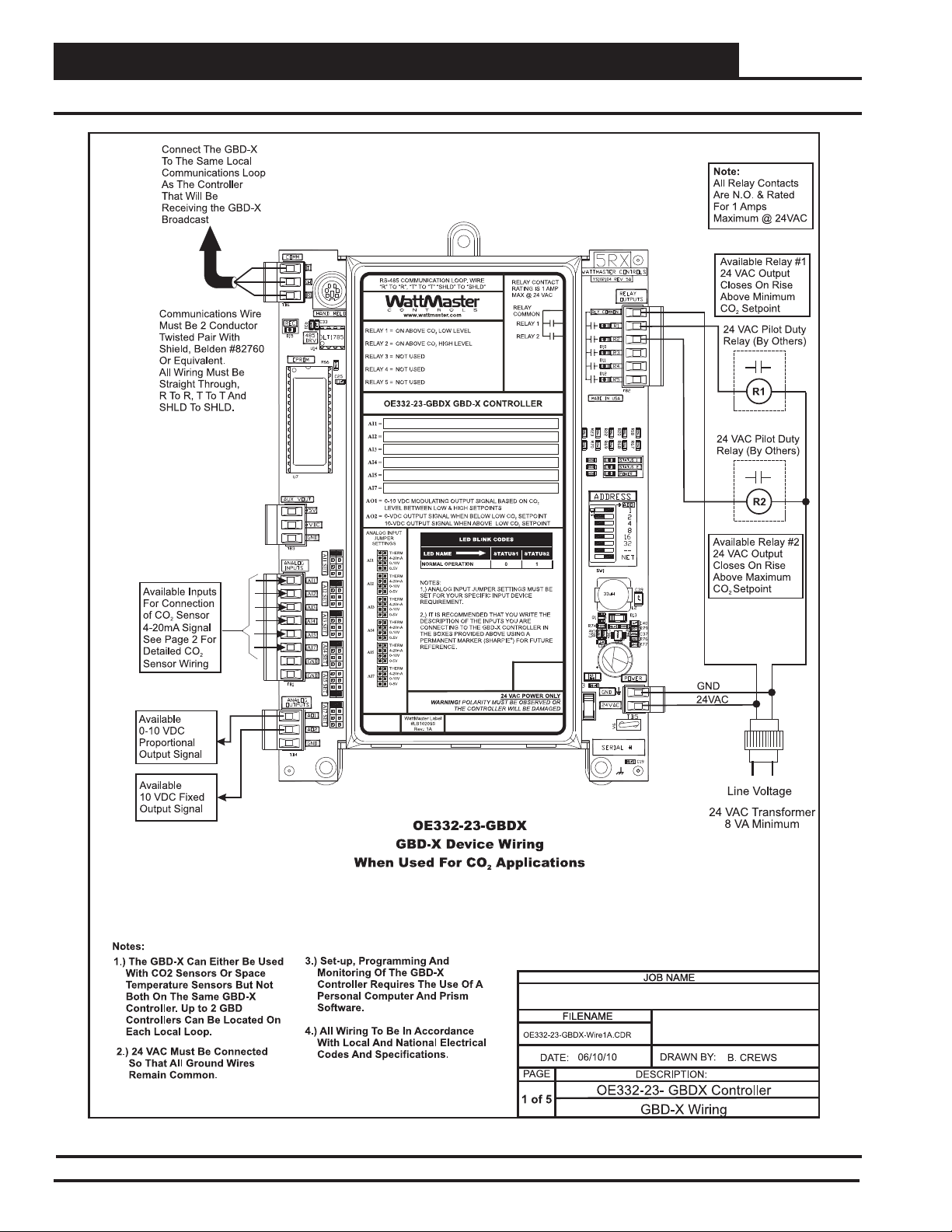
Add-On Devices
GBD-X Controller - CO2 Applications Wiring
Figure 69: OE332-23-GBDX GBD-X Controller Wiring CO2 Applications
92
VCM-X Component & Systems Wiring
Page 93

Add-On Devices
GBD-X Controller - CO2 Applications Wiring (Cont’d)
Figure 70: OE332-23-GBDX GBD-X Controller Wiring CO2 Applications
VCM-X Component & Systems Wiring
93
Page 94

Add-On Devices
GBD-X Controller - Space Temp. Sensor Averaging Wiring
Figure 71: OE332-23-GBDX GBD-X Controller Wiring- Space Temperature Sensor Averaging
94
VCM-X Component & Systems Wiring
Page 95

Add-On Devices
GBD-X Controller - Space Temp. Sensor Averaging Wiring (Cont’d)
Figure 72: OE332-23-GBDX GBD-X Controller Wiring- Space Temperature Sensor Averaging
VCM-X Component & Systems Wiring
95
Page 96

Add-On Devices
GBD-X Controller Address Switch Setting
Figure 73: OE332-23-GBDX GBD-X Controller Addressing
96
VCM-X Component & Systems Wiring
Page 97

Module Wiring & Connections
Module Wiring
& Connections
VCM-X Component & Systems Wiring
97
Page 98

Module Wiring & Connections
HP1C Module Wiring When Used With The VCM-X E-BUS
NOTE:
ALL RELAY OUTPUTS
NORMALLY OPENAND
ARE
RATED FOR 24 VAC POWER
ONLY - 1AMP MAXIMUM LOAD
Head Pressure
Transducers
Set ADDRESS Dip
Switch 1 to ON for
Water Cooled or to OFF
for Air Cooled.
Currently showing OFF
for Air Cooled.
Set ADDRESS Dip
Switch 2 to OFF on all
communicating
applications unless it is
intended to be the
Second Head Pressure
Module on a system. If
set to ON, it will not
communicate. Currently
showing OFF.
+V
RD
WH
GND
BK
RD
WH
GND
BK
RD
WH
BK
GND
RD
WH
BK
GND
SIG
SIG
SIG
SIG
+5V
SIG 1
GND
+V
+5V
SIG 2
GND
+V
+5V
SIG 3
GND
+V
+5V
SIG 4
GND
BIN 1
BIN 2
BIN 3
COM
ADDRESS
PWR
WARNING!! Observe
Polarity! All boards
must be wired with
GND-to-GND and 24
VAC-to-24 VAC.
OE370-23-HP1C
One Condenser
Head Pressure Module
www.aaon.com
MAX @ 24 VAC
RATING IS 1AMP
WattMaster Label
#LB102057-A
Rev.: 1J
RELAYCONTACT
1COrion No.:OE370-23-HP
LED NAME STAT
BLINKSQTY. OF SENSORS INS TALLED
LED NAME
NOPROBLEMS 0
NOSENSORS DETECTED 1
HIGHHEAD PRESSURE DETECTED 2
LOWHEAD PRESSURE DETECTED 3
E-BUS
Connector
One Condenser Head Pressure Module
A1
+5V
HEAD
SIG 1
PRESSURE
GND
TRANSDUCER #1/
A2
+5V
HEAD
SIG 2
PRESSURE
GND
TRANSDUCER #2
A3
+5V
HEAD
SIG 3
PRESSURE
GND
TRANSDUCER #3
A4
+5V
HEAD
SIG 4
PRESSURE
GND
TRANSDUCER #4
COND. ENABLE INPUT
BIN 1
REV. VLV. INPUT ENABLE
BIN 2
BIN 3
NOT USED
COM
COMMON
E-BUS
Connector
COND. ENABLE
REV. VLV. ENABLE
RELAYCOMMON
COND. SIGNAL
COND. FAN
COND. FAN
NOT USED
NOT USED
LED BLINK CODES
NOT USED
NOT USED
NOT USED
AAON No.:
R74860
GND
GND
PWM1PWM1+
PWM2PWM2+
ALARM
GND
R1
R2
R3
R4
RC
AO1
AO2
GND
+24 VAC
R1
R2
R3
R4
Rc
RELAYS
ANALOG
AO1
AO2
GND
PWM1-
PWM1+
PWM2-
PWM2+
ALARM
STAT
COMM
24 VAC
24 VAC Transformer
R1
R2
COMM
YELLOW
BLUE +24 OUT
OPTIONS
Line Voltage
3 VA Minimum
CONDENSER A ENABLE
REVERSING VALVE A ENABLE
HVAC UNIT CONNECTION
Condenser
Signal A
+
COM
Condenser Fan
ECM Motor
Duty Cycle
+24 Volts
OPTIONS Dip Switch Setting
Not Required When
Connected To
VCM-X Modular E-BUS or
VCM-X WSHP E-BUS
Controller
Set ADDRESS Dip
Switch 4 to OFF to
make reversing valve
"ON to Heat / OFF to
Cool” Set to ON to
make reversing valve
“ON to Cool / OFF to
Heat. Currently
showing OFF.
Connect To Other
WattMaster-Approved
E-BUS Expansion
Module(s)
Wiring For One Condenser Head Pressure Module
When Used With Orion VCM-X E-BUS Controller
HSSC Cable
HSSC Cable
Connect To VCM-X E-BUS
Controller or VCM-X WSHP E-BUS
Controller
JOB NAME
FILENAME
HP1C-1A.CDR
DATE:
06/04/15
PAG E
AAON One Condenser Head Pressure Wiring
1
When Used With Orion VCM-X E-BUS Controller
DRAWN BY:
DESCRIPTION:
S. Olson
Figure 74: OE370-23-HP1C One Condenser Head Pressure Module to VCM-X E-BUS Controller Wiring
98
VCM-X Component & Systems Wiring
Page 99

Module Wiring & Connections
HP2C2 Controller Wiring When Used With The VCM-X E-BUS
NOTE:
ALL RELAY OUTPUTS
NORMALLY OPENAND
ARE
RATED FOR 24 VAC POWER
ONLY - 1AMP MAXIMUM LOAD
CONDENSER A ENABLE
REVERSING VALVEA ENABLE
CONDENSER B ENABLE
REVERSING VALVE B ENABLE
Condenser
Signal A
+
COM
Condenser
Signal B
+
COM
Condenser Fan A
YELLOW
BLUE +24 OUT
YELLOW
BLUE +24 OUT
OPTIONS Dip Switch Setting
Not Required When Connected
To VCM-X E-BUS
ECM Motor
+24 Volts
Condenser Fan B
ECM Motor
Duty Cycle
Duty Cycle
+24 Volts
Head Pressure
Transducers
RD
WH
BK
RD
WH
BK
RD
WH
BK
RD
WH
BK
Set ADDRESS Dip Switch 1 to ON for Water
Cooled or to OFF for Air Cooled. Currently
showing OFF for Air Cooled.
Set ADDRESS Dip Switch 2 to OFF on all
communicating applications unless it is
intended to be the Second Head Pressure
Module on a system. If set to ON, it will not
communicate. Currently showing OFF.
Set ADDRESS Dip Switch 3 to ON to
disable Circuit B alarms when only one
Condenser is Used. Currently showing OFF.
Set ADDRESS Dip Switch 4 to OFF to make
reversing valve "ON to Heat / OFF to Cool.”
Set to ON to make reversing valve “ON to
Cool / OFF to Heat.” Currently showing OFF.
SIG
GND
SIG
GND
SIG
GND
SIG
GND
OE370-23-HP2C2
Two Condenser
Head Pressure II Module
AAON No.:
V20660
GND
GND
PWM1PWM1+
PWM2PWM2+
ALARM
GND
R1
R2
R3
R4
RC
AO1
AO2
GND
PWM1-
PWM1+
PWM2-
PWM2+
+24VAC
24 VAC
R1
R1
R2
R2
R3
R3
R4
R4
COMM
Rc
RELAYS
ANALOG
AO1
AO2
GND
OPTIONS
ALARM
STAT
COMM
Line Voltage
24 VAC Transformer
3 VA Minimum
+V
+5V
SIG 1
GND
+V
+5V
SIG 2
GND
+V
+5V
SIG 3
GND
+V
+5V
SIG 4
GND
BIN 1
BIN 2
BIN 3
COM
ADDRESS
PWR
www.aaon.com
Two Condenser Head Pressure II Module
A1
+5V
HEAD
SIG 1
PRESSURE
GND
TRANSDUCER #1
A2
+5V
HEAD
SIG 2
PRESSURE
GND
TRANSDUCER #2
B1
+5V
HEAD
SIG 3
PRESSURE
GND
TRANSDUCER #3
B2
+5V
HEAD
SIG 4
PRESSURE
GND
TRANSDUCER #4
COND.A ENABLE INPUT
BIN 1
REV. VLV. ENABLE INPUT
BIN 2
COND. B ENABLE INPUT
BIN 3
COM
COMMON
WattMaster Label
E-BUS
#LB102110-A
Connector
Rev.: 1A
COND.A ENABLE
REV. VLV. A ENABLE
COND. B ENABLE
REV. VLV. B ENABLE
MAX @ 24 VAC
RATINGIS 1 AMP
RELAYCONTACT
RELAYCOMMON
2C2Orion No.:OE370-23-HP
COND.A SIGNAL
COND. B SIGNAL
COND. FANA
COND. FANA
COND. FAN B
COND. FAN B
LED BLINK CODES
LED NAME STAT
BLINKSQTY. OF SENSORS INSTALLED
LED NAME
NOPROBLEMS 0
NOSENSORS DETECTED 1
HIGHHEAD PRESSURE DETECTED 2
LOWHEAD PRESSURE DETECTED 3
E-BUS
Connector
Connect To Other
WattMaster-Approved
E-BUS Expansion
Module(s)
HSSC Cable
HSSC Cable
Connect To
VCM-X E-BUS
WARNING!! Observe
Polarity! All boards must
be wired with GND-toGND and 24 VAC-to-24
VAC.
Wiring For Two Condenser Head Pressure Module When Used With Orion VCM-X E-BUS Controller
JOB NAME
FILENAME
HP2C2-1A.CDR
DATE:
06/05/15
PAGE
Two Condenser Head Pressure Module Wiring
1
When Used With Orion VCM-X E-BUS Controller
DRAWN BY:
DESCRIPTION:
S. Olson
Figure 75: OE370-23-HP2C2 Two Condenser Head Pressure Module to VCM-X E-BUS Controller Wiring
VCM-X Component & Systems Wiring
99
Page 100

Module Wiring & Connections
Full Digital Module Wiring When Used With The VCM-X E-BUS
OE370-23-FD-A
Full Digital Module
PWR
ADDRESS
+5V
SIG 1
GND
+5V
SIG 2
GND
+5V
SIG 3
GND
+5V
SIG 4
GND
BIN 1
BIN 2
COM
GND
R1
R2
R3
R4
Rc
RELAYS
ANALOG
AO1
AO2
GND
PWM1-
PWM1+
PWM2-
PWM2+
24 VAC
24 VAC Transformer
3 VA Minimum
OPTIONS
WARNING!!
Observe Polarity! All boards
ALARM
must be wired with GND-to-
STAT
COMM
GND and 24 VAC-to-24 VAC.
Failure to observe polarity
could result in damage to the
boards.
Line Voltage
Connect To Other
WattMaster-Approved
E-BUS Expansion
HSSC Cable
HSSC Cable
Module(s)
Wiring For Full Digital Module When Used With Orion VCM-X E-BUS Controller
FILENAME
FullDigital-1A.CDR
DATE:
06/05/15
PAGE
1
When Used With Orion VCM-X E-BUS Controller
Full Digital Module Wiring
Figure 76: OE370-23-FD-A Full Digital Module to VCM-X E-BUS Controller Wiring
100
VCM-X Component & Systems Wiring
Connect To VCM-X
JOB NAME
DRAWN BY:
DESCRIPTION:
E-BUS
S. Olson
 Loading...