

Page 1
www.orioncontrols.com
VCC-X Controller Code: SS1062 Version 2.0 & up
VAV/Zone Controller Code: SS1001, SS1005, SS1025
VCC-X Controller
Operator Interface SD
Technical Guide
Requires Service Tool SD Code: SS1063
Requires System Manager SD Code: SS1068
Page 2
Zone
Zone
IMPORTANT NOTICE
This technical guide provides instructions for using the Modular Service
Tool and Modular System Manager SD with the VCC-X & VAV/Zone
Controllers only. If you are using a different controller, you can download
the applicable SD Technical Guide listed below from our website—
orioncontrols.com. The technical guides can also be printed from the SD
card.
VCB-X Controller - OR-VCBXIOSD-TGD
VCM-X & VCM-X E-BUS Controller - OR-VCMXRNEOISD-TGD
RNE Controller - OR-VCMXRNEOISD-TGD
SA E-BUS Controller - AA-SAOISD-TGD
VCM Controller - OR-VCMOISD-TGD
VAV/CAV and MUA II Controllers - OR-VAVCAVMUAOISD-TGD
SD CARD UPDATING INSTRUCTIONS
The Modular Service Tool and Modular System Manager are equipped with
an SD memory card. This SD card can be removed and easily updated
through a computer by downloading updates, as they become available,
from our website to your computer.
In order to perform any updates, your computer needs an SD card drive or
you will need to purchase an SD card adapter.
Download instructions are found in Appendix B on page 85 of this manual.
www.orioncontrols.com
WattMaster Controls, Inc.
8500 NW River Park Drive · Parkville, MO 64152
Toll Free Phone: 866-918-1100
PH: (816) 505-1100 · FAX: (816) 505-1101
E-mail: mail@wattmaster.com
Visit our website at www.orioncontrols.com
®
AAON
is a registered trademark of AAON, Inc., Tulsa, OK.
WattMaster Controls, Inc. assumes no responsibility for
errors or omissions.
This document is subject to change without notice.
Form: OR-VCCXOISD-TGD-01A
Copyright June 2015 WattMaster Controls, Inc.
Page 3

TABLE OF CONTENTS
OVERVIEW & SYSTEM CONNECTION ...............................................................................4
Modular Service Tool ............................................................................................................................... 4
Modular System Manager SD .................................................................................................................6
MODULAR SERVICE TOOL SD ........................................................................................10
Display Screens and Data Entry Keys ...................................................................................................10
Initialization & Setting the Time & Date ................................................................................................. 11
Setting the Operating Mode & Energy Timer .........................................................................................12
Alarm Search & Override Search ..........................................................................................................13
Schedules & Holidays ............................................................................................................................14
Schedule Override ................................................................................................................................. 15
SYSTEM MANAGER SD ...................................................................................................16
Display Screens and Data Entry Keys ...................................................................................................16
Initialization & Setting the Time & Date .................................................................................................17
Setting the Operating Mode ...................................................................................................................18
Changing Passcodes .............................................................................................................................19
Loop Search and System Alarm Search ................................................................................................20
Unit Alarm Search & Override Search ................................................................................................... 21
Schedules & Holidays ............................................................................................................................22
Schedule Override ................................................................................................................................. 23
PROGRAMMING ...............................................................................................................24
VCC-X Confi guration Screen Index .......................................................................................................24
VCC-X Confi guration .............................................................................................................................25
VCC-X Setpoint Screen Index ...............................................................................................................39
VCC-X Setpoint Confi guration ...............................................................................................................40
VCC-X Status Screen Index ..................................................................................................................54
VCC-X Status Screens ..........................................................................................................................55
RSMV Confi guration ..............................................................................................................................64
RSMV Status .........................................................................................................................................67
VAV/Zone Confi guration Screens ..........................................................................................................69
VAV/Zone Setpoint Screens ..................................................................................................................72
VAV/Zone Status Screens .....................................................................................................................76
VAV/Zone Damper Force Modes ...........................................................................................................78
MiniLink PD Confi guration Screens .......................................................................................................79
MiniLink PD Status Screens ..................................................................................................................80
TROUBLESHOOTING .......................................................................................................81
VCC-X Outputs Force ............................................................................................................................81
APPENDIX A - SAVING, LOADING, AND COPYING SETPOINTS .....................................83
APPENDIX B - UPDATING YOUR SD MEMORY CARD .....................................................85
APPENDIX C - UPDATING CONTROLLERS & E-BUS MODULE SOFTWARE .................... 86
INDEX ..............................................................................................................................88
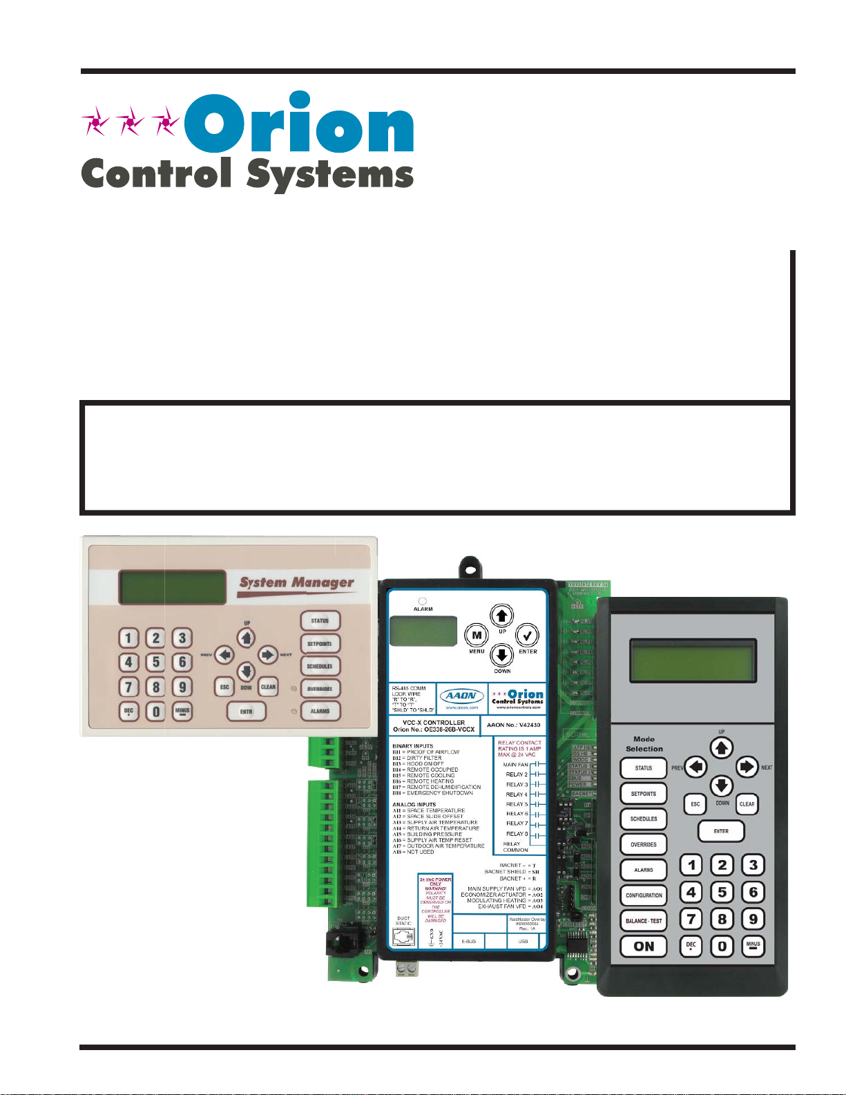
VCC-X Operator Interface SD
3
Page 4
SYSTEM CONNECTION
Modular Service Tool SD
Modular Service Tool SD
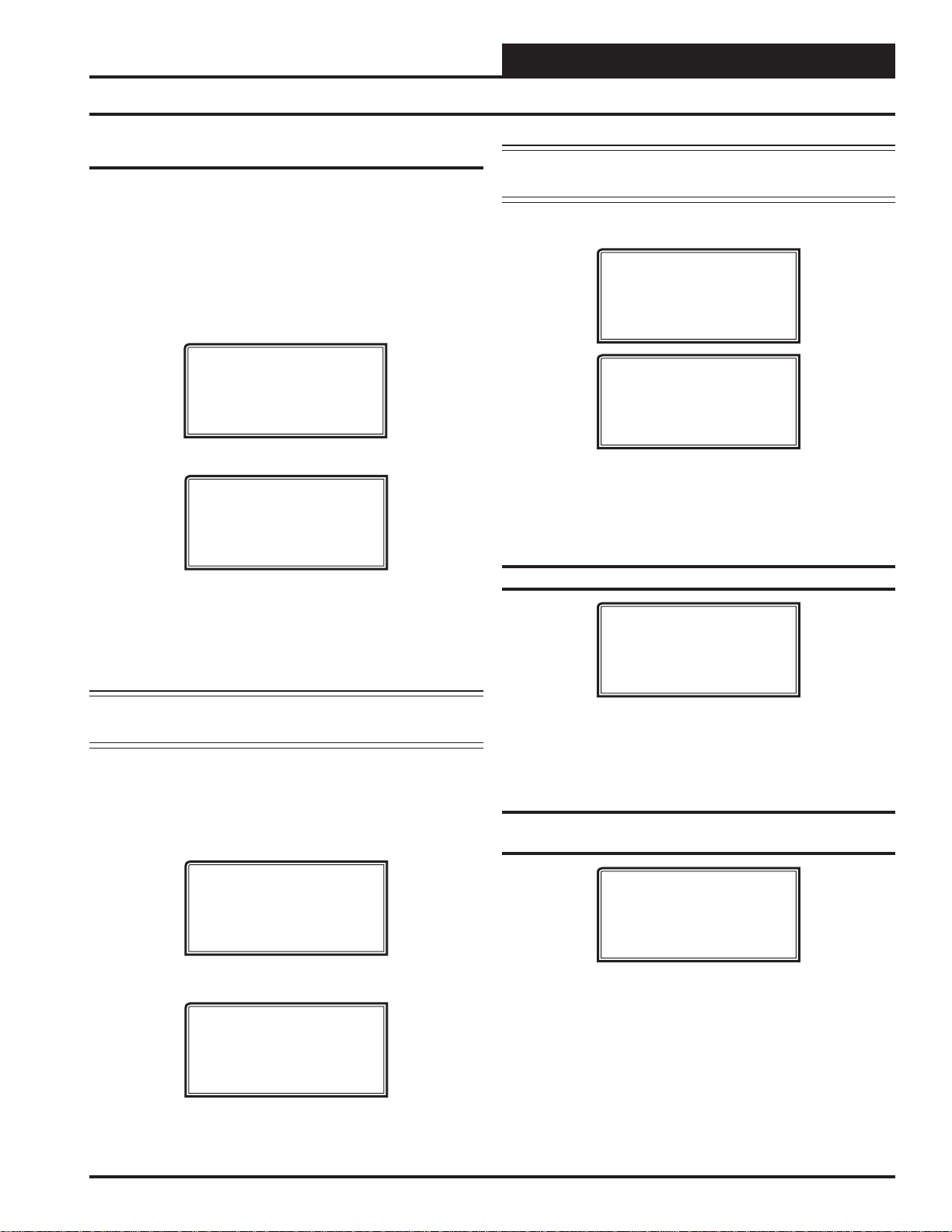
The OE391-12 Modular Service Tool is a system operator interface
that provides a direct link to enable the system operator to view the
status, confi gure, and adjust the setpoints of the VCC-X, VBC-X,
VCM, VCM-X, VCM-X E-BUS, RNE, SA E-BUS, VA V/CAV , MUA
II, or VAV/Zone Controller on the control system communications
loop. However, this manual only applies to VCC-X and VAV/Zone
Controllers. See note in the inside front cover for the list of manuals
that pertain to other controllers.
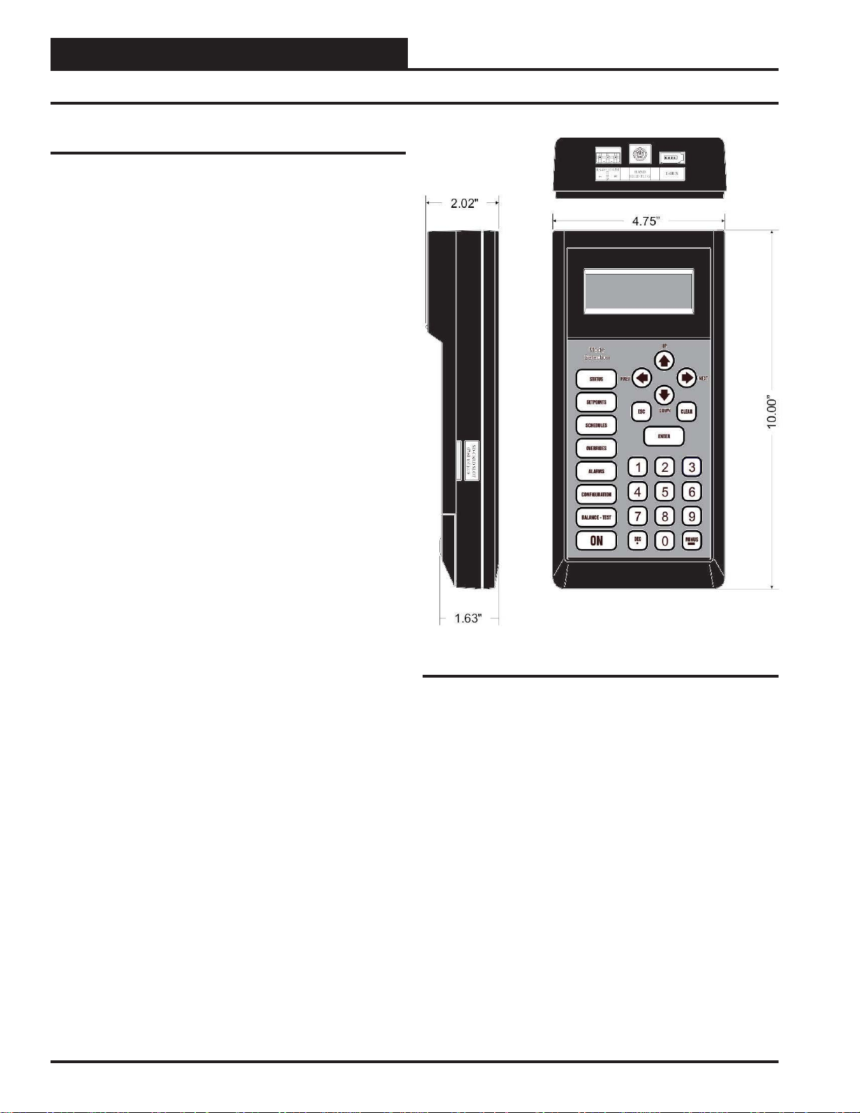
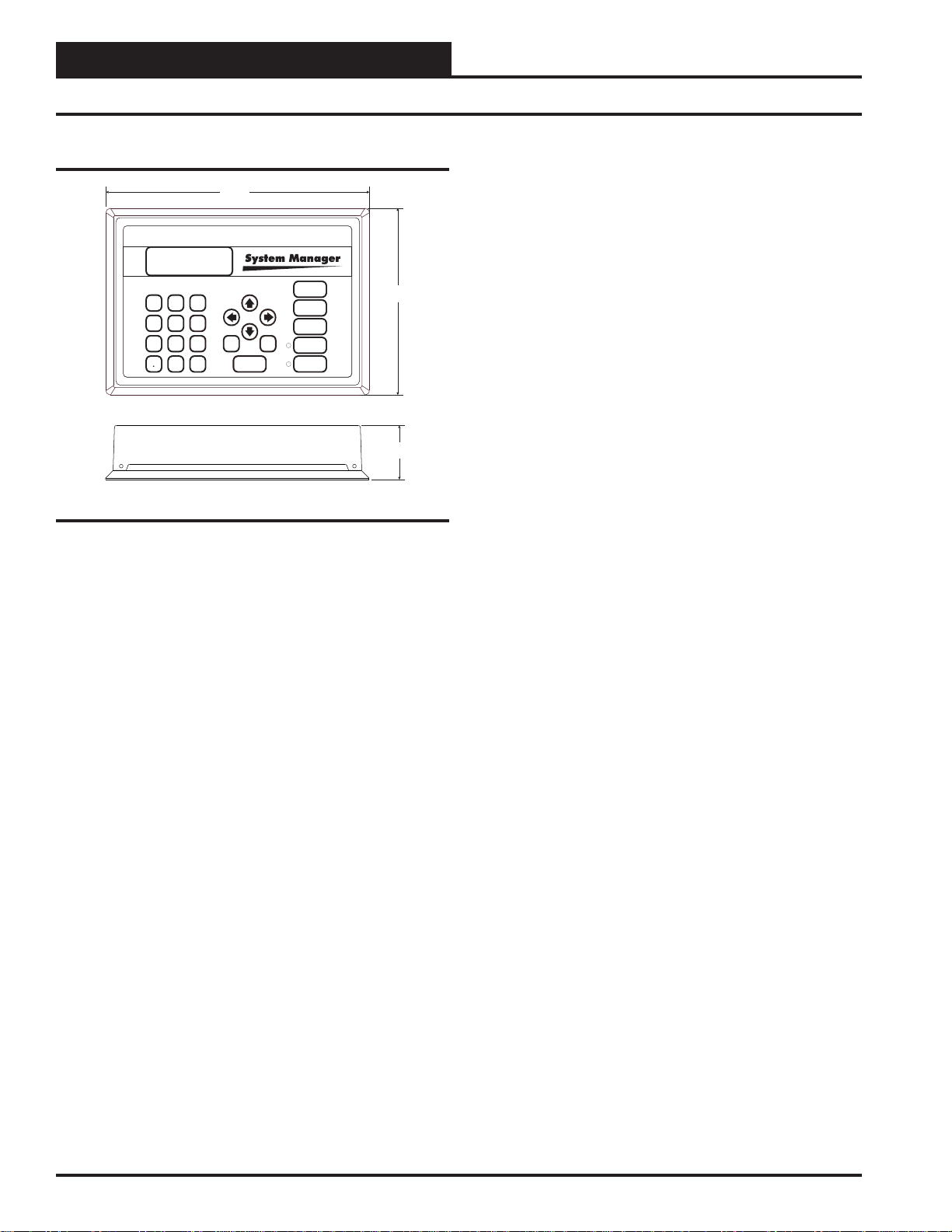
The Modular Service Tool is housed in an attractive black plastic
enclosure. The display area is covered with a clear plastic bezel for
protection of the display screen. The Modular Service Tool has a
4-line-by-20-character display panel with adjustable contrast control
and a 27-key membrane keypad for data selection and entry. All
keypad operations are simple and straight forward, utilizing noncryptic plain English language messages. Menu-driven programming
allows for easy setup and operation without the need for specialized
training. The Modular Service Tool is supplied with a programmable 4 Gigabyte SD memory card, (4) AA 1.5 V batteries, a wall
mount, a DC power supply, a mini-Din communication cable, and
an E-BUS communication cable. The mini-Din cable allows you
to connect the Modular Service Tool to any Orion controller which
has a mini-Din connector socket for programming, monitoring, and
troubleshooting purposes.
Zone
Zone
The Modular Service Tool is also equipped with an EBC E-BUS
port and an RS-485 three conductor terminal block port. The EBUS port and included E-BUS cable are used for updating E-BUS
Module software (described in Appendix C). The RS-485 port is
used for hard-wiring to older controllers that do not have a mini-DIN
connector socket.
The Modular Service Tool is designed to be hand-carried. Its rugged plastic housing provides superior protection for the electronic
components housed inside. The Modular Service T ool is a top-quality
service tool that will stand up to the demands of the typical job site
environment for many years.
Figure 1: Modular Service Tool SD Dimensions
4
VCC-X Operator Interface SD
Page 5
SYSTEM CONNECTION
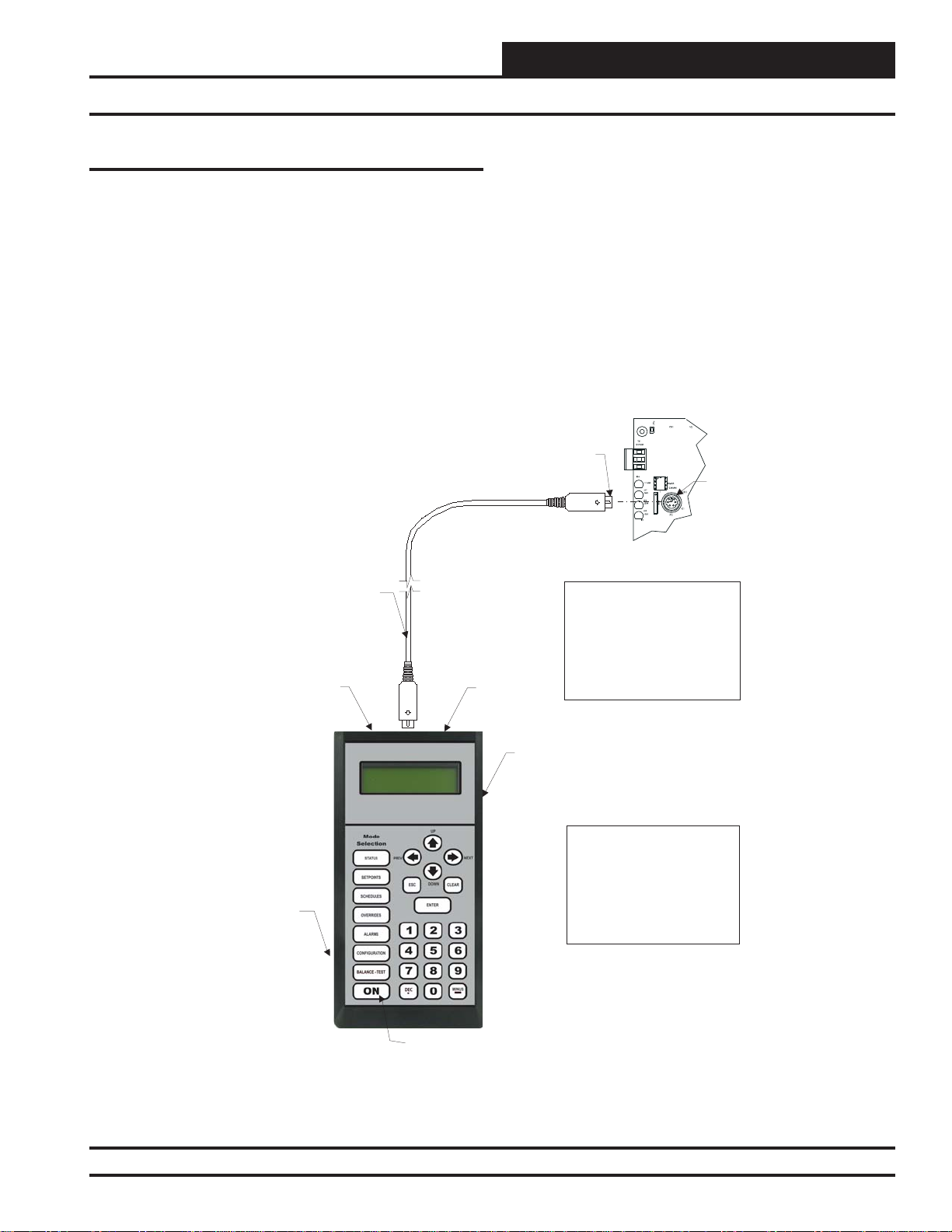
Modular Service Tool
Modular Service Tool
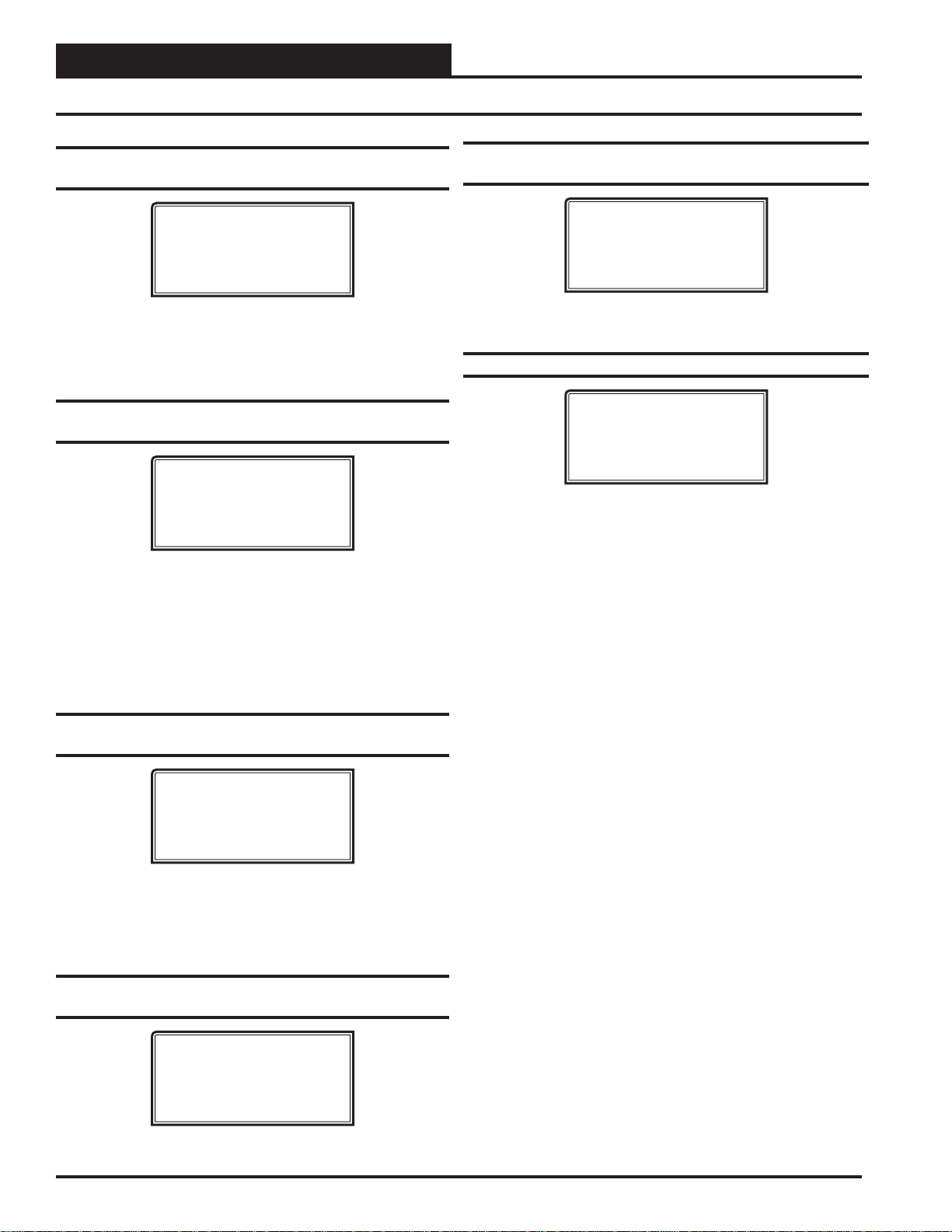
Whether you have a Stand Alone, Interconnected, or Networked
VCC-X Control System, the Modular Service T ool always connects
to the controller via a prefabricated cable that is supplied with the
service tool. The Modular Service Tool cable is terminated on both
ends with a mini-DIN connector. Attach one end to the Modular
Service Tool and the other end to the mini-DIN connector on the
controller. If this is an Interconnected System, all controllers that
are interconnected with communications cable can be programmed
from any controller on the loop. If this is a Networked System, all
controllers on the entire Networked System can be programmed
from one controller.
Male DIN Connector
Connector Cable
RS-485
Port
Be sure that the Modular Service T ool has fresh batteries installed or
that it is connected to a power source using the supplied power pack
before attempting any programming of the controller. See Figur e 2
for connection details.
Female DIN
Connector
Typical Controller Board
EBC
E-BUS
Port
The Modular Service Tool Can Be
Connected To
Or VAV/Zone Controller By
Plugging One End Of The
Supplied Cable Into the
Modular Service Tool DIN
Connector And The Other End
Into The DIN Connector On The
Controllers.
A Unit Controller
SD Memory Card
Figure 2: Modular Service Tool SD
VCC-X Operator Interface SD
Power On Button
Modular Service Tool SD
Be Sure The Modular Service
Tool Is Connected ToThe
Supplied Power Pack Or Has
Fresh Batteries Installed Before
Attempting Programming Of The
Controller. Be Sure The Power Is
Turned Off On The Modular
Service Tool Before Connecting
The Cable To The Controller.
5
Page 6
SYSTEM CONNECTION
Modular System Manager SD
Zone
Zone
Modular System Manager SD
9.00"
13
2
5
6
4
708
9
DEC
MINUS
-
UP
PREV
ESC
DOWN
ENTER
Figure 3: Modular System Manager SD Dimensions
STATUS
SETPOINTS
NEXT
SCHEDULES
CLEAR
OVERRIDES
ALARMS
6.25"
1.81"
The OE392-12 Modular System Manager SD provides a direct
link to enable you to view the status and adjust the setpoints of the
VCC-X, VCB-X, VCM-X, VCM-X E-BUS, RNE, SA E-BUS, VCM,
VAV/CAV, MUA II or VAV/Zone Controller on the control system
communications loop. The System Manager SD is housed in a beigecolored plastic enclosure. The System Manager has a programmable
4 Gigabyte SD card and is equipped with a 4-line-by-20-character
backlighted display panel and a 24-key membrane keypad for data
selection and entry. All keypad operations are simple and straight
forward, utilizing non-cryptic plain English language messages.
Menu-driven programming allows for easy setup and operation
without the need for specialized training. The System Manager also
has 2 integral LEDs for user notifi cation of system alarm condi-
tions and override initiations. Protection from unauthorized users
is provided by the System Manager’s integral multi-level passcode
authorization programming.
On a Networked System, the Modular System Manager is connected
to the communications and power loop of the system via modular
cables that simply plug into the System Manager board and the
Power/Comm Distribution Board. This virtually eliminates wiring
errors and makes installation fast and easy. When it is to be connected to a Stand-Alone system, a cable with modular connectors
on one end and stripped wire ends on the other end is provided to
facilitate connecting communications and power to the Modular
System Manager from the 24 VAC power source and the HVAC
unit controller communication wiring terminals.
The Modular System Manager is designed for wall mounting. Mounting holes are provided to attach the Modular System Manager to a
standard handy box. It is recommended that the System Manager be
mounted at approximately eye level to allow for ease of programming and reading of the display. The System Manager is typically
mounted in the building manager’s or superintendent’s offi ce or in
an equipment room. The attractive enclosure is quite suitable for
mounting in any location.
6
VCC-X Operator Interface SD
Page 7
SYSTEM CONNECTION
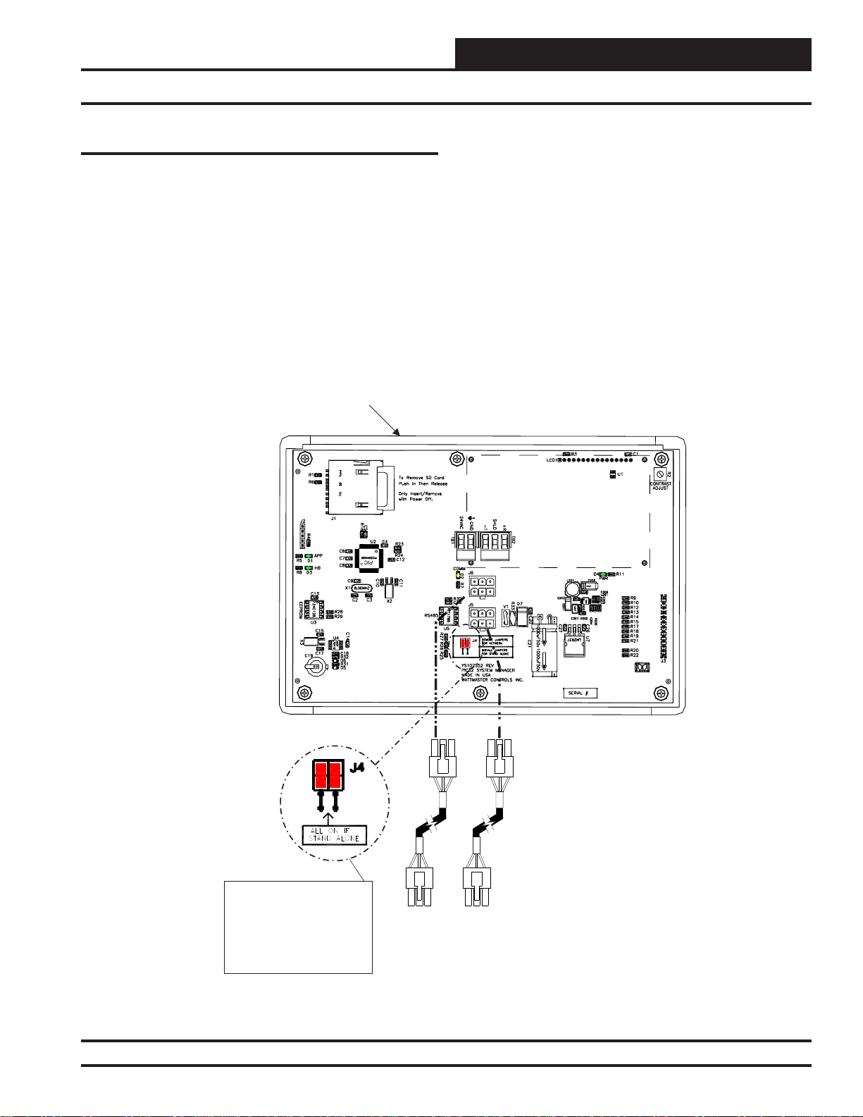
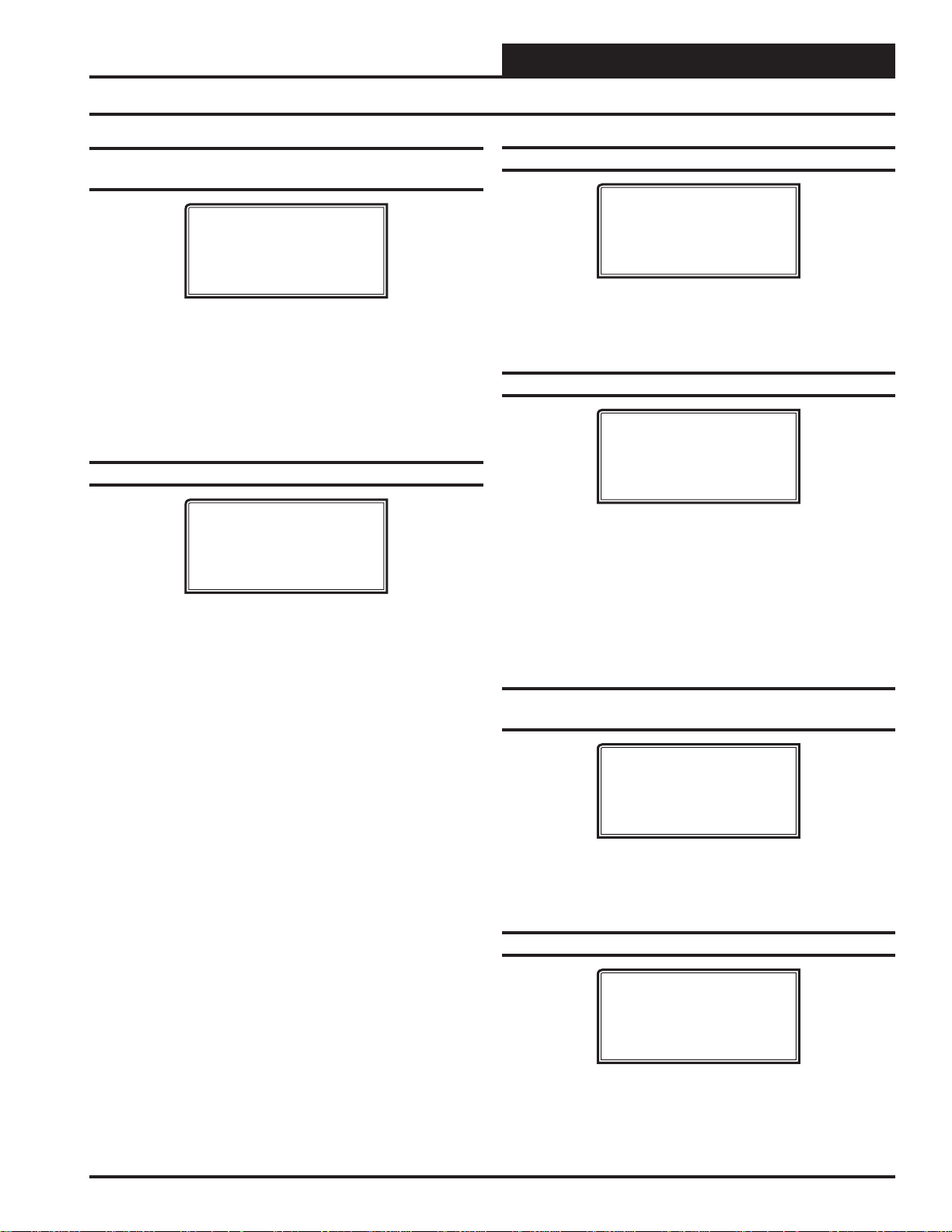
Modular System Manager SD Network Connection
Network Connection
As previously described, when you are connecting the Modular
System Manager to a Networked System, the Modular System
Manager is connected to the communications and power loop of
the system via modular cables. These cables simply plug into the
System Manager board and to any device with modular connectors
on any local loop on the system. Devices with modular connectors
include the Power/Comm Distribution Board, VA V/Zone controller ,
and MiniLink Polling Device. By using these plug-in connections,
wiring errors are virtually eliminated and system installation is fast
and easy. See Figure 4 below for typical connection information.
See Figure 5 on page 8 for typical Power/Comm board wiring and
connection information.
Modular System Manager SD
Back View
GB
4
When the System Manager is to be connected to a Stand Alone
system, a 12-foot cable with modular connectors on one end and
stripped wire ends on the other end is provided for this purpose. This
is used to facilitate connecting communications and power wiring
to the Modular System Manager from a 24 VAC power source and
to the HVAC unit controller communication wiring terminals. See
Figure 6 on page 9 for wiring details. If the supplied cable wire is
not long enough for your installation, a standard modular cable of
the correct length can be purchased through WattMaster and one of
the modular connectors can be cut off to allow for the transformer
and communication terminal wiring connections. It is recommended
that you do not splice the communications wire if at all possible.
The transformer should be rated at 6 VA minimum power output.
NOTE: For Stand-Alone
Installations (No CommLink
or MiniLink), All TERM
Jumpers Must Be ON.
For All Applications With
CommLink(s) Or MiniLink(s),
All Jumpers Must Be OFF.
Figure 4: Modular System Manager SD - Network
VCC-X Operator Interface SD
All Modular Power/Comm
Cables Are To Be
WattMaster Part Number
PCC-xx Or PCCE-xx
Cables.
Power/Comm Cables To
Power/Comm
Board, MiniLink Polling Device
Or VAV/Zone Controllers On
Local Loop.
Distribution
7
Page 8
SYSTEM CONNECTION
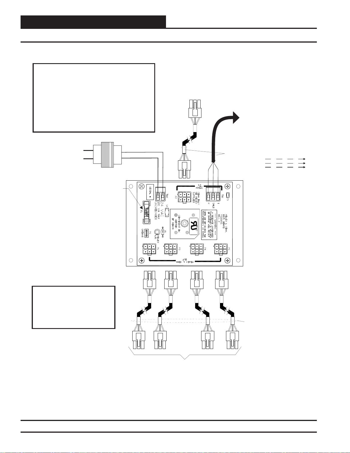
Power/Comm Board Wiring
Zone
Zone
WARNING!
DO NOT GROUND THE 24V TRANSFORMER
THAT IS TO BE USED WITH THE POWER/COMM
BOARDS. GROUNDING OF THE TRANSFORMER
WILL DAMAGE THE POWER/COMM BOARD
AND ALL BOARDS CONNECTED TO IT. A
SEPARATE TRANSFORMER MUST BE USED
FOR EACH POWER/COMM BOARD. NO
EXCEPTIONS. DO NOT CONNECT ANY OTHER
DEVICES TO THE TRANSFORMER USED FOR
THE POWER/COMM BOARD!
Line Voltage
24VAC
24VAC Transformer (By Others)
4 Amp Slow Blow Fuse
A Power/Comm
Connect With The MiniLink PD Instead
2 Conductor Twisted Pair With Shield
Using
Cable A Power/Comm
. You Can Also Use
Cable To Connect With
Board, A System Manager Or A VAV/Zone
Controller.
Cable Can Be Used To
Another Power/Comm
Local Loop RS-485
C US
R
Of
If Desired, Instead Of Using A
Power/Comm Cable, You Can Use 2
Conductor Twisted Pair With Shield
Cable To Connect To The Power/
Comm Board From The Unit
Controller, MiniLink PD, Or Another
Power/Comm Board.
All Comm Loop Wiring Is
9600 Baud
T
SH
R
Straight Thru
T
SH
R
T
T
SH
SH
R
R
NOTE:
Diagram Shown Is For Wiring Of
Power/Comm Board When Used
For Connecting Local Loop Devices
Such As VAV/Zone Controllers,
System Manager(s) and Other
Power/Comm Boards.
System Manager, Or VAV/Zone Controllers On Local Loop Only.
Figure 5: Typical Power/Comm Board Wiring
8
Power/Comm Cable To Power/Comm
Other Board(s),
VCC-X Operator Interface SD
Local Loop RS-485
9600 Baud
Page 9
Modular System Manager SD
Back View
GB
4
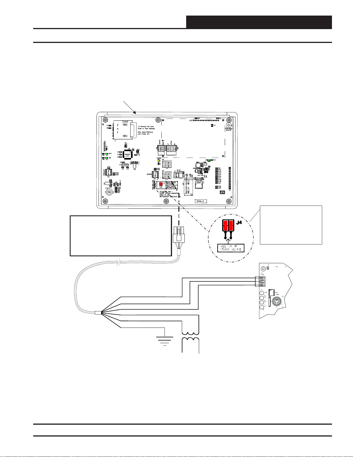
SYSTEM CONNECTION
Stand Alone Connection
NOTE: If Desired A Power/Comm Board As
Used With The Networked System Can Be
Installed And Wired Instead Of Using The
Pigtail Cable Wiring Shown Below. See The
Networked System Wiring Diagram For
Details.
Use Supplied Modular Cable
With Stripped Ends For
Connection To Terminal Block
And Transformer
WHITE (T)
DRAIN WIRE (SHLD)
BLACK (R)
RED (24 VAC)
BROWN (GND)
GREEN (GND)
Rated For 6 VA Minimum
Class 2 Transformer
NOTE: For Stand-Alone
Installations (No CommLink
or MiniLink), All TERM
Jumpers Must Be ON.
For All Applications With
CommLink(s) Or MiniLink(s),
All Jumpers Must Be OFF.
T
SHLD
R
Controller Board
Figure 6: Modular System Manager SD - Stand Alone
VCC-X Operator Interface SD
9
Page 10
MODULAR SERVICE TOOL SD
Modular Service Tool Keys
Operator Interfaces
In order to confi gure and program the VCC-X Controller , you must
have an Operator’s Interface or a personal computer with the Prism
2 computer front-end software installed. Two different Operator
Interfaces are available for programming of the VCC-X Controls
System—the Modular Service T ool SD and/or the System Manager
TS. These devices allow you to access the status and setpoints of
any controller on your communications loop. This manual describes
the Modular Service Tool SD. If using the System Manager TS II,
please see the System Manager TS II T echnical Guide. If using Prism
2, please see the Prism 2 Technical Guide.
The Modular Service Tool allows you to view any input or output
status and change any setpoint to fi ne-tune the operations of the
total system. All keypad operations are simple and straightforward,
utilizing non-cryptic plain English messages.
Display Screens & Data Entry Keys
See the chart below for a list of the keypad descriptions and functions.
Keypad
Function
Description
ESC
ENTER
Clear
Minus
DEC
Use this key to exit from screens or
from data entry or to return to the
Main Screen from any screen in the
system.
Use this key to enter a new value.
If a data entry mistake is made,
press this key to clear the data entry
fi eld and start over. This key also
turns off the power to the Service
Tool when on the
Main Screen
If a setpoint with a negative value
is required, press this key for the
minus sign.
Press this key when entering data
that requires a decimal point.
Use these keys to change values
in the Confi guration Screens as
prompted.
Use these keys to step backward or
forward through the screens.
Mode Selection Buttons
The Modular Service Tool is provided with “Mode Selection But-
tons.” These buttons give you instant access to the specifi c mode
desired without having to scroll through several menu screens to
get there.
Button
Description
STATUS
SETPOINTS
SCHEDULES
OVERRIDES
ALARMS
“Alarms” screen. See the “Alarms
CONFIGURATION
BALANCE-TEST
NOTE:
(1) The Modular Service Tool will only search the Overrides
one loop at a time. You must enter the Loop number and the
MiniLink PD unit ID (60).
Table 2: Button Descriptions
Function
Pressing this button takes you
directly to the controller
“Status” screens.
Pressing this button takes you
directly to the controller
“Setpoints” screens.
Pressing this button takes you
directly to the controller
“Schedules” screens.
Pressing this button takes you
directly to the controller “Overrides” screen. See the “Override
Button” section on page 21 for a
description of this function.
See Note 1 below.
Pressing this button takes you
directly to the controller
Button” section on page 20 for a
description of this function.
Pressing this button takes you
directly to the controller
“Confi guration” screens.
Pressing this button takes you
directly to the controller
“Balance-Test” screens.
Table 1: Keypad Descriptions
10 VCC-X Operator Interface SD
Page 11

MODULAR SERVICE TOOL SD
Initialization & Setting the Time & Date
Modular Service Tool Initialization
Modular Service Tool Initialization Screen and
Setup Screens
After connecting the Service T ool to the controller with the supplied
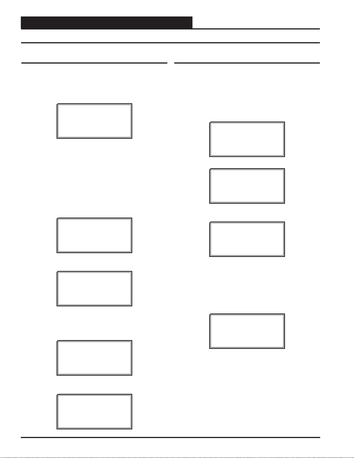
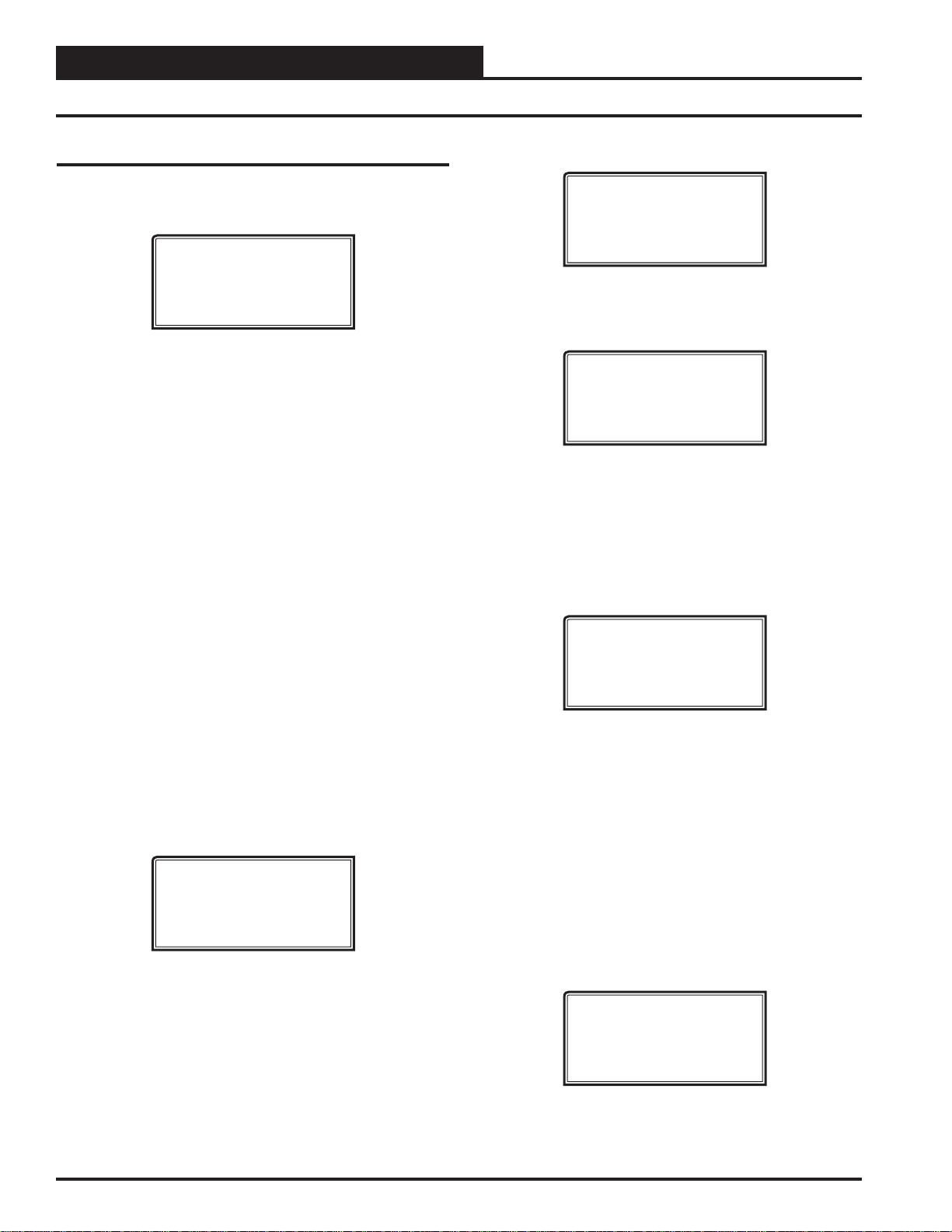
cable, press <ON>. The Initialization Screen will appear followed
by the Setup Screens as shown below. If there is no SD card installed, the second screen will display, “No SD Card Connected!
Powering Down!”
Initializing
Service Tool vX.XX
WattMaster Controls
1) Set Time & Date
2) Communications
NEXT) More Options
ESC) Exit Menu
3) Energy Saving
4) Update Software
NEXT) More Options
ESC) Exit Menu
Although the times are displayed on the Main Screen in a standard
12-hour format, you must program them using the 24-hour military
format. If you confi gured the VCC-X Controller to use its own
Internal Schedules, the Occupied/Unoccupied modes are calculated
on the basis of the current real time clock reading.
The two screens that follow will appear. T o scroll through the fi elds,
press <> or
<ENTER>. In order to save a new value, you must
press <ENTER>.
Program Time/Date
Day (Sunday=0): X
Enter Hr. (0-23): XX
Enter Minutes : XX
Day - Enter the Day of the Week (0 to 6)
Sunday = 0
Hours (Hr) - Enter Hours in 24-Hour Military Format
(1700 = 5:00 PM)
Minutes - Enter the Minutes
(0 to 59)
Programming the Date
NOTE: Once you press <ESC> while at the Setup Screens
shown above, you can access them again by pressing
<NEXT> or cycling power.
Setting The Time & Date
The Modular Service Tool is equipped with a real time clock chip
allowing it to maintain the correct time. Once you have programmed
the correct time and date, the information is broadcast globally to
all controllers on the entire system.
NOTE: If you are in a time zone that has daylight savings,
you will need to manually adjust the time twice a year.
Programming the Time
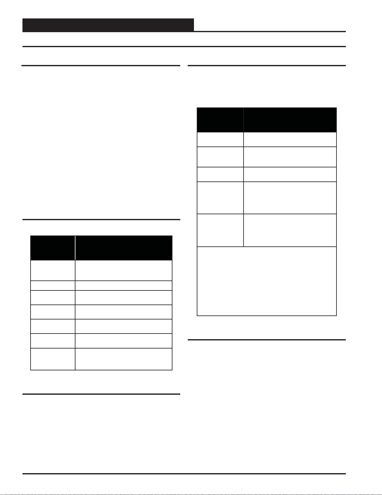
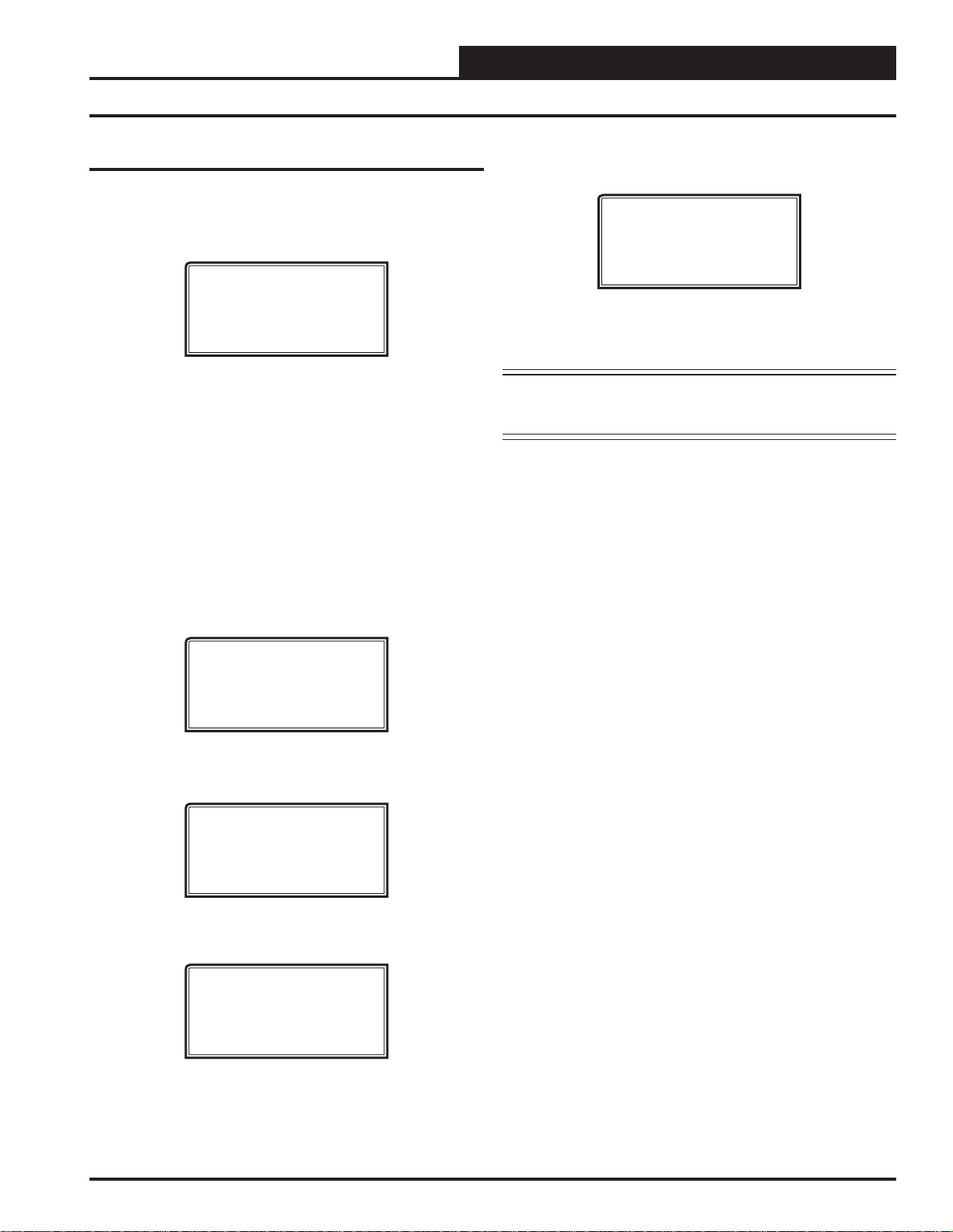
From the Setup Screen shown below, press <1> on your keypad to
access the Set Time & Date Scr eens. (Y ou may have to press <NEXT>
to access this screen).
1) Set Time & Date
2) Communications
NEXT) More Options
ESC) Exit Menu
To scroll through the fi elds, press <> or <ENTER>. In order to
save a new value, you must press <ENTER>.
Program Time/Date
Month (1-12): XX
Day (1-31): XX
Year (00-99): XX
Month - Enter the Month (1 to 12)
Day - Enter the Day of the Month (1 to 31)
Year - Enter the current Year with two digits
(00 to 99)
When you have fi nished programming the time and date, press
<ESC> to return to the Setup Screen shown below.
1) Set Time & Date
2) Communications
NEXT) More Options
ESC) Exit Menu
VCC-X Operator Interface SD
11
Page 12
MODULAR SERVICE TOOL SD
Setting the Operating Mode and Energy Saving Timer
Setting the Operating Mode
The Operating Mode is displayed on the last line of the Main Screen
as shown below. The factory default setting for the Service Tool is
LS (Low Speed) Stand Alone Mode. LS Stand Alone Mode is
the correct confi guration for the VCC-X Controller when in Stand
Alone Mode.
Service Tool SD vX.XX
Wednesday Operations
01/16/15 02:21 PM
LS Stand Alone *00*
If you are using this Service T ool on a communications loop and have
an installed MiniLink PD or CommLink, you will need to change
the setting to LS (Low Speed) Network Mode.
If you are using a VCC-X Controller that is set for high speed, you
will need to change the setting to HS (High Speed) Stand Alone
Mode or HS (High Speed) Network Mode.
If your display indicates a different mode than the one you need,
press <2> at the Setup Screen shown below. You may have to press
<NEXT> to access this screen.
1) Set Time & Date
2) Communications
NEXT) More Options
ESC) Exit Menu
Setting the Energy Saving Timer
The Modular Service Tool has a built-in timer that can be programmed to shut the Service Tool off after a specifi ed period of
time if no buttons are pressed. This is a very useful feature if you
are powering the Service Tool from the internal batteries.
To set the Energy Saving Timer,
Screen and
<3> at the second Setup Screen shown below. (You may
have to press <NEXT> to access these screens).
1) Set Time & Date
2) Communications
NEXT) More Options
ESC) Exit Menu
3) Energy Saving
4) Update Software
NEXT) More Options
ESC) Exit Menu
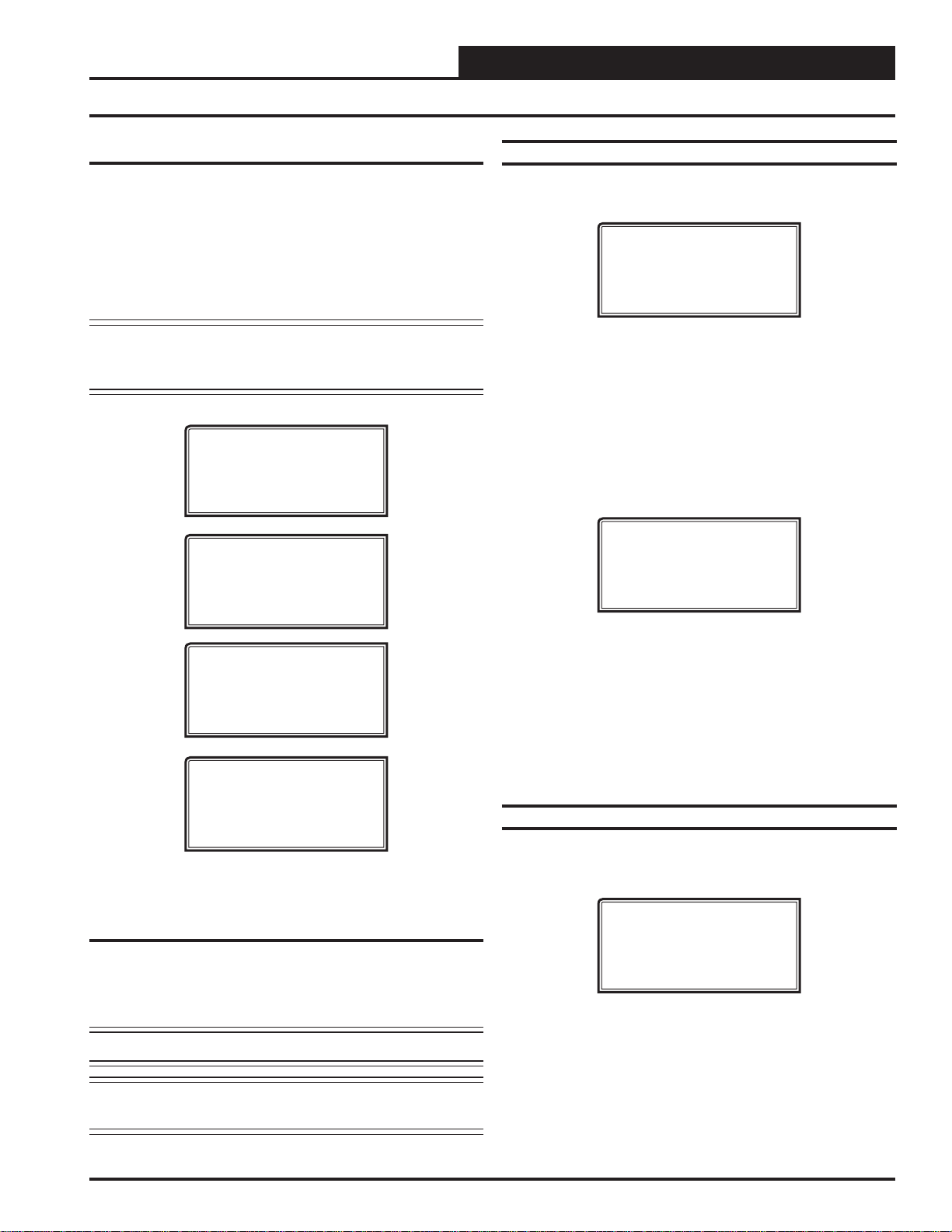
The Energy Saving Screen will appear as shown below:
Energy Saving
Automatic Power Down
Minutes: xx
Press ESC to Exit
press <NEXT> at the fi rst Setup
The Communications Screen will appear as shown below.
Stand Alone Mode
Lo Speed Connection
Use Left/Right Arrow
To Change Selections
Press <> or <> to select the proper mode of operation.
When you have made your selection, press
screen will appear.
You Have Changed The
System Mode
Press Any Key To
Continue
Press any key to continue. The Setup Screen will appear as shown below:
1) Set Time & Date
2) Communications
NEXT) More Options
ESC) Exit Menu
<ENTER>. The following
Enter the number of minutes you want the Service Tool to stay active before it automatically powers down and press <ENTER>. To
cancel the automatic power down, enter <99> and press <ENTER>.
After you have entered a number between 1 and 99 minutes,
<ESC> to exit the screen.
The Setup Screen will appear again as shown below:
1) Set Time & Date
2) Communications
NEXT) More Options
ESC) Exit Menu
press
12 VCC-X Operator Interface SD
Page 13

MODULAR SERVICE TOOL SD
Alarm and Override Search
Modular Service Tool Alarm Search
NOTE: When you press the <ALARMS> button on the Modu-
lar Service Tool, it will search only the unit ID that
you have entered; therefore, you must search each unit
individually to access all alarms for that controller.
To search for alarms,
Main Screen. The Unit Selection Screen will be displayed.
Enter the Unit ID of the controller the Service Tool is connected to
and press <ENTER>. Once communication is established, the *00*
message will go away. Then
NOTE: If the *00* remains, it indicates a communication
failure to the controller.
One of the following screens will appear:
press < ALARMS> while on any screen but the
Enter Unit Address
Then Press Enter
Selected Unit #_1
Press Down
press <>.
VCC-X V.XXX
NO ALARMS
Modular Service Tool Override Search
When a space sensor with override option is used with any VAV/
Zone or Unit Controller, the Modular Service Tool can determine
and report any controllers that are currently operating in an override
condition on a specifi c Loop by entering a Loop ID number and
then doing a search.
NOTE: When you press the <OVERRIDES> button on the
Modular Service Tool, it will search only the Loop
number that you enter; therefore, you must search
each loop individually to access all overrides.
To access the
Modular Service Tool’s keypad. A screen will appear asking you
to enter the unit ID.
Enter the Unit ID for the MiniLink PD (MLPD) of the loop you
wish to search and press <ENTER>. The MLPD is always address
60 on each loop. So the unit ID of any particular MLPD would be
the loop number followed by 60. In the example above, Loop 1,
address 60 has been entered. Once communication is established,
the *00* message will go away. Then
NOTE: If the *00* remains, it indicates a communication
Overrides Screen, press <OVERRIDES> from the
Enter Unit Address
Then Press Enter
Selected Unit #160
Press Down
press <>.
failure to the controller.
VCC-X V.XXX
ALARMS PRESENT
SCROLL DOWN TO VIEW
Press <> to scroll through all the alarms for the controller that the
Modular Service Tool is connected to.
To clear any alarms that are found, you must fi x the problem indicated
in the alarm. Once the problem is fi xed, the alarm will clear from
the screen the next time the unit is polled.
If communications are successful, one of the following screens
will appear:
VCC-X V.XXX
NO OVERRIDES
VCC-X V.XXX
OVERRIDES PRESENT
SCROLL DOWN TO VIEW
After the Service Tool completes its search, it will post a message
to tell you if there are overrides present. If there are overrides, press
<> and all units on the loop will be listed showing ‘Override: Yes
or No.’ Press <OVERRIDES> again to access overrides on a different
loop. Enter the Unit ID of the MLPD of that loop.
VCC-X Operator Interface SD
13
Page 14

MODULAR SERVICE TOOL SD
Schedules and Holidays
Scheduling
You can access the Unit Controller Scheduling Screens by pressing
<SCHEDULES>. The Unit Selection Screen will be displayed.
Enter Unit Address
Then Press Enter
Selected Unit #_1
Press Down
Enter the Unit ID of the controller the Service Tool is connected to
and press <ENTER>. Once communication is established, the *00*
message will go away. Then
NOTE: If the *00* remains, it indicates a communication
failure to the controller.
Press the <> button and then press <ENTER> to access the
scheduling function you wish to view.
VCC-X Schedule Menu
Schedule Override
Week Schedules
Holidays
press <>.
The screens will step through the Start Time and then the Stop T ime
for each day of the week. You can quit at any point in the process by
pressing <ESC>. There are two Start/Stop events available per day,
so the screen will show which event is being programmed. If you
need only one event, keep Event #2’s times set at ZERO.
All times are in 24-hour military format, so 5:00 PM would be
entered as 1700.
If both the Start and Stop Times are ZERO, the schedule is in a
continuous OFF mode. (Also, use for Remote Forced Occupied
applications using the Forced Occupied Binary Input.)
If both the Start and Stop Times are 2359, the schedule is in a continuous ON mode.
NOTE: The second line displays which day of the week is
currently being programmed. The day of the week
automatically increments as you exit the Event #2
screen for the day and continue to the next day’s Event
#1 screen.
CAUTION: The controller ships with all schedules set to
zero so that the controller will not attempt to heat
or cool before you have confi gured the system.
Week Schedules
Holiday Start/Stop Day Selection
Event #1
VCC-X Schd ID #
Sunday Event #1
Start Time: XXXX
Stop Time: XXXX
Event #2
VCC-X Schd ID #
Sunday Event #2
Start Time: XXXX
Stop Time: XXXX
The screens will step through the fourteen possible holidays, one
period at a time. Line 2 shows which holiday is currently being
VCC-X Schd ID #
Holiday # 1
Start Mon/Day: XXXX
[ July 4
VCC-X Schd ID #
Stop Mon/Day: XXXX
[ July 5
th
= 704 ]
Holiday # 1
th
= 705 ]
programmed. Since a holiday period can encompass more than one
If you are using the internal scheduling capability of the Unit Controller, set the schedule hours and holiday periods from the menu
shown above. You can also force the unit to operate continuously in
occupied or unoccupied mode by selecting the Schedule Override
menu item and entering the desired command.
If you are using an external contact closure to signal the occupied
mode, you must access the Week Schedule Screens and set all start
day, you need to program the day the holiday starts and the day the
holiday ends. If your holiday only lasts one day, simply set both the
Start Day and the Stop Day to the same value. Remember to combine
the month and day into a single four-digit value.
EXAMPLE: 704 = July 4
th
(NOTE: Leading zero not
required)
1225 = December 25
th
and stop times to zero to prevent the internal schedule from turning
the equipment on when you don’t want it to operate.
14 VCC-X Operator Interface SD
Page 15

MODULAR SERVICE TOOL SD
Holiday Scheduling and Schedule Override
Holiday Start/Stop Times
VCC-X Schd ID #
Holiday Schedule
Start Event #1: XXXX
Stop Event #1: XXXX
VCC-X Schd ID #
Holiday Schedule
Start Event #2: XXXX
Stop Event #2: XXXX
The fourteen holidays all use the same Start and Stop times which
you program on this screen and the next. You must enter the time
in 24-hour military format, the same as a regular week schedule.
Normally, the holidays will operate in an unoccupied mode or a
reduced schedule mode. There are two start/stop events available on
holidays to match the standard schedule number of events.
Schedule Override
VCC-X Ovrd ID #
Schedule Override
Enter Override: X
[0=Auto 1=ON 2=OFF]
If you want to force the unit to operate in a continuous Occupied
or Unoccupied mode, select this menu item to activate the desired
method. If a Schedule Override is active, all other methods of
schedule control are ignored (Push-Button, Internal, and Remote).
As you can see on the last line of the display,
tinuously in the Occupied Mode or <2> to run continuously in the
Unoccupied Mode. T o restore normal schedule operations, enter <0>.
This override remains in effect until canceled and does not time-out
like the Output Overrides do after 10 minutes of no communications.
NOTE: Do not use the Force OFF mode in place of setting
all the week schedules to ZERO if you are using a
Remote Signal for your scheduling since the Override
has priority over the Remote Signal.
enter <1> to run con-
VCC-X Operator Interface SD
15
Page 16
MODULAR SYSTEM MANAGER SD
System Manager SD Keys and Buttons
Zone
Zone
Operator Interfaces
In order to confi gure and program the Orion System controllers,
you must have an Operator’s Interface or a personal computer with
the Prism 2 computer front-end software installed. Three different
Operator Interfaces are available for programming of the Orion
Controls System—the Modular Service Tool SD, the Modular System Manager SD, and/or the System Manager TS II. These devices
allow you to access the status and setpoints of the controllers on your
communications loop. This manual describes the Modular System
Manager SD. If using the System Manager TS II, please see the
System Manager TS II T echnical Guide. If using Prism 2, please see
the Prism 2 Technical Guide.
The Modular System Manager SD allows you to view any input or
output status and change any setpoint to fi ne-tune the operations of the
total system. All keypad operations are simple and straightforward,
utilizing non-cryptic plain English messages.
Display Screens & Data Entry Keys
See the chart below for a list of the keypad descriptions and functions.
Keypad
Function
Description
ESC
ENTER
Clear
Minus
DEC
Use this key to exit from screens or from data
entry or to return to the Main Screen from
any screen in the system.
Use this key to enter a new value.
If a data entry mistake is made, press this key
to clear the data entry fi eld and start over.
If a setpoint with a negative value is required,
press this key for the minus sign.
Press this key when entering data that re-
quires a decimal point.
Use these keys to change values in the Con-
fi guration Screens as prompted.
Use these keys to step backward or forward
through the screens.
Mode Selection Buttons
The Modular System Manager is provided with “Mode Selection
Buttons.” These buttons give you instant access to the specifi c mode
desired without having to scroll through several menu screens to
get there.
Button
Description Function
STATUS
SETPOINTS
SCHEDULES
OVERRIDES
ALARMS
NOTES:
(1) This button only functions when the system is confi gured for
“Network Mode” or “Multiple MGRS Mode.” It will not function
in “Stand Alone Mode.”
(2) The “Search for Units” function must be performed on the System
Manager upon initial system setup before this function will be available. See the “Network Mode & Multiple Managers Loop Search”
on page 20 of this manual for complete instructions on performing
a loop search.
Table 4: Button Descriptions
Pressing this button takes you directly to
the controller “Status” screens.
Pressing this button takes you directly to
the controller “Setpoints” screens and
“Confi guration” menu.
Pressing this button takes you directly to
the controller “Schedules” screens.
Pressing this button takes you directly to
the controller “Overrides” screen. See the
“Override Button” section on page 21 for a
description of this function.
See Notes 1 & 2 below.
Pressing this button takes you directly to
the controller “Alarms” screen. See the
“Alarms Button” section on page 20 for a
description of this function.
See Notes 1 & 2 below.
Table 3: Keypad Descriptions
16
VCC-X Operator Interface SD
Page 17
MODULAR SYSTEM MANAGER SD
Initialization & Setting the Time & Date
System Manager SD Initialization
System Manager SD Initialization Screen and
Setup Screens
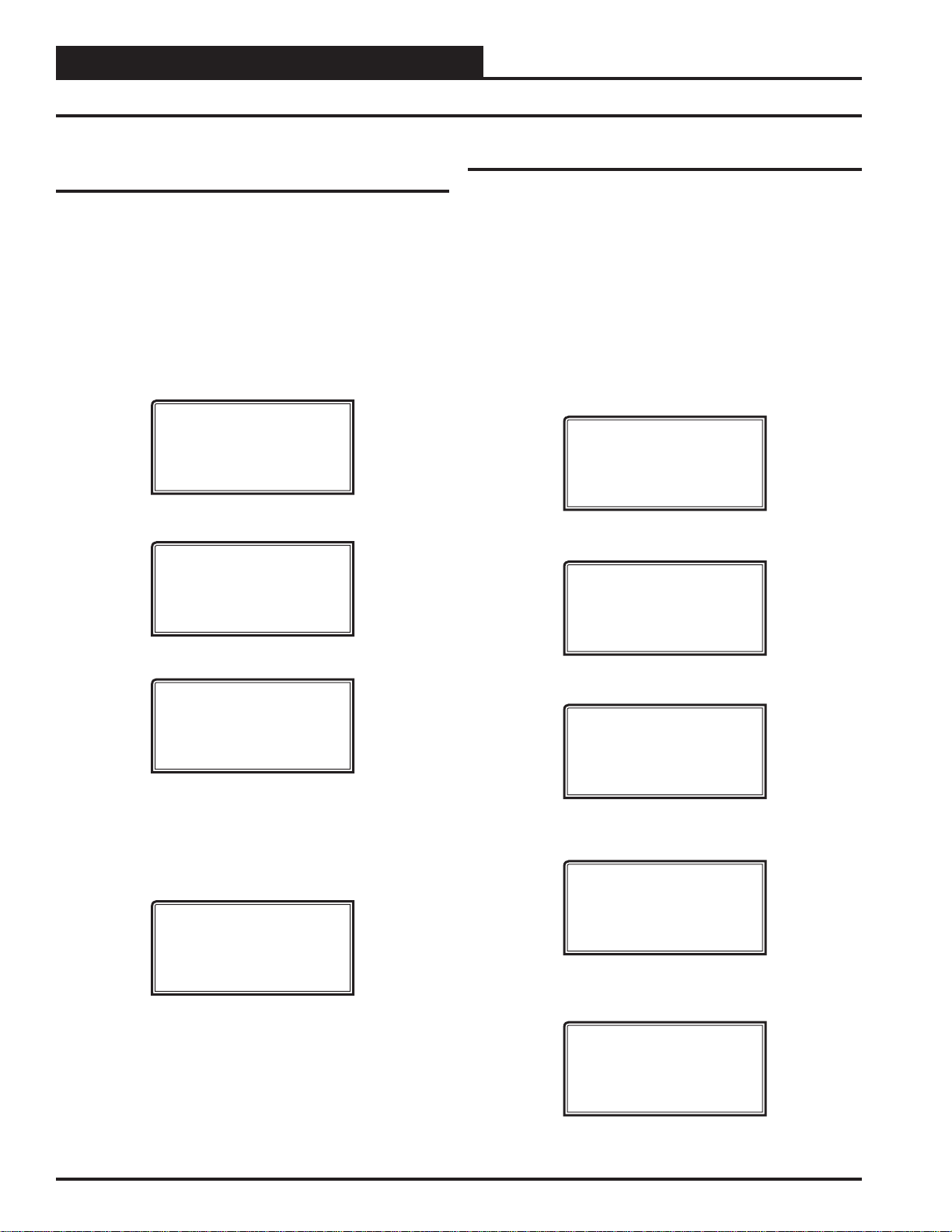
After connecting the System Manager to the controller with the
supplied cable, press <ON>. The Initialization Screen will appear
followed by the Setup Screens as shown below . If there is no SD card
installed, the second screen will display, “No SD Card Connected!
Powering Down!”
NOTE: After exiting these screens, you can access them again
by pressing <ESC> and then <> or by cycling
power.
INITIALIZING
System Manager SD
vX.XX
WattMaster Controls
1) Set Time & Date
2) Communications
NEXT) More Options
ESC) Exit Menu
Programming the Time
From the Setup Screen shown below, press <1> on your keypad to
access the Set Time & Date Screens.
1) Set Time & Date
2) Communications
NEXT) More Options
ESC) Exit Menu
Although the times are displayed on the Main Screen in a standard
12-hour format, you must program them using the 24-hour military
format. If you confi gured the Unit Controller to use its own Internal
Schedules, the Occupied/Unoccupied modes are calculated on the
basis of the current real time clock reading.
The two screens that follow will appear. T o scroll through the fi elds,
press <> or
<ENTER>. In order to save a new value, you must
press <ENTER>.
Program Time/Date
Day (Sunday=0): X
Enter Hr. (0-23): XX
Enter Minutes : XX
3) Change Passcodes
4) Loop Search
NEXT) More Options
ESC) Exit Menu
5) Alarm Search
NEXT) More Options
ESC) Exit Menu
Setting The Time & Date
The System Manager SD is equipped with a real time clock chip
allowing it to maintain the correct time. Once you have programmed
the correct time and date, the information is broadcast globally to
all controllers on the entire system.
NOTE: A Level 1 or Level 2 User can set the time and date.
NOTE: If you are in a time zone that has daylight savings, you
will need to manually adjust the time twice a year.
Day - Enter the Day of the Week (0 to 6)
Sunday = 0
Hours (Hr) - Enter the Hour (0-23) in
24-Hour Military Format
(13 = 1:00 PM)
Minutes - Enter the Minutes
(0 to 59)
Programming the Date
To scroll through the fi elds, press <> or <ENTER>. In order to
save a new value, you must press <ENTER>.
Program Time/Date
Month (1-12): XX
Day (1-31): XX
Year (0-99): XX
Month - Enter the Month (1 to 12)
Day - Enter the Day of the Month (1 to 31)
Year - Enter the current Year (0 to 99)
When you have fi nished programming the time and date, press
<ESC> to return to the Setup Screen.
VCC-X Operator Interface SD
17
Page 18
MODULAR SYSTEM MANAGER SD
Setting the Operating Mode
Zone
Zone
Setting the Operating Mode
The Operating Mode is displayed on the last line of the Main Screen
as shown below. The factory default setting for the System Manager
is LS (Low Speed) Stand Alone Mode.
System Manager SD
Wednesday Operations
01/16/15 02:21 PM
LS Stand Alone Mode
The System Manager must be confi gured for the correct mode of
operation for your system. There are 5 modes of operation available
for the Orion System—LS (Low Speed) Stand-Alone, HS (High
Speed) Stand-Alone, LS (Low Speed) Network, HS (High Speed)
Network, and LS (Low Speed) & HS (High Speed) Multiple
MGRS.
If you are using this System Manager on a communications loop
that doesn’t have a MiniLink PD or CommLink connected to it and
you have a single System Manager on your system, then you need
to operate in LS (Low Speed) Stand-Alone Mode. If you are using a VCC-X Controller or GPC-XP Controller that is set for high
speed, and you don’t have a MiniLink PD or CommLink connected
to the loop, then you will need to change the setting to HS (High
Speed) Stand Alone Mode.
The Passcode Clearance Screen will appear as shown below.
THIS ACTION REQUIRES
A SPECIAL HIGH LEVEL
PASSCODE CLEARANCE
Enter: XXXXXXX
Enter the seven digit passcode <2337377> to access the next screen.
You will then see the screen below displayed.
Stand Alone Mode
Lo Speed Connection
Use Left/Right Arrow
To Change Selections
Press <> or <> if you need to change the mode of opera-
tion to LS (Low Speed) Stand-Alone, HS (High Speed StandAlone, LS (Low Speed) Network, HS (High Speed Network,
LS (Low Speed) Multiple Manager or HS (High Speed)
Multiple Manager and then press
selection. If you are not using Multiple Manager Mode, press
<ESC> at the screen below and continue scrolling right and left.
<ENTER> to save your
If you are using the System Manager on a communications loop
and have an installed MiniLink PD or CommLink, you will need to
change the setting to LS (Low Speed) Network Mode. If you are
using a VCC-X Controller or GPC-XP Controller that is set for high
speed, and are using a MiniLink PD or CommLink, then you will
need to change the setting to HS (High Speed) Network Mode.
If you are using this System Manager on a communications loop,
have a MiniLink PD or CommLink installed, and have multiple System Managers, then you need to operate in Multiple MGRS Mode.
If your display indicates a different mode than the one you need,
press <2> at the Setup Scr een shown below. You will have to cycle
power to get to this screen or by
1) Set Time & Date
2) Communications
NEXT) More Options
ESC) Exit Menu
pressing <ESC> and <PREV>.
Multiple Manager
Unit Address: 0
Press ESC to Exit
For Multiple MGRS Mode, enter the address at which you want
this particular System Manager to be set.
When multiple System Managers are used on a local loop, each
must be set with a unique address different from any other device
on that loop. You must perform this same operation again for each
System Manager installed. If you want one of these System Managers to be able to indicate alarms and overrides for the entire system,
you must
System Manager.
Once you have the correct number per the display above displayed,
press <ENTER>. The following screen will appear telling you that
you have changed the system mode:
select either LS or HS Network Mode on that particular
You Have Changed The
System Manager Mode
Press Any Key To
Continue
18
Press any key on the keyboard to exit this screen.
VCC-X Operator Interface SD
Page 19
MODULAR SYSTEM MANAGER SD
Changing Passcodes
System Manager Passcodes
Changing the mode of operation, updating software, changing
schedules, and changing setpoints and confi gurations require pass-
code clearance. The screen below will appear if this action requires
passcode clearance.
THIS ACTION REQUIRES
PASSCODE CLEARANCE
Enter Passcode: XXXX
The System Manager has three levels of user access. All users can
view Status Screens. Level 1 users are limited to changing the Time
and Date and Operating Schedules. Level 2 users have complete
system access. Any status or setpoint fi eld can be read or reset from
the System Manager.
These two levels of passcodes are programmable by any Level 2
user. The default Level 1 passcode is “ 1111” and the default Level
2 passcode is “ 2222.”
If you wish to change either Level 1 or Level 2 passcodes, please
see the instructions that follow.
From the Main Status Screen,
The following screen will appear:
press <ESC> and then pr ess <PREV>.
Passcodes can only be changed by a Level 2 user. Enter the passcode
and press <ENTER>. The following screen will appear:
Enter New Passcode
Level 1.....: XXXX
Level 2.....: XXXX
[Must Be 4 Digits]
This screen allows you to enter new Level 1 and/or Level 2 passcodes. Passcodes must always be four digits in length, so the usable
range of numbers is 1000 to 9999.
CAUTION: If you change the Level 2 passcode and can-
not remember what it is, you will be locked
out of your system!
1) Set Time & Date
2) Communications
NEXT) More Options
ESC) Exit Menu
Press <> for the Next Menu. The following screen will be dis-
played:
3) Change Passcodes
4) Loop Search
NEXT) More Options
ESC) Exit Menu
Press <3> for Change Passcodes. The following screen will be
displayed:
THIS ACTION REQUIRES
PASSCODE CLEARANCE
Enter Passcode: XXXX
VCC-X Operator Interface SD
19
Page 20
MODULAR SYSTEM MANAGER SD
Loop Search and System Alarm Search
Zone
Zone
Network Mode & Multiple Managers
Loop Search
When the System Manager is confi gured for Network Mode, a loop
search must initially be performed for the System Manager to recognize alarms or overrides. Also, when you have a system that has
multiple System Managers and you have one of the System Managers
set to (63) Network Mode for alarm and override indication, you must
also perform a loop search for that System Manager. This allows
the System Manager to be aware of all alarms and overrides for all
local loops on the entire system.
To access the
and then press
Press <> for Next Menu. The following screen will be displayed:
Loop Search Scr een, from the Setup Screen, press <ESC>
<PREV>.
1) Set Time & Date
2) Communications
NEXT) More Options
ESC) Exit Menu
3) Change Passcodes
4) Loop Search
NEXT) More Options
ESC) Exit Menu
System Alarm Search
The System Manager can be used to search for all active alarms
on the system. You must confi gure the MiniLink PD to allow for
“ Alarm Polling” for each controller you want polled for alarms. See
the MiniLink PD programming section on page 79 of this manual
for setting information.
This option will alert you of the number of alarms present on individual units, but will not tell you what type of alarm are present. You
will have to perform and individual unit alarm search for detailed
alarm information.
To access the
<ESC> and then press <PREV>.
.
Press <> for Next Menu. The following screen will be displayed:
Alarm Search Screen, from the Setup Screen, press
1) Set Time & Date
2) Communications
NEXT) More Options
ESC) Exit Menu
3) Change Passcodes
4) Loop Search
NEXT) More Options
ESC) Exit Menu
Press <4> for Loop Search. The following screen will be displayed:
Loop Search
Current Loop = XX
Loops Found = XX
Searching
The System Manager will now proceed to search all loops to fi nd
the MiniLink PDs that are connected to the system. The screen will
display the current loop being searched and the number of loops
currently found.
Once the search is completed, the following screen will be displayed:
Loop Search
Finished
Loops Found = XX
Press ESC to Exit
The screen will display the number of loops found on your system.
The information will be saved into the System Manager’s memory .
No further loop searches will be required unless you add an additional
MiniLink PD to the Network System.
Press <> for Next Menu. The following screen will be displayed:
5) Alarm Search
NEXT) More Options
ESC) Exit Menu
Press <5> for Alarm Search. The entire system is searched from this
point. The following screen will be displayed:
Alarm Screen
SEARCHING!
Once the Alarm Search is complete, one of the following screens
will display:
Alarm Screen
XX ALARMS ON UNIT XX
20
VCC-X Operator Interface SD
Page 21

MODULAR SYSTEM MANAGER SD
Unit Alarm Search and Override Search
Alarm Screen
NO ALARMS DETECTED
To check controllers individually for alarms, use the <ALARMS>
button on the Main Display.
Unit Alarm Search
The System Manager can be used to search for all active alarms one
controller at a time.
Press <ALARMS>. The Unit Selection Screen below will be displayed.
Enter Unit Address
Then Press Enter
Selected Unit #_1
Press Down
Enter the Unit ID of the controller you wish to search and press
<ENTER>. Once communication is established, the *00* message
will go away. Then
NOTE: If the *00* remains, it indicates a communication
failure to the controller.
press <>.
System Manager Override Search
NOTE: In order for the Override Search to work, a Loop
Search must be performed fi rst. See page 20 for de-
tails.
When a space sensor with override option is used with any VA V/Zone
Controller or Unit Controller, the System Manager can determine
and report any controllers that are currently operating in an override
condition. This function requires that a MiniLink PD is installed on
each loop where the controllers may be located. The MiniLink PD
must be confi gured to allow for “Alarm Polling” for each controller
that Override Polling Enabled is desired for this function to work. See
the MiniLink PD programming section on page 79 of this manual
for setting information.
To access the
The following screen will appear.
After the System Manager completes its search, it will list the fi rst
unit on the system that is currently in the override mode.
<> button to scroll through all units that are in the Override Mode.
Space Sensor Overrides Screen, press <OVERRIDES>,
Overrides Screen
SEARCHING!
Press the
The following screen will appear. The System Manager will search
for any active alarms on the unit and one of the following screens
will appear:
CONTROLLER V.XXX
NO ALARMS
CONTROLLER V.XXX
ALARMS PRESENT
SCROLL DOWN TO VIEW
Press <> to scroll through all the alarms for the controller that the
Modular Service Tool is connected to.
To clear any alarms that are found, you must fi x the problem indicated
in the alarm. Once the problem is fi xed, the alarm will clear from
the screen the next time the unit is polled.
Overrides Screen
Loop = 1 Unit = 59
OVERRIDE FOUND
VCC-X Operator Interface SD
21
Page 22

MODULAR SYSTEM MANAGER SD
Schedules and Holidays
Zone
Zone
Scheduling
You can access the Controller Scheduling Screens by pressing
<SCHEDULES>. The screen below will appear because Scheduling
requires passcode clearance. A Level 1 or 2 passcode can change
schedules.
THIS ACTION REQUIRES
PASSCODE CLEARANCE
Enter Passcode: XXXX
If the correct passcode was entered, the Unit Selection Screen will
be displayed.
Enter Unit Address
Then Press Enter
Selected Unit #_1
Press Down
Enter the Unit ID of the controller you wish to change schedules for
and press <ENTER>. Once communication is established, the *00*
message will go away. Then
NOTE: If the *00* remains, it indicates a communication
failure to the controller.
The
Unit Schedule Menu will be displayed.
press <>.
Week Schedules
From the Unit Schedule Menu, select W eek Schedules. The following
two screens will appear in order:
Event #1
Schd
Sunday Event #1
Start Time..: XXXX
Stop Time...: XXXX
Event #2
Schd
Sunday Event #2
Start Time..: XXXX
Stop Time...: XXXX
If you are using the internal scheduling capability of the Controller,
set the schedule hours and holiday periods from the menu shown
above. Y ou can also force the unit to operate continuously in occupied
or unoccupied mode by selecting the Schedule Override menu item
and entering the desired command.
If you are using an external contact closure to signal the occupied
mode, you must access the Week Schedule Screens and set all start
and stop times to zero to prevent the internal schedule from turning
the equipment on when you don’t want it to operate.
Schedule Menu
Schedule Override
Week Schedules
Holiday Schedules
Press the <> button until the cursor is on the desired option and
then press
<ENTER>.
The screens will step through the Start Time and then the Stop T ime
for each day of the week. You can quit at any point in the process by
pressing <ESC>. There are two Start/Stop events available per day,
so the screen will show which event is being programmed. If you
need only one event, keep Event #2’s times set at ZERO.
All times are in 24-hour military format, so 5:00 PM would be
entered as 1700.
If both the Start and Stop Times are ZERO, the schedule is in a
continuous OFF mode. (Use for Remote Signal Contact.)
If both the Start and Stop Times are 2359, the schedule is in a continuous ON mode.
NOTE: The second line displays which day of the week is
currently being programmed. The day of the week
automatically increments as you exit the Event #2
screen for the day and continue to the next day’s Event
#1 screen.
CAUTION: The controller ships with all schedules set to
zero so that the controller will not attempt to heat
or cool before you have confi gured the system.
22
VCC-X Operator Interface SD
Page 23
MODULAR SYSTEM MANAGER SD
Holiday Scheduling and Schedule Override
Holiday Start/Stop Day Selection
From the Unit Schedule Menu, select Holiday Schedules. The following four screens will appear in order:
Hldy
Holiday # 1
Start Mon/Day.: XXXX
[ July 4
Stop Mon/Day.: XXXX
[ July 5
th
= 704 ]
Hldy
Holiday # 1
th
= 705 ]
The screens will step through the fourteen possible holidays, one
period at a time. Line 2 shows which holiday is currently being
programmed. Since a holiday period can encompass more than one
day, you need to program the day the holiday starts and the day the
holiday ends. If your holiday only lasts one day, simply set both the
Start Day and the Stop Day to the same value. Remember to combine
the month and day into a single four-digit value.
EXAMPLE: 704 = July 4
th
(NOTE: Leading zero not
required)
1225 = December 25
th
Schedule Override
From the Unit Schedule Menu, select Schedule Override. The following screen will appear:
Ovrd
Schedule Override
Enter Override...: X
[0=Auto 1=ON 2=OFF]
If you want to force the unit to operate in a continuous Occupied
or Unoccupied mode, select this menu item to activate the desired
method. If a Schedule Override is active, all other methods of
schedule control are ignored (Push-Button, Internal, and Remote).
As you can see on the last line of the display,
tinuously in the Occupied Mode or
<2> to run continuously in the
Unoccupied Mode. T o restore normal schedule operations,
enter <1> to run con-
enter <0>.
This override remains in effect until canceled and does not time-out
like the Output Overrides do after 10 minutes of no communications.
NOTE: Do not use the Force OFF mode in place of setting
all the week schedules to ZERO if you are using a
Remote Signal for your scheduling since the Override
has priority over the Remote Signal.
Holiday Start/Stop Times
Hldy
Holiday Schedule
Start Event #1: XXXX
Stop Event #1: XXXX
Hldy
Holiday Schedule
Start Event #2: XXXX
Stop Event #2: XXXX
The fourteen holidays all use the same Start and Stop times which
you program on this screen and the next. You must enter the time
in 24-hour military format, the same as a regular week schedule.
Normally, the holidays will operate in an unoccupied mode or a
reduced schedule mode. There are two start/stop events available on
holidays to match the standard schedule number of events.
VCC-X Operator Interface SD
23
Page 24

VCC-X CONFIGURATION
VCC-X Confi guration Screen Index
Zone
Zone
VCC-X Confi guration Screen Index
The available Confi guration Screens for the VCC-X Controller are
listed on the next few pages by sequential screen number. When each
VCC-X Controller is confi gured for the fi rst time, it is best to start
with screen #1 and proceed to each screen in numerical order until
you have viewed all available Confi guration Screens. This ensures
that you have seen all the available VCC-X Controller confi gura-
tion possibilities and have the opportunity to change or accept the
defaults for each screen.
Once the unit is confi gured and you decide to change one of the
screen options, it is helpful to know what screen number contains the
confi guration you wish to change. With this in mind, the following is
a list of all the VCC-X Confi guration Screens in numerical order with
a brief listing of the confi guration feature available on each screen.
Screen #1 Sensor Scaling (Fahrenheit / Celsius)
Screen #2 RSM 1 & RSM 2 Installed
Screen #3 RSM 3 & RSM 4 Installed
Screen #4 EM1 Expansion Module Installed
Screen #5 MHGRV-X and MODGAS-X Installed
Screen #6 12 Relay E-BUS Expansion Module Installed
Screen #7 Preheat-X Controller Installed
Screen #8 HVAC Mode Enable Source
Screen #9 HVAC Mode Set By Remote Contact
Screen #10 SAT Reset Source
Screen #11 Reset Rate Interval
Screen #12 Space Sensor Type
Screen #13 Remote Space Sensor Board Address
Screen #14 Outdoor Sensor Type
Screen #15 Return Sensor Type
Screen #16 Static Pressure Control
Screen #17 Static/Fan Control Rate
Screen #18 Static Pressure Control Max Adjust
Screen #19 Fan Voltage Output - Min/Max
Screen #20 Supply Fan Cycle Mode
Screen #21 Fan Proving
Screen #22 Fan Starting Delay
Screen #23 Purge Mode Delay
Screen #24 Heat Type
Screen #25 Modulating Heat Output Signal - Min/Max
Screen #26 Cool Type
Screen #27 Mech Heat/Cool Alarm Delay
Screen #28 Economizer Control Type
Screen #29 Title 24 Economizer
Screen #30 Economizer in Unoccupied Mode
Screen #31 Economizer Enable Source
Screen #32 Economizer Control Loop Rate
Screen #33 Economizer Voltage Output - Min/Max
Screen #34 CO
Screen #35 Building Pressure Sensor Installed
Screen #36 Building Pressure Control
Screen #37 Building Pressure Control Rate
Screen #38 Building Pressure Control Max Adjust
Screen #39 Exhaust Fan Output
Screen #40 Dehumidifi cation Control
Screen #41 Humidity Control Sensor Type
Screen #42 Reheat Control
Screen #43 Type of Airfl ow Station
Screen #44 Monitor Outdoor Air Airfl ow
Screen #45 Control Outdoor Air Airfl ow
Screen #46 Outdoor Airfl ow Duct Size
Screen #47 Monitor Supply Air Airfl ow
Screen #48 Supply Airfl ow Duct Size
Screen #49 Monitor Return Air Airfl ow
Screen #50 Return Airfl ow Duct Size
Screen #51 Monitor Exhaust Airfl ow
Screen #52 Exhaust Airfl ow Duct Size
Screen #53 Morning Warm Up Type
Screen #54 AHU Uses Schedule Number
Screen #55 Daylight Adjustment Start/Stop Date
Screen #56 Trend Log Rate
Screen #57
Screen #58 Dirty Filter
Screen #59 Broadcast Outdoor Air Temperature
Screen #60 Broadcast Outdoor RH
Screen #61 Broadcast Building Pressure
Screen #62 Broadcast to Boxes
Screen #63 Cool Stage Up and Down Delays
Screen #64 Cool Stage Min Run and Min Off Delays
Screen #65 Heat Stage Up and Down Delays
Screen #66 Heat Stage Min Run and Min Off Delays
Screen #67 Heat/Cool Changeover Delay
Screen #68 Return Air Bypass Control
Screen #69 Morning Cool Down Type
Screens
#70-76 VCC-X Relay 1-8 Confi guration Screens
Screens
#77-81 EM1 Relays 1-5 Confi guration Screens
Screen
#82-93 12 Relay Confi guration Screens
Sensor Installed
2
Emergency Shutdown
24
VCC-X Operator Interface SD
Page 25
VCC-X CONFIGURATION
VCC-X Confi guration Screens
Confi guration Screens
In order to correctly set up the VCC-X Controller, you must fi rst
confi gure several parameters in regard to the type of HVAC unit
and system you have installed. Most of these values and operating parameters are only set once at the initial system setup and are
never changed.
Modular Service Tool Instructions
No matter what screen or menu you’re in, press <CONFIGURA-
TION>. The Unit Selection Screen will appear, shown below , request-
Enter Unit Address
Then Press Enter
Selected Unit #_1
Press Down
ing that you enter the unit ID number.
VCC-X CONFIGURATION
RSM CONFIGURATION
Select & Press Enter
Enter the correct unit ID number of the VCC-X Controller you want
to confi gure and then press
tablished, the *00* message will go away. Then
VCC-X Confi guration and then press <ENTER>. Press <ENTER>
to save entered data and press <> to scroll through the screens.
<ENTER>. Once communication is es-
press <>. Select
NOTE: If the *00* remains, it indicates a communication
failure to the controller.
The following screen will be displayed:
Change Setpoints
Configure Unit
Save/Copy/Restore
VCC-X CONFIGURATION
RSM CONFIGURATION
Select & Press Enter
On the fi rst screen, scroll down to the ‘Confi gure Unit’ option and
press <ENTER>. On the second screen, select VCC-X Confi guration
and then press
<ENTER>. This will take you to the fi rst Confi gura-
tion Screen shown below.
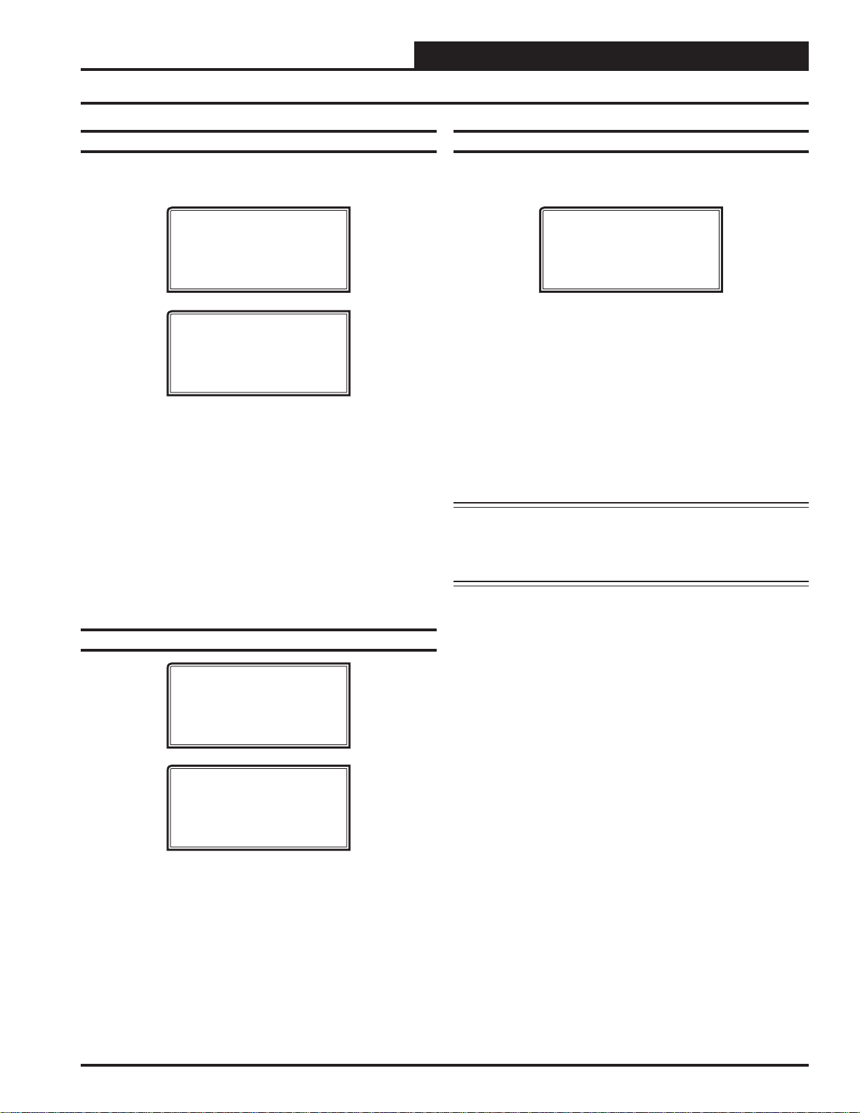
Confi guration Screen #1 - Sensor Scaling
VCC-X Cnfg ID #
Sensor Scaling
Fahrenheit
USE < or > TO CHANGE
NOTE: If the *00* remains, it indicates a communication
failure to the controller.
System Manager SD Instructions
From any Main screen, press <SETPOINTS>. The screen below
will appear because this option requires passcode clearance. Only a
Level 2 passcode can change setpoints.
THIS ACTION REQUIRES
PASSCODE CLEARANCE
Enter Passcode: XXXX
If the correct passcode was entered, the Unit Selection Screen will
be displayed.
Enter Unit Address
Then Press Enter
Selected Unit #_1
Press Down
Enter the correct unit ID number of the VCC-X Controller you
want to confi gure and then press <ENTER>. Once communication
is established, the *00* message will go away. Then
press <>.
Options are Fahrenheit or Celsius. If you make a change to this
screen, after you press <ENTER> to have the system accept the
change, you must return to the Unit Selection Screen to re-establish
communications with the Controller. Default is Fahrenheit.
Confi guration Screen #2 - RSM #1 & #2
Module Installed
VCC-X Cnfg ID #
RSM#1 Installed: NO
RSM#2 Installed: NO
USE < or > TO CHANGE
If you have a one RSMV Module installed, the 1st confi guration op-
tion should be confi gured as YES. If you have a 2nd RSMV Module
installed, the 2nd confi guration option should be confi gured as YES.
Default is NO.
VCC-X Operator Interface SD
25
Page 26
VCC-X CONFIGURATION
VCC-X Confi guration Screens
Zone
Zone
Confi guration Screen #3 - RSM #3 & #4
Modules Installed
VCC-X Cnfg ID #
RSM#3 Installed: NO
RSM#4 Installed: NO
USE < or > TO CHANGE
If you have a 3rd RSMV Module installed, the 1st confi guration op-
tion should be confi gured as YES. If you have a 4th RSMV Module
installed, the 2nd confi guration option should be confi gured as YES.
Default is NO.
Confi guration Screen #4 - EM1 Expansion
Module Installed
VCC-X Cnfg ID #
EM1 Installed: NO
USE < or > TO CHANGE
If you have Expansion Module EM1 installed, this confi guration
option should be confi gured as YES. Default is NO. If your unit
utilizes the following, an EM1 Module is required:
Modulating Chilled Water
Return Air Bypass Control
Title 24 Economizer Actuator Feedback
Confi guration Screen #5 - MHGRV-X &
MODGAS-X Installed
VCC-X Cnfg ID #
MHGRV Installed: NO
MODGS Installed: NO
USE < or > TO CHANGE
If you have an MHGRV-X Controller installed, the fi rst confi gura-
tion option should be confi gured as YES. If you have a MODGAS-
X Controller installed, the second confi guration option should be
confi gured as YES. Defaults are NO.
Confi guration Screen #6 - 12 Relay E-BUS
Expansion Module Installed
VCC-X Cnfg ID #
12RLY Installed: NO
USE < or > TO CHANGE
If you have a 12 Relay E-BUS Expansion Module installed, this
confi guration option should be confi gured as YES. Default is NO.
Confi guration Screen #7 - PREHEAT-X
Controller Installed
VCC-X Cnfg ID #
Preheat-X
Installed: NO
USE < or > TO CHANGE
If you have a PREHEAT-X Controller installed, this confi guration
option should be confi gured as YES. Default is NO.
Confi guration Screen #8 - HVA C Mode Enable Source
VCC-X Cnfg ID #
HVAC Source
Supply Air
USE < or > TO CHANGE
This selects which sensor will determine the mode of operation of
the unit and how it will operate. Default is Supply Air. Available
options are:
Supply Air—This is for a standard Cooling Only VAV
unit with optional Morning Warm Up. In the Occupied
Mode, the unit will be in the Cooling Mode controlling
to the Cooling Supply Air Setpoint.
Supply Air/Tempering—This selection is for VAV
“cooling only” applications where because of cold
outdoor temperatures, heat may need to be added in
order to maintain the “Cooling” Supply Air Setpoint.
This application requires Outdoor Air Enable Setpoints
to be confi gured in order to initiate Cooling and Heating
Modes. The Cooling and Heating Supply Air Setpoints
can then both be set to the same temperature (e.g. 55
º).
Outdoor Air—This is for a 100% OA Unit (MUA) using
the OA Temperature Sensor to determine the Heating,
Cooling, and Vent Modes of operation. Dehumidifi cation
utilizes an Outdoor Air Dewpoint Setpoint.
R eturn Air—Optional recirculating unit confi guration
using the Return Temperature Sensor to determine the
Heating, Cooling, and Vent Modes of operation.
Space Temperature—Typical recirculating unit using
a Space Temperature Sensor to determine the Heating,
Cooling, and Vent Modes of operation.
Space Temperature with High % OA CFM—If it is
preferable to use Space conditions (instead of Outside
Air) to control a 100% or high percentage outdoor air
unit, this option allows tempering of the outdoor air in
the Space Vent Mode of operation to prevent dumping of
hot or cold air into the space. See the Sequence of
Operations for details.
Single Zone VAV—Recirculating unit using the Space
Temperature Sensor to determine the mode of operation.
Heating and Cooling are controlled to a Leaving Air
Setpoint. Space Temperature resets the Supply Fan VFD
speed to maintain the Space Temperature. Modulating
Heating and Cooling must be used for this operation.
Can be confi gured for CAV Heating using staged Heat.
26
VCC-X Operator Interface SD
Page 27
VCC-X CONFIGURATION
VCC-X Confi guration Screens
Confi guration Screen #9 - HVAC Mode Set By
Remote Contact
VCC-X Cnfg ID #
HVAC Mode Set By
Remote Contact: NO
USE < or > TO CHANGE
This option allows separate 24 VAC wet contact closures on the
VCC-X to force the unit into Heating, Cooling, and Dehumidifi ca-
tion modes. If this option is selected, it applies to all three modes,
and all three modes will only be initiated by these contact closures.
See the VCC-X Remote Contact Control section of the Sequence
of Operations in the VCC-X Controller Technical Guide for more
details. Default is NO.
Confi guration Screen #10 - SAT Reset Source
VCC-X Cnfg ID #
SAT Reset Source
No Reset
USE < or > TO CHANGE
This confi guration option is not available if Single Zone VAV was
selected as the HVAC source. The Supply Air Setpoint can be “automatically” adjusted based on a selected reset source. This screen
allows you to choose this source.
selections are as follows:
Default is No Reset. The available
No Reset—No SAT Setpoint Reset will occur. The SAT
Setpoints remain fi xed.
Space Temperature—The SAT Setpoints will be
adjusted based on the Space Temperature.
Outdoor Temperature—The SAT Setpoints will be
adjusted based on the Outdoor Air Temperature.
Return Air Temperature—The SAT Setpoints will be
adjusted based on the Return Air Temperature.
F an VFD Signal—The SAT Setpoints will be adjusted
based on the VFD Signal. This is good for Adjusting the
Setpoints based on the building’s load by looking at the
VFD speed.
R emote Voltage—The SAT Setpoints will be
adjusted based on the Remote Supply Air Temperature
Voltage Reset Signal.
If the HVAC Source was set Single Zone VAV in Confi guration
Screen #8, then line 3 on this screen will read No SAT Rst Allowed
and the line 4 will be blank.
Confi guration Screen #11 - Reset Rate Interval
VCC-X Cnfg ID #
Reset Interval
Rate...: 30 s
[1 - 255 Seconds]
If you selected a Reset Source in Confi guration Screen #10, enter
a value in seconds between 1-255. This value determines how fast
the Supply Air T emperature Setpoint is adjusted as the Reset Source
changes. Default is 30 seconds.
Confi guration Screen #12 - Space Sensor Type
VCC-X Cnfg ID #
Space Sensor Type
NONE
USE < or > TO CHANGE
If this unit has a Space Sensor installed, select Analog if it is a
wired Thermistor temperature sensor. Select E-bus Space/RH if it
is a combination communicating temperature and humidity sensor.
Select Receive Broadcast if the Space Sensor is attached to a separate device that will broadcast the reading, e.g., GPC-XP Controller .
Select Remote Sensor if using a Sensor connected to a separate Unit
Controller on the same loop (sharing a sensor). You can select the
Unit Controller that will have the space sensor on Confi guration
Screen #13. Default is NONE.
Confi guration Screen #13 - Remote Space
Sensor Board Address
VCC-X Cnfg ID #
Remote Space Sensor
Board Address: 0
If using a Remote Space Sensor (must be chosen in Confi guration
Screen #12), enter the address of the board it is located on. This Unit
Controller has to be on the same loop as the Controller that will be
sharing the sensor.
Confi guration Screen #14 - Outdoor Sensor Type
VCC-X Cnfg ID #
Outdoor Sensor Type
NONE
USE < or > TO CHANGE
VCC-X Operator Interface SD
If this unit has an Outdoor Air Sensor installed, select Analog if it
is a wired Thermistor temperature sensor. Select E-bus OAT/RH
if it is a combination communicating temperature and humidity
sensor. Select Receive Broadcast if the Outdoor Sensor is attached
to a separate device that will broadcast the reading, e.g., GPC-XP
Controller. Default is NONE.
27
Page 28
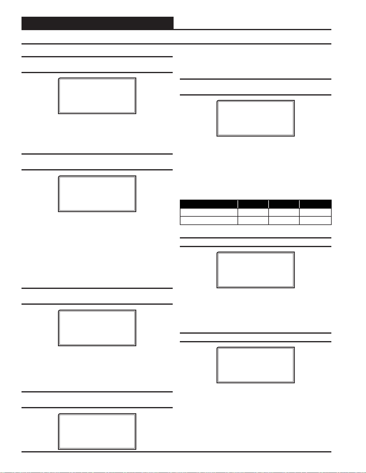
VCC-X CONFIGURATION
VCC-X Confi guration Screens
Zone
Zone
Confi guration Screen #15 - Return Sensor
Type
VCC-X Cnfg ID #
Return Sensor Type
NONE
USE < or > TO CHANGE
If this unit has a Return Air Sensor installed, select Analog if it is a
wired Thermistor temperature sensor. Select E-bus Return/RH if it
is a combination communicating temperature and humidity sensor.
Default is NONE.
Confi guration Screen #16 - Static Pressure
Control
VCC-X Cnfg ID #
Static Pr Control
Fan VFD
USE < or > TO CHANGE
Select what type of Duct Static Pressure is being controlled, if any.
Default is Fan VFD. The options are:
None— This unit is not controlling Duct Static Pressure.
Fan VFD—This unit has a Supply Fan VFD that
modulates to control the Duct Static Pressure or this is a
Single Zone VAV application.
Bypass Damper—This unit uses a Bypass Damper to
control the Duct Static Pressure.
This is the maximum amount that the Static Pressure Control output
can adjust to when it needs to. Default is 5 percent.
Confi guration Screen #19 - Fan Voltage
Output
VCC-X Cnfg ID #
Fan Voltage Output
Min Volts: 0.0VDC
Max Volts: 10.0VDC
Enter a value between 0.0 and 10.0 VDC for the main fan’ s minimum
and maximum output voltage. The Duct Static Pressure Output
Status Screen will display 0% to 100%, but the output will range
from the minimum value set on this screen to the maximum value
set on this screen.
The VCC-X will reverse the logic of the output signal when a Zoning
Bypass Damper is used. Defaults are 0 VDC Min and 10 VDC Max.
Description Minimum Default Maximum
Minimum Fan Voltage 0 0 10
Maximum Fan Voltage 0 10 10
Confi guration Screen #20 - Fan Cycle Mode
VCC-X Cnfg ID #
Fan Cycle Mode
NO
USE < or > TO CHANGE
Confi guration Screen #17 - Static/Fan Control
Rate
VCC-X Cnfg ID #
Static/Fan Control
Rate: 10s
[ 1 - 30 Seconds ]
This value determines the time interval between changes to the Supply Fan Speed or the Bypass Damper Position during Duct Static
Pressure Control. It also determines the time interval between
changes to the Fan Speed during Single Zone VAV Reset of the
Supply Fan VFD Speed. Default is 10 seconds.
Confi guration Screen #18 - Static Pressure
Control Rate Max Adjust
VCC-X Cnfg ID #
Static Pr. Control
Max Adjust: 5%
[ 1 - 30% ]
28
Select YES if you want the HVAC unit’s Supply Fan to only run dur-
ing Heating or Cooling Mode. If you want the HVAC unit’s Supply
Fan to run continuously while in the Occupied Mode, regardless of
the Heating or Cooling Mode,
select NO. Default is NO.
Confi guration Screen #21 - Fan Proving
VCC-X Cnfg ID #
Fan Proving
NO
USE < or > TO CHANGE
Select YES if the unit is equipped with a Proof of Flow Switch and
it is connected to the VCC-X. If selected as YES and the Proof of
Flow Switch is open, only the Supply Fan Relay will be active. If
any other relays such as Heating Stages or Cooling Stages are active, they will be deactivated when the Proof of Flow Switch input
is lost. Default is NO.
VCC-X Operator Interface SD
Page 29
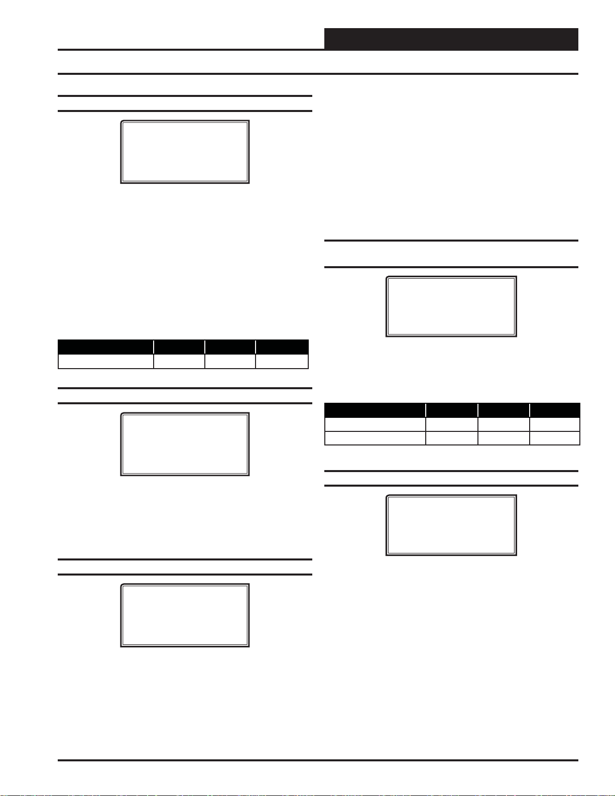
Confi guration Screen #22 - Fan Starting Delay
VCC-X Cnfg ID #
Fan Starting
Delay: -1s
[-1 = Unit Addr x 5]
VCC-X CONFIGURATION
VCC-X Confi guration Screens
Mod Heat Then Staged
st
form of Heat and Stage(s) of Heat as the 2nd form of
1
Heat.
Mod Gas Heat Only—Only Modulating Gas Heat
controlled by the AAON® MODGAS-X Controller.
Mod Gas Then Staged—ModGas Heat as the 1
of Heat and Stage(s) of Heat as the 2nd form of Heat.
—Fully modulating Heat as the
st
form
Enter the number of seconds you want the fan to delay starting. This is
the Supply Fan Starting Delay initiated whenever the VCC-X initiates
Supply Fan operation upon going occupied or after power-up. This is
useful when you are using multiple VCC-X-controlled HVAC units and
want to be sure that all the units do not start at exactly the same time
when the Occupied schedule occurs. Each VCC-X should be set with
staggered Fan Starting Delay Setpoint values. When the -1 value is used,
it multiplies each VCC-X Controller’s address by 5 and uses this value
in seconds as the Fan Starting Delay. This provides a staggered start for
each VCC-X Controller on the system without having to individually set
each VCC-X Controller for its own time delay.
should be set to a minimum of 60 seconds to let the OA Damper
open.
Default is -1 second.
Description Minimum Default Maximum
Fan Start Delay Timer -1 Sec -1 Sec 240 Sec
For an MUA unit, this
Confi guration Screen #23 - Purge Mode Delay
VCC-X Cnfg ID #
Purge Mode
Delay: 10s
[ 0 - 900 Seconds ]
Enter the number of seconds you want the unit to stay in Purge Mode
before going into Occupied Mode. In Purge Mode, the fan runs with the
Economizer closed and all Cooling and Heating is de-energized.
MUA unit, this should be set to 0 seconds to prevent a Pur ge Mode
(which is a damper closed operation).
Default is 10 seconds.
For an
See the VCC-X Controller Technical Guide for a more detailed descrip-
tion of these operations.
Confi guration Screen #25 - Modulating Heat
Output Signal
VCC-X Cnfg ID #
Mod Heat Volt Output
Min Pos Volts: 0.0
Max Pos Volts: 10.0
Enter a value between 0.0 and 10.0 VDC for the Modulating Heat
minimum and maximum output voltage. When performing reverse
acting heating, the minimum position volts will be the highest value.
Defaults are 0 VDC Min and 10 VDC Max.
Description Minimum Default Maximum
Minimum Position Volts 0 0 10
Maximum Position Volts 0 10 10
Confi guration Screen #26 - Cool Type
VCC-X Cnfg ID #
Cool Type
Refrigeration Module
USE < or > TO CHANGE
Confi guration Screen #24 - Heat Type
VCC-X Cnfg ID #
Heat Type
No Heat
USE < or > TO CHANGE
Default is No Heat. Available options are:
No Heat
Staged Only
Mod Heat Only
Heat which would be Modulating Hot Water or Steam Heat
or Modulating SCR Electric Heat. Does not include
Modulating Gas using the AAON
Controller.
—The unit has no Heat.
—On/Off Hot Water or fi xed stage(s) of Heat.
—Only fully modulating forms of
®
MODGAS-X
VCC-X Operator Interface SD
Default is Refrigeration Module. Available options are:
Refrigeration Module—A Refrigeration Module is
installed and confi gured.
Staged Only—On/Off Chilled Water or fi xed stage(s)
DX Cooling only and no Compressor Dehumidifi cation.
Mod Only— Modulating Chilled Water
29
Page 30
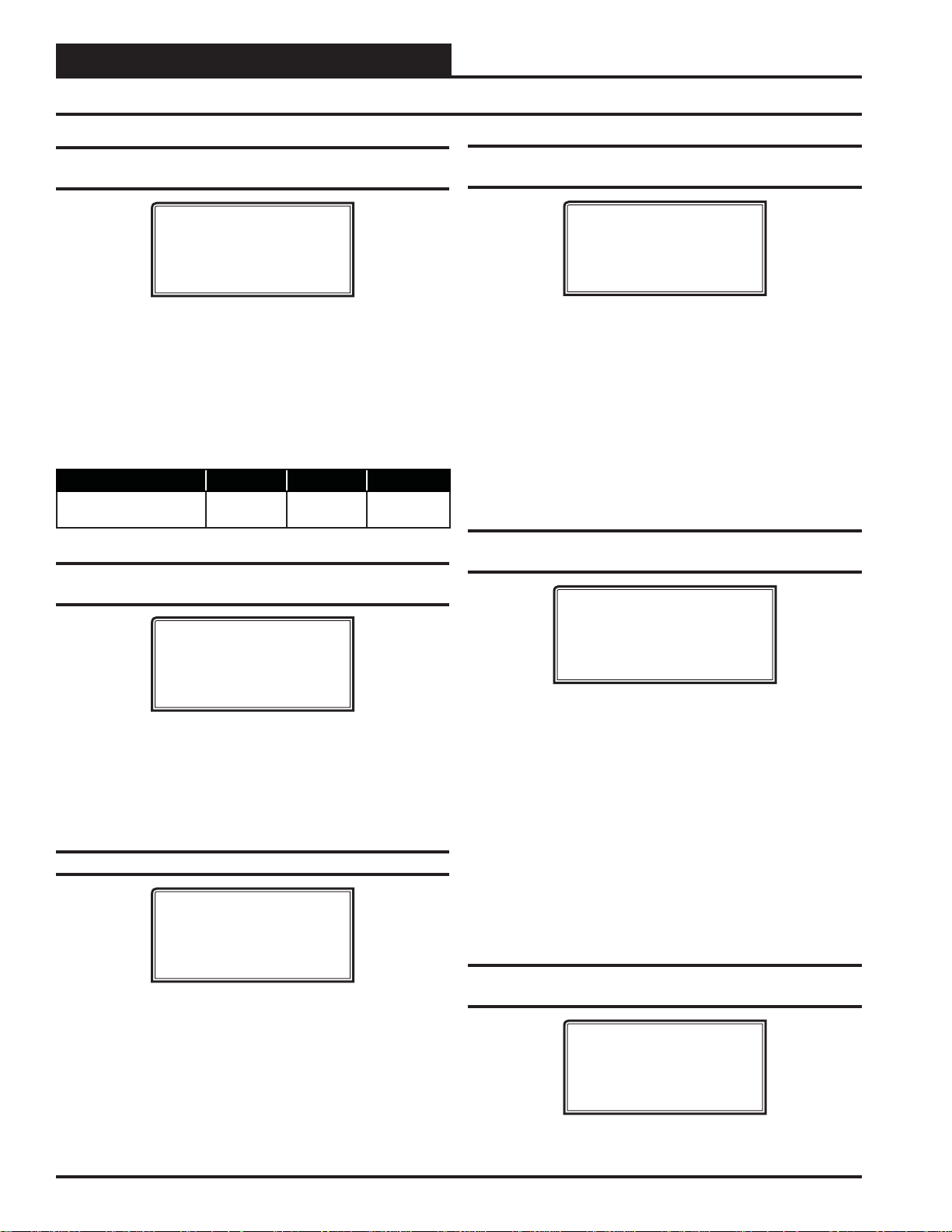
VCC-X CONFIGURATION
VCC-X Confi guration Screens
Zone
Zone
Confi guration Screen #27 - Mechanical Heat/
Cool Alarm Delay
VCC-X Cnfg ID #
Mech Heat/Cool
Alarm Delay: 15Min
Enter a time delay between 0-240 minutes for a delay in the time that
it takes an alarm to be generated.
initiated and staging is activated, if the Supply Air T emperature does
not rise or fall 5°F within this time period, a Mechanical Heating
or Cooling failure alarm will be generated. The Alarm is for Status
Reporting only. The HVAC unit will continue to run. This alarm
does not apply if Modulating Cooling or Heating are confi gured.
Default is 15 minutes.
Description Minimum Default Maximum
Mechanical Heat/Cool
Failure Alarm Delay
When Heating or Cooling Mode is
0 Min 15 Min 240 Min
Confi guration Screen #28 - Economizer Control
Type
VCC-X Cnfg ID #
Econo Control Type
No Economizer
USE < or > TO CHANGE
Default is No Economizer. Available options are:
No Economizer
Standard Economizer
IAQ Economiz er (Economizer with CO
Confi guration Screen #29 - Title 24 Economizer
VCC-X Cnfg ID #
Title 24
Economizer: NO
USE < or > TO CHANGE
If this unit has Title 24 Economizer operation, this option should be
confi gured as YES. Default is NO.
Override)
2
Confi guration Screen #30 - Economizer in
Unoccupied Mode
VCC-X Cnfg ID #
Econo Control In
Unoc Mode: NO
USE < or > TO CHANGE
Select YES for the Economizer to operate in the Unoccupied Cooling
Mode. Default is NO.
NO—You want the Economizer to always remain fully
Closed in the Unoccupied mode.
YES—You want to use the Economizer as necessary
during Unoccupied Night Setback cooling calls. It will
be utilized just as it would be in the Occupied mode with
the same outdoor enable temperature. If not being used
for Night Setback Free Cooling, the Economizer will be
closed.
Confi guration Screen #31 - Economizer Enable
Source
VCC-X Cnfg ID #
Econo Enable Source
Drybulb
USE < or > TO CHANGE
This confi guration option is available if the unit was confi gured for
Economizer Control.
Default is Drybulb. Available options are:
Drybulb—If the Outdoor Air Drybulb temperature is
below the Economizer Enable Setpoint, the Economizer
can be used as the fi rst stage of cooling.
W etbulb (O A RH Sensor needed)—If the Outside Air
Wetbulb temperature is below the Economizer Enable
Setpoint, the Economizer can be used as the fi rst stage of
cooling.
Dewpoint (O A RH Sensor needed)—If the Outdoor
Air Dewpoint temperature is below the Economizer
Enable Setpoint, the Economizer can be used as the fi rst
stage of cooling.
Confi guration Screen #32 - Economizer Control
Loop Rate
VCC-X Cnfg ID #
Economizer Control
Rate: 10 s
[ 1 - 30 Seconds ]
30
Enter a number between 1 and 30 seconds. This is the time period
between changes to the Economizer position. Default is 10 seconds.
VCC-X Operator Interface SD
Page 31
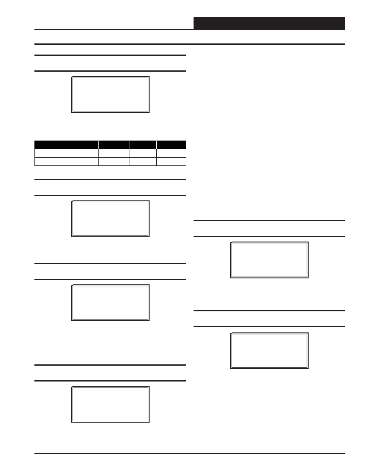
VCC-X CONFIGURATION
VCC-X Confi guration Screens
Confi guration Screen #33 - Economizer
Voltage Output
VCC-X Cnfg ID #
Econo Voltage Output
Min Volts: 2.0VDC
Max Volts: 10.0VDC
Enter a value between 0.0 and 10.0 VDC for the Economizer mini-
mum and maximum output voltage. Defaults are 2 VDC Min and
10 VDC Max.
Description Minimum Default Maximum
Min Economizer Voltage 0 2 10
Max Economizer Voltage 0 10 10
Confi guration Screen #34 - CO2 Sensor
Installed
VCC-X Cnfg ID #
CO2 Sensor Installed
NO
USE < or > TO CHANGE
On/Off Exh Relay—If an On/Off Exhaust Fan is being
used, select this option and confi gure a relay output as
Exhaust Fan. If the building pressure rises above
setpoint, this relay will energize. This is Direct-Acting
control.
Modula ting Exh—If the building pressure rises above
setpoint, a modulating signal will be used to control an
exhaust fan VFD or a modulating damper to maintain
setpoint. A relay confi gured as Exhaust Fan can be used
to enable this device so that the modulating signal can
control it. This is Direct Acting control.
OA Damper—Select if reverse acting Building Pressure
Control using the Outdoor Air Damper is required. If
the building pressure falls below setpoint, the OA
Damper (Economizer) signal will be used to modulate
the OA Damper to maintain setpoint. This is Reverse
Acting control.
Supply Fan—Contact WattMaster Factory regarding
this reverse acting Building Control option. This should
not be used in most applications. This is Reverse Acting
control.
Confi guration Screen #37 - Building Pressure
Control Rate
Select YES if you have a CO
Sensor installed. Default is NO.
2
Confi guration Screen #35 - Building Pressure
Sensor Installed
VCC-X Cnfg ID #
Building Pr. Sensor
Installed
None
If this unit has a Building Pressure Sensor installed, select Analog if
it is a wired sensor. Select Receive Broadcast if the Building Pressure Sensor is attached to a separate device that will broadcast the
reading, e.g., GPC-XP Controller. Default is None.
Confi guration Screen #36 - Building Pressure
Control
VCC-X Cnfg ID #
Building Pr. Control
None
USE < or > TO CHANGE
VCC-X Cnfg ID #
Building Pr. Control
Rate: 10 Sec
[ 1 - 30 Seconds ]
Default is 10 seconds. The Building Pressure Control Rate is the
time period between changes to the Building Pressure Control signal.
Confi guration Screen #38 - Building Pressure
Control Max Adjust
VCC-X Cnfg ID #
Building Pr. Control
Max Adjust: 5%
[ 1 - 30% ]
This is the maximum amount that the Building Pressure Control
output can adjust to when it needs to. Default is 5 percent.
Default is None. Available options are:
None—No Building Pressure Control by this controller.
VCC-X Operator Interface SD
31
Page 32

VCC-X CONFIGURATION
VCC-X Confi guration Screens
Zone
Zone
Confi guration Screen #39 - Exhaust Fan
Output
VCC-X Cnfg ID #
Exh Fan Volts
Min Volts: 0.0VDC
Max Volts: 10.0VDC
This confi guration option is available if Modulating Building Pres-
sure Control was confi gured on a previous screen. The following
will set the output voltage range for both Direct and Reverse Acting
Building Pressure Control. Defaults are 0 VDC Min Volts and 10
VDC Max Volts. Available options are:
Min Volts—Voltage at which the signal to exhaust fan,
exhaust damper, or OA damper will be at 0% for either
Direct or Reverse Acting Building Pressure control.
Max Volts—Voltage at which the signal to exhaust fan,
exhaust damper, or OA damper will be at 100% for
either Direct or Reverse Acting Building Pressure
control.
Description Minimum Default Maximum
Minimum Position Volts 0.0 0.0 10.0
Maximum Position Volts 0.0 10.0 10.0
All Modes Anytime—This is Occupied and
Unoccupied Dehumidifi cation Priority. The unit can
enter Dehumidifi cation during Cooling, Heating, or Vent
Modes while in Occupied or Unoccupied operation.
For units controlled by space humidity sensors, Dehumidifi cation
is initiated based on an Indoor Humidity Setpoint. For 100% OA
units (MUA), Occupied Dehumidifi cation is initiated based on
an Outdoor Air Dewpoint Setpoint. For MUA units, Unoccupied
Dehumidifi cation can only occur if the unit is confi gured for Night
Setback recirculating operation and has a Space Humidity sensor
and a Space Humidity Setpoint.
Confi guration Screen #41 - Humidity Control
Sensor Type
VCC-X Cnfg ID #
Humidity Control
Sensor: Space
USE < or > TO CHANGE
Select Space, Return, or Outdoor if an E-BUS Humidity Sensor is
installed. Default is Space.
Confi guration Screen #42 - Reheat Type
Confi guration Screen #40 - Dehumidifi cation
Control
VCC-X Cnfg ID #
Dehum. Control:
None
USE < or > TO CHANGE
If using Dehumidifi cation choose the appropriate Dehumidifi cation
option. Default is None. Available options are:
None—The unit does not have a Dehumidifi cation
Mode.
Only Occupied Vent—The unit can only enter
Dehumidifi cation during the Occupied Vent Mode (when
there is no call for Cooling or Heating).
Only Vent Anytime—The unit can only enter
Dehumidifi cation during the Vent Mode (when there
is no call for Cooling or Heating) in both the Occupied
and Unoccupied operation.
All Modes Occupied—This is Occupied Mode
Dehumidifi cation Priority. The unit can enter
Dehumidifi cation during Cooling, Heating, or Vent
Modes, but only while in Occupied operation.
VCC-X Cnfg ID #
Reheat Control
None
USE < or > TO CHANGE
This confi guration option is available if Dehumidifi cation has been
confi gured. If you need Reheat in the Dehumidifi cation mode, this
screen allows you to confi gure what kind of reheat will be used.
The output(s) will be staged or modulated to maintain the Active
Supply Air Setpoint. Default is None.
will be used during dehumidifi cation.
Select the type of reheat that
None—No reheat.
On/Off HGR Relay—Single On/Off Reheat stage
(Reheat Relay).
Mod HGR—Modulating Hot Gas Reheat (MHGR)
Unit Heat—Using the unit’s heat as Reheat when Hot
Gas Reheat is not available.
Mod HGR + Unit Heat—Using MHGR as the 1
form of Reheat, supplemented by unit Heat if necessary.
st
On/Off HGR + Unit Heat—Using “Reheat Relay”
st
stage as the 1
Heat if necessary.
form of Reheat, supplemented by unit
32
VCC-X Operator Interface SD
Page 33

VCC-X CONFIGURATION
VCC-X Confi guration Screens
Confi guration Screen #43 - Type of Airfl ow
Station
VCC-X Cnfg ID #
Airflow
Station: Paragon
USE < or > TO CHANGE
Select the type of Airfl ow Monitoring Station you are using, if any .
Selections are Ebtron or Paragon. Default is Paragon.
Confi guration Screen #44 - Monitor Outdoor
Air Airfl ow
VCC-X Cnfg ID #
Monitor OA Airflow
NO
USE < or > TO CHANGE
Select YES if you have an Airfl ow Monitoring station measuring the
CFM of the Outdoor Air airfl ow stream of this unit. Default is NO.
Confi guration Screen #45 - Control Outdoor
Air CFM
VCC-X Cnfg ID #
Control Outdoor Air
CFM: NO
USE < or > TO CHANGE
Confi guration Screen #47 - Monitor Supply Air
Airfl ow
VCC-X Cnfg ID #
Monitor SA Airflow
NO
USE < or > TO CHANGE
Select YES if you have an Airfl ow Monitoring station measuring the
CFM of the Supply Air airfl ow stream of this unit. Default is NO.
Confi guration Screen #48 - Supply Airfl ow
Duct Size
VCC-X Cnfg ID #
Supply Airflow Duct
Size: 0.00
[ In Square Feet ]
For the controller to properly calculate the Supply Air CFM, you need
to enter the area in square feet of the Supply Air duct/damper . When
measuring the Supply Air duct damper area, be sure to measure the
inside dimensions of the damper. The duct size needs to be accurate
to two decimal places. The more accurate the measurements, the
more accurate the CFM reading will be. Default is 0.
Description Minimum Default Maximum
Supply Air Airfl ow Duct Size 0 0 200.00
Select YES if you have an Airfl ow Monitoring station and are
controlling the Outdoor Air Damper to an airfl ow (CFM) Setpoint.
Default is NO.
Confi guration Screen #46 - Outdoor Airfl ow
Duct Size
VCC-X Cnfg ID #
Outdoor Airflow Duct
Size: 0.00
[ In Square Feet ]
For the controller to properly calculate the Outdoor Air CFM, you
need to
enter the area in square feet of the Outdoor Air duct/damper .
When measuring the Outdoor Air duct damper area, be sure to measure the inside dimensions of the damper. The duct size needs to be
accurate to two decimal places. The more accurate the measurements,
the more accurate the CFM reading will be. Default is 0.
Description Minimum Default Maximum
Outdoor Air Airfl ow Duct Size 0 0 200.00
VCC-X Operator Interface SD
Confi guration Screen #49 - Monitor Return Air
Airfl ow
VCC-X Cnfg ID #
Monitor RA Airflow
NO
USE < or > TO CHANGE
Select YES if you have an Airfl ow Monitoring station measuring the
CFM of the Return Air airfl ow stream of this unit. Default is NO.
33
Page 34

VCC-X CONFIGURATION
VCC-X Confi guration Screens
Zone
Zone
Confi guration Screen #50 - Return Airfl ow
Duct Size
VCC-X Cnfg ID #
Return Airflow Duct
Size: 0.00
[ In Square Feet ]
For the controller to properly calculate the Return Air CFM, you need
to enter the area in square feet of the Return Air duct/damper . When
measuring the Return Air duct damper area, be sure to measure the
inside dimensions of the damper. The duct size needs to be accurate
to two decimal places. The more accurate the measurements, the
more accurate the CFM reading will be. Default is 0.
Description Minimum Default Maximum
Return Air Airfl ow Duct
Size
0 0 200.00
Confi guration Screen #51 - Monitor Exhaust
Airfl ow
VCC-X Cnfg ID #
Monitor Exh Airflow
NO
USE < or > TO CHANGE
Select YES if you have an Airfl ow Monitoring station measuring the
CFM of the Exhaust Air airfl ow stream of this unit. Default is NO.
Confi guration Screen #52 - Exhaust Airfl ow
Duct Size
Confi guration Screen #53 - Morning Warm Up
VCC-X Cnfg ID #
Morning Warm Up
None
USE < or > TO CHANGE
You can choose between the following Morning Warm Up options.
Default is None. Available options are:
None— There is no Morning Warm Up required.
Stand Alone—The VCC-X Controller is not
communicating to Orion VAV Box controls, but a
Morning Warm Up Relay can be confi gured to signal
boxes by others to open.
Bcast Fixed to Boxes—The VCC-X Controller is
communicating to Orion VAV Boxes and will broadcast
a command to the boxes to go to a Fixed Percentage
Position or Airfl ow while in Morning Warm Up. This
fi xed position is confi gured in the VAV Box Controller.
Bcast Max to Boxes—The VCC-X Controller is
communicating to Orion VAV Boxes and will broadcast
a command to the boxes to go to a Maximum Percentage
Position or Airfl ow while in Morning Warm Up. This
maximum position is confi gured in the VAV Box
Controller.
Confi guration Screen #54 - AHU Uses
Schedule Number
VCC-X Cnfg ID #
AHU Uses Schedule
Number: 0
[‘0’ For Internal]
VCC-X Cnfg ID #
Exhaust Airflow Duct
Size: 0.00
[ In Square Feet ]
For the controller to properly calculate the Exhaust Air CFM, you
need to enter the inside area in square feet of the Exhaust Air duct/
damper. When measuring the Exhaust Air damper area, be sure to
measure the inside dimensions of the damper. The duct size needs to
be accurate to two decimal places. The more accurate the measurements, the more accurate the CFM reading will be. Default is 0.
Description Minimum Default Maximum
Exhaust Airfl ow Duct Size 0 0 200.00
34
The VCC-X has an internal schedule. If you want the VCC-X to use
its own internal schedule, enter <0> for Internal.
External Schedules are available by using one of the GPC-X family
of General Purpose Controllers. Depending on which generation of
GPC-X Controller you have, you may have up to 5 or up to 8 schedules available to use. T o use the schedules on one of these controllers,
enter the number of the schedule on that controller (either 1 through
5 or 1 through 8) you will be using. Default is 0.
Description Minimum Default Maximum
AHU Uses Schedule 0 0 8
VCC-X Operator Interface SD
Page 35

VCC-X CONFIGURATION
VCC-X Confi guration Screens
Confi guration Screen #55 - Daylight Savings
Adjustment
VCC-X Cnfg ID #
Daylight Adjustment
Start Date: 0
Stop Date: 0
If you are in a time zone that does not have daylight savings time or
do not want to use this feature, leave these fi elds blank. Otherwise,
enter the starting date for Daylight Savings time in the Start Date
fi eld and the ending date in the Stop Date fi eld. For example, March
11 = 311 (DDMM). Default is 0000.
Description Minimum Default Maximum
Start Date 0 0 1231
Stop Date 0 0 1231
NOTE: The U.S. government has the authority to determine
the switch-over dates each year. Currently, the time
changes the second Sunday in March and then
switches back the fi rst Sunday in November.
Confi guration Screen #58 - Dirty Filter
VCC-X Cnfg ID #
Dirty Filter
NO
USE < or > TO CHANGE
Select YES if a Dirty Filter switch is connected to the Dirty Filter
binary input. If the Dirty Filter input is active, an alarm will be
generated. Default is NO.
Confi guration Screen #59 - Broadcast OA Temp
VCC-X Cnfg ID #
Broadcast OA Temp
NO
USE < or > TO CHANGE
The VCC-X can broadcast its Outdoor Air Temperature Reading to
other HV AC units if they are not equipped with their own Outdoor Air
Temperature sensors. A network communications device (MiniLink
PD or CommLink) is needed in order for this feature to operate. Select
YES for Broadcast Outdoor Temperature. Default is NO.
Confi guration Screen #56 - Trend Log Rate
VCC-X Cnfg ID #
Trend Log
Rate: 15Min
[ 1 - 120 Minutes ]
An internal Trend Log is constantly updated at a rate equal to this
value. Trend Logs can only be accessed with Prism 2 software.
Default is 15 minutes.
Confi guration Screen #57 - Emergency
Shutdown
VCC-X Cnfg ID #
Emergency Shutdown
NO
USE < or > TO CHANGE
Select YES if a Smoke Detector/Firestat or other Emergency Shut-
down input is connected to the Emergency Shutdown binary input.
If a Shutdown condition occurs and the 24V signal is removed from
this input, the Supply Fan and Heating and Cooling Relay Outputs
will be de-energized and an alarm will be generated. Default is NO.
Confi guration Screen #60 - Broadcast OA RH
VCC-X Cnfg ID #
Broadcast OA RH
NO
USE < or > TO CHANGE
The VCC-X can broadcast its Outdoor Air Humidity Reading to
other HVAC units if they are not equipped with their own Outdoor
Air RH sensors. A network communications device (MiniLink PD
or CommLink) is needed in order for this feature to operate.
YES for Broadcast Outdoor RH. Default is NO.
Select
Confi guration Screen #61 - Broadcast Building
Pressure
VCC-X Cnfg ID #
Broadcast Build. Pr.
NO
USE < or > TO CHANGE
The VCC-X can broadcast Building Pressure from this unit to any
other unit requiring this value.
Pressure. Default is NO.
Select YES for Broadcast Building
VCC-X Operator Interface SD
35
Page 36

VCC-X CONFIGURATION
VCC-X Confi guration Screens
Zone
Zone
Confi guration Screen #62 - Broadcast to Boxes
VCC-X Cnfg ID #
Broadcast to Boxes
NO
USE < or > TO CHANGE
The VCC-X can broadcast all applicable information and commands
to the VA V Boxes. Select YES for Broadcast to Boxes. Default is NO.
Confi guration Screen #63- #66 - Cool/Heat
Stage Delays
VCC-X Cnfg ID #
Cool Stage Delays
Stage Up: 3 Min
Stage Down: 1 Min
VCC-X Cnfg ID #
Cool Stage Delays
Min Run: 5 Min
Min Off: 3 Min
Confi guration Screen #67 - Heat/Cool
Changeover Delay
VCC-X Cnfg ID #
Heat Cool Changeover
Delay: 5Min
[ 0 - 20 Minutes ]
Enter the time in minutes for the time delay when the unit changes
over from a call to heating to a call to cooling and vice versa. Default is 5 minutes.
Confi guration Screen #68 - Return Air Bypass
Control
VCC-X Cnfg ID #
Return Air Bypass
Control: NO
USE < or > TO CHANGE
Select Yes if your HV AC unit requires Return Air Bypass Control for
Dehumidifi cation Reheat. Default is NO. You must have the EM1
Expansion Module installed and confi gured for this feature.
VCC-X Cnfg ID #
Heat Stage Delays
Stage Up: 3 Min
Stage Down: 1 Min
VCC-X Cnfg ID #
Heat Stage Delays
Min Run: 5 Min
Min Off: 1 Min
Both the Heating Stages and the DX Cooling Stages utilize Staging
Up and Down Delay Periods between stages and Minimum Run
Times and Off T imes.
See the
these Delays and Run Times are used.
VCC-X Controller Technical Guide for information on how
Description Minimum Default Maximum
Cooling Stage Up 3 Min 3 Min 15 Min
Cooling Stage Down 1 Min 1 Min 15 Min
Cooling Min Run Time 5 Min 5 Min 15 Min
Cooling Min Off Time 3 Min 3 Min 15 Min
Heating Stage Up 3 Min 3 Min 15 Min
Heating Stage Down 1 Min 1 Min 15 Min
Heating Min Run Time 2 Min 5 Min 15 Min
Heating Min Off Time 1 Min 1 Min 15 Min
Confi guration Screen #69 - Morning
Cool-Down Type
VCC-X Cnfg ID #
Morning Cool-Down
None
USE < or > TO CHANGE
Y ou can choose between the following Morning Cool-Down options.
Default is None. Available options are:
None—There is no Cool-Down required.
Stand Alone—The VCC-X Controller is not
communicating to Orion VAV Box controls, but a
Cool-Down Relay can be confi gured to signal boxes by
others to open.
Bcast Fixed to Boxes—The VCC-X Controller is
communicating to Orion VAV Boxes and will broadcast
a command to the boxes to go to a Fixed Percentage
Position or Airfl ow while in Cool-Down. This fi xed
position is confi gured in the VAV Box Controller.
Bcast Max to Boxes—The VCC-X Controller is
communicating to Orion VAV Boxes and will broadcast
a command to the boxes to go to a Maximum Percentage
Position or Airfl ow while in Cool-Down. This maximum
position is confi gured in the VAV Box Controller.
36
VCC-X Operator Interface SD
Page 37

VCC-X CONFIGURATION
VCC-X Confi guration Screens
Confi guration Screens #70-76 - VCC-X Relay
Confi guration Screens
VCC-X Cnfg ID #
On-Board Relay (2-8)
Not Used
USE < or > TO CHANGE
Relay #1 is not confi gurable as it is reserved for the Supply Air Fan.
Relays #2-#8 are confi gurable for the following options (See Table
5, page 38 for Relay descriptions):
• Not Used (Default) • Cool Stage
• Heat Stage • Mod Heat Enable
• Mod Cool Enable • Warmup / Cooldown
• ReHeat • PreHeat
• Low Ambient • Exhaust Fan
• Economizer • Heat Wheel
• Occupied Mode • Override Mode
• Alarm Active
• Low Ambient • Exhaust Fan
• Economizer • Heat Wheel
• Occupied Mode • Override Mode
• Alarm Active
Relays #1 through #5 can be individually confi gured. Only forms of
Heating and Cooling can be confi gured with multiple relays for
staging. If any other option is selected more than once, it will simply
activate redundant relays, but no multiple staging will occur. Default
is Not Used.
Confi guration Screens #82-93 - E-BUS
12 Relay Confi guration Screens
VCC-X Cnfg ID #
12 Rly Bd Relay (1-12)
Not Used
USE < or > TO CHANGE
The E-BUS 12 Relay Expansion Board Relays #1-#12 are confi gu-
rable for the following options (See Table 5, page 38 for Relay
descriptions):
Relays #2 through #8 can be individually confi gured. Only forms
of Heating and Cooling can be confi gured with multiple relays for
staging. If any other option is selected more than once, it will simply activate redundant relays, but no multiple staging will occur.
Default is Not Used.
Confi guration Screens #77-81 - EM1 Relay
Confi guration Screens
VCC-X Cnfg ID #
EM1 Relay (1-5)
Not Used
USE < or > TO CHANGE
EM1 Relays #1-#5 are confi gurable for the following options (See
Table 5, page 38 for Relay descriptions):
• Not Used (Default) • Cool Stage
• Heat Stage • Mod Heat Enable
• Mod Cool Enable • Warmup / Cooldown
• Not Used (Default) • Cool Stage
• Heat Stage • Mod Heat Enable
• Mod Cool Enable • Warmup / Cooldown
• ReHeat • PreHeat
• Low Ambient • Exhaust Fan
• Economizer • Heat Wheel
• Occupied Mode • Override Mode
• Alarm Active
Relays #1 through #12 can be individually confi gured. Only forms
of Heating and Cooling can be confi gured with multiple relays for
staging. If any other option is selected more than once, it will simply activate redundant relays, but no multiple staging will occur.
Default is Not Used.
• ReHeat • PreHeat
VCC-X Operator Interface SD
37
Page 38

VCC-X CONFIGURATION
VCC-X Confi guration Screens
No. Relay Description Details
1
Cooling Stage
2
Heating Stage
3
Mod Heat Enable
4
Mod Cool Enable
Morning Warm-Up/
5
Cool-Down (VAV Boxes)
6
Reheat
7
Pre-Heat
8
Low Ambient
9
Exhaust Fan
Economizer Active
10
11
Heat Wheel
12
Occupied Active
13
Override Active
14
Alarm Active
Confi gured for each fi xed stage of cooling (except heat pump compressor).
Confi gured for each fi xed stage of heating.
Confi gure if a 0-10 VDC Modulating Heat source needs a relay to enable it.
Confi gure if a 0-10 VDC Modulating Cool source needs a relay to enable it.
Confi gure (1) Relay for Morning Warm-Up/Cool-Down when Non-Orion VAV/Zone Controllers are
used.
Confi gure (1) Relay for On/Off Reheat when used.
Confi gure for Pre-Heat operation.
Confi gure for Low Ambient operation.
Confi gure (1) Relay for enabling exhaust fan when Building Pressure Control is used.
If confi gured, this relay will energize if unit is in Economizer mode and the damper has moved 5%
above its Economizer Minimum Setpoint position.
Confi gure (1) Relay that turns heat wheel on when in occupied operation and turns heat wheel off
when in Economizer Mode.
If confi gured, this relay will energize whenever the unit is in the Occupied Mode.
If confi gured, this relay will energize anytime the space sensor Push-button override is active.
If confi gured, this relay will energize anytime a VCC-X alarm is active.
Zone
Zone
Table 5: User-Confi gurable Relay Outputs
38
VCC-X Operator Interface SD
Page 39

VCC-X CONFIGURATION
VCC-X Setpoint Screens
Setpoint Screen Index
The available Setpoint Screens for the VCC-X Controller are listed
on the next few pages by sequential screen number. When each
VCC-X Controller is confi gured for the fi rst time, it is best to start
with screen #1 and proceed to each Setpoint Screen in numerical
order until you have viewed all available Setpoint Screens. This
ensures that you have seen all of the available VCC-X Controller
Setpoint possibilities and have the opportunity to change or accept
the defaults for each screen. Once the unit Setpoints are confi gured
and you decide to change one of the screen options, it is helpful to
know what screen number contains the confi guration you wish to
change. With this in mind, the following is a list of all the VCC-X
Setpoint Screens in numerical order with a brief listing of the Setpoint
feature available on each screen:
Screen #1 Occupied HVAC Cool/Heat
Screen #2 Hood On HVAC Setpoints
Screen #3 Unoccupied Offsets
Screen #4 Mode Deadband Setpoint
Screen #5 Space Sensor Slide Adjust
Screen #6 Space Sensor Push-Button Override Duration
Screen #7 Controlling Sensor High Alarm Offset
Screen #8 Controlling Sensor Low Alarm Offset
Screen #9 Outdoor Dewpoint Setpoint
Screen #10 Indoor RH Setpoints
Screen #11 Coil (Saturation) Temperature Setpoints
Screen #12 Static Pressure Setpoint and Deadband
Screen #13 VFD Speed Limits - Min Cool/Min Vent
Screen #14 VFD Speed Limits - Min/Max Heat
Screen #15 Supply Air Cooling Setpoint and High Reset
Limit
Screen #16 Cool Reset Source Setpoints -
High Reset/Low Reset
Screen #17 Supply Air Heating Setpoint and
High Reset Limit
Screen #18 Heat Reset Source Setpoints -
High Reset/Low Reset
Screen #19 Stage Off Window Cooling/Heating
Screen #20 Mod Heat Proportional Window and Time
Period
Screen #21 Mod Cool Proportional Window and Time
Period
Screen #22 Head Pressure Setpoints - Cooling and Reheat
Screen #23 Economizer Enable Setpoint
Screen #24 Economizer Minimum Damper Position
Screen #25 Maximum Economizer Position in Heat Mode
Screen #26 Min Outdoor Airfl ow Setpoint and Deadband
Screen #27 Economizer Maximum Position in High CO
Screen #28 CO2 Setpoints Min/Max
Screen #29 CO
Screen #30 Building Pressure Setpoint and Deadband
Screen #31 OAT Lockouts - Comp Cool/Comp Heat
Screen #32 OAT Lockouts Heat
Screen #33 Supply Air Cutoffs - Cooling/Heating
Screen #34 Mod Heat Output Position in Off Mode
Screen #35 Preheat Relay Setpoint
Screen #36 Low Ambient Setpoint
Screen #37 Heat Wheel Defrost Temperature Setpoint
Screen #38 Morning Warm Up Max Length and Target
Temp
Screen #39 SZ VAV Integral Constant
Screen #40 Return Air Bypass Damper Factor Setpoint
Screen #41 Warm-Up Supply Air Temperature Setpoint
Screen #42 Cool-Down Supply Air Temperature Setpoint
Screen #43 Preheat-X Setpoints - Cool & Heat Mode
Screen #44 Preheat-X Setpoint - Vent Mode
Screen #45 Superheat Setpoint
Screen #46 Space Sensor Calibration - Current and Offset
Screen #47 RAT Sensor Calibration - Current and Offset
Screen #48 SAT Sensor Calibration - Current and Offset
Screen #49 OAT Sensor Calibration - Current and Offset
Screen #50 CO
Altitude Setpoint
2
Sensor Calibration - Current and Offset
2
2
VCC-X Operator Interface SD
39
Page 40

VCC-X SETPOINTS
VCC-X Setpoint Screens
Setpoints - General Procedures
Modular Service Tool Instructions
From any menu screen, press <SETPOINTS>. The Unit Selection
Screen, shown below,
ID number.
Enter the correct unit ID number of the VCC-X Controller you want
to change Setpoints for and press <ENTER>. Once communication
is established, the *00* message will go away. Then
will then see Setpoint Screen #1. Press
data and
press <> to scroll through the screens.
NOTE: If the *00* remains, it indicates a communication
failure to the controller.
System Manager SD Instructions
From any Main screen, press <SETPOINTS>. The screen below
will appear because this option requires passcode clearance. Only
a Level 2 passcode can change setpoints.
If the correct passcode was entered, the Unit Selection Screen will
be displayed.
will appear requesting that you enter the unit
Enter Unit Address
Then Press Enter
Selected Unit #_1
Press Down
press <>. Y ou
<ENTER> to save entered
THIS ACTION REQUIRES
PASSCODE CLEARANCE
Enter Passcode: XXXX
Enter Unit Address
Then Press Enter
Selected Unit #_1
Press Down
The following screen will be displayed:
Change Setpoints
Configure Unit
Save/Copy/Restore
Scroll to the ‘Change Setpoints’ option and press <ENTER>. This
will take you to the fi rst Setpoints Screen shown below.
Setpoint Screen #1 - Occupied HVAC Cool/
Heat Setpoints
VCC-X Spts ID:#
Occupied HVAC Spts
Cooling: 75.0ºF
Heating: 70.0ºF
These Setpoints are used to determine the Heating, Cooling, or
Vent Mode of operation in CAV applications using the Space or
Return Air T emperature Sensor as the Mode Enable Sensor (HVAC
Source) or in Make Up Air (MUA) applications using the Outdoor
Air T emperature Sensor as the Mode Enable Sensor (HVAC Source).
Description Minimum Default Maximum
HVAC Mode
Setpoints Cooling
HVAC Mode
Setpoints Heating
1ºF
(-17.2ºC)
1ºF
(-17.2ºC)
75ºF
(24ºC)
70ºF
(21ºC)
110ºF
(43.3ºC)
110ºF
(43.3ºC)
Setpoint Screen #2 - Hood On HVAC Setpoints
- OAT Cool, OAT Heat
VCC-X Spts ID:#
Hood On HVAC Spts
OAT Cool: 75.0ºF
OAT Heat: 70.0ºF
These setpoints are used for two different applications.
Enter the Unit ID of the controller you wish to change setpoints for
and press <ENTER>. Once communication is established, the *00*
message will go away. Then
NOTE: If the *00* remains, it indicates a communication
press <>.
failure to the controller.
40
CA V/MUA Dual Mode (Hood On/Off)—In CAV (Hood Off) operation, the unit will use the Occupied HVAC Setpoints from Setpoint
Screen #1 in reference to a Space or Return Air T emperature Sensor.
When exhaust hoods are turned on and the Hood On contact closes,
the unit switches from CAV Space Temperature Control to MUA
Outdoor Air T emperature control operation (Hood On). At this point
the Outdoor Damper modulates to full open, and these Hood On setpoints become the Outdoor Air T emperature Mode Enable Setpoints.
VCC-X Operator Interface SD
Page 41
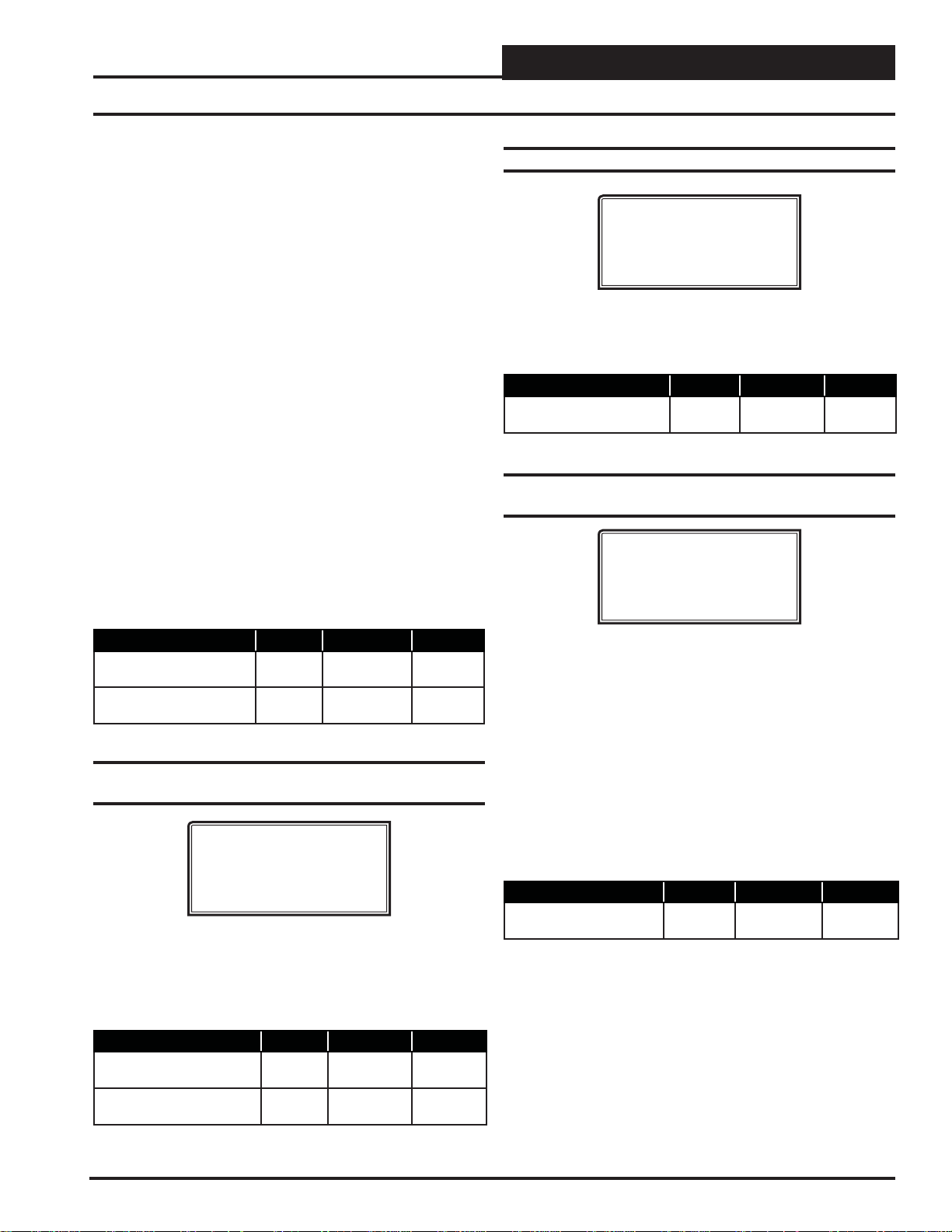
VCC-X SETPOINTS
VCC-X Setpoint Screens
When the exhaust hoods are turned off and the Hood On contact
opens, the unit reverts back to Space or Return Air Temperature
Control and uses the Occupied HVAC Setpoints from the previous
screen.
Space Temperature Control of High Percentage Outside Air
Units—This option allows for Space T emperature control of 100%
Outside Air MUA Units or units with a high percentage of Outdoor
Air (normally 50% or greater). For this application you would confi gure “Space T emperature w/High OA %” for the Controlling Sensor
option. The intent of this sequence is to allow Space Temperature
control of the unit while preventing the dumping of hot or cold
outside air into the space during the Space Vent Mode of operation.
Once the Space Temperature is satisfi ed, before switching to Vent
Mode, the controller compares the Outside Air Temperature to
these Hood On HV AC setpoints to determine if a continued demand
for heating or cooling is required to prevent dumping. If there is
no demand, the VCC-X Controller switches to Vent Mode. If the
Outside Air Temperature is greater than the Hood On HV AC Cooling Setpoint or less than the Hood On HVAC Heating Setpoint,
plus the Occupied Deadband, the VCC-X Controller will continue
mechanical cooling or heating operation and stage it as necessary
to maintain the Vent Mode Supply Air Setpoint (Calculated to be
halfway between the Mode Enable Setpoints).
A call for Heating or Cooling from the Space Sensor will cancel
this tempering operation.
Description Minimum Default Maximum
Hood On OAT Cool 1ºF
(-17.2ºC)
Hood On OAT Heat 1ºF
(-17.2ºC)
75ºF
(24ºC)
70ºF
(21ºC)
110ºF
(43.3ºC)
110ºF
(43.3ºC)
Setpoint Screen #3 - Unoccupied Offsets Cooling & Heating
Setpoint Screen #4 - Mode Deadband
VCC-X Spts ID:#
Mode Deadband
Setpoint: 1.0ºF
This Setpoint is added to and subtracted from the HVAC Mode
Setpoints to determine when the unit enters and leaves a mode of
operation.
Description Minimum Default Maximum
HVAC Mode Select
Deadband
1ºF
(.6ºC)
1ºF
(.6ºC)
10ºF
(5.5ºC)
Setpoint Screen #5 - Space Sensor Slide
Adjust
VCC-X Spts ID:#
Space Sensor
Slide Adj: 0
If the VCC-X has a Space Temperature Sensor with the Slide Adjust option installed, the HVAC Mode Enable Heating and Cooling
Setpoints can be offset by the HVAC Mode Sensor Slide Offset
Setpoint value. When the Slide Adjust bar is in the middle, no offset
will occur. If the Slide Adjust bar is moved all the way to the top of
the Sensor, the Heating and Cooling Setpoints will be raised by the
Setpoint value you have entered. If the Slide Adjust bar is moved all
the way down to the bottom of the Sensor, the Heating and Cooling
Setpoints will be lowered by the Setpoint value you have entered.
VCC-X Spts ID:#
Unoccupied Offsets
Cooling: 30.0ºF
Heating: 30.0ºF
During the Unoccupied Mode of Operation, these Setpoints spread
the HVAC Mode Setpoints out by this user-adjustable amount. Use
only positive numbers for these Setpoints. If you do not want Cooling
or Heating to operate during the Unoccupied Mode, use the default
setting of 30°F for these setpoints.
Description Minimum Default Maximum
Unoccupied Offsets
Cooling
Unoccupied Offsets
Heating
0ºF
(0ºC)
0ºF
(0ºC)
30ºF
(16.6ºC)
30ºF
(16.6ºC)
30ºF
(16.6ºC)
30ºF
(16.6ºC)
VCC-X Operator Interface SD
If the Space Temperature is the SAT Reset Source, then the Slide
Adjust will adjust the HVAC Mode Enable Setpoints and the SAT
Reset Source Setpoints simultaneously.
Description Minimum Default Maximum
Space Sensor
Slide Adjust
0ºF
(0ºC)
0ºF
(0ºC)
10ºF
(5.5ºC)
41
Page 42

VCC-X SETPOINTS
VCC-X Setpoint Screens
Setpoint Screen #6 - Space Sensor
Push-Button Override Duration
VCC-X Spts ID:#
Space Sensor Push
Button Override
Duration: 2.0Hr
If the VCC-X has a Space Temperature Sensor installed and it has
the Override Button option, the HVAC unit will initiate Override
Mode any time the Override Button is pressed and held for less than
3 seconds. This puts the unit into Occupied operation. The PushButton Override Duration Setpoint allows you to adjust the amount
of time the Override will remain in effect when the Override Button
is pressed. To cancel the Override before the Override Duration
time period expires, press the Override Button for 5 to 10 seconds.
If using a Digital Space Sensor, pushing the Override Button momentarily will initiate the Override Mode.
Description Minimum Default Maximum
Space Sensor
Push-Button
Override Duration
0.0 Hr 2.0 Hr 8.0 Hr
Setpoint Screen #8 - Controlling Sensor Low
Alarm Offset
VCC-X Spts ID:#
Controlling Sensor
Low Alarm Offset
Setpoint: 30.0
If the T emperature of the controlling sensor falls below the Occupied
Heating Setpoint by this amount during the Heating Mode, the controller will generate a Low Control Temp Alarm. The unit must be
confi gured for Space T emperature Control, Return Air T emperature
Control, or as a Single Zone VA V unit for this alarm to be generated.
Description Minimum Default Maximum
Controlling Sensor
Low Alarm Offset
0ºF
(0ºC)
30ºF
(16.6ºC)
50º F
(27.7ºC)
Setpoint Screen #9 - Outdoor Dewpoint
Setpoint
VCC-X Spts ID:#
Outdoor Dewpoint
Setpoint: 55.0ºF
Setpoint Screen #7 - Controlling Sensor High
Alarm Offset
VCC-X Spts ID:#
Controlling Sensor
High Alarm Offset
Setpoint: 30.0ºF
If the T emperature of the controlling sensor rises above the Occupied
Cooling Setpoint by this amount during the Cooling Mode, the controller will generate a High Control Temp Alarm. The unit must be
confi gured for Space T emperature Control, Return Air T emperature
Control, or as a Single Zone VA V unit for this alarm to be generated.
Description Minimum Default Maximum
Controlling Sensor
High Alarm Offset
0ºF
(0ºC)
30ºF
(16.6ºC)
50ºF
(27.7ºC)
On MUA confi gured units (100% or high percentage Outdoor Air
units), or if this is a unit in Hood On MUA operation, Dehumidifi ca-
tion will be initiated if the Outdoor Air Dewpoint rises above this
setpoint. If the humidity falls 1% below this setpoint, the unit will
leave the Dehumidifi cation Mode.
Description Minimum Default Maximum
Outdoor Dewpoint
Setpoint
35ºF
(1.7ºC)
55ºF
(12.8ºC)
80ºF
(26.6ºC)
42
VCC-X Operator Interface SD
Page 43

VCC-X SETPOINTS
VCC-X Setpoint Screens
Setpoint Screen #10 - Indoor RH Setpoint Low
and High Reset Source
VCC-X Spts ID:#
Indoor RH Setpoint
Lo Rst Src: 50%
Hi Rst Src: 60%
This screen can be used to set the Space Humidity Setpoint and to
set the Space Humidity Reset range used to reset the Suction Coil
Temperature Setpoint.
On units where Indoor Humidity is used to initiate Dehumidifi cation
(non MUA units), the Low Reset Source (Lo Rst Src) is the Dehumidifi cation Setpoint, and as the Indoor Humidity rises above this
setpoint, Dehumidifi cation will be initiated. If the humidity falls 1%
below this setpoint, the unit will leave the Dehumidifi cation Mode.
If no reset of the Coil T emperature Setpoint is desired, set the High
Reset Source (Hi Rst Src) at the same value as the Low Reset Source.
If reset of the Coil T emperature Setpoint is desired, when the Indoor
Humidity rises above the Low Reset Source, Dehumidifi cation will
be initiated and the Coil Temperature Setpoint will be set at the
Coil T emperature High Reset Limit (confi gured in the next screen).
The High Reset Source (Hi Rst Src) is the Indoor Humidity level at
which the Coil Temperature will be reset to the Coil Temperature
Low Reset Limit (confi gured in the next screen). As the Indoor
Humidity rises between the Low Reset Source and the High Reset
Source, the Coil Temperature Setpoint will be proportionally reset
between the Coil Temperature High Reset Limit down to the Coil
Temperature Low Reset Limit.
Setpoint Screen #11 - Coil (Saturation)
Temperature Low & High Reset Limits
VCC-X Spts ID:#
Coil Temp Setpoint
Hi Rst Lmt: 45ºF
Lo Rst Lmt: 40ºF
Based on the Indoor Humidity Reset Range confi gured on the pre-
vious screen, the Coil Suction (Saturation) Temperature Setpoint
can be reset between the High Reset Limit (Hi Rst Lmt) and Low
Reset Limit (Lo Rst Lmt) confi gured on this screen during the
Dehumidifi cation Mode. See the description of this reset function
on the previous screen. If the High Reset Limit and the Low Reset
Limit are set at the same value, no Coil T emperature Reset will occur .
Description Minimum Default Maximum
Coil Temp Setpoint
High Reset Limit
Coil Temp Setpoint
Lo Reset Limit
35ºF
(1.7ºC)
35ºF
(1.7
ºC)
45ºF
(7.2ºC)
40ºF
(4.5ºC)
70ºF
(21.1ºC)
70ºF
(21.1ºC)
Setpoint Screen #12 - Static Pressure
Setpoint & Deadband
VCC-X Spts ID:#
Static Pressure
Setpoint: 1.50”
Deadband: 0.10”
On MUA units where the Outdoor Dewpoint Setpoint is used to
initiate Dehumidifi cation, this screen is only used to set the Indoor
Humidity values that will reset the Coil T emperature Setpoint. As described above, as the Indoor Humidity rises within the range created
by the Low and High Reset Source Setpoints, the Coil T emperature
Setpoint will be proportionally reset between the High and Low Coil
Temperature Reset Limits.
Description Minimum Default Maximum
Indoor RH Setpoint
Low Reset Source
Indoor RH Setpoint
High Reset Source
0% 50% 100%
0% 60% 100%
For VAV units, a Supply Fan VFD or Bypass Damper Actuator is
used to maintain the Duct Static Pressure Setpoint. The Static Pressure Output Signal varies to control to the Static Pressure Setpoint.
The Duct Static Pressure is maintained at this setpoint anytime the
Main Fan is running.
The Duct Static Setpoint accuracy is controlled by this value. No
Main Fan VFD changes are made if the static is within this range
of this setpoint.
Description Minimum Default Maximum
Static Pressure Spt 0.10″ WG 1.50″ WG 3.0″ WG
Deadband 0.01″ WG 0.10″ WG 0.50″ WG
VCC-X Operator Interface SD
43
Page 44

VCC-X SETPOINTS
VCC-X Setpoint Screens
Setpoint Screen #13 - VFD Speed Minimums
Cool/Vent Modes
VCC-X Spts ID:#
VFD Speed Limits
Min Cool: 30%
Min Vent: 20%
If this unit is confi gured for Single Zone VAV operation, the Min
Cool Percentage will be the fan speed at which the VFD will start
operating at when cooling is initiated. It can then modulate up to
100% as the space temperature rises within the range created by the
Cool Low Reset Source and the Cool High Reset Source Setpoints
entered in Setpoint Screen #16. If this is a CAV or MUA unit, this
should be set to 100%.
The Min Vent Percentage is the speed at which the fan will operate
at during the Vent Mode.
Description Minimum Default Maximum
Minimum Cool 0% 30% 100%
Minimum Vent 0% 20% 100%
Setpoint Screen #14 - VFD Speed Limits Min/
Max Heat
VCC-X Spts ID:#
VFD Speed Limits
Min Heat: 50%
Max Heat: 100%
If this unit is confi gured for Single Zone VAV operation, and you
have a modulating heat source that will allow VA V heating, then the
Min Heat Percentage will be the fan speed at which the VFD will
start operating at when heating is initiated. It can then modulate up
to the Max Heat Percentage as the Space Temperature falls within
the range created by the Heat High Reset Source and the Heat Low
Reset Source created in Setpoint Screen #18. On a standard VAV
unit, if the VFD Signal falls below the Minimum VFD Heat Setpoint
during the Heating Mode, Heating will be disabled. If this is a CAV ,
MUA, or Single Zone VA V with CAV Heating, these setpoints should
both be set at the same value which represents the constant speed
you want the fan to operate at during the Heating Mode.
Description Minimum Default Maximum
Minimum Heat 0% 50% 100%
Maximum Heat
0% 100% 100%
Setpoint Screen #15 - Supply Air Cooling
Setpoint and High Reset Limit
VCC-X Spts ID:#
Supply Air Cooling
Setpoint....: 55.0ºF
Hi Rst Limit: 55.0ºF
If no Reset Source has been confi gured in Confi guration Screen
#10, then this setpoint will be the Supply Air Temperature Cooling
Setpoint. Line 4 will be not be used. If a Reset Source has been
confi gured in Confi guration Screen #10, then Line 4 will be used.
Reset is always upward from the SAT setpoint to the Reset Limit
setpoint. So, the SAT will be the lowest temperature the Supply
Air Setpoint can be reset to and Hi Reset Limit will be the highest
temperature the Supply Air Setpoint can be reset to. The Cooling
Supply Air T emperature Setpoint will automatically be reset warmer
or colder within this range as the Reset Source moves within its
range (created in the next two screens).
Description Minimum Default Maximum
SAT Cooling Setpoint 30ºF
(-1.1
Cool High Reset Limit 0ºF
(-17.7ºC)
ºC)
55ºF
(12.8ºC)
55ºF
(12.8ºC)
80ºF
(26.6ºC)
100ºF
(37.7ºC)
Setpoint Screen #16 - Cool Reset Source
Setpoints - High Reset/Low Reset
VCC-X Spts ID:#
Cool Rst Source Spts
High Reset: 75.0ºF
Low Reset: 70.0ºF
If no SA T Reset Source has been confi gured in Confi guration Screen
#10, you can disregard this screen.
If a temperature Reset Source (Space, Return Air, or Outdoor Air)
has been confi gured in Confi guration Screen #10, then this screen
will allow you to set the range of Reset Source temperatures that
will reset the Supply Air Temperature Setpoint between the limits
that were confi gured in Setpoint Screen #15. At the Cool High Reset
Source T emperature or above, the Supply Air Setpoint will be set to
the Supply Air Cooling Setpoint confi gured in Setpoint Screen #15.
At the Cool Low Reset Source T emperature, the Supply Air Setpoint
will be reset to the Cool Supply Air High Reset Limit confi gured
in Setpoint Screen #15. As the Reset Source temperature moves
between the Low and High Reset Source values (set in this screen),
the Supply Air Temperature Setpoint will be proportionally reset
between the Supply Air Cooling Setpoint and the Cooling High
Reset Limit values set in Setpoint Screen #15.
44
If this unit is confi gured for SZ VA V operation in the Cooling Mode,
the setpoints (Space T emperature only) on this screen will reset the
VCC-X Operator Interface SD
Page 45

VCC-X SETPOINTS
VCC-X Setpoint Screens
VFD fan speed in order to maintain the Space T emperature Cooling
Setpoint. So, if the Space T emperature is at or below the Low Reset
Source value on this screen, the VFD Fan Speed will set at the Min
Cool VFD Speed set in Setpoint Screen #13. If the Space T empera-
ture is at or above the High Reset Source value on this screen, the
VFD Fan Speed will be at 100%. As the Space T emperature moves
between the values set on this screen, the VFD Fan speed will be
proportionally reset between the Min Cool VFD Speed (Setpoint
Screen #13) and 100%. The max fan speed in Cooling is fi xed at
100% and cannot be changed.
If the Reset Source is the Fan VFD Signal or a Remote Voltage
Reset Signal, then the Cool High Reset value will be the VFD
Signal Percentage or the Voltage Signal that will reset the Supply
Air Setpoint to the Supply Air Cooling Setpoint in Setpoint Screen
#15. The Cool Low Reset value will be the VFD Signal Percentage
or the Voltage Signal that will reset the Supply Air Setpoint to the
Supply Air Cool High Reset Limit Setpoint in Setpoint Scr een #15.
Note that for a Voltage Reset, for example, either 0 or 10 volts can
be used for the Cooling Low Reset value based on which voltage
you want to correspond to the Supply Air Cooling High Reset Limit
Setpoint. The opposite voltage would then be used for the Cooling
High Reset value corresponding to the Supply Air Cooling Setpoint.
Description Minimum Default Maximum
High Reset Limit 1ºF
(-17.2ºC)
Low Reset Limit -10ºF
(-23.3
ºC)
75ºF
(24ºC)
70ºF
(21ºC)
150ºF
(65.5ºC)
150ºF
(65.5ºC)
Setpoint Screen #17 - Supply Air Heating
Setpoint and High Reset Limit
VCC-X Spts ID:#
Supply Air Heating
Setpoint: 120.0ºF
Hi Rst Lmt: 120.0ºF
If no Reset Source has been confi gured in Confi guration Screen
#10, then this setpoint will be the Supply Air Temperature Heating Setpoint. Line 4 will not be used. If a Reset Source has
been confi gured in Confi guration Screen #10, then Line 4 will
be used. Reset is always upward from the SAT setpoint to the
Hi Reset Limit setpoint. So, the SAT will be the lowest temperature the Supply Air Setpoint can be reset to and Reset Limit
will be the highest temperature the Supply Air Setpoint can be
reset to. The Heating Supply Air Temperature Setpoint will automatically be reset warmer or colder within this range as the Reset
Source moves within its range (created in the next two screens).
Description Minimum Default Maximum
SAT Heating Spt 40ºF
(4.5
Reset High Limit 0ºF
(-17.7
ºC)
ºC)
120ºF
(48ºC)
120ºF
(48ºC)
240ºF
(115.5ºC)
250ºF
(121.1ºC)
Setpoint Screen #18 - Heat Reset Source
Setpoints - High Reset/Low Reset
VCC-X Spts ID:#
Heat Rst Source Spts
High Reset: 75.0ºF
Low Reset: 70.0ºF
If no SA T Reset Source has been confi gured in Confi guration Screen
#10, you can disregard this screen.
If a temperature Reset Source (Space, Return Air, Outdoor Air)
has been confi gured in Confi guration Screen #10, then this screen
will allow you to set the range of Reset Source temperatures that
will reset the Supply Air Temperature between the limits that were
confi gured in Setpoint Screen #17. At the High Reset Source Tem-
perature, the Supply Air Setpoint will be reset to the Supply Air
Heating Setpoint confi gured in Setpoint Screen #17. At the Low
Reset Source T emperature and below , the Supply Air Setpoint will be
reset to the Heating Supply Air Hi Reset Limit confi gured in Setpoint
Screen #17. As the Reset Source temperature moves between the
Low and High Reset Source values (set in this screen), the Supply
Air Temperature Setpoint will be proportionally reset between the
Supply Air Cooling Setpoint and the High Reset Limit values set
in Setpoint Screen #17.
If this unit is confi gured for SZ VA V operation in the Heating Mode,
the setpoints (Space T emperature only) on this screen will reset the
VFD fan speed in order to maintain the Space Temperature Heating Setpoint. So, if the Space Temperature is at or below the Low
Reset Source value on this screen, the VFD Fan Speed will set at
the Max Heat VFD Speed set in Setpoint Screen #14. If the Space
Temperature is at or above the High Reset Source value on this
screen, the VFD Fan Speed will be at the Min Heat VFD Speed from
Setpoint Screen #14. As the Space Temperature moves between the
High and Low values set on this screen, the VFD Fan speed will be
proportionally reset between the Min and Max Heat VFD Speeds
on Setpoint Screen #14.
If the Reset Source is the Fan VFD Signal or a Remote Voltage
Reset Signal, then the Heat High Reset value will be the VFD
Signal Percentage or the Voltage Signal that will reset the Supply
Air Setpoint to the Supply Air Heating Setpoint in Setpoint Screen
#17. The Heat Low Reset value will be the VFD Signal Percentage
or the Voltage Signal that will reset the Supply Air Setpoint to the
Supply Air Heating High Reset Limit Setpoint in Setpoint Screen
#17. Note that for a Voltage Reset, for example, either 0 or 10 volts
can be used for the Heating Low Reset value based on which voltage you want to correspond to the Supply Air Heating High Reset
Limit Setpoint. The opposite voltage would then be used for the
Supply Air Heating High Reset value corresponding to the Supply
Air Heating Setpoint.
Description Minimum Default Maximum
High Reset Limit 1ºF
(-17.7ºC)
Low Reset Limit -30ºF
(-34.4ºC)
75ºF
(24ºC)
70ºF
(21ºC)
150ºF
(65.5ºC)
150ºF
(65.5ºC)
VCC-X Operator Interface SD
45
Page 46

VCC-X SETPOINTS
VCC-X Setpoint Screens
Setpoint Screen #19 - Stage Off Window Cooling/Heating
VCC-X Spts ID:#
Stage Off Window
Cooling: 5.0ºF
Heating: 5.0ºF
When the VCC-X Controller is in Cooling Mode, if the Supply Air
Temperature drops below the Active Supply Air Cooling Setpoint
minus the Cooling Stage Off W indow value, a Cooling Stage will be
deactivated after its Minimum Run Time. In the Heating Mode, if the
Supply Air Temperature rises above the Active Supply Air Heating
Setpoint plus the Heating Stage Off W indow value, a Heating stage
will be deactivated after its Minimum Run Time.
Description Minimum Default Maximum
Stage Off Window Cooling 1ºF
(.6
Stage Off Window Heating 1ºF
(.6ºC)
ºC)
5ºF
(2.8ºC)
5ºF
(2.8ºC)
30ºF
(16.6ºC)
50ºF
(27.7ºC)
Setpoint Screen #20 - Mod Heat Proportional
Window and Time Period
VCC-X Spts ID:#
Mod Heat
Prop Window: 10.0ºF
Time Period: 30s
The Modulating Heating Proportional Window is the control range
of the Modulating Signal above and below the Active Supply Air
Temperature Setpoint. The size of the Proportional Window will
determine how much of a signal change the controller will make
per Time Period for every 1˚F the Supply Air Temperature is from
setpoint. The maximum signal change per time period is 10% which
occurs when the Supply Air Temperature is the full Proportional
Window amount from setpoint. So, with a 5˚ Proportional W indow ,
if the Supply Air T emperature is 5˚ or more from setpoint, the signal
change will be 10% per time period. At 4˚ difference, the signal
change will be 8% per time period. By the time the difference is 1˚,
the signal change will be 2% per time period. With a Proportional
Window of 2˚, if you are 2˚ or more from setpoint, the amount of
signal change will be 10% per time period, and at 1˚ from setpoint
the change would be 5% per time period. So, a larger proportional
window allows for fi ner tuning of the control signal to prevent
overshooting.
Description Minimum Default Maximum
Mod Heat Proportional
Window
Mod Heat Time Period 5 sec 30 sec 240 sec
.1ºF
(.1ºC)
10ºF
(5.5ºC)
30ºF
(16.6ºC)
Setpoint Screen #21 - Mod Cool Proportional
Window and Time Period
VCC-X Spts ID:#
Mod Cool
Prop Window: 10.0ºF
Time Period: 30s
The Modulating Cooling Proportional Window is the control range
of the Modulating Signal above and below the Active Supply Air
Temperature Setpoint. The size of the Proportional Window will
determine how much of a signal change the controller will make
per Time Period for every ˚F the Supply Air Temperature is from
setpoint. The maximum signal change per time period is 10% when
the Supply Air T emperature is the full Proportional W indow amount
from setpoint. So, with a 5˚ Proportional Window, if the Supply Air
Temperature is 5˚ or more from setpoint, the signal change will be
10% per time period. At 4˚ dif ference, the signal change will be 8%
per time period. By the time the difference is 1˚, the signal change
will be 2% per time period. With a Proportional Window of 2˚, if
you are 2˚ or more from setpoint, the amount of signal change will
be 10% per time period, and at 1˚ from setpoint the change would
be 5% per time period. So, a larger proportional window allows for
fi ner tuning of the control signal to prevent overshooting.
The Time Period is the length of time between Modulating Signal
adjustments. Short Time Periods may cause hunting of the Modulating Signal.
Description Minimum Default Maximum
Mod Cool Proportional
Window
Mod Cool Time Period 5 sec 30 sec 240 sec
.1ºF
(.1ºC)
10ºF
(5.5ºC)
30ºF
(16.6ºC)
The Time Period is the length of time between Modulating Signal
adjustments. Short Time Periods may cause hunting of the Modulating Signal.
46
VCC-X Operator Interface SD
Page 47

VCC-X SETPOINTS
VCC-X Setpoint Screens
Setpoint Screen #22 - Head Pressure
Setpoints - Cooling and Reheat
VCC-X Spts ID:#
Head Pressure Spts
Cooling: 340psi
Reheat: 390psi
If a Head Pressure Transducer is connected to the RSMV Module
you can control a Condenser Fan or a Condenser Water Valve to
maintain these Head Pressure Setpoints in the Cooling and Dehumidifi cation Reheat Modes.
Description Minimum Default Maximum
Cooling Head Pressure
Setpoint
Reheat Head Pressure
Setpoint
240 PSI 340 PSI 420 PSI
240 PSI 390 PSI 420 PSI
Setpoint Screen #23 - Economizer Enable
Setpoint
VCC-X Spts ID:#
Economizer Enable
Setpoint: 72.0ºF
If this unit has been confi gured for Economizer control and an Out-
door Humidity Sensor is not connected to the VCC-X Controller, if
the Outdoor Temperature falls below this setpoint, the Economizer
can be used for free cooling. If a combination Outdoor Air Temperature/Humidity Sensor is connected to the VCC-X Controller and
the W etbulb or Dewpoint Temperature falls below this setpoint, the
Economizer can be used for free cooling.
Description Minimum Default Maximum
Economizer Enable -30ºF
(-34.4
ºC)
55ºF
(12.8ºC)
80ºF
(26.6ºC)
Description Minimum Default Maximum
Economizer Min Position 0% 10% 100%
Setpoint Screen #25 - Maximum Economizer
Position in Heat Mode
VCC-X Spts ID:#
Max Econo Pos In
Heat Mode: 50%
This Setpoint allows you to set the Maximum Position the Outdoor
Air Damper will open to while Heating is operating. This takes priority over the Economizer Maximum Position in High CO
Description Minimum Default Maximum
Maximum Economizer
Position in Heat Mode
0% 50% 100%
Setpoint.
2
Setpoint Screen #26 - Minimum Outdoor
Airfl ow Setpoint & Deadband
VCC-X Spts ID:#
Min. Outdoor Airflow
Setpoint.: 2.00kCFM
Deadband.: 200CFM
If controlling the Outdoor Air Damper to an airfl ow setpoint, this
screen allows you to set the design Minimum Outdoor Air CFM
Setpoint. The Deadband controls the rate of change for the damper
signal. As OA CFM moves further from setpoint within this window ,
the damper makes a larger change.
Description Minimum Default Maximum
Minimum Outdoor
Airfl ow Setpoint
Deadband 10 CFM 200 CFM 9999 CFM
0.10 kCFM 2.00 kCFM 200 kCFM
Setpoint Screen #24 - Economizer Minimum
Damper Position
VCC-X Spts ID:#
Economizer Min
Damper Pos: 10%
The Economizer (OA Damper) Minimum Position Setpoint is
maintained during the Occupied Mode even if the Economizer is
disabled due to the OA Temperature being above the Economizer
Enable Setpoint.
VCC-X Operator Interface SD
47
Page 48

VCC-X SETPOINTS
VCC-X Setpoint Screens
Setpoint Screen #27 - Economizer Maximum
Position in High CO2 Level
VCC-X Spts ID:#
Econo Max Pos In
High CO2.: 50%
This Setpoint allows you to set the Maximum Position the Economizer will open if high CO2 conditions occur in the space. The
Maximum Economizer Position Setpoint is used to limit the amount
of Outdoor Air that will be introduced to the HVAC unit in order to
ensure the unit is operating within its Heating and Cooling design
limitations. As shown in the table that follows, the Minimum setting
for this Setpoint is the value previously set for the Economizer Min
Position Setpoint.
CO
override cannot be used in conjunction with airfl ow control of
2
the Outdoor Air damper (previous screen) in this version.
Description Minimum Default Maximum
Maximum Economizer
Position In High CO
2
Economizer
Min Position
50% 100%
Setpoint Screen #28 - CO2 Setpoints Min/Max
Setpoint Screen #29 - CO2 Altitude Setpoint
VCC-X Spts ID:#
Altitude
Setpoint: 1000ft
Enter the distance above sea level for the installed CO2 Sensor. Altitude
correction is required for valid readings if you are above 500 feet. High
limit = 15,000 feet; Low limit = 0 feet.
Description Minimum Default Maximum
Altitude Setpoint 0 Feet 1000 Ft. 15,000 Ft.
Setpoint Screen #30 - Building Pressure
Setpoint & Deadband
VCC-X Spts ID:#
Building Pressure
Setpoint: 0.02”
Deadband: 0.01”
The VCC-X can maintain Building Static Pressure anytime the
Supply Fan is operating. A Building Pressure Transducer must be
connected to the VCC-X. The following are the available control
options.
VCC-X Spts ID:#
CO2 Setpoints
Min CO2: 900ppm
Max CO2: 1000ppm
The Min CO2 Setpoint is the threshold CO2 level at which the Economizer Min Damper Position (Setpoint Screen #24) will begin to be
reset higher. The Max CO
Setpoint is the CO2 level at which the
2
Economizer Min Damper Position will be reset to the Econo Max
Pos In High CO
(Setpoint Screen #27). In between those CO2 lev-
2
els, the Economizer Minimum Position will be proportionally reset
between the values set in Setpoint Screens #24 and #27.
Description Minimum Default Maximum
Minimum CO2 Level 0 PPM 900 PPM 2000 PPM
Maximum CO
Level 0 PPM 1000 PPM 2000 PPM
2
Direct Acting Building Pressure Control
• On/Off Exhaust Fan—If an On/Off Exhaust Fan is
being used, a relay output must be confi gured for
“Exhaust Fan”. This relay will energize whenever the
Building Pressure rises above the Building Pressure
Setpoint by the Deadband amount. The relay will de energize when the Building Pressure falls below the
Building Pressure Setpoint by the Deadband amount.
• Exhaust Fan VFD or Modulating Exhaust
Damper—If confi gured for Modulating Exhaust, a user-
adjustable voltage output (AOUT4 – Building Pressure
Output on the VCC-X) will be used to control this fan or
damper. An Exhaust Relay can be confi gured if
necessary to enable the fan or damper. Whenever the
Building Pressure rises above the Building Pressure
Setpoint by the Deadband amount, the Exhaust Fan
Relay will energize and the Modulating Signal will
activate to control to the Building Pressure Setpoint. If
the Building Pressure falls below the Building Pressure
Setpoint by the Deadband amount, the Modulating
Signal will modulate towards 0% as it attempts to
maintain the Building Pressure Setpoint. The Exhaust
Fan Relay remains energized as long as the Modulating
Signal is above 0%.
48
VCC-X Operator Interface SD
Page 49

VCC-X SETPOINTS
VCC-X Setpoint Screens
Reverse Acting Building Pressure Control
• Outdoor Air Damper—If this option is confi gured,
the VCC-X will use the user-adjustable Economizer/
Outdoor Air Damper output signal (AOUT2 –
Economizer Control Signal) to maintain the Building
Pressure Setpoint. Whenever the Building Pressure
falls below the Building Pressure Setpoint by the
Deadband amount, the modulating Economizer Output
Signal will modulate the damper open to control to
the Building Pressure Setpoint. If the Building Pressure
rises above the Building Pressure Setpoint by the
Deadband amount, the damper will modulate towards
closed as it attempts to maintain the Building Pressure
Setpoint. When this option is selected, no Economizer
free cooling or CO
IAQ operation will be available.
2
• Supply Fan VFD – Contact WattMaster regarding this
Reverse Acting Building Pressure Control option. It
should not be used in most applications. If this option
is selected, the user-adjustable Supply Fan VFD Output
(AOUT1 on the VCC-X) will be used to control the
Supply Fan VFD to maintain the Building Pressure
Setpoint in similar fashion to the Outdoor Air Damper
control described above.
Setpoint Screen #32 - OAT Lockouts - Heat
VCC-X Spts ID:#
OAT Lockouts
Heat: 90.0ºF
The VCC-X will Lockout Mechanical Heating when the Outdoor
Air Temperature is above this Setpoint.
Description Minimum Default Maximum
OAT Lockouts Heating -30ºF
(34.4
ºC)
90ºF
(32.2ºC)
150ºF
(65.5ºC)
Setpoint Screen #33 - Supply Air Cutoffs Cooling/Heating
VCC-X Spts ID:#
Supply Air Cutoffs
Cooling: 40.0ºF
Heating: 150.0ºF
Description Min. Default Max.
Building Pressure Spt -0.20″ WG 0.02″ WG 0.20″ WG
Building Pressure
Deadband
0.01″ WG 0.01″ WG 0.10″ WG
Setpoint Screen #31 - OAT Lockouts Comp Cool/Comp Heat
VCC-X Spts ID:#
OAT Lockouts
Comp Cool: 50.0ºF
Comp Heat: 35.0ºF
The VCC-X will Lockout Compressor (Mechanical) Cooling and
Heat Pump Compressor Heating when the Outdoor Air T emperature
is below these Compressor Cool and Heat Lockout Setpoints.
Description Minimum Default Maximum
OAT Lockout
Compressor Cooling
OAT Lockout
Compressor Heating
-30ºF
ºC)
(-34.4
-30ºF
(-34.4ºC)
50ºF
(10ºC)
35ºF
(1.6ºC)
100ºF
(37.7ºC)
100ºF
(37.7ºC)
The VCC-X controller will temporarily disable Heating or Cooling
if while in Heating or Cooling Mode the Supply Air Temperature
rises above the Hi SAT Cutoff Heating Setpoint or falls below the
Lo SA T Cutof f Cooling Setpoint. See the VCC-X Controller Techni-
cal Guide for detailed information on the Low and High Supply Air
Temperature Cutoff sequence of operation.
Description Minimum Default Maximum
Cooling SAT Cutoff 0ºF
(-17.7ºC)
Heating SAT Cutoff 0ºF
(-17.7
ºC)
40ºF
(4.5ºC)
150ºF
(65.5ºC)
100ºF
(37.7ºC)
250ºF
(121.1ºC)
Setpoint Screen #34 - Mod Heat Output
Position in Off Mode
VCC-X Spts ID:#
Mod Heat Output Pos
In Off Mode: 0%
This screen can be used to ensure that a Modulating Hot Water
Valve will open to a certain position when the fan is not operating
in order to prevent freezing. For other forms of Modulating Heat,
this would normally be set to 0%.
VCC-X Operator Interface SD
Description Minimum Default Maximum
Mod Heat Output
Position in Off Mode
0% 0% 100%
49
Page 50

VCC-X SETPOINTS
VCC-X Setpoint Screens
Setpoint Screen #35 - Preheat Relay Setpoint
VCC-X Spts ID:#
Preheat Relay
Setpoint: 30.0ºF
For cold climates where freezing temperatures may be experienced,
a Pre-Heater relay output can be activated to control a preheat coil
based on the Outdoor Air Temperature to prevent freezing of Water
Coils. One of the VCC-X Relay Outputs must be confi gured for the
Pre-Heater control. When confi gured, any time the Outdoor Air T em-
perature falls below the Preheat Setpoint during Occupied Mode and
the HVAC unit’s fan is running, the Pre-Heater relay will activate.
This setpoint will also be used to enable the PREHEAT-X Controller if it is being used in conjunction with the VCC-X Controller.
Description Minimum Default Maximum
Preheat Setpoint -30ºF
(-34.4ºC)
30ºF
(-1.1ºC)
70ºF
(21.1ºC)
Setpoint Screen #36 - Low Ambient Setpoint
VCC-X Spts ID:#
Low Ambient
Setpoint: 30.0ºF
Similar to the Pre-Heat Relay, a Low Ambient Relay can be confi g-
ured to energize anytime (during Occupied or Unoccupied Mode)
the Outdoor Air Temperature falls below this setpoint. The Low
Ambient Relay, though, can energize whether the fan is running or
not. This could be used to energize a boiler, for instance.
Description Minimum Default Maximum
Low Ambient Setpoint -30ºF
(-34.4ºC)
30ºF
(-1.1ºC)
70ºF
(21.1ºC)
Setpoint Screen #37 - Heat Wheel Defrost
Temperature Setpoint
Setpoint Screen #38 - Morning Warm Up Max
Length & Target Temp
VCC-X Spts ID:#
Morning WarmUp
Max Length: 60 Min
Target Temp: 70.0º F
When the VCC-X is confi gured for Morning Warm-up and the con-
troller enters the Occupied Mode, the VCC-X looks at the Return
Air Temperature to determine if the unit should initiate Morning
W arm-up Mode. If the Return Air T emperature is below the Morning
Warm-up Target Temperature and the Max Length is greater than
“0,” the VCC-X will initiate Heating. This is considered Morning
W arm-up and will run until the Return Air Temperature rises above
the Morning W arm-up Target Temperature or until the Max Length
Setpoint time expires.
Description Minimum Default Maximum
Morning Warm Up
Max Length
Morning Warm Up
Target Temp
0 Min 60 Min 240 Min
50ºF
(10ºC)
70ºF
(21ºC)
90ºF
(32.2ºC)
Setpoint Screen #39 - SZ VAV Integral
Constant
VCC-X Spts ID:#
SZ VAV Integral
Constant: 0
If the SZ VAV Fan Speed Control requires Integral control, enter
the Integral constant here.
Description Minimum Default Maximum
SZ VAV Integral Constant 0 0 10
VCC-X Spts ID:#
Heat Wheel Defrost
Temp Setpoint: 30.0ºF
The unit will go into Heat Wheel Defrost Mode when the Outdoor
Air is below this setpoint.
Description Minimum Default Maximum
Heat Wheel Defrost 0ºF
(0ºC)
30ºF
(-1.1ºC)
50ºF
(10ºC)
50
VCC-X Operator Interface SD
Page 51

VCC-X SETPOINTS
VCC-X Setpoint Screens
Setpoint Screen #40 - Return Air Bypass
Damper Factor Setpoint
VCC-X Spts ID:#
Return Air Bypass
Damper Factor
Setpoint: 40%
This setpoint is used when you have an EM1 Expansion Module
installed and confi gured for Return Air Bypass Damper control. The
Return Air Bypass Damper Factor Setpoint is a percentage value
that is used to calculate the Return Air Damper position in relation
to the Return Air Bypass Damper position. This provides a method
for adjusting the airfl ow through the Return Air Bypass Damper.
Increasing this percentage increases the airfl ow through the Return
Air Bypass Damper by causing the Return Air Damper to move fur ther towards its closed position in relation to the Return Air Bypass
Damper moving towards its open position.
Description Minimum Default Maximum
Damper Factor 0% 40% 100%
Setpoint Screen #41 - Warm-Up Supply Air
Temperature Setpoint
Setpoint Screen #43 - PREHEAT-X Cool Mode
and Heat Mode Setpoints
VCC-X Spts ID:#
Preheat-X Spts
Cool Mode: 40.0ºF
Heat Mode: 60.0ºF
If using the Preheat-X Controller with the VCC-X, this screen allows you to set the Preheat setpoint you want to control to during
the Cooling and the Heating Modes.
Description Minimum Default Maximum
Preheat-X Cool Mode
Setpoint
Preheat-X Heat Mode
Setpoint
35.0ºF
(1.66ºC)
35.0ºF
(1.66
ºC)
40.0ºF
(4.5ºC)
60.0ºF
(15.5ºC)
90.0ºF
(32.2ºC)
90.0ºF
(32.2ºC)
Setpoint Screen #44 - PREHEAT-X Vent Mode
Setpoint
VCC-X Spts ID:#
Preheat-X Spts
Vent Mode: 50.0ºF
VCC-X Spts ID:#
Warmup Supply Air
Setpoint: 100.0ºF
Heating will be controlled to this Supply Air Setpoint during Morning W arm-Up.
Description Minimum Default Maximum
Warm-Up SAT Setpoint 40ºF
(4.44
ºC)
100ºF
(37.78ºC)
240ºF
(115.56ºC)
Setpoint Screen #42 - Cool-Down Supply Air
Temperature Setpoint
VCC-X Spts ID:#
Cooldown Supply Air
Setpoint: 55.0ºF
Cooling will be controlled to this Supply Air Setpoint during CoolDown.
Description Minimum Default Maximum
Cool-Down SAT Setpoint 30ºF
(-1.11
ºC)
55ºF
(12.78ºC)
80ºF
(26.67ºC)
If using the Preheat-X Controller with the VCC-X, this screen allows you to set the Preheat setpoint you want to control to during
the Vent Mode.
Description Minimum Default Maximum
Preheat-X Vent Mode
Setpoint
35.0ºF
(1.66
ºC)
50.0ºF
(10.0ºC)
90.0ºF
(32.2ºC)
Setpoint Screen #45 - Superheat Setpoint
VCC-X Spts ID:#
Superheat
Setpoint: 15ºF
The Superheat Setpoint is the target Superheat used by the Refrigerant Module to correctly drive the EXV valves.
Description Minimum Default Maximum
Superheat Setpoint 1ºF
(-17.2ºC)
15ºF
(-16.9ºC)
30ºF
(-1.11ºC)
VCC-X Operator Interface SD
51
Page 52

VCC-X SETPOINTS
VCC-X Setpoint Screens
Setpoint Screen #46 - Space Sensor
Calibration - Current and Offset
VCC-X Spts ID:#
Space Sensor Cal
Current: 0.0ºF
Offset.: 0.0ºF
If the Space Air Temperature Sensor is reading incorrectly, you can
use this option to enter an offset temperature to adjust the Sensor’s
Temperature. Line 3 will display the current Space Air T emperature
reading. Enter a positive Sensor Calibration value in Line 4 to raise
the Space Temperature Sensor reading or a negative value in Line
4 to lower the Sensor reading.
Description Minimum Default Maximum
Space Sensor
Calibration Offset
-100.0ºF
(-55.5ºC)
0.0ºF
(0ºC)
100.0ºF
(55.5ºC)
Setpoint Screen #47 - Return Air Temperature
Sensor Calibration - Current and Offset
VCC-X Spts ID:#
Return Sensor Cal
Current: 0.0ºF
Offset.: 0.0ºF
Setpoint Screen #48 - SAT Sensor Calibration
- Current and Offset
VCC-X Spts ID:#
SAT Sensor Cal
Current: 0.0ºF
Offset.: 0.0ºF
If the Supply Air T emperature Sensor is reading incorrectly , you can
use this option to enter an offset temperature to adjust the Sensor’s
Temperature. Line 3 will display the current Supply Air T emperature
Sensor reading. Enter a positive Sensor Calibration value in Line
4 to raise the Supply Air Temperature Sensor reading or a negative
value in Line 4 to lower the Sensor reading.
Description Minimum Default Maximum
Sensor Calibration SAT -100.0ºF
(-55.5ºC)
0.0ºF
(0ºC)
100.0ºF
(55.5ºC)
If the Return Air T emperature Sensor is reading incorrectly , you can
use this option to enter an offset temperature to adjust the Sensor’s
Temperature. Line 3 will display the current Return Air T emperature
reading. Enter a positive Sensor Calibration value in Line 4 to raise
the Return Temperature Sensor reading or a negative value in Line
4 to lower the Sensor reading.
Description Minimum Default Maximum
Return Air Sensor
Calibration Offset
-100.0ºF
(-55.5ºC)
0.0ºF
(0ºC)
100.0ºF
(55.5ºC)
52
VCC-X Operator Interface SD
Page 53
Setpoint Screen #49 - OAT Sensor Calibration
- Current and Offset
VCC-X Spts ID:#
OAT Sensor Cal
Current: 0.0ºF
Offset.: 0.0ºF
If the Outdoor Air Temperature Sensor is reading incorrectly, you
can use this option to enter an offset temperature to adjust the
Sensor’s Temperature. Line 3 will display the current Outdoor Air
Temperature Sensor Reading. Enter a positive Sensor Calibration
value in Line 4 to raise the Outdoor Air T emperature Sensor reading
or a negative value in Line 4 to lower the Sensor reading.
Description Minimum Default Maximum
OAT Sensor Calibration
Offset
-100.0ºF
(-55.5ºC)
0.0ºF
(0ºC)
100.0ºF
(55.5ºC)
VCC-X SETPOINTS
VCC-X Setpoint Screens
Setpoint Screen #50 - CO2 Sensor Calibration
- Current and Offset
VCC-X Spts ID:#
CO2 Sensor Cal
Current: 0ppm
Offset.: 0ppm
If the CO2 Sensor is reading incorrectly, you can use this option
to enter an offset reading to adjust the Sensor’s Sensitivity. Line 3
will display the current CO2 Sensor reading. Enter a positive Sensor
Calibration value in Line 4 to increase the CO2 Sensor reading or a
negative value in Line 4 to lower the Sensor reading.
Description Minimum Default Maximum
Sensor Calibration CO
-500.0 PPM 0.0 PPM 500.0 PPM
2
VCC-X Operator Interface SD
53
Page 54

VCC-X STATUS
VCC-X Status Screens
Zone
Zone
VCC-X Status Screen Index
The available Status Screens for the VCC-X Controller are listed on
the next few pages by sequential screen number. The following is a
list of all the VCC-X Status Screens in numerical order with a brief
listing of the Status features available on each screen:
Screen #1 Date & Time
Screen #2 Application Type, Schedule Mode &
HVAC Mode
Screen #3 Controlling Temperature, Cooling & Heating
Setpoints
Screen #4 Space & Return Air Temperature &
Slide Adjust
Screen #5 Supply Air Temperature & Active Setpoint
Screen #6 Cooling Enabled: Yes/No
Screen #7 Cooling Outputs - Active Stages &
Mod Cooling Position
Screen #8 Heating Enabled Yes/No
Screen #9 Heating Outputs - Active Stages & Mod Heat
Position
Screen #10 MODGAS-X Enabled or Disabled and /
MODGAS-X Heating Output Signal
Screen #11 Current Space RH & Indoor RH Setpoint &
Return RH
Screen #12 MHGRV-X Enabled or Disabled and
MHGRV-X Reheat Valve Output Signal
Percentage
Screen #13 Preheat-X Enabled and Leaving Air
Temperature Setpoint
Screen #14 Current Preheat-X Leaving Air Temperature
and Entering Air Temperature
Screen #15 Current Preheat-X Modulating Position and
Active Stages
Screen #16 Current Outdoor Air Drybulb and Current
Outdoor Air Relative Humidity
Screen #17 Current Wetbulb Temperature and Current
Calculated Outdoor Air Dewpoint Temperature
Screen #18 Economizer Enabled or Disabled and Current
Economizer Open Percentage
Screen #19 Economizer Feedback Percentage for Title 24
Economizer
Screen #20 Economizer in IAQ Mode Yes/No and
Economizer Minimum Percentage
Screen #21 Current CO
Maximum Setpoint
Screen #22 Outdoor Air CFM and Supply Air CFM
Screen #23 Return Air CFM and Exhaust Air CFM
Screen #24 Current Duct Static Pressure, Current Duct
Static Pressure Setpoint and Output Percentage
Screen #25 Current Building Pressure and Setpoint
Screen #26 Building Pressure Exhaust Fan Status and
Output Signal Percentage
Screen #27 Return Air Damper Signal & Return Air
Bypass Damper Signal
Screen #28 Reset Voltage Signal
Screens
#29-36 VCC-X Relays
Screens
#37-41 VCC-X EM1 Relays
Screens
#42-53 12 Relay Expansion Module Relays
Screens
#54-## Alarm Status Screens
Level, Minimum Setpoint, and
2
54
VCC-X Operator Interface SD
Page 55

VCC-X STATUS
VCC-X Status Screens
Status Screens - General Procedures
From any menu screen, press <STATUS>. The Unit Selection Screen,
shown below,
Enter the correct unit ID number of the Controller you want to view
press <ENTER>. Once communication is established, the *00*
and
message will go away. Then
Selection Screen(s) below:
Select VCC-X Status. Then press <ENTER>.
The fi rst Status Screen will appear. Press <> to scroll through
the screens.
will appear requesting that you enter the unit ID number.
Enter Unit Address
Then Press Enter
Selected Unit #_1
Press Down
press <>. Y ou will then see the Status
VCC-X Status
RSM #1
RSM #2
Select & Press Enter
RSM #3
RSM #4
Select & Press Enter
Status Screen #2 - Application Type, Schedule
Mode & HVAC Mode
VCC-X v1.02 ID #
App Type
Schedule Mode
HVAC Mode
Line 2 App Type:
Constant Volume Single Zone VAV
VAV VAV w/Tempering
Make Up Air Space w/High OA%
Line 3 Schedule Mode:
Unoccupied Holiday Occupied
Occupied Forced Occupied
Override Forced Unoccupied
Holiday Unoccupied Remote Occupied
Line 4 HVAC Mode:
Off Dehum Vent
Vent Mode Dehum Cool
Cool Mode Dehum Heat
Heat Mode Warm Up
Defrost Cool Down
Remote Cool Remote Heat
Remote Vent RH Remote Cool RH
Remote Heat RH
NOTE: If the *00* remains, it indicates a communication
failure to the controller.
Status Screen #1 - Date and Time
VCC-X v1.02 ID #
Controller Date/Time
01/16/2015 05:00 PM
Line 2 Controller Date/Time
Line 3 MM/DD/YYYY HH:MM XX
(Month, Day, Year) (Hour, Minutes, AM or PM)
VCC-X Operator Interface SD
Status Screen #3 - Controlling Temperature,
Cooling & Heating Setpoints
VCC-X v1.02 ID #
Ctrl Temp: 000.0ºF
Cool Spt: 000.0ºF
Heat Spt: 00.0ºF
Line 2 Controlling T emperatur e
This is the temperature of the sensor that is confi gured as
the HVAC Source (Mode Enable) Sensor. This can be
the Supply Air, Return Air, Outdoor Air, or Space
Temperature Sensor.
Line 3 Cooling Setpoint
Based on the current Occupied/Unoccupied Mode
of operation. (Refl ects any active resets.)
Line 4 Heating Setpoint
Based on the current Occupied/Unoccupied Mode
of operation. (Refl ects any active resets.)
55
Page 56

VCC-X STATUS
VCC-X Status Screens
Zone
Zone
Status Screen #4 - Space and Return
Temperature & Slide Adjust
VCC-X v1.02 ID #
Space Temp: 0.0ºF
Return Temp: 0.0ºF
Slide Adj: 0.0ºF
Line 2 Space Temperature
If you are using a Space Temperature Sensor, this line
will display the current Space Temperature during the
Occupied or Unoccupied Mode. If a Space Temperature
Sensor is not used, it will display 0°F.
Line 3 Return Air Temperature
If you are using a Return Air Temperature Sensor, this
` line will display the current Return Air Temperature
during the Occupied or Unoccupied Mode. If a Return
Air Temperature Sensor is not used, it will display 0°F.
Line 4 Slide Adjust
This is the current value of the Space Temperature offset
based on the position of the slide adjust switch on the
Space Sensor.
Status Screen #5 - Supply Air Temperature &
Active Setpoint
VCC-X v1.02 ID #
Supply Temp: 0.0ºF
Active Spt: 0.0ºF
Status Screen #6 - Cooling Enabled
VCC-X v1.02 ID #
Cooling Enabled
YES/NO
Line 3 Cooling Enabled YES/NO
NO if the Cooling is not enabled.
Outdoor Air Temperature is above the Compressor
Cooling Lockout.
This line will display YES if Cooling is enabled and
Cooling is enabled if the
Status Screen #7 - Cooling Outputs - Active
Stages and Mod Cool Position
VCC-X v1.02 ID #
Cooling Outputs
Active Stages: XX
Mod Cool Pos.: XXX%
Line 2 Cooling Active Stages
This line will display the number of stages of Cooling
that are currently active.
Line 3 Current Modulating Cooling Output Signal
Percentage
Indicates the percentage output signal to the Modulating
Compressor or Chilled Water Valve.
Line 2 Current Supply Air Temperature
The Supply Air Temperature is always required. If a
Supply Air Temperature Sensor is not installed, the
VCC-X Controller will not operate correctly and will
display 0°.
Line 3 Current Active Supply Air Setpoint
This is the Supply Air Setpoint for the mode that the
unit is currently operating in. If the Supply Air Reset is
confi gured, this is the calculated setpoint based on the
current Reset Source conditions.
56
Status Screen #8 - Heating Enabled
VCC-X v1.02 ID #
Heating Enabled
YES/NO
Line 3 Heating Enabled YES/NO
if Heating is not enabled. Heating is enabled if the
Outdoor Air Temperature is below the Heating Lockout.
This line will display YES if Heating is enabled and No
VCC-X Operator Interface SD
Page 57

VCC-X STATUS
VCC-X Status Screens
Status Screen #9 - Heating Outputs - Active
Stages and Mod Heat Position
VCC-X v1.02 ID #
Heating Outputs
Active Stages: XX
Mod Heat Pos.: XXX%
Line 3 Heating Active Stages
This line will display the number of stages of Heating
that are currently active.
Line 4 Current Modulating Heating Output Signal
Percentage
Indicates the percentage output signal being supplied
to a Modulating Heating device when you have
confi gured this option for your HVAC unit.
Status Screen #10 - MODGAS-X Enabled and
Output %
VCC-X v1.02 ID #
MODGAS-X
Enabled: YES/NO
Position: XXX%
Line 3 MODGAS-X Enabled or Disabled
This indicates whether the VCC-X Controller has
enabled the MODGAS-X Controller to begin to operate.
If you do not have a MODGAS-X Controller connected
to the VCC-X Controller, this line will indicate “NO”.
Line 4 Current MODGAS-X Heating Output Signal
Indicates the percentage output signal being supplied
by the MODGAS-X controller when you have one
connected to the VCC-X Controller.
Status Screen #11 - Space RH & Indoor RH
Setpoint
VCC-X v1.02 ID #
Space RH: XXX.X%
Return RH: XXX.X%
RH Setpoint: XXX.X%
Line 2 Current Space Relative Humidity Percentage
If an E-BUS Space Temperature/Humidity Sensor has
been installed and confi gured on the unit, the current
Space Air Relative Humidity Percentage will appear on
this line. If this combination Temperature/Humidity
Sensor is not installed, this line will display 0%.
Line 3 Current Return Air Relative Humidity Percentage
If an E-BUS Return Air Temperature/Humidity Sensor
has been installed and confi gured on the unit, the current
Return Air Relative Humidity Percentage will appear on
this line. If this combination Temperature/Humidity
Sensor is not installed, this line will display 0%.
Line 4 Current Indoor Relative Humidity Setpoint
Percentage
This is the adjustable Indoor Air Relative Humidity
Setpoint Percentage that has been set by the user.
Status Screen #12 - MHGRV-X Enabled and
Output %
VCC-X v1.02 ID #
MHGRV-X
Enabled: YES/NO
Position: XXX%
Line 3 MHGRV-X Enabled or Disabled
This indicates whether the VCC-X Controller has
enabled the MHGRV-X Controller to begin to operate.
If you do not have a MHGRV-X Controller connected to
the VCC-X Controller, this line will indicate “NO”.
Line 4 Current MHGRV-X Reheat Valve Output Signal
Percentage
Indicates the percentage output signal being supplied
by the MHGRV-X Controller when you have one
connected to the VCC-X Controller.
Status Screen #13 - PREHEAT-X Controller
Status and Leaving Air Temperature Setpoint
VCC-X v1.02 ID #
Preheat-X
Enabled: YES/NO
Lvg Air Spt: 0.0ºF
Line 3 PREHEAT-X Enabled or Disabled
enabled the PREHEAT-X Controller to begin to operate.
If you do not have a PREHEAT-X Controller connected
to the VCC-X Controller, this line will indicate “NO”.
Line 4 Leaving Air Temperature Setpoint
This indicates whether the VCC-X Controller has
This is the confi gured Leaving Air Temperature Setpoint.
VCC-X Operator Interface SD
57
Page 58
VCC-X STATUS
VCC-X Status Screens
Zone
Zone
Status Screen #14 - PREHEAT-X Controller
Current Leaving Air and Entering Air
Temperature
VCC-X v1.02 ID #
Preheat-X Temps
Leaving Air: 0.0ºF
Entring Air: 0.0ºF
Line 3 Current PREHEAT-X Leaving Air Temperature
If the Preheat-X Controller (and the associated Leaving
Air Temperature Sensors) is installed and confi gured,
this line will display the current Preheat-X Leaving Air
Temperature.
Line 4 Current PREHEAT-X Entering Air Temperature
If the Preheat-X Controller (and the associated Entering
Air Temperature Sensor) is installed and confi gured, this
line will display the current Preheat-X Entering Air
Temperature.
Status Screen #15 - PREHEAT-X Controller
Modulating Position and Active Stages
Status Screen #16 - OA Drybulb and Humidity
VCC-X v1.02 ID #
Outdoor Conditions
Drybulb: 0.0ºF
Humidity: XXX%
Line 3 Current Outdoor Air Drybulb
If an E-BUS Outdoor Air Temperature/Humidity Sensor
has been installed and confi gured on the VCC-X, the
current Outdoor Air Temperature will display on this
line. If the sensor fails, this line will display a
temperature that is half way between the Cooling and
Heating Lockout Setpoints.
Line 4 Current Outdoor Air Relative Humidity
If an E-BUS Outdoor Air Temperature/Humidity Sensor
has been installed and confi gured on the VCC-X, the
Outdoor Air Relative Humidity Percentage will appear
on this line. If not, this line will display 0%.
Status Screen #17 - OA Wetbulb and Dewpoint
VCC-X v1.02 ID #
Preheat-X Status
Mod Pos: XXX%
Active Stages: X
Line 3 Current PREHEAT-X Modulating Position
If you have a PREHEAT-X Controller connected to
the VCC-X Controller and are using Modulating Heat,
this is the current modulating heat signal
Line 4 Current PREHEAT-X Active Stages
VCC-X Controller, and are using staged heat, this is the
number of stages currently active.
If you have a PREHEAT-X Controller connected to the
.
VCC-X v1.02 ID #
Outdoor Conditions
Wetbulb: 0.0ºF
Dewpoint: 0.0ºF
Line 3 Current Wetbulb Temperature
If an E-BUS Outdoor Air Temperature/Humidity Sensor
has been installed and confi gured on the unit, this line
will display the calculated Outdoor Air Wetbulb
Temperature. If not, it will display 0°F.
Line 4 Current Calculated Outdoor Air Dewpoint
Temperature
If an E-BUS Outdoor Air Temperature/Humidity Sensor
has been installed and confi gured on the unit, the
calculated Outdoor Air Dewpoint Temperature will
appear on this line. If not, this screen displays 0°F.
58
VCC-X Operator Interface SD
Page 59
VCC-X STATUS
VCC-X Status Screens
Status Screen #18 - Economizer Enabled and
Economizer Position
VCC-X v1.02 ID #
Economizer
Enabled: YES/NO
Position: XXX%
Line 3 Economizer Enabled
This line will display YES if the Economizer is enabled
and NO if the Economizer is not enabled. The
Economizer is enabled whenever the Economizer Enable
Temperature (options: Drybulb, Wetbulb or Dewpoint)
is below the Economizer Enable Setpoint.
Line 4 Current Economizer Open Percentage
This shows the percentage signal currently being sent to
the Economizer (Outdoor Air Damper), whether the unit
is confi gured for Economizer Control or simply has a
Minimum Outdoor Air Damper position confi gured. If
Economizer Control is not confi gured, it will display
0%.
Status Screen #19 - Title 24 Economizer
Feedback
VCC-X v1.02 ID #
Economizer
Feedback: XXX%
[Only For Title 24]
Line 4 Economizer Minimum Percentage
This shows the current Economizer (OA) Minimum
Damper Position. If the unit is not in IAQ Mode, this
will be the regular confi gured Minimum Damper
Position. If the unit is in IAQ Mode, this will show the
re-calculated Minimum Damper Position.
Status Screen #21 - CO2 Level and Setpoints
VCC-X v1.02 ID #
CO2 Level: XXXXppm
Min Setpt: XXXXppm
Max Setpt: XXXXppm
Line 2 Current CO2 Level
Indicates the CO
Level. You must install and confi gure a
2
CO2 Sensor to display the CO2 Level. If a CO2 Sensor is
not installed and confi gured, this line will display 0
PPM.
Line 3 Minimum CO
This is the Minimum CO
Setpoint
2
Setpoint that was confi gured
2
in Setpoint Screen #28.
Line 4 Maximum CO
This is the Maximum CO
Setpoint
2
Setpoint that was confi gured
2
in Setpoint Screen #28.
Status Screen #22 - Outdoor Air CFM & Supply
Air CFM
Line 3 Title 24 Economizer Open Percentage
If confi gured for Title 24 Economizer operation, this
shows the Outdoor Air Damper Feedback Signal
percentage. If Title 24 Economizer Control is not
confi gured, it will display 0%.
Status Screen #20 - Economizer in IAQ Mode
and Minimum Economizer Position
VCC-X v1.02 ID #
Econo in IAQ Mode
YES/NO
Econo Min Pos: XXX%
Line 3 Economizer in IAQ Mode
This line will display YES if the Economizer (OA)
Minimum Damper Position has been overridden based
on CO
IAQ operation.
2
VCC-X Operator Interface SD
VCC-X v1.02 ID #
Outdoor kCFM: XXX.XX
Supply kCFM: XXX.XX
Line 2 Outdoor Air CFM
If an Outdoor Air airfl ow monitoring station is being
used, this is the current CFM reading of that device.
K = 1000
Line 3 Supply Air CFM
If a Supply Air airfl ow monitoring station is being used,
this is the current CFM reading of that device.
K = 1000
59
Page 60

VCC-X STATUS
VCC-X Status Screens
Zone
Zone
Status Screen #23 - Return Air CFM & Exhaust
Air CFM
VCC-X v1.02 ID #
Return kCFM: XXX.XX
Exhaust kCFM: XXX.XX
Line 2 Return Air CFM
If a Return Air airfl ow monitoring station is being used,
this is the current CFM reading of that device. K = 1000
Line 3 Exhaust Air CFM
If an Exhaust Air airfl ow monitoring station is being
used, this is the current CFM reading of that device.
K = 1000
Status Screen #24 - Duct Static Pressure
Setpoint & Output %
VCC-X v1.02 ID #
Static Pr: X.XX”
Setpoint: X.XX”
Output: XXX%
Status Screen #25 - Building Pressure & Setpoint
VCC-X v1.02 ID #
Building Pressure
Pressure: XXX”
Setpoint: X.XX”
Line 3 Current Building Pressure
Indicates the current Building Pressure. This display
requires the installation of a Building Pressure Sensor.
If you don’t have a Building Pressure Sensor correctly
installed and wired to the controller, this line will
display “0.0”.
Line 4 Building Pressure Setpoint
This is the Building Static Pressure Setpoint confi gured
in Setpoint Screen #30.
If you have not confi gured Building Pressure Control,
this line will display [No Press Out Confg].
Status Screen #26 - Building Pressure Exhaust
Fan and Output %
Line 2 Current Duct Static Pressure
Requires the installation and wiring of a Duct Static
Pressure Sensor. If you do not have a Duct Static
Pressure Sensor correctly installed and wired to the
controller, this line will display “0.0”.
Line 3 Duct Static Pressure Setpoint
This is the Duct Static Pressure Setpoint confi gured in
Setpoint Screen #12.
Line 4 Current Duct Static Pressure Output Signal
Percentage
Indicates the output signal percentage being supplied to
the VFD Supply Fan or Bypass Damper Actuator when
you have confi gured one of these options for your
HVAC unit.
If you have not confi gured Duct Static Pressure Control,
this line will display [No Press Out Confg].
VCC-X v1.02 ID #
Building Pressure
Exhaust Fan: ON/OFF
Output: XXX%
Line 3 Building Pressure Exhaust Fan Status
Indicates whether the Exhaust Fan Relay is On or Off.
Line 4 Current Building Pressure Output Signal Percentage
Indicates the output signal percentage being supplied to
the building pressure control fan or damper. For Direct
Acting control, this would be to an Exhaust Fan VFD or
a Modulating Exhaust Damper. For Reverse Acting
control, this would be to the Outdoor Air Damper or
Supply Fan VFD.
If you have not confi gured Building Pressure Control,
this line will display [No Press Out Confg].
60
VCC-X Operator Interface SD
Page 61

VCC-X STATUS
VCC-X Status Screens
Status Screen #27 - Return Air Damper Signal
& Return Air Bypass Damper Signal
VCC-X v2.00 ID 101
Return Dmper: XXX%
Bypass Dmper: XXX%
[Optional Outputs]
Line 2 Current Return Air Damper Signal
If confi gured for Return Air Bypass Control, this
indicates the current Output Signal percentage being
sent to the Return Air Damper Actuator. If you haven’t
confi gured a Return Air Bypass Damper, [No Return
Dmp Confg] will be displayed instead.
Line 3 Current Return Air Bypass Damper Signal
If confi gured for Return Air Bypass Control, this
indicates the current Output Signal percentage being
sent to the Return Air Bypass Damper Actuator. If you
haven’t confi gured a Return Air Bypass Damper, [No
Bypass Dmp Confg] will be displayed instead.
Line 4 Indicates That These Are Optional Outputs
This output may or may not have live data to display.
Status Screens #29-#36 - VCC-X Relays
VCC-X v1.02 ID #
On Board Rly 1-8
FAN
ON/OFF
Line 2 On Board Relays 1-8 Status
Line 3 Current description of what this Relay is
confi gured for
On screen 29, this line will display FAN.
On screens 30-36, this line will indicate the relay’s use.
Possible options are:
Not Used (Default) Cool Stage
Heat Stage Mod Heat Enable
Mod Cool Enable
ReHeat PreHeat
Low Ambient Exhaust Fan
Economizer Heat Wheel
Occupied Mode Override Mode
Alarm Active
Warmup / Cooldown
Status Screen #28 - Reset Voltage Signal
VCC-X v2.00 ID 101
Reset Voltage Signal
0.0VDC
Line 2-3 Reset Voltage Signal
If using a Remote Voltage Signal to reset the Supply Air
Temperature setpoint, this screen will display the current
Reset Voltage Signal being sent to the Controller.
Line 4 Current Relay Status
This line will display the ON/OFF condition for that
relay. FORCED ON or FORCED OFF will appear if
this Relay is in a Force Mode. Possible options are as
follows:
ON OFF
FORCED ON FORCED OFF
VCC-X Operator Interface SD
61
Page 62

VCC-X STATUS
VCC-X Status Screens
Zone
Zone
Status Screens #37-#41 - EM1 Relays
VCC-X v1.02 ID #
Main Exp Rly 1-5
Relay Name
ON/OFF
Line 2 On Board Relays 1-5 Status
Line 3 Current description of what this Relay is
confi gured for
On screens 37-41, this line will indicate the relay’s use.
Possible options are:
Not Used (Default) Cool Stage
Heat Stage Mod Heat Enable
Mod Cool Enable
ReHeat PreHeat
Low Ambient Exhaust Fan
Economizer Heat Wheel
Occupied Mode Override Mode
Alarm Active
Warmup / Cooldown
Status Screens #42-#53 - 12 Relay Expansion
Module Relays
VCC-X v1.02 ID #
12 Rly Bd Rly 1-12
Relay Name
ON/OFF
Line 2 On Board Relays 1-12 Status
Line 3 Current description of what this Relay is
confi gured for
On screens 42-53, this line will indicate the relay’s use.
Possible options are:
Not Used (Default) Cool Stage
Heat Stage Mod Heat Enable
Mod Cool Enable
ReHeat PreHeat
Low Ambient Exhaust Fan
Economizer Heat Wheel
Occupied Mode Override Mode
Alarm Active
Warmup / Cooldown
Line 4 Current Relay Status
This line will display the ON/OFF condition for that
relay. FORCED ON or FORCED OFF will appear if
this Relay is in a Force Mode. Possible options are as
follows:
ON OFF
FORCED ON FORCED OFF
Line 4 Current Relay Status
This line will display the ON/OFF condition for that
relay. FORCED ON or FORCED OFF will appear if this
Relay is in a Force Mode. Possible options are as
follows:
ON OFF
FORCED ON FORCED OFF
62
VCC-X Operator Interface SD
Page 63
VCC-X STATUS
VCC-X Status Screens
Status Screens #54-## - Alarm Status
VCC-X v1.02 ID #
NO ALARMS PRESENT
VCC-X v2.00 ID 101
ALARMS PRESENT
Push Alarms
Button to View
Line 2 NO ALARMS OR ALARMS PRESENT
Lines
3-4 Push Alarms Button to View
Press <ALARMS>. The Unit Selection Screen will be displayed.
Enter Unit Address
Then Press Enter
Selected Unit #_1
Press Down
No Economizer Feedback
Title 24 Economizer Air Temperature Sensor Failure
Title 24 Economizer Damper Failure
Title 24 Economizer Excess Outdoor Air
Title 24 Economizer Not Economizing When It Should
Title 24 Economizer Economizing, But Shouldn’t
High Supply Air Temperature Cutoff
Low Supply Air Temperature Cutoff
High Control Temperature
Low Control Temperature
Missing RSM #1
Missing RSM #2
Missing RSM #3
Missing RSM #4
Missing PREHEAT-X
Missing MHGRV-X
Missing MODGAS-X
Missing EM1
Missing 12RLY
P
For Alarm Defi nitions, see the VCC-X Controller
Technical Guide.
ress <> to scroll through all active alarms.
Enter the Unit ID of the controller you wish to search. You must type
in the number, even if it is “1” and
The System Manager or Service Tool will search for any active
alarms on the unit and one of the following screens will appear:
Bad SAT Sensor
Bad RAT Sensor
Bad OAT Sensor
Bad Space Sensor
Bad CO
Bad Building Pressure Sensor
Missing Outdoor CFM Sensor
Missing Exhaust CFM Sensor
Missing Supply CFM Sensor
Missing Return CFM Sensor
Mechanical Cooling Failure
Mechanical Heating Failure
Fan Proving Alarm
Dirty Filter Alarm
Emergency Shutdown
Relay Runtime
Sensor
2
press <ENTER>. Then press <>.
VCC-X Operator Interface SD
63
Page 64

RSMV CONFIGURATION
RSMV Confi guration Screens
RSMV Confi guration Setpoints
Screens Index
The available screens for the RSMV(s) are listed on the next few
pages by sequential screen number. When each RSMV is confi gured
for the fi rst time, it is best to start with screen #1 and proceed to
each screen in numerical order until you have viewed all available
Screens. This ensures that you have seen all the available RSMV
confi guration possibilities and have the opportunity to change or
accept the defaults for each screen.
Once the RSMV is confi gured and you decide to change one of the
screen options, it is helpful to know what screen number contains the
confi guration you wish to change. With this in mind, the following is
a list of all the RSMV Confi guration Screens in numerical order with
a brief listing of the confi guration feature available on each screen.
Setpoint Screen #1 RSMV OAT Lockout
Comp A1 & A2
Setpoint Screen #2 RSMV OAT Lockout
Comp B1 & B2
Setpoint Screen #3 RSMV OAT Lockout
Comp C1 & C2
Setpoint Screen #4 RSMV OAT Lockout
Comp D1 & D2
Setpoint Screen #5 Modulating Cooling Reset
Position and Deadband
64
VCC-X Operator Interface SD
Page 65

RSMV CONFIGURATION
RSMV Confi guration Screens
Modular Service Tool Instructions
No matter what screen or menu you’re in, press <CONFIGURA-
TION>. The Unit Selection Screen will appear, shown below , request-
ing that you enter the unit ID number.
Enter Unit Address
Then Press Enter
Selected Unit #_1
Press Down
Enter the correct unit ID number of the Controller that the RSMV
Module(s) are connected to and press <ENTER>. Once communica-
tion is established, the *00* message will go away.
NOTE: If the *00* remains, it indicates a communication
failure to the controller.
press <>. You will then see the Confi guration Selection
Then
Screen below:
VCC-X CONFIGURATION
RSM CONFIGURATION
System Manager SD Instructions
From any Main screen, press <SETPOINTS>. The screen below
will appear because this option requires passcode clearance. Only
a Level 2 passcode can change setpoints.
THIS ACTION REQUIRES
PASSCODE CLEARANCE
Enter Passcode: XXXX
If the correct passcode was entered, the Unit Selection Screen will
be displayed.
Enter Unit Address
Then Press Enter
Selected Unit #_1
Press Down
Enter the correct unit ID number of the Controller that the RSMV
Module(s) are connected to and then press
munication is established, the *00* message will go away. Then
press <>. press <ENTER>. Once communication is established,
the *00* message will go away. Then
<ENTER>. Once com-
press <>.
Select & Press Enter
Select RSM Confi guration and then press <ENTER>. The following
screen will appear:
SETUP RSM STAGING
COMPRESSOR SETTINGS
Select one of the options and press <ENTER>.
NOTE: If the *00* remains, it indicates a communication
failure to the controller.
The following screen will be displayed:
Change Setpoints
Configure Unit
Save/Copy/Restore
Scroll down to the ‘Confi gure Unit’ option and press <ENTER>.
VCC-X CONFIGURATION
RSM CONFIGURATION
Select & Press Enter
Select RSM Confi guration and then press <ENTER>. The following
screen will appear:
SETUP RSM STAGING
COMPRESSOR SETTINGS
VCC-X Operator Interface SD
Select one of the options and press <ENTER>.
65
Page 66

RSMV CONFIGURATION
RSMV Confi guration Screens
RSMV Compressor Settings Screens
From the screen below, select “ Compressor Settings” and press
<ENTER>.
SETUP RSM STAGING
COMPRESSOR SETTINGS
Setpoint Screen #1 - RSM #1 OAT Lock out
RSM 1 OAT LOCKOUT
Comp A1: 50ºF
Comp A2: 50ºF
The RSM will Lockout Compressor (Mechanical) Cooling when the
Outdoor Air Temperature is below this Compressor Cool Lockout
Setpoint.
Description Minimum Default Maximum
OAT Lockout
Compressor Cooling
Setpoint Screen #2 - RSM #2 OAT Lock out
RSM 2 OAT LOCKOUT
-30ºF
(-34.4
ºC)
Comp B1: 50ºF
Comp B2: 50ºF
50ºF
(10ºC)
100ºF
(37.7ºC)
The RSM will Lockout Compressor (Mechanical) Cooling when the
Outdoor Air Temperature is below this Compressor Cool Lockout
Setpoint.
Description Minimum Default Maximum
OAT Lockout
Compressor Cooling
-30ºF
(-34.4ºC)
50ºF
(10ºC)
100ºF
(37.7ºC)
Setpoint Screen #4 - RSM #4 OAT Lock out
RSM 4 OAT LOCKOUT
Comp D1: 50ºF
Comp D2: 50ºF
The RSM will Lockout Compressor (Mechanical) Cooling when the
Outdoor Air Temperature is below this Compressor Cool Lockout
Setpoint.
Description Minimum Default Maximum
OAT Lockout
Compressor Cooling
-30ºF
(-34.4ºC)
50ºF
(10ºC)
100ºF
(37.7ºC)
Setpoint Screen #5 - Mod Cool Reset Position
& Deadband
MOD COOLING RESET
Position: 30%
Deadband: 5.0ºF
The RSM will Lockout Compressor (Mechanical) Cooling when the
Outdoor Air Temperature is below this Compressor Cool Lockout
Setpoint.
Description Minimum Default Maximum
OAT Lockout
Compressor Cooling
-30ºF
(-34.4ºC)
50ºF
(10ºC)
100ºF
(37.7ºC)
Setpoint Screen #3 - RSM #3 OAT Lock out
RSM 3 OAT LOCKOUT
Comp C1: 50ºF
Comp C2: 50ºF
66
If the VFD compressor in a tandem circuit has reached 100% for the
Stage Up Delay period and the next compressor is staged on, this
screen allows you to confi gure the position (capacity) that the VFD
compressor(s) will initially start at once the next compressor stages
on. If the Supply Air Temperature is above the Cooling Supply Air
Setpoint plus the Mod Cool Deadband (confi gured in this screen)
when the fi xed compressor stages on, the VFD compressor will start
at 100% and modulate down as needed to maintain the Cooling Supply Air Setpoint. If the Supply Air T emperature is above the Cooling
Supply Air Temperature by less than this deadband amount, then
the VFD compressor will go to the Mod Cool Position (confi gured
in this screen) and modulate from there as needed to maintain the
Cooling Supply Air Setpoint.
Description Minimum Default Maximum
Mod Cool Position 0% 30% 100%
Mod Cool Deadband 0.0ºF
(-17.7
ºC)
5.0ºF
(1.00ºC)
30.0ºF
(-1.11ºC)
VCC-X Operator Interface SD
Page 67

RSMV STATUS
RSMV Status Screens
RSM #1-#4 Status Screen Index
The available Status Screens for the RSMV Modules are listed by
sequential screen number. The following is a list of all the RSMV
Status Screens in numerical order with a brief listing of the Status
features available on each screen. The A1 & A2 notations will be B1
& B2 for RSM #2, C1 & C2 for RSM #3, and D1 & D2 for RSM #4.
Screen #1 Compressor A1 & A2
On/Off & Current Position
Screen #2 Coil Temperature, Coil Setpoint,
and Suction Pressure
Screen #3 Compressor A1 Coil Temperature,
Compressor A1 Superheat,
Expansion Valve A1 Position
Screen #4 Compressor A2 Coil Temperature,
Compressor A2 Superheat,
Expansion Valve A2 Position
Screen #5 Head Pressure Reading, Head Pressure
Setpoint, and Condenser Signal
Screen #6 Low Suction Pressure Alarm, Unsafe Suction
Pressure Alarm, High Head Pressure Alarm
Screen #7 Compressor A1 Trip Alarm, Compressor A2
Trip Alarm, No Head Pressure Alarm
Screen #8 No Suction Pressure Alarm,
Communication Timeout Alarm, No Coil
Temperature A1 Alarm
Screen #9 No Coil Temperature A2 Alarm, Low
Superheat A1 Alarm, Low Superheat A2 Alarm
RSM #3
RSM #4
Select & Press Enter
Use the arrow keys to move the cursor to select which Module’s
Status Screens you wish to view. Then press
Status Screen will appear .
NOTE: If the *00* remains, it indicates a communication
failure to the controller.
Press <> to scroll through the screens.
<ENTER>. The fi rst
Status Screen 1 - Compressor 1 & 2 Enable
and Current Position
RSM #1-4 Status
Compressor 1: ON/OFF
Compressor 2: ON/OFF
Comp Position: 0%
Line 2 Compressor 1 Enabled or Disabled
Current status of the fi rst Compressor.
Line 3 Compressor 2 Enabled or Disabled
Current status of the second Compressor.
Line 4 Current Position
Current position of the Modulating Compressor.
Status Screens - General Procedures
From any menu screen, press <STATUS>. The Unit Selection
Screen, shown below,
ID number.
Enter the correct unit ID number of the Controller that the RSMV
Module(s) are connected to and
tion is established, the *00* message will go away. Then
You will then see the Status Selection Screen(s) below:
will appear requesting that you enter the unit
Enter Unit Address
Then Press Enter
Selected Unit #_1
Press Down
press <ENTER>. Once communica-
press <>.
VCC-X Status
RSM #1
RSM #2
Select & Press Enter
Status Screen 2 - Coil (Saturation) Temp &
Setpoint & Suction Pressure
RSM #1-4 Status
Coil Temp: 0.0ºF
Coil Setpt: 0.0ºF
Suction Pr: XXX PSI
Line 2 Coil (Saturation) Temperature
If a Suction Pressure Transducer has been installed and
confi gured on the unit, the calculated Evaporator Coil
Suction (Saturation) Temperature will appear on this
line. If not, this line will display 0°F.
Line 3 Coil (Saturation) Temperature Setpoint
During DX dehumidifi cation, compressor(s) will be
staged/modulated to maintain this Coil Suction
(Saturation) Temperature Setpoint. If indoor humidity
reset of the Coil Setpoint has been confi gured, this will
be the current calculated setpoint.
Line 4 Suction Pressure
This is the current Suction Pressure.
VCC-X Operator Interface SD
67
Page 68

RSMV STATUS
RSMV Status Screens
Status Screen #3 - Coil (Suction Line)
Temperature 1, Superheat 1, and Expansion
Valve 1 Position
RSM #1-4 Status
Coil Tmp 1: 0.0ºF
Superheat 1: 0.0ºF
EXV 1 Pos: 0.0%
Line 2 Coil (Suction Line) Temperature 1
Current Coil (Suction Line) Temperature 1.
Line 3 Superheat 1
Current Superheat temperature for Expansion Valve 1.
Line 4 Expansion Valve 1 Position
Modulating position for Expansion Valve 1.
Status Screen 4 - Coil (Suction Line)
Temperature 2, Superheat 2, and Expansion
Valve 2 Position
RSM #1-4 Status
Coil Tmp 2: 0.0ºF
Superheat 2: 0.0ºF
EXV 2 Pos: 0.0%
Line 2 Coil (Suction Line) Temperature 2
Current Coil (Suction Line) Temperature 2.
Status Screen 6 - Low Suction Pressure Alarm,
Unsafe Suction Pressure Alarm, and High Head
Pressure Alarm
RSM #1-4 Alarms
Low Suction Pr.: NO
Unsafe Suct Pr.: NO
High Head Pr.: NO
Status Screen 7 - Compressor 1 Trip Alarm,
Compressor 2 Trip Alarm, No Head Pressure
Alarm
RSM #1-4 Alarms
Comp 1 Trip: NO
Comp 2 Trip: NO
No Head Pr.: NO
Status Screen 8 - No Suction Pressure Alarm,
Communication Timeout Alarm,
No Coil Temperature 1 Alarm
RSM #1-4 Alarms
No Suct Pr: NO
Comm Timeout.: NO
No Coil Tmp 1.: NO
Line 3 Superheat 2
Current Superheat temperature for Expansion Valve 2.
Line 4 Expansion Valve 2 Position
Modulating position for Expansion Valve 2.
Status Screen 5 - Head Pressure Setpoint and
Condenser Fan Signal
RSM #1-4 Status
Head Pr: 0psi
Setpoint: 0psi
Cond. Signal: 0.0%
Line 2 Head Pressure 1
If a Head Pressure Transducer is connected, this line
indicates the current Head Pressure reading.
Line 3 Head Pressure Setpoint
The current Head Pressure Setpoint.
Line 4 Condenser Signal
the Condenser Fan or Valve in order to maintain the
Head Pressure Setpoint.
The current percentage signal being sent to
Status Screen 9 - No Coil T emperature 2 Alarm,
Low Superheat 1 Alarm, Low Superheat 2 Alarm
RSM #1-4 Alarms
No Suct Pr: NO
Comm Timeout.: NO
No Coil Tmp 1.: NO
68
VCC-X Operator Interface SD
Page 69

VAV/ZONE CONFIGURATION
VAV/Zone Confi guration Screens
VAV/Zone Confi guration
In order to correctly set up the VAV/Zone Controller, you must fi rst
confi gure several parameters in regard to the type of system and
operating parameters for the VA V/Zone Controller you have installed.
Most of these values and operating parameters are only set once at
the initial system setup and are never changed.
Modular Service Tool Instructions
From any Menu Screen, press the <CONFIGURATION> button. The
Unit Selection Screen, shown below, will appear requesting that you
enter the unit ID number.
Enter Unit Address
Then Press Enter
Selected Unit #_1
Press Down
Enter the correct unit ID number of the VAV/Zone controller you
want to confi gure, and press <ENTER>. Once communication is
established, the *00* message will go away. Then
will then see
entered data and
NOTE: If the *00* remains, it indicates a communication
Unit Confi guration Screen #1. Press <ENTER> to save
press <> to scroll through the screens.
failure to the controller.
press <>. You
The following screen will be displayed:
Change Setpoints
Configure Unit
Save/Copy/Restore
Scroll down to the ‘Confi gure Unit’ option and press <ENTER>.
This will take you to the fi rst Confi guration Screen shown below.
Confi guration Screen #1 - Box Confi guration
XX Box Cnfg IDXXXX
Box Configuration
COOLING ONLY BOX
Use < Or > To Change
This Box Control Code will operate in one of four possible modes.
The box designation will display on the top line of all screens.
0 = COOLING ONLY BOX (will display as CO Box)
1 = H/C CHANGEOVER BOX (will display as HC Box)
2 = SERIES FAN BOX (will display as SF Box)
3 = PARALLEL FAN BOX (will display as PF Box)
System Manager SD Instructions
From any Main screen, press <SETPOINTS>. The screen below
will appear because this option requires passcode clearance. Only a
Level 2 passcode can change setpoints.
THIS ACTION REQUIRES
PASSCODE CLEARANCE
Enter Passcode: XXXX
If the correct passcode was entered, the Unit Selection Screen will
be displayed.
Enter Unit Address
Then Press Enter
Selected Unit #_1
Press Down
Enter the Unit ID of the controller you want to confi gure and press
<ENTER>. Once communication is established, the *00* message
will go away. Then
NOTE: If the *00* remains, it indicates a communication
press <>.
failure to the controller.
Confi guration Screen #2 - Damper Operation
XX Box Cnfg IDXXXX
Damper Operating
Mode: DIRECT ACTING
Use < Or > To Change
Select Direct Acting or Reverse Acting. If the damper opens in a
clockwise direction, it is DIRECT ACTING. If the damper opens in
a counter-clockwise direction, it is REVERSE ACTING.
CAUTION: If you change this setting, you MUST cycle
power to the controller to allow it to re-calibrate
the damper feedback positions for its new
direction of control!
VCC-X Operator Interface SD
69
Page 70

VAV/ZONE CONFIGURATION
VAV/Zone Confi guration Screens
Confi guration Screen #3 - Voting Zone
XX Box Cnfg IDXXXX
Is This Box a
Voting Zone..: YES
Use < Or > To Change
If this is a Zoned System, select YES so that the box can be included
as a voting zone.
Confi guration Screen #4 - Pressure
Independent Airfl ow Constant
XX Box Cnfg IDXXXX
Pr Independent Boxes
Airflow @ 1” WG
Constant..: 1200 CFM
If this is a Pressure Independent Box, you must enter this airfl ow
constant so that the CFM readings can be correctly calculated. This
airfl ow constant is provided by the box manufacturer and depends
on the diameter of the duct.
Confi guration Screen #6 - Proportional
Heating Signal
XX Box Cnfg IDXXXX
Proportional Heating
Signal..: 0 - 10 VDC
Use < Or > To Change
Select 0-10 VDC or 2-10 VDC as the range of the proportional heat
output.
Confi guration Screen #7 - Box Heat Allow
XX Box Cnfg IDXXXX
Allow Box Heat With
HVAC Heat....: NO
Use < Or > To Change
Select YES to allow the Heating Relay’s Controlling Box Heat to
remain on even when the HV AC unit is in Supply Air Heating Mode.
This is used as a method to provide supplemental heat if for some
reason the HVAC heat cannot satisfy the heating demand.
Confi guration Screen #5 - Expansion Relays
Heating Stages
XX Box Cnfg IDXXXX
Expansion Relays
[Optional]
Steps of Reheat.: 2
If you require the VA V/Zone Controller to control reheat for the zone
it is installed in, you must include a relay expansion board and then
confi gure the number of heating stages (1, 2, or 3) that it will be
controlling whenever there is a heating demand in the space.
<0> if you don’t require this option.
Enter
Confi guration Screen #8 - Main Fan Status
XX Box Cnfg IDXXXX
This Unit Needs Main
Fan Status...: NO
Use < Or > To Change
This setting only applies to the unoccupied mode of operation. Select
YES to activate the heating stages only when the main fan is operating on non-fan terminal units. For series fan terminal units, if this
setting is set to YES, the series box fan will only run when the main
HVAC unit fan is running or when a space heating demand is made.
For series fan terminal units, if this setting is set to NO, the series
box fan will only run when a space heating demand is made. This
setting has no effect on the parallel fl ow fan terminal unit.
70
VCC-X Operator Interface SD
Page 71

VAV/ZONE CONFIGURATION
VAV/Zone Confi guration Screens
Confi guration Screen #9 - Push-Button
Override
XX Box Cnfg IDXXXX
Push-Button Override
Group ID #: 1
During Unoccupied Mode, all zones with a corresponding Group
ID # will resume Occupied operation whenever any of the zones
in that group has its push-button depressed to initiate an override
condition. This allows you to group zones in various areas of the
building. For example, individual tenants with several offi ces could
restore occupied mode for just their zones and not affect other zones
in the building.
The default group ID number for all VAV/Zone Controllers is set at
the factory to 1. If you don’t want a specifi c zone(s) to be part of that
group, you must give each one a distinct Group ID number between
2 and 16. Setting a zone’s Group ID number to 0 will disable the
Space Sensor Override Button function.
If you don’t want a specifi c zone to be a part of any group,
<0> for its Group ID #.
enter
Confi guration Screen #10 - Dump Zone
XX Box Cnfg IDXXXX
Is This A Dump Zone
(No Actuator): NO
Use < Or > To Change
A “Dump Zone” is used when you want to control a duct heater
or baseboard heater independently. A VAV/Zone Controller board
with a relay expansion board is used for this purpose. No damper
or actuator is used. If you need to control an auxiliary heater, select
YES; otherwise, be sure it is set to NO.
Confi guration Screen #11 - HVAC Unit is on
Separate Loop
XX Box Cnfg IDXXXX
HVAC Unit is on
Separate Loop: NO
Use < Or > To Change
If this system has 1 HVAC unit controlling boxes on multiple loops
and the HVAC unit is on a different loop than this box, select YES;
otherwise, be sure it is set to NO.
VCC-X Operator Interface SD
71
Page 72

VAV/ZONE CONFIGURATION
VAV/Zone Setpoint Screens
VAV/Zone Controller Setpoints
Modular Service Tool Instructions
From any menu screen, press <SETPOINTS>. The Unit Selection
Screen, shown below,
ID number.
Enter the correct unit ID number of the Controller you want to
change Setpoints for and
established, the *00* message will go away. Then
will then see Setpoint Screen #1. Press
data and
press <> to scroll through the screens.
NOTE: If the *00* remains, it indicates a communication
failure to the controller.
System Manager SD Instructions
From any Main screen, press <SETPOINTS>. The screen below
will appear because this option requires passcode clearance. Only a
Level 2 passcode can change setpoints.
will appear requesting that you enter the unit
Enter Unit Address
Then Press Enter
Selected Unit #_1
Press Down
press <ENTER>. Once communication is
press <>. You
<ENTER> to save entered
THIS ACTION REQUIRES
PASSCODE CLEARANCE
Enter Passcode: XXXX
The following screen will be displayed:
Change Setpoints
Configure Unit
Save/Copy/Restore
Scroll to the ‘Change Setpoints’ option and press <ENTER>. This
will take you to the fi rst Setpoints Screen shown below.
Setpoint Screen #1 - Occupied Setpoints
XX Box Spts IDXXXX
Occupied Setpoints
Cooling.....: XXºF
Heating.....: XXºF
Enter the Occupied Cooling Setpoint as the maximum temperature
you would like the zone to reach before modulating the damper
open to bring in more cold air to cool the space. Enter the Occupied
Heating Setpoint as the minimum temperature you would like the
zone to reach before activating the Reheat Stages on the optional
Expansion Relay board. If this is a Cooling Only box that doesn’t
contain reheat, this setpoint will be ignored.
Description Minimum Default Maximum
Cooling Setpoint 50ºF 74ºF 90ºF
Heating Setpoint 50ºF 70ºF 90ºF
If the correct passcode was entered, the Unit Selection Screen will
be displayed.
Enter Unit Address
Then Press Enter
Selected Unit #_1
Press Down
Enter the Unit ID of the controller you wish to change setpoints for
and press <ENTER>. Once communication is established, the *00*
message will go away. Then
NOTE: If the *00* remains, it indicates a communication
press <>.
failure to the controller.
72
Setpoint Screen #2 - Unoccupied Setbacks
XX Box Spts IDXXXX
Unoccupied Setbacks
Cooling SetUp: XXºF
Heating SetBk: XXºF
During unoccupied hours, the Occupied Cooling Setpoint is adjusted
up by the amount entered for the Cooling SetUp. The Occupied
Heating Setpoint is adjusted down by the amount entered for the
Heating SetBk.
Description Minimum Default Maximum
Cooling SetUp 0ºF +10ºF +30ºF
Heating SetBk 0ºF -10ºF -30ºF
VCC-X Operator Interface SD
Page 73

VAV/ZONE CONFIGURATION
VAV/Zone Setpoint Screens
Setpoint Screen #3 - AHU Heat Call Space Temp
XX Box Spts IDXXXX
AHU Heat Call
Space Temp...: XXºF
This setpoint allows you to set a Space Temperature that will cause
the VAV/Zone Controller to send a call for heat to the HVAC unit.
This only occurs in the Unoccupied Mode.
Description Minimum Default Maximum
AHU Heat Call Space Temp 50ºF 70ºF 90ºF
Setpoint Screen #4 - Auxiliary Heat Setpoint
XX Box Spts IDXXXX
Auxiliary Heat
Setpoint..: XXºF
This setpoint allows you to set a Space T emperature that will enable
the Auxiliary Heat Relay (Relay 4) on the VAV/Zone Controller
Reheat Expansion Board for heating options other than box heat,
such as baseboard heat or an external duct heater. This could control
a stage of electric heat or an on/off hot water valve. The Auxiliary
Heat Relay will energize at .5˚F below this setpoint and will deenergize at .5˚F above this setpoint. The Auxiliary Heat will continue
to function regardless of the HVAC Mode the unit is in and at any
airfl ow condition.
Description Minimum Default Maximum
Auxiliary Heat Setpoint 50ºF 70ºF 90ºF
Setpoint Screen #5 - Damper Airfl ow Integral
mum CFM before the 4°F error is achieved, bringing the zone under
control faster than it normally would. Start with a small (5 or 10)
value, if you use this, and monitor the effect it has. If you enter too
large a value, you can create “hunting” situations that can cause the
damper actuator to prematurely wear out.
Description Minimum Default Maximum
Integral 0 0 100
Setpoint Screen #6 - Damper Airfl ow Max &
Vent Min
XX Box Spts IDXXXX
Damper/Airflow Spt
Maximum..: XXX %
Vent Min.: XXX %
The VAV/Zone Controller will not allow the damper or airfl ow cal-
culation to exceed the Maximum setpoint while it is allowing the
damper to modulate. During Vent mode when there is no heating
or cooling demand, the damper or airfl ow will maintain at least the
Vent Min amount of airfl ow into the zone for ventilation.
Description Minimum Default Maximum
Maximum 0% or 0 CFM 100% or
1000 CFM
Vent Min 0% or 0 CFM 25% or
250 CFM
100% or
30000 CFM
100% or
30000 CFM
Setpoint Screen #7 - Damper Airfl ow Cool/
Heat Minimum
XX Box Spts IDXXXX
Damper/Airflow Spt
Cool Min.: XXX %
Heat Min.: XXX %
XX Box Spts IDXXXX
Damper/Airflow Spt
Integral [Ki]..: XXX
The VAV/Zone Controller normally opens its damper based on a
Proportional Error from Setpoint. That means if the zone temperature
is 4°F from setpoint, the damper would be 100% open, or it would be
modulating to provide the Maximum CFM on Pressure Independent
boxes. If the error is less than 4°F, the damper may stagnate at that
position and never satisfy the zone. If you add Integral into the
damper calculation process, this will cause the damper or airfl ow
calculations to continue to increase as long as the zone temperature
is still above the setpoint. That means it can provide 100% or Maxi-
VCC-X Operator Interface SD
During Supply Air Cooling Mode, if the space being served by this
damper is satisfi ed and has no cooling demand, the damper will
close to this Cool Min setting. This provides a minimum amount
of airfl ow into the space for ventilation, even if the space does not
require additional cooling. During Supply Air Heating Mode, if the
space being served by this damper is satisfi ed and has no heating
demand, the damper will close to this Heat Min setting. This provides
a minimum amount of airfl ow into the space for ventilation, even if
the space does not require additional heating.
Description Minimum Default Maximum
Cool Min 0% or
0 CFM
Heat Min 0% or
0 CFM
10% or
1000 CFM
10% or
100 CFM
100% or
30000 CFM
100% or
30000 CFM
73
Page 74
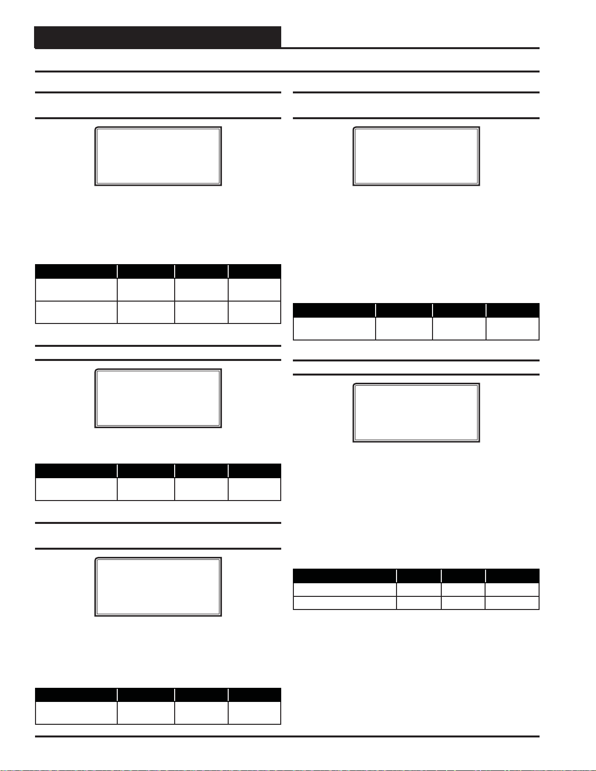
VAV/ZONE CONFIGURATION
VAV/Zone Setpoint Screens
Setpoint Screen #8 - Damper Airfl ow Night Min
and Fan On Min
XX Box Spts IDXXXX
Damper/Airflow Spt
Night Min.: XXX %
Fan On Min.: XXX %
The Night Min is the position the damper will move to when the
system is in Override Mode and this particular damper is not part
of the override group. This Night Min position only affects non-fan
powered boxes. The Fan On Min is the minimum damper or airfl ow
setting used to activate the parallel fan if installed. Pressure Independent = CFM. Pressure Dependent = %.
Description Minimum Default Maximum
Night Min 0% or
0 CFM
Fan On Min 0% or
0 CFM
0% or
0 CFM
25% or
250 CFM
100% or
9999 CFM
100% or
9999 CFM
Setpoint Screen #9 - Damper Airfl ow Reheat Min
XX Box Spts IDXXXX
Damper/Airflow Spt
Reheat Min.: XXX %
The Reheat Min is the damper or airfl ow setting used during the
Space Reheat Mode of operation.
Description Minimum Default Maximum
Reheat Min 0% or
0 CFM
0% or
0 CFM
100% or
30000 CFM
Setpoint Screen #10 - Damper Airfl ow Fixed
Position
XX Box Spts IDXXXX
Damper/Airflow Spt
Fixed Pos: XXX %
Setpoint Screen #11 - SAT HV AC Mode
Deadband
XX Box Spts IDXXXX
SAT HVAC Mode
Deadband.: XXºF
If the supply air temperature is above the space temperature by this
amount, the VAV/Zone controller enters the Supply Air Heating
Mode. It will remain in the Supply Air Heating Mode until the supply
air drops to 2ºF above the space temperature. At that point the unit
enters the Supply Air Vent Mode and remains there until the supply
air drops this deadband below the space temperature. At that point
the VAV/Zone Controller enters the Supply Air Cooling Mode and
will remain there until the supply air temperature rises to 2ºF below
the space temperature.
Description Minimum Default Maximum
SAT HVAC Mode
Deadband
0ºF 10ºF 20ºF
Setpoint Screen #12 - Zone Alarm Offsets
XX Box Spts IDXXXX
Zone Alarm Offsets
Hi Zone......: XXºF
Lo Zone......: XXºF
The VA V/Zone Controller can be setup to generate an alarm anytime
the box goes into the Occupied Mode and the Zone T emperature exceeds the user-defi ned alarm limits for a user-defi ned period of time.
A High T emperature Alarm Setpoint is created by adding the Hi Zone
Alarm offset to the current Cooling Setpoint. The Low T emperatur e
Alarm Setpoint is created by adding the Lo Zone Alarm of fset to the
current Heating Setpoint. If the zone temperature exceeds either of
these limits for a period defi ned by the Alarm Delay setpoint, the
controller can generate an alarm callout if all the optional hardware
components required for this to occur are installed.
Description Minimum Default Maximum
Hi Zone Alarm +1ºF +30ºF +50ºF
Lo Zone Alarm -1ºF -30ºF -50ºF
Many times while troubleshooting a system, it is useful to have the
zone damper set to a specifi c damper position or airfl ow setting. This
setpoint can be used to determine where the damper/airfl ow will
remain when the VAV/Zone Controller receives a Force to Fixed
Position command.
Description Minimum Default Maximum
Fixed Pos 0% or
0 CFM
0% or
0 CFM
100% or
9999 CFM
74
VCC-X Operator Interface SD
Page 75
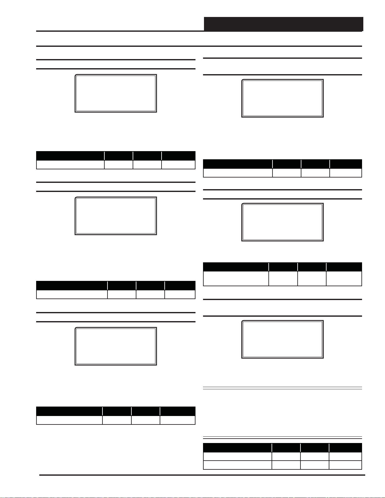
VAV/ZONE CONFIGURATION
VAV/Zone Setpoint Screens
Setpoint Screen #13 - Zone Alarm Delay
XX Box Spts IDXXXX
Zone Alarm Delay
Must Be Out Of
Limits For.: XXX Min
As mentioned above, if you confi gure the controller to generate zone
temperature alarms, this is the amount of time after the box goes into
the Occupied Mode that the temperature must be outside the alarm
limits before an alarm is generated.
Description Minimum Default Maximum
Out of Limits 1 Min 30 Min 300 Min
Setpoint Screen #14 - Day/Night Schedule
XX Box Spts IDXXXX
Day/Night Schedule
Control #: X
0=AHU 1-5=Scheduler
Setpoint Screen #16 - Push-Button Override
Duration
XX Box Spts IDXXXX
Push-Button Override
Duration : X.X Hr
If the Flush Mount W all Sensor has the optional Push-Button Over ride, this is the amount of the VA V/Zone Controller will resume using
its Occupied Setpoints during unoccupied mode. This will generate a
call for the Air Handler to start its fan and provide heating or cooling,
depending on how you confi gure the Air Handler.
Description Minimum Default Maximum
Duration 0.0 Hr 0.0 Hr 8.0 Hr
Setpoint Screen #17 - Maximum EMS Offset
XX Box Spts IDXXXX
Maximum EMS Setpoint
Offset...: XXºF
This screen allows you to set the VAV/Zone controller to operate
on a remote schedule instead of the schedule that is contained in
the VCC-X controller.
Enter <1-5> to use an external schedule. A GPC Plus is required for
Enter <0> to operate on the AHU schedule.
schedules 1-5.
Description Minimum Default Maximum
Schedule Control Number 0 0 1 to 5
Setpoint Screen #15 - Maximum Slide Offset
XX Box Spts IDXXXX
Maximum Slide Offset
Effect on Spt.: XºF
If the Flush Mount Wall Sensor has the optional Setpoint Slide
Adjust, this is the maximum amount you can adjust the heating and
cooling setpoints up or down as the slide is moved from the center
position to its full up or down position.
Description Minimum Default Maximum
Effect on SP 0ºF 0ºF 6ºF
If the Energy Management System (EMS) is activated, the heat and
cool setpoints can be spread apart by this amount.
Description Minimum Default Maximum
Maximum EMS Setpoint
Offset
0ºF 0ºF 30ºF
Setpoint Screen #18 - Sensor Calibration for
Space Temp and Supply Air Temp
Sensor Calibration
SPC: XXX.Xº XXX.Xº
SAT: XXX.Xº XXX.Xº
[SAT Only if Sensor]
The Thermistor Type III sensor readings can be calibrated. Enter a
Positive value to increase a reading and a Negative value to decrease
a reading.
Note: The Supply Air Temperature calibration offset only
operates on the reading when the VA V/Zone Controller
has its own Supply Air Temperature sensor installed on
the AUX2 input. If the supply temperature is received
from a global broadcast, you will need to go to the air
handler to calibrate the temperature reading.
VCC-X Operator Interface SD
Description Minimum Default Maximum
SPC (Space Temp) -100ºF 0ºF +100ºF
SAT (Supply Air) -100ºF 0ºF +100ºF
75
Page 76

VAV/ZONE STATUS
VAV/Zone Status Screens
VAV/Zone Status
Status Screen #1 - Mode of Operation
XX Box v4.01 IDXXXX
Occupied Mode
Vent Mode
Belongs to Group # 1
Line 2 Unoccupied Mode
Occupied Mode
Override Mode
Override Pending*
Damper Calibration
Group Override
Line 3 OFF Mode
Vent Mode
Cooling Mode
Heating Mode
Sensor Fail Mode**
Line 4 Belongs to Group # xx
No Group Affi liation
Status Screen #3 - Slide Offset & H/C Demand
XX Box v4.01 IDXXXX
Slide Offset: XXºF
H/C Demand.: XX.XºF
Line 2 If the optional Setpoint Slide Adjust is installed
on the Flush Mount Wall Sensor, this line will
display the current amount the Slide Offset is
affecting the Heating and Cooling Setpoints.
Line 3 Current Heating or Cooling Demand in the Zone
based on the current Heating and Cooling
Setpoints when compared to the current Zone
Temperature.
Line 4 Blank
Status Screen #4 - Supply Air Temperature &
Box Air Temperature
XX Box v4.01 IDXXXX
Supply Air: XX.XºF
Box Air..: XX.XºF
* Not displayed when using a Digital Room Sensor.
** Displays for either a temperature sensor failure or an
airfl ow sensor failure.
Status Screen #2 - Zone Temperature and
Cooling/ Heating Setpoints
XX Box v4.01 IDXXXX
Zone Temp..: XX.XºF
Cooling Spt: XX.XºF
Heating Spt: XX.XºF
Line 2 Current Zone Temperature
Line 3 Currently active Cooling Setpoint based on
the current Occupied / Unoccupied mode of
operation.
Line 4 Currently active Heating Setpoint based on
the current Occupied / Unoccupied mode of
operation.
Line 2 Current Supply Air Temperatur e received via
broadcast from the DX Air Handler or from the Box
Controller’s own installed Box Air Temperature
Sensor connected to the AUX input of the VAV/
Zone controller board.
Line 3 Current Box Air Temperature
If you have confi gured the VCC-X controller to
broadcast the Supply Air Temperature to the VAV/
Zone controller and don’t have a Box Air
Temperature Sensor attached to the AUX input
on the VAV/Zone controller board, this line will
display the Supply Air Temperature the same as
line 2.
If you have a Box Air Temperature Sensor
attached to the AUX input on the VAV/Zone
controller board, this line will display the Box Air
Temperature at the location where the Box Air
Temperature Sensor is installed.
Line 4 Blank
76 VCC-X Operator Interface SD
Page 77

VAV/ZONE STATUS
VAV/Zone Status Screens
Status Screen #5 - Zone Damper Position,
Airfl ow, and Desired CFM
XX Box v4.01 IDXXXX
Damper FRC: XXX %
Airflow : XXXX CFM
Desired : XXXX CFM
Line 2 Current Zone Damper Position
If you entered a FORCE command, the letters FRC
will appear. If this is normal damper operation, the
FRC will not be displayed.
Line 3 If this is a Pressure Independent box, the current
Airfl ow will be displayed. If not, this line will
display the desired damper position.
Line 4 If this is a Pressure Independent box, this line will
display the Desired CFM the box would like to
provide to the zone. If not, this line will display
[Controls to +/- 3%] to indicate how accurately the
damper will maintain the desired position.
Status Screen #6 - Fan Status & Reheat
Stages
XX Box v1.04 IDXXXX
Fan Status : OFF
Heating Relay#1 : OFF
Heating Relay#2 : OFF
Line 4 If your VAV/Zone Controller has been confi gured
to control reheat stages, this line refl ects the On/Off
Status of the second stage of Reheat. If you have 3
stages of reheat as explained on line 2, this line will
be blank.
Status Screen #7 - Alarm Status
XX Box v1.04 IDXXXX
NO ALARMS!
XX Box v.104 IDXXXX
ALARMS PRESENT
SCROLL DOWN TO VIEW
Line 2 Blank
Line 3 NO ALARMS! OR ALARMS PRESENT
If there are one or more alarms active, the possible
messages are shown below:
SPACE SENSOR FAILURE
CFM SENSOR FAILURE
DAMPER OPENING ALARM
Line 2 If this is a Fan Powered box, this line will display
the Fan On/Off Status. On non-fan powered boxes,
this line will display [Exp Relay 1 Not Used].
Line 3 If your V AV/Zone Controller has been confi gured to
control reheat stages, this line refl ects the On/Off
Status of the fi rst stage of Reheat. If you have 3
stages of reheat, this line will display the total
number of active heating stages.
Examples:
“1 Reheat Stages On” or
“2 Reheat Stages On” or
“3 Reheat Stages On”
If proportional heating is used (you have no relays
confi gured for heat), this line will display
“Heating Signal: xxx %”.
DAMPER CLOSING ALARM
HI SPACE TEMP ALARM
LO SPACE TEMP ALARM
DPR FEEDBACK FAILURE
Press <> to scroll through all active alarms.
For Alarm Defi nitions, see the VCC-X Controller
Technical Guide.
VCC-X Operator Interface SD
77
Page 78

VAV/ZONE DAMPER FORCE
VAV/Zone Damper Force Modes
Damper Force Modes
Damper Force Modes are available for testing or balancing the system. These Force Modes can be accessed and programmed from
the Modular Service Tool.
Modular Service Tool Instructions
When using the Modular Service Tool, simply press the <BAL-
ANCE - TEST>
unit ID of the controller you wish to access and
Once communication is established, the *00* message will go away.
press <>.
Then
NOTE: If the *00* remains, it indicates a communication
The following screen will be displayed:
With the cursor on Damper Force, press <ENTER> to access the
Damper Force Mode Screen.
Dampers Force Mode Screen
If the unit ID you entered is for a VCC-X Controller that has VAV/
Zone Controllers connected to its communication loop, the Damper
Force Mode will act as a “Global” Damper Force Mode. That is, all
VA V/Zone Controllers on that VCC-X Controller’ s communication
loop will be forced to the same Damper Force Mode setting. If the
unit ID you entered is for a VA V/Zone Controller , the Damper Force
Mode setting will only apply to that VAV/Zone Controller.
key. You will then see the Unit ID Screen. Enter the
press <ENTER>.
failure to the controller.
Damper Force
Para Blocks
Load / Save / Copy
Set the appropriate Damper Force Mode by entering numbers 0
through 5. Following is a list of the force modes and their meaning:
0 = Auto This is the default setpoint. With this setting,
the damper will operate normally and modulate
according to the controller setpoints.
1 = Open This setting will force the dampers to their
fully-open position.
2 = Clsd This setting will force the damper to its fully-
closed position.
3 = Max This setting will force the damper to its
Maximum Position Setpoint. See VAV/Zone
Controller Setpoint Screen #5 on page 73 for
complete setpoint information.
4 = Min This setting will force the damper to its
Minimum Position Setpoint. See
Controller Setpoint Screen #5
complete setpoint information.
5 = Fixed This setting will force the damper to a fi xed
position based on the Fixed Position Setpoint.
See
on page 74 for complete setpoint information.
CAUTION: The Damper Force Modes should only be used
by qualifi ed service personnel. Serious dam-
age to the ductwork could result if the dampers
are all forced closed and the HVAC unit fan
is operating.
VAV/Zone Controller Setpoint Screen #8
VAV/Zone
on page 73 for
Damper Force
Enter Force Mode: 0
0=Auto 1=Open 2=Clsd
3=Max 4=Min 5=Fixed
VCC-X Operator Interface SD78
Page 79
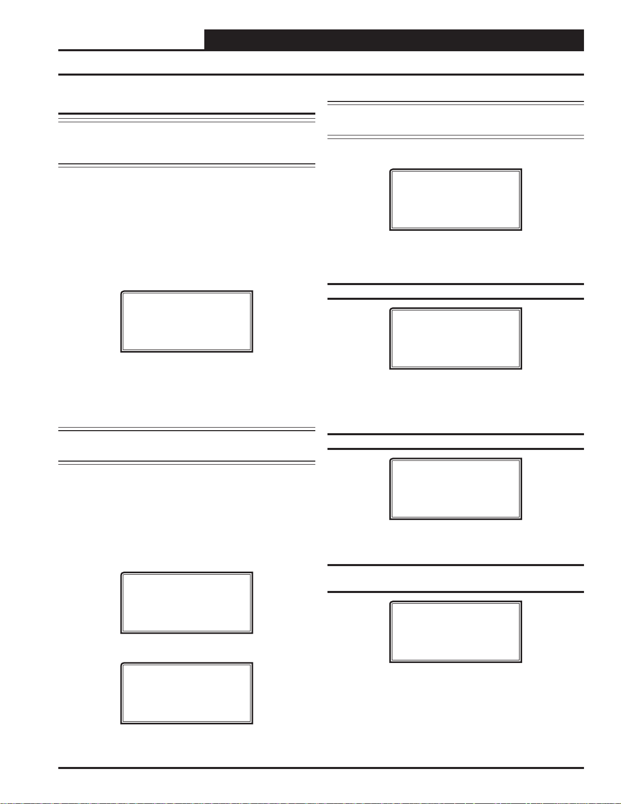
MINILINK PD CONFIGURATION
MiniLink PD Confi guration Screens
MiniLink PD Confi guration
NOTE: If this is not a voting system, the only screens you
need to confi gure are Screens 6 through 65 if alarm
polling pertains to your system.
In order to correctly setup the MiniLink PD, you must fi rst confi gure
several parameters in regard to the type of system and operating
parameters for the system it is installed on. Most of these values
and operating parameters are only set once at the initial system setup
and are never changed.
Modular Service Tool Instructions
From any menu screen, press <SETPOINTS>. The Unit Selection
Screen, shown below,
ID number.
All MiniLink PDs are set at address 60. Enter the correct unit loop
number for the loop the MiniLink Polling Device is connected to
(for Loop 1 you would enter <160>) and press <ENTER>. Once
communication is established, the *00* message will go away. Then
press <>.
will appear requesting that you enter the unit
Enter Unit Address
Then Press Enter
Selected Unit #_1
Press Down
NOTE: If the *00* remains, it indicates a communication
failure to the controller.
The following screen will be displayed:
Change Setpoints
Configure Unit
Save/Copy/Restore
Scroll to the ‘Change Setpoints’ option and press <ENTER>. This
will take you to the fi rst Setpoints Screen shown below.
Confi guration Screen #1 - System Type
Polling Unit Config
System Type
Selection: ZONING
Use < Or > To Change
This screen allows you to select whether you want the system to
behave as a VA V system or a Zoning System. If you select VAV, this
will allow tenant logging for your VAV system.
NOTE: If the *00* remains, it indicates a communication
failure to the controller.
You will then see Setpoint Screen #1. Press
tered data and
press <> to scroll through the screens.
<ENTER> to save en-
System Manager SD Instructions
From any Main screen, press <SETPOINTS>. The screen below
will appear because this option requires passcode clearance. Only a
Level 2 passcode can change setpoints.
THIS ACTION REQUIRES
PASSCODE CLEARANCE
Enter Passcode: XXXX
If the correct passcode was entered, the Unit Selection Screen will
be displayed.
Enter Unit Address
Then Press Enter
Selected Unit #_1
Press Down
Enter the Unit ID of the controller you wish to change schedules for
and
press <ENTER>. Once communication is established, the *00*
message will go away. Then
press <>.
Confi guration Screen #2 - Last Polled Zone
Polling Unit Config
Last Polled Zone
Address: XX
[Enter Last Zone]
This zone is the last zone on the local loop of your zoning system
that is to be included in zone voting.
Confi guration Screen #3 - Mode Changeover
Time
Polling Unit Config
Mode Changeover Time
Minutes: XX
[Enter Period Time]
This is the amount of time that you want to allow between changeover
from heating to cooling modes.
VCC-X Operator Interface SD
79
Page 80

Zone
MINILINK PD CONFIGURATION
MiniLink PD Confi guration and Status Screens
Zone
Confi guration Screen #4 - Optimal Start
Target Zone
Polling Unit Config
Optimal Start
Target Zone..: XXX
[Enter Target Zone]
This is the unit ID of the Zone that you want to be satisfi ed by the
normally scheduled start time. If you enter “-1” into this box, it will
average all zones instead of picking a specifi c zone. If you do not
require Optimal Start, enter “0”.
Confi guration Screen #5 - Maverick Testing
Polling Unit Config
Maverick Testing
Disabled: YES
Use < Or > To Change
Disabling the Maverick Testing allows known troubled zone(s) to
continue voting without causing a Maverick alarm. In other words,
all zones are included in the voting regardless of whether they are
more than four degrees from setpoint.
Confi guration Screens #6-65 - Alarm Polling
MiniLink PD Status
Status Screen #1 - Schedule Mode, System
Status, and Minutes Left
Polling Device
System Occupied
Venting Mode
XXX Min Left in Mode
Line 2 Current Schedule Mode
Can be System Occupied or System Unoccupied.
Line 3 Currently System Status
Can be Vent Mode, Cooling Mode, or Heat Mode.
Line 4 Minutes Left In Mode
The number of minutes left in the current mode of
operation before it can switch modes. This value is
user-adjustable. See Confi guration Screen #3.
Status Screen #2 - Mode Priority, Cool Total,
and Heat Total
Polling Device
No Mode Priority
Cool Total.: XX.XºF
Heat Total.: XX.XºF
Polling Unit Config
Enable Alarm Polling
Unit XX : YES
Use < Or > To Change
Enabling Alarm Polling allows any alarm from the loop to be polled.
You must set this for each controller on the loop.
Line 2 Mode Priority
Can be Heat Priority or Cool Priority. This is based
on the voting zones and their demand.
Line 3 Cool Total
Total cooling temperature demand from all zones.
Line 4 Heat Total
Total heating temperature demand from all zones.
80
VCC-X Operator Interface SD
Page 81

TROUBLESHOOTING
VCC-X Outputs Force
Outputs Force
Outputs Force settings are available for testing or troubleshooting the
system. These Force settings can only be accessed and programmed
from the Modular Service Tool.
CAUTION: The Outputs Force settings should only be
applied by qualifi ed service personnel.
Serious damage to the HVAC unit could
result from improper use of these Outputs
Force settings.
To access the Outputs Force settings, simply
- TEST>
button on the Modular Service Tool. You will then see
the Unit ID Screen.
Enter Unit Address
Then Press Enter
Selected Unit #_1
Press Down
Enter the unit ID of the VCC-X Controller you wish to access and
press <ENTER>. Once communication is established, the *00* mes-
sage will go away. Then
shown below. Press
press <>. You will then see the screen
<ENTER> to save entered data and press <>
to scroll through the screens.
press the <BALANCE
The next screen displays the Relay Overrides for Relay 2. After
pressing <ENTER> to save any changes, press <> to have the
next relay displayed. All 23 Relay Override Screens (including the
AHU fan relay) are available by
saved by pressing
<ENTER> .
Relay Overrides
Relay 2 Override
Auto
Use < Or > To Change
pressing <> after each setting is
After the screen for relay 23 is displayed, the fi rst Analog Output
Override Screen
will be displayed.
Analog Output 1 Screen
Main Fan VFD
Override Volts: -1.0
[-1.0 = Auto]
The default setting for normal operation is -1.0 volts. Voltages
between 0 to 10.0 are valid entries. Press <ENTER> after making
a setting change and then
Override Screen
will be displayed.
press <> and the next Analog Output
NOTE: If the *00* remains, it indicates a communication
failure to the controller.
NOTE: The Outputs Force settings are only available for the
VCC-X Controller. They are not supported for the
VAV/Zone Controllers or other Add-on controllers.
Outputs Force
Para Blocks
Save / Load / Copy
Place the cursor on Outputs Force and press <ENTER> to access the
Outputs Force Screen.
Supply Fan Override
Auto
Use < Or > To Change
The fi rst Outputs Force Screen allows the AHU fan relay to be set
for Auto, Force On, or Force Of f. The default setting is Auto. After
you complete all troubleshooting or testing procedures, all relays
should be changed back to this setting. The Force On setting will
force the relay to the ON (energized) position. The Force Off selection will force the relay to the OFF (de-energized) position.
Analog Output 2 Screen
Economizer
Override Volts: -1.0
[-1.0=Auto]
The default setting for normal operation is -1.0 volts. Voltages
between 0 to 10.0 are valid entries. Press <ENTER> after making
a setting change and then
Override Screen
will be displayed.
press <> and the next Analog Output
Analog Output 3 Screen
Modulating Heat
Override %...: -10%
[-10 = Auto]
The default setting for normal operation is -10 %. Percentages
between 0 to 100 are valid entries.
a setting change and then
Override Screen
will be displayed.
press <> and the next Analog Output
Press <ENTER> after making
VCC-X Operator Interface SD
81
Page 82

TROUBLESHOOTING
VCC-X Outputs Force
Zone
Zone
Analog Output 4 Screen
Exhaust Fan Signal
Override Volts: -1.0
[-1.0 = Auto]
The default setting for normal operation is -1.0 volts. Voltages
between 0 to 10.0 are valid entries.
a setting change and then
Override Screen
The default setting for normal operation is -10%. Percentages
between 0 to 100 are valid entries. Press <ENTER> after making
a setting change and then
Override Screen
will be displayed.
will be displayed.
press <> and the next Analog Output
Analog Output 5 Screen
Modulating Cool
Override %...: -10%
[-10 = Auto]
press <> and the next Analog Output
Press <ENTER> after making
Analog Output 6 Screen
Mod Condenser
Override Volts: -1.0
[-1.0 = Auto]
The default setting for normal operation is -1.0 volts. Voltages
between 0 to 10.0 are valid entries.
a setting change.
Press <ENTER> after making
82
VCC-X Operator Interface SD
Page 83

APPENDIX A - SAVE, LOAD, COPY SETPOINTS
Saving & Copying Setpoints
Modular Service Tool Instructions
From any menu screen, press <BALANCE-TEST>. The Unit Selec-
tion Screen
will appear requesting that you enter the unit ID number.
Enter Unit Address
Then Press Enter
Selected Unit #_1
Press Down
Enter the network unit ID for the controller you want to save the
setpoints from. Example, ‘102’ for Loop 1 / Unit 2. Then press
<ENTER>. Once communication is established, the *00* message
will go away. After a brief pause, press
<> to get to the Balance
- Test Screen shown below.
Outputs Force
Para Blocks
Save/Copy/Restore
Scroll down to the ‘Save/Copy/Restore’ option and press <ENTER>.
This will take you to the Save Setpoints screen.
NOTE: If the *00* remains, it indicates a communication
failure to the controller.
The following screen will be displayed:
Change Setpoints
Configure Unit
Save/Copy/Restore
Scroll down to the ‘Save/Copy/Restore’ option and press <ENTER>.
This will take you to the Save Setpoints screen.
Save Setpoints - Network Mode
From the Save Setpoints Screen shown below:
Save Setpoints
Press Enter To Save
System Manager SD Instructions
From any Main screen, press <SETPOINTS>. The screen below
will appear because this option requires passcode clearance. Only a
Level 2 passcode can change setpoints.
THIS ACTION REQUIRES
PASSCODE CLEARANCE
Enter Passcode: XXXX
If the correct passcode was entered, the Unit Selection Screen will
be displayed.
Enter Unit Address
Then Press Enter
Selected Unit #_1
Press Down
Enter the Unit ID of the controller you wish to save the setpoints
from and press
*00* message will go away. Then
<ENTER>. Once communication is established, the
press <>.
Press <ENTER> and a setpoint fi le will be saved to the SD card.
You will receive a message that the save was successful. This fi le
is specifi c to this controller on this loop.
VCC-X Operator Interface SD
83
Page 84

APPENDIX A - SAVE, LOAD, COPY SETPOINTS
Copying & Restoring Previously Saved Setpoints
Copy Setpoints - Network Mode
To copy a saved setpoints fi le to other controllers on the network
do the following:
From the Save Setpoints Screen shown below:
Save Setpoints
Press Enter To Save
Press <> once to access the Copy Setpoints Scr een shown below .
Copy Setpoints
From Loop 1
From Unit 2
Press Enter to Copy
In the ‘From Loop’ fi eld, enter the Loop of the controller you want
to copy the setpoints from. In this example it is ‘1’. Then press
<ENTER>.
In the ‘From Unit’ fi eld, enter the Unit ID of the controller you
want to copy the setpoints from. In this example it is ‘2’. Then
press
<ENTER>.
Restore Setpoints - Network or
Stand-Alone Mode
The Restore Setpoints feature is used to reload a saved setpoints fi le
from one controller back to itself. This could be useful if setpoints
or confi gurations were changed and need to be reset.
Y ou can perform this function on a networked system; however , the
Modular Service T ool needs to be directly connected to the controller
you wish to restore previously saved setpoints to.
From the Save Setpoints Screen shown below:
Save Setpoints
Press Enter To Save
Press <> four times to access the Restor e Setpoints Screen shown
below.
Restore Setpoints
Press Enter to Load
Now your cursor will be on the last line, and you can
once more to copy the setpoint fi le from unit 102 to unit 103.
You will receive a confi rmation that the copy was successful.
press <ENTER>
Save & Copy Setpoints - Stand-Alone
Mode
The instructions for Stand-Alone Mode are exactly the same as
Network Mode, except that there is no need to enter a Loop number
in the Unit ID number fi eld and in the Copy Setpoints Screen, enter
a zero in the ‘From Loop’ fi eld.
Press <ENTER>. This will reload the setpoints from the saved fi le.
You will receive confi rmation that the setpoints were loaded suc-
cessfully.
84
VCC-X Operator Interface SD
Page 85

APPENDIX B - UPDATING THE SD CARD
SD Memory Card Update
Updating Your SD Memory Card
You may need to update your SD memory card from time to time,
either for a new release or to add data for another Controller.
Follow the instructions below to download the update fi le from
our tech support webpage:
1. Insert the SD memory card in your computer’s SD drive
and open the drive’s window.
2. Open your browser and type in the address:
http://wattmaster.com/techsupport.
3. On the Tech Support webpage, locate the fi le
Modular_HH_Screens.zip and double-click on it.
4. Click
<Save File> when asked to save or open the fi le
and then click <OK>. This option will save the fi le to the
“Downloads” folder on your PC.
6. Once you unzip the fi le, you will see a window similar
to the one below.
7.
Press <CTRL> <A> to highlight the folders in the
window—App, Manuals & Scr. Press <CTRL> <C> to
copy the folders.
5. Open the “Downloads” folder in Windows Explorer. You
will fi nd a folder labeled, “Modular_HH_Screens.zip.”
Right-click on this folder and choose “Extract All” from
the options list. NOTE: Any compression software can
be used to extract the zip folder’s contents, for example,
Winzip.
8. Paste the fi les into the SD memory card drive’s window
by pressing
9. Remove the SD Memory Card from your computer and
reinsert it in the Modular Hand Held Service Tool or
Modular System Manager.
<CTRL> <V>.
VCC-X Operator Interface SD
85
Page 86

APPENDIX C - UPDATING CONTROLLERS & MODULES
Updating Controller & E-BUS Module Software
Updating Controller & E-BUS Module
Software Using the Modular Service
Tool SD
To update the software for various WattMaster controllers and EBUS modules, follow these simple steps.
1. Update your SD memory card with the new software fi le
for the controller or module you need to update. Follow
the steps on page 85 for Updating the SD memory card.
WattMaster Controllers
1. Press <1> to update a WattMaster Controller.
The following screen will appear:
Enter Board Address
0
Esc) Exit Menu
2. Connect the Modular Service Tool to the device you
wish to update using the mini DIN communication cable
or EBC E-BUS cable provided.
3. Power up the controller or E-BUS module you wish to
update.
4. Apply power to the Modular Service Tool SD and
press the
5. After initialization of the Modular Service Tool SD,
press <NEXT> at the fi rst Setup Screen and <4> at the
second Setup Screen shown below.
6. The Update Software Screen will appear as shown
below:
<ON> button.
1) Set Time & Date
2) Communications
NEXT) More Options
ESC) Exit Menu
3) Energy Saving
4) Update Software
NEXT) More Options
ESC) Exit Menu
Select Communication
1) WattMaster Comm
2) E-BUS Module
ESC) Exit Menu
2. Enter the address of the controller you are updating and
then press
3. The Software Version Screen will appear as shown
below. Enter <0> for the latest software version or enter
the number of an older version given to you by
Technical Support. Then press
4. The screen will display the following messages:
“Resetting Unit”
“Load Sys Info”
5. If communications are successful, the screen will
display, the name of the HEX fi le on the top line,
“Flash Memory Erased” on the second line, and the
progress percentage on the third line.
NOTE: If communications are not successful, the screen
will display, “Press Any Key to Continue. Cannot Load
Sys Info.” Make sure you have the right address and the
right software version on your SD card. If these two
items are correct and you still experience a problem,
contact Technical Support.
6. When updating is complete, the screen will display,
“Finish Download.”
<ENTER>.
<ENTER>.
Software Version
Enter 0 for Latest
0
Esc) Exit Menu
7. Follow the instructions for WattMaster Controllers or
E-BUS Modules.
86
VCC-X Operator Interface SD
Page 87

APPENDIX C - UPDATING CONTROLLERS & MODULES
Updating Controller & E-BUS Module Software
E-BUS Modules
1. Press <2> to update an E-BUS Module.
The following screen will appear:
Enter Board Address
0
Esc) Exit Menu
2. Enter the address of the E-BUS module you are updating
and then press <ENTER>. The following is the list of
Module addresses:
MHGRV-X - address 132
MODGAS-X - address 138
PREHEAT-X - address 157
RSMV #1 - address 152
RSMV #2 - address 153
RSMV #3 - address 154
RSMV #4 - address 155
WSHP-X - address 17
5. If communications are successful, the screen will
display, the name of the HEX fi le on the top line,
“Flash Memory Erased” on the second line, and the
progress percentage on the third line.
NOTE: If communications are not successful, the screen
will display, “Press Any Key to Continue. Cannot Load
Sys Info.” Make sure you have the right address and the
right software version on your SD card. If these two
items are correct and you still experience a problem,
contact Technical Support.
6. When updating is complete, the screen will display,
“Finish Download.”
3 The Software Version Screen will appear as shown
below. Enter
the number of an older version if given to you by
Technical Support. Then press <ENTER>.
4. The screen will display the following messages:
“Resetting Unit”
“Load Sys Info”
<0> for the latest software version or enter
Software Version
Enter 0 for Latest
0
Esc) Exit Menu
VCC-X Operator Interface SD
87
Page 88

INDEX
A-D
12 Relay E-BUS Expansion Module
Installed.........26
12 Relay E-BUS Relay
Confi guration Screens.........37
12 Relay Expansion Module Relays.........62
24-Hour Military Format.........14,22
1111.........19
2222.........19
2359.........14,22
A
AHU Heat Call Space Temperature
VAV/Zone.........73
AHU Uses Schedule Number.........34
Airfl ow, VAV/Zone Status.........77
Airfl ow Station Type Screen.........33
Alarm Active Relay, Description.........38
Alarm Offset.........42
Alarms
Button.........10,16
Clearing.........13,21
MiniLink Polling.........20,80
Modular Service Tool.........13
VAV/Zone Status.........77
Alarms for VCC-X.........63
Alarm Status.........63
Analog Output Override Screen.........81
Application Type Status.........55
Arrow Keys Defi ned.........10,12,16,18
Auto Damper Force Mode.........78
Automatic Power Down.........12
B
Balance-Test Button Defi ned.........10
Box Air Temperature
VAV/Zone Status.........76
Box Confi guration VAV/Zone.........69
Boxes Broadcast To.........36
Box Heat Allow VAV/Zone.........70
Broadcast Building Pressure.........35
Broadcasting.........34,36
Broadcast Outdoor Air RH Screen.........35
Broadcast to Boxes.........36
Building Pressure Sensor Installed.........31
Building Pressure Deadband Setpoint.........49
Building Pressure Broadcast.........35
Building Pressure Control
OA Damper.........31
Supply Fan.........31
Building Pressure Control Rate Screen.......31
Building Pressure Control Screen.........31
Building Pressure Exhaust Fan.........60
Building Pressure & Setpoint.........60
Building Pressure Setpoint & Deadband.....48
Bypass Damper Signal.........61
C
Calibration
Space Sensor Calibration.........52
Celsius.........25
Change Passcodes.........19
Chilled W ater.........29
Clear Alarms.........13,21
Clear Key Defi ned.........10,16
Closed
Damper Force Mode.........78
CO
Altitude Setpoint.........48
2
CO2 Level.........59
CO
Protection Limit Max Level.........48
2
CO
Sensor Calibration.........53
2
CO2 Sensor Confi guration Screen.........31
Sensor Installed.........31
CO
2
CO2 Setpoints Min/Max.........48
CO
Setpoints Status.........59
2
Coil (Saturation) Temp.........67
Coil Setpoint.........67
Coil (Suction Line) Temperature 1.........68
Coil (Suction Line) Temperature 2.........68
Coil Suction Pressure.........67
Coil Temperature Setpoint.........43
Communications Screen.........12,18
Communication Timeout Alarm.........68
Compressor 1 & 2 Enable.........67
Compressor 1 Trip Alarm.........68
Compressor 2 Trip Alarm.........68
Compressor Current Position.........67
Compressor Settings.........66
Condenser Fan Signal.........68
Confi guration.........69
12 Relay E-BUS Expansion
Module.........26
Button.........10
EM1 Expansion Module.........26
Fan Voltage Output.........28
MHGRV-X.........26
MODGAS-X.........26
PREHEAT-X.........26
RSM Module.........25,26
Screen Index.........24
Connection Diagram
Modular Service Tool.........5
Continuous OFF Mode.........14,22
Continuous ON Mode.........14,22
Controlling Sensor High/Low Alarm
Offset.........42
Cooldown SAT Setpoint.........51
Cool/Heat Stage Delays.........36
Cooling Active Stages Status.........56
Cooling Enabled Status.........56
Cooling Enabled Status Screen.........56
Cooling Min Off Time.........36
Cooling Min Run Time.........36
COOLING ONLY BOX, VAV/Zone.........69
Cooling Setpoints, VAV/Zone Status.........76
Cooling Setpoints Status.........55
Cooling Stage Relay Description.........38
Cooling Unoccupied Offsets.........41
Cool Reset Source Setpoints - High Reset/
Low Reset.........44
Cool Total MiniLink PD Status.........80
Copy Setpoints.........84
Current Active Supply Air Setpoint.........56
Current Supply Air Temperature.........56
D
Damper Airfl ow
Cool/Heat Minimum.........73
Fan On Min.........74
Fixed Position.........74
Integral.........73
Maximum.........73
Night Minimum.........74
Reheat Minimum.........74
Vent Minimum.........73
Damper Force Modes.........78
Damper Operation VAV/Zone.........69
Dampers Forced Closed.........78
Data Entry Keys Described.........10,16
Date, Programming.........11,17
Date and Time Status Screen.........55
Daylight Savings Adjustment.........35
Day/Night Schedule VAV/Zone.........75
Deadband, Static Pressure.........43
DEC Key Defi ned.........10,16
Defrost Heat Wheel Setpoint.........50
Dehumidifi cation Control Screen.........32
Desired CFM VAV/Zone Status.........77
Dewpoint.........30
Dewpoint Setpoint.........42
Dimensions
Modular Service Tool.........4
System Manager.........6
Direct Acting Building Pressure
Control.........32
Direct Acting Control.........48
Dirty Filter Screen.........35
Display Screen Described.........10,16
Drybulb.........30
Duct Static Pressure Output Signal
Percentage Status.........60
Duct Static Pressure Setpoint.........60
Duct Static Pressure Setpoint Status.........60
Duct Static Pressure Status.........60
Dump Zone, VAV/Zone.........71
VCC-X Operator Interface SD88
Page 89

INDEX
E-M
E
Economizer
Maximum Position if High CO
Setpoint.........48
Overrides.........81
Economizer %.........59
Economizer Active Relay Description........38
Economizer Control Loop Rate.........30
Economizer Control Type.........30
Economizer Enabled.........59
Economizer Enable Setpoint.........47
Economizer Enable Source Screen.........30
Economizer in IAQ Mode.........59
Economizer in Unoccupied Mode.........30
Economizer Minimum Damper
Position.........47
Economizer Minimum Position.........59
Economizer Voltage Output.........31
EM1 Installed.........26
EM1 Relay Confi guration Screens.........37
EM1 Relays.........62
Emergency Shutdown.........35
Energy Saving Timer.........12
Enter
Key.........10,16
New Passcode.........19
ESC Key Defi ned.........10,16
Return Air Relative Humidity
Percentage.........57
Exhaust Air CFM.........60
Exhaust Airfl ow Duct Size.........34
Exhaust Airfl ow Monitoring.........34
Exhaust Fan Output Screen.........32
Exhaust Fan Relay Description.........38
Exhaust Fan Status.........60
Exhaust Fan VFD.........48
Exhaust VFD Override.........82
Expansion Relays Heating Stages
VAV/Zone.........70
Expansion Valve 1 Position.........68
Expansion Valve 2 Position.........68
Level
2
F
Fahrenheit.........25
Fan Cycle Mode Screen.........28
Fan On Min.........74
Fan Proving Screen.........28
Fan Starting Delay Screen.........29
Fan Status.........77
Fan VFD Signal.........27
Fan Voltage Output Screen.........28
Fixed Damper Force Mode.........78
Fixed Position Damper Airfl ow.........74
H
H/C Changeover Box VAV/Zone.........69
Head Pressure Setpoint.........68
Head Pressure Setpoints - Cooling and
Reheat.........47
Heat/Cool Changeover Delay.........36
Heating
Min Off Time.........36
Min Run Time.........36
Setpoints.........76
Stage Down.........36
Stage Up.........36
Heating Active Stages Status.........57
Heating/Cooling Demand
VAV/Zone Status.........76
Heating Enabled Status.........56
Heating Outputs.........57
Heating Setpoints Status.........55
Heating Stage Relay Description.........38
Heating Unoccupied Offsets.........41
Heat Reset Source Setpoints - High/
Low Reset.........45
Heat Total
MiniLink PD Status.........80
Heat Type Screen.........29
Heat Wheel Defrost Temperature
Setpoint.........50
Heat Wheel Relay Description.........38
High Head Pressure Alarm.........68
Hi SAT Cutoff.........49
Holidays
Programming.........14
Start/Stop Times.........15,23
Hood On HVAC Setpoints.........40
Humidity Control Sensor Type.........32
HVAC Cool/Heat Setpoints.........40
HVAC Hood On Setpoints.........40
HVAC Mode
Cooling Setpoints.........40,41
Heating Setpoints.........40,41
Unoccupied Offsets.........41
HVAC Mode Deadband.........41
HVAC Mode Set By Remote Contact.........27
HVAC Mode Status.........55
HVAC Source Screen.........26
I
IAQ Economizer.........30
Indoor Relative Humidity Setpoint
Percentage.........57
Indoor RH.........57
Indoor RH Setpoint.........43
Initialization Screen.........11,17
K
Keys Described.........10,16
L
Last Polled Zone MiniLink PD.........79
Leaving Air Temperature Setpoint.........57
Level 1 & Users Defi ned.........19
Loop Search.........20
Low Ambient Relay Description.........38
Low Ambient Setpoint.........50
Low Suction Pressure Alarm.........68
Low Superheat 1 Alarm.........68
Low Superheat 2 Alarm.........68
M
Main Fan Status VAV/Zone.........70
Maverick Testing MiniLink PD.........80
Max Adjust Static Pressure Control
Rate.........28
Maximum
Damper Force Mode.........78
EMS Offset VAV/Zone.........75
Slide Offset VAV/Zone.........75
Maximum Economizer Position in Heat
Mode.........47
Maximum Outdoor Air CFM.........47
Mechanical Heat/Cool Alarm Delay.........30
MHGRV-X Enabled Status.........57
MHGRV-X Installed.........26
MHGRV-X Reheat Valve Output Signal
Percentage Status.........57
Min Damper Force Mode.........78
MiniLink PD Confi guration.........79
Alarm Polling.........80
Last Polled Zone.........79
Maverick Testing.........80
Mode Changeover Time.........79
Optimal Start Target Zone.........80
System Type.........79
MiniLink PD Status
Adding Additional.........20
Cool Total.........80
Heat Total.........80
Minutes Left.........80
Mode Priority.........80
Schedule Mode.........80
System Status.........80
Minimum Outdoor Air CFM.........47
Minimum Outdoor Airfl ow.........47
Minimum Run Times and Off Times.........36
Minus Key Defi ned.........10,16
Minutes Left, MiniLink PD Status.........80
Mod
Cooling Override.........82
Heating Override.........81
VCC-X Operator Interface SD
89
Page 90

INDEX
M-R
Mod Cool Enable Relay Description.........38
Mod Cool Proportional Window and Time
Period.........46
Controlling Sensor High Alarm
Offset.........42
Mode
Changeover Time.........79
of Operation.........12,18,76
Priority.........80
Selection Buttons Defi ned.........10,16
MODGAS-X Enabled Status.........57
MODGAS-X Heating Output Signal
Status.........57
MODGAS-X Installed.........26
Mod Heat Enable Relay
Description.........38
Mod Heat Output Position in
Off Mode.........49
Mod Heat Proportional Window and Time
Period.........46
Mod Heat Then Staged.........29
Modular Service Tool
Alarms Button.........13
Alarm Search.........13
Connection Diagram.........5
Defi ned.........4
Dimensions.........4
Energy Saving Timer.........12
Initialization Screen.........11,17
Instructions.........40
Mode Selection Buttons.........10,16
Override Search.........13
Overrides Tool.........13
VCC-X Setpoints.........40
Modular System Manager
Connection Diagram.........7
Defi ned.........6
Dimensions.........6
Network Connection.........7
Stand-Alone Connection.........9
Modulating Chilled Water.........26,29
Modulating Cooling Output Signal Status
Percentage.........56
Modulating Exhaust Damper.........48
Modulating Gas.........29
Modulating Gas Heat.........29
Modulating Heating Output Signal
Percentage Status.........57
Modulating Heat Output Signal.........29
Modulating Hot Water.........29
Modulating SCR Electric Heat.........29
Monitor Exhaust Airfl ow.........34
Monitor Outdoor Air Airfl ow.........33
Month.........11,17
Morning Cool-Down.........36
Morning W arm Up.........34
Max Length.........50
Tar get Temp.........50
Morning W arm-Up Relay
Confi guration.........38
Morning Warm Up Setpoint.........50
Morning Warm-Up (VAV Boxes) Relay
Description.........38
Multiple MGRS.........18
N
Network Connection
Modular System Manager.........7
Night Minimum Damper Airfl ow.........74
No Coil Temperature 1 Alarm.........68
No Coil Temperature 2 Alarm.........68
No Head Pressure Alarm.........68
No Suction Pressure Alarm.........68
O
OA Damper Building Pressure Control.......31
OA Drybulb and Humidity.........58
OAT Cool Setpoint.........40
OA Temp Broadcasting.........35
OAT Heat Setpoint.........40
OAT Lockouts - Comp Cool/Comp
Heat.........49
OAT Lockouts - Heat.........49
OAT Sensor Calibration.........52
OA Wetbulb and Dewpoint.........58
Occupied
Mode.........15,23
Setpoints.........72
Occupied Active Relay Description.........38
Occupied HVAC Cool/Heat Setpoints........40
OE391-12........4
OE392-12.........6
OFF/ON Mode Continuous.........14,22
On/Off Exhaust Fan.........48
Open Damper Force Mode.........78
Optimal Start Target Zone
MiniLink PD.........80
Outdoor Air.........26
Outdoor Air Airfl ow.........59
Monitoring.........33
Outdoor Air CFM.........47,59
Outdoor Air Damper.........49
Outdoor Air Dewpoint.........58
Outdoor Air Drybulb Status.........58
Outdoor Airfl ow.........47
Outdoor Airfl ow Duct Size.........33
Outdoor Air Humidity Broadcast.........35
Outdoor Air Relative Humidity
Status.........58
Outdoor Air Temperature Sensor.........52
Outdoor Dewpoint Setpoint.........42
Outdoor Sensor Type.........27
Outputs Force.........81
Override Active Relay Description.........38
Overrides Button.........10,16
Screen.........13,21
Search.........13,21
P
PARALLEL FAN BOX, VAV/Zone.........69
Passcode
1111.........19
2222.........19
Clearance.........18
Codes.........19
Enter New.........19
System Manager.........19
Power/Comm Board Wiring.........8
Power Down.........12
Pre-Heat Relay Description.........38
Preheat Relay Setpoint.........50
PREHEA T-X Active Stages.........58
Preheat-X Cooling Setpoint.........51
PREHEAT-X Enabled Status.........57
PREHEAT-X Entering Air
Temperature.........58
Preheat-X Heating Setpoint.........51
PREHEAT-X Installed.........26
PREHEAT-X Leaving Air
Temperature.........58
PREHEAT-X Modulating Position.........58
Preheat-X Venting Setpoint.........51
Pressure Independent Airfl ow Constant
VAV/Zone.........70
Programming
Date.........11,17
Day of Week.........11,17
Holidays.........14
Holiday Start/Stop Times.........15,23
Month.........11,17
Time & Date.........11,17
Year.........11,17
Proportional Heating Signal
VAV/Zone.........70
Purge Mode Delay Screen.........29
Push-Button Override
Duration.........75
VAV/Zone.........71
R
Real Time Clock.........11,17
Refrigeration Module Cooling.........29
Reheat Stages.........77
Reheat Minimum Damper Airfl ow.........74
Reheat Relay Description.........38
Reheat Type Screen.........32
Relay
Alarm Active.........38
Confi guration Screens.........37
Overrides.........81
Relay Defi nitions.........38
Relays
Cooling Stage.........38
Economizer Active.........38
Heating Stage.........38
Low Ambient.........38
VCC-X Operator Interface SD90
Page 91

INDEX
R-S
Mod Heat Enable.........38
Occupied Active.........38
Override Active.........38
Pre-Heat.........38
Remote HVAC Mode.........27
Remote Signal Contact.........14,22
Remote Space Sensor Board Address.........27
Remote Voltage.........27
Reset Rate Interval Screen.........27
Reset Source.........27
Reset Voltage Signal.........61
Restore Setpoints.........84
Return Air.........26
Return Air Airfl ow Monitoring.........33
Return Air Bypass Control.........26,36
Return Air Bypass Damper Factor
Setpoint.........51
Return Air Bypass Damper Signal.........61
Return Air CFM.........60
Return Air Damper Signal.........61
Return Airfl ow Duct Size.........34
Return Air Relative Humidity
Percentage.........57
Return Air Temperature Sensor.........52
Return Air Temperature Sensor
Calibration.........52
Return Air Temperature Status.........56
Return Sensor Type.........28
Return Temperature & Slide Adjust.........56
Reverse Acting Building Pressure
Control.........32
Reverse Acting Control.........48
RH Setpoint - Indoor.........43
RSM #1-#4 Status Screen Index.........67
RSM #1 OAT Lockout.........66
RSM #2 OAT Lockout.........66
RSM #3 OAT Lockout.........66
RSM #4 OAT Lockout.........66
RSM Installed.........26
RSM Mod Cool Reset Position &
Deadband.........66
RSM Module Installed.........25
RSMV Compressor Settings Screens.........66
RSMV Confi guration Setpoints Screens
Index.........64
S
SAT Reset Source Screen.........27
SAT Sensor Calibration.........52
Schedule
Button.........10,16
Mode.........80
Override.........14,15,22,23
Time & Date.........11,17
Schedule Mode Status.........55
Schedule Number.........34
Scheduling, VCC-X Controller.........14,22
Screens
12 Relay E-BUS Relay Confi guration
Screens.........37
AHU Uses Schedule Number.........34
Airfl ow Station Type.........33
Analog Output Override.........81
Broadcast Building Pressure.........35
Broadcast Outdoor Air RH.........35
Broadcast to Boxes.........36
Building Pressure Broadcast.........35
Building Pressure Control.........31
Building Pressure Control Rate.........31
Building Pressure Control Rate Max
Adjust.........31
Building Pressure Deadband
Setpoint.........49
Building Pressure Sensor
Installed.........31
Building Pressure Setpoint.........48
Celsius.........25
Altitude Setpoint.........48
CO
2
CO2 Sensor Calibration.........53
CO2 Sensor Installed.........31
CO
Setpoints Min/Max.........48
2
Coil Temperature Setpoint.........43
Communications Screen.........12,18
Confi guration Screens.........24
Controlling Sensor High Alarm
Offset.........42
Controlling Sensor Low Alarm
Offset.........42
Control Outdoor Air CFM.........33
Cooldown SAT Setpoint.........51
Cool/Heat Stage Delays.........36
Cool Reset Source Setpoints -
High/Low Reset.........44
Cool Type.........29
Cool Type Screen.........29
Daylight Savings Adjustment.........35
Dehumidifi cation Control.........32
Dirty Filter Screen.........35
Economizer Control Loop Rate.........30
Economizer Control Type.........30
Economizer Enable Setpoint.........47
Economizer Enable Source.........30
Economizer in Unoccupied
Mode.........30
Economizer Maximum Position
if High CO
Economizer Minimum Damper
Position.........47
Economizer Overrides.........81
Economizer Voltage Output.........31
EM1 Relay Confi guration
Screens.........37
Emergency Shutdown.........35
Exhaust Airfl ow Duct Size.........34
Exhaust Airfl ow Monitoring.........34
Exhaust Fan Output.........32
Exhaust VFD Override.........82
Level.........48
2
Fahrenheit.........25
Fan Cycle Mode Screen.........28
Fan Proving Screen.........28
Fan Starting Delay Screen.........29
Fan Voltage Output.........28
Head Pressure Setpoints - Cooling and
Reheat.........47
Heat/Cool Changeover Delay.........36
Heat Reset Source Setpoints - High/
Low Reset.........45
Heat Type.........29
Heat Wheel Defrost Temperature
Setpoint.........50
High Alarm Offset.........42
Holiday Schedule.........15,23
Hood On HVAC Setpoints.........40
Hood On HVAC Setpoints - OAT Cool,
OAT Heat.........40
Humidity Control Sensor Type.........32
HVAC Mode Set By Remote
Contact.........27
HVAC Source.........26
Indoor RH Setpoint.........43
Initialization for Modular Service
Tool.........11,17
Loop Search Screen.........20
Low Alarm Offset.........42
Low Ambient Setpoint.........50
Maximum Economizer Position in
Heat Mode.........47
Mechanical Heat/Cool Alarm Delay
Screen.........30
MiniLink PD Confi guration.........79
Mod Cooling Override.........82
Mod Cool Proportional Window and
Time Period.........46
Mode Deadband.........41
Mod Heating Override.........81
Mod Heat Output Position in Off
Mode.........49
Mod Heat Proportional Window and
Time Period.........46
Modulating Heat Output Signal.........29
Monitor Outdoor Air Airfl ow.........33
Morning Cool-Down Type.........36
Morning W arm Up.........34
Morning Warm Up Max Length &
Target Setpoint.........50
OA Temp Broadcast.........35
OAT Lockouts - Comp Cool/Comp
Heat.........49
OAT Lockouts - Heat.........49
OAT Sensor Calibration.........52
Occupied HVAC Cool/Heat
Setpoints.........40
Outdoor Air Airfl ow
Monitoring.........33
Outdoor Air CFM Control.........33
Outdoor Air CFM Setpoint.........47
Outdoor Airfl ow Duct Size.........33
Outdoor Dewpoint Setpoint.........42
VCC-X Operator Interface SD
91
Page 92

INDEX
S
SCREENS, CONTINUED
Outdoor Sensor Type.........27
Outputs Force Screen.........81
Overrides Screen.........13,21
Preheat Relay Setpoint.........50
PREHEAT-X Vent Mode
Setpoint.........51
Purge Mode Delay.........29
Reheat Type.........32
Relay Confi guration Screens.........37
Relay Overrides.........81
Reset Rate Interval.........27
Return Air Airfl ow Monitoring.........33
Return Air Bypass Control.........36
Return Air Bypass Damper Factor
Setpoint.........51
Return Airfl ow Duct Size.........34
Return Air Temperature Sensor
Calibration.........52
Return Sensor Type.........28
SAT Reset Source.........27
SAT Sensor Calibration - Current and
Offset.........52
Schedule Number.........34
Schedule Override.........15,23
Set Time & Date Screens.........11,17
Space Sensor Calibration - Current and
Offset.........52
Space Sensor Overrides Screen.........21
Space Sensor Push-Button Override
Duration.........42
Space Sensor Slide Adjust.........41
Space Sensor Slide Adjust
Setpoint.........41
Space Sensor Type.........27
Stage Off Window - Cooling/
Heating.........46
Static / Fan Control Rate.........28
Static Pressure Control.........28
Static Pressure Control Rate Max
Adjust.........28
Static Pressure Setpoint.........43
Superheat Setpoint.........51
Supply Air Airfl ow Monitoring.........33
Supply Air Cooling Setpoint and High
Reset Limit.........44
Supply Air Cutoffs - Cooling/
Heating.........49
Supply Airfl ow Duct Size.........33
Supply Air Heating Setpoint and High
Reset Limit.........45
Supply VFD Override.........81
SZ VAV Integral Constant.........50
Title 24 Economizer.........30
Trend Log Rate.........35
Unit Selection Screens.........69,79
Unoccupied Offsets - Cooling &
Heating.........41
Unoccupied Offsets - Heat/
Cool.........41
VAV/Zone Box Confi guration.........69
VAV/Zone Confi guration.........69
VAV/Zone Controller Setpoints.........72
VAV/Zone Damper Operation.........69
VAV/Zone Status.........76
VCC-X Confi guration Screens.........25
VFD Speed Limits Min/Cool/
Vent.........44
VFD Speed Limits Min/Max
Heat.........44
VFD Speed Minimums Cool/Vent
Modes.........44
Warmup SAT Setpoint.........51
Week Schedules.........14,22
Search
For Loops.........20
For Overrides.........21
Selection Buttons Defi ned.........10,16
Sensor Calibration
Space Temperature.........75
Supply Air Temperature.........75
Sensor Scaling Screen.........25
SERIES FAN BOX VAV/Zone.........69
Setpoints.........39
Building Pressure.........48
Button.........10,16
CO
Altitude Setpoint.........48
2
CO2 Sensor Calibration........53
CO2 Setpoints Min/Max.........48
Coil Temperature Setpoint.........43
Controlling Sensor High Alarm
Offset.........42
Controlling Sensor Low Alarm
Offset.........42
Cool Reset Source Setpoints.........44
Defrost Heat Wheel.........50
Economizer Enable Setpoint.........47
Economizer Maximum Position
if High CO
Economizer Maximum Position in
High CO
Economizer Minimum Damper
Position.........47
Head Pressure Setpoints.........47
Head Pressure Setpoints - Cooling and
Reheat.........47
Heat Reset Source.........45
Heat Wheel Defrost Temperature
Setpoint.........50
High Alarm Offset.........42
High Reset Limit.........45
Hood On HVAC Setpoints -
OAT Cool, OAT Heat.........40
Indoor RH Setpoint.........43
Low Alarm Offset.........42
Low Ambient Setpoint.........50
Maximum Economizer Position in
Heat Mode.........47
Minimum Outdoor Airfl ow.........47
Mod Cool Proportional Window &
Time Period.........46
Mode Deadband.........41
Level.........48
2
Level.........48
2
Mod Heat Output Position in Off
Mode.........49
Mod Heat Proportional Window &
Time Period.........46
Morning Warm Up Max Length &
Tar get Temp.........50
OAT Lockouts - Comp Cool/Comp
Heat.........49
OAT Lockouts - Heat.........49
OAT Sensor Calibration.........52
Occupied HVAC Cool/Heat
Setpoints.........40
Outdoor Dewpoint Setpoint.........42
Preheat Relay Setpoint.........50
Return Air Bypass Damper
Factor.........51
Return Air Temperature Sensor
Calibration.........52
SAT Sensor Calibration.........52
SAT Sensor Calibration - Current &
Offset.........52
Screens.........40
Space Sensor Calibration - Current &
Offset.........52
Space Sensor Push-Button Override
Duration.........42
Space Sensor Slide Adjust.........41
Stage Off Window - Cooling/
Heating.........46
Static Pressure.........43
Static Pressure Setpoint.........43
Superheat.........51
Supply Air Cooling Setpoint and High
Reset Limit.........44
Supply Air Cutoffs.........49
Supply Air Cutoffs - Cooling/
Heating.........49
Supply Air Heating.........45
SZ VAV Integral Constant.........50
Unoccupied Offsets - Cooling &
Heating.........41
Unoccupied Offsets Heat/Cool.........41
VFD Speed Limits Min/Cool/
Vent.........44
VFD Speed Limits Min/Max
Heat.........44
VFD Speed Minimums Cool/Vent
Modes.........44
Warmup SAT Setpoint.........51
Setting
Date.........11,17
Day of Week.........11,17
Month.........11,17
Year.........11,17
Single Zone VAV.........26
Slide Adjust Status.........56
Slide Offset
VAV/Zone Status.........76
Space Relative Humidity Percentage.........57
Space RH.........57
Space Sensor Calibration .........52
VCC-X Operator Interface SD92
Page 93

INDEX
S-V
Space Sensor Overrides Screen.........21
Space Sensor Slide Adjust.........41
Space Sensor Type.........27
Space Temperature.........26
Confi guration.........26
Space Temperature & Slide Adjust.........56
Space Temperature Status.........56
Space Temperature with
High OA CFM........26
Stage Off Window - Cooling/Heating.........46
Staging Up and Down Delay Periods.........36
Stand-Alone Connection.........9
Start and Stop Times
2359.........14,22
ZERO.........14,22
Static / Fan Control Rate Screen.........28
Static Pressure Control Rate Max Adjust
Screen.........28,31
Static Pressure Control Screen.........28
Static Pressure Deadband.........43
Static Pressure Setpoint.........43
Status Key.........10,16
Status Screen Index for RSM.........67
Steam Heat.........29
Superheat 1.........68
Superheat 2.........68
Superheat Setpoint.........51
Supply Air.........26
Temperature.........76
Supply Air Airfl ow Monitoring.........33
Supply Air CFM.........59
Supply Air Cooling Setpoint and High Reset
Limit.........44
Supply Air Cutoffs - Cooling/Heating.........49
Supply Airfl ow Duct Size.........33
Supply Air Heating Setpoint and High Reset
Limit.........45
Supply Air Temperature Sensor.........52
Supply Air Temperature & Setpoint.........56
Supply Air Temperature Status.........56
Supply Air with Supply Air
Tempering.........26
Supply Fan
Building Pressure Control.........31
Supply Fan VFD.........49
Supply VFD Override.........81
System
Status.........80
Type.........79
System Manager
Dimensions.........6
Override Search.........21
Passcodes.........19
System Manager TS.........10,16
SZ VAV Integral Constant.........50
T
Testing the System
Outputs Force.........81
Time
24-Hour Military Format.........14,22
Time & Date.........11,17
Title 24 Economizer %.........59
Title 24 Economizer Actuator
Feedback.........26
Title 24 Economizer Confi guration.........30
Touch Screen System Manager.........10,16
Trend Log Rate.........35
Troubleshooting the System
Outputs Force.........81
U
Unit Selection Screen.........69,79
Unoccupied
Mode.........15,23
Setbacks.........72
Unsafe Suction Pressure Alarm.........68
V
VAV/Zone
AHU Heat Call Space
Temperature.........73
Box Heat Allow.........70
Confi guration.........69
Controllers.........69,78
COOLING ONLY BOX.........69
Damper Airfl ow
Cool/Heat Minimum.........73
Integral.........73
Maximum.........73
Vent Minimum.........73
Damper Airfl ow Fixed Position.........74
Damper Airfl ow Night
Minimum.........74
Damper Airfl ow Reheat
Minimum.........74
Day/Night Schedule.........75
Dump Zone.........71
Expansion Relays Heating
Stages.........70
H/C CHANGEOVER BOX.........69
Main Fan Status.........70
Maximum EMS Offset.........75
Maximum Slide Offset.........75
Occupied Setpoints.........72
PARALLEL FAN BOX.........69
Pressure Independent Airfl ow
Constant.........70
Proportional Heating Signal.........70
Push-Button Override.........71
Push-Button Override Duration.........75
Sensor Calibration for Space
Temperature.........75
Sensor Calibration for Supply Air
Temperature.........75
SERIES FAN BOX.........69
Unoccupied Setbacks.........72
Voting Zone.........70
Zone Alarm Delay.........75
Zone Alarm Offsets.........74
VAV/Zone Confi guration
Damper Operation.........69
VAV/Zone Setpoints
AHU Heat Call Space
Temperature.........73
Damper Airfl ow
Cool Minimum.........73
Heat Minimum.........73
Integral.........73
Maximum.........73
Vent Minimum.........73
Damper Airfl ow Fixed Position.........74
Damper Airfl ow Night
Minimum.........74
Damper Airfl ow Reheat
Minimum.........74
Day/Night Schedule.........75
Fan On Min.........74
Maximum EMS Offset.........75
Maximum Slide Offset.........75
Occupied Setpoints.........72
Push-Button Override Duration.........75
Sensor Calibration for Space
Temperature.........75
Sensor Calibration for Supply Air
Temperature.........75
Unoccupied Setbacks.........72
Zone Alarm Delay.........75
Zone Alarm Offsets.........74
VAV/Zone Status
Airfl ow.........77
Alarm Status.........77
Box Air Temperature.........76
Cooling Setpoints.........76
Desired CFM.........77
Fan Status.........77
Heating/Cooling Demand.........76
Heating Setpoints.........76
Mode of Operation.........76
Reheat Stages.........77
Screens.........76
Slide Offset.........76
Supply Air Temperature.........76
Zone Damper Position.........77
Zone Temperature.........76
VCC-X Operator Interface SD
93
Page 94

INDEX
V-Z
VCC-X Controller
Alarm Conditions.........63
Analog Output Override.........81
Confi guration Screens.........25
Damper Force Modes.........78
Date.........11,17
Economizer Overrides.........81
Exhaust VFD Override.........82
Holidays.........14
Holiday Start/Stop Times.........15,23
Mod Cooling Override.........82
Mod Heating Override.........81
Occupied Mode.........15,23
Outputs Force.........81
Relay Overrides.........81
Schedule Override.........15,23
Scheduling.........14,22
Supply VFD Override.........81
Time & Date.........11,17
Unoccupied Mode.........15,23
Week Schedules.........14,22
VCC-X Relays.........61
VCC-X Schedule Holidays.........14,22
VCC-X Status Screen Index.........55
VFD Speed Limits Min/Cool/Vent.........44
VFD Speed Limits Min/Max Heat.........44
Voting Zone Confi guration.........70
W
Warmup SAT Setpoint.........51
Week Schedules
VCC-X Controller.........14,22
Wetbulb.........30
W etbulb Temperature.........58
Wiring
Power/Comm Board.........8
Y
Year.........11,17
Z
Zone Alarm
Delay.........75
Offsets.........74
Zone Damper Position
VAV/Zone Status.........77
Zone Temperature
VAV/Zone Status.........76
VCC-X Operator Interface SD94
Page 95

NOTES
VCC-X Operator Interface SD
95
Page 96

Form: OR-VCCXOISD-TGD-01A Printed in the USA June 2015
All rights reserved. Copyright 2015
WattMaster Controls Inc. 8500 NW River Park Drive Parkville, MO 64152
Phone: 866-918-1100 www.orioncontrols.com Fax (816) 505-1101
 Loading...