

Page 1
www.orioncontrols.com
VAV/Zone Contr oller
Technical Guide
Page 2

Table Of Contents
Controller Overview ........................................................................................................................................ 3
Features...................................................................................................................................................................................... 3
Controller Inputs and Outputs ........................................................................................................................ 5
VAV/Zone Controller Analog Inputs ............................................................................................................................................ 5
Other Controller Connections ..................................................................................................................................................... 5
Optional - Expansion Board Outputs .......................................................................................................................................... 5
Controller Installation & Wiring ...................................................................................................................... 6
General ....................................................................................................................................................................................... 6
Controller Mounting .................................................................................................................................................................... 6
Important Wiring Considerations ................................................................................................................................................ 6
Modular Devices - Transformer Sizing ....................................................................................................................................... 7
Slaved Zone Damper Wiring ...................................................................................................................................................... 8
Expansion Board Installation & Wiring .......................................................................................................... 9
Wiring Considerations ................................................................................................................................................................ 9
Start-up & Commissioning ............................................................................................................................ 11
General ......................................................................................................................................................................................11
Controller Addressing ................................................................................................................................................................11
Power Wiring ............................................................................................................................................................................ 12
Initialization............................................................................................................................................................................... 12
Programming The Controller .................................................................................................................................................... 13
Sequence Of Operations ............................................................................................................................... 14
Initialization............................................................................................................................................................................... 14
VAV/Zone Configuration & Setup ............................................................................................................................................. 14
Scheduling ................................................................................................................................................................................ 15
Modes Of Operation ................................................................................................................................................................. 15
Damper Positions ..................................................................................................................................................................... 16
Occupied Mode Sequences ..................................................................................................................................................... 16
Unoccupied Mode Sequences .................................................................................................................................................. 17
Damper Control ........................................................................................................................................................................ 19
Tenant Override Logs ............................................................................................................................................................... 20
Zoning....................................................................................................................................................................................... 20
Alarm Detection And Reporting ................................................................................................................................................ 21
Internal Trend Logging.............................................................................................................................................................. 21
Force Modes or Overrides ........................................................................................................................................................ 21
Troubleshooting ............................................................................................................................................ 22
Using LEDs To Verify Operation ............................................................................................................................................... 22
Other Checks ............................................................................................................................................................................ 22
WattMaster Controls Inc.
8500 NW River Park Drive · Parkville , MO 64152
Toll Free Phone: 866-918-1100
PH: (816) 505-1100 · FAX: (816) 505-1101 · E-mail: mail@wattmaster.com
Visit our web site at www.orioncontrols.com
Form: OR-VAVZ-TGD-01C Copyright 2006 WattMaster Controls, Inc.
AAON® is a registered trademark of AAON, Inc., Tulsa, OK.
WattMaster Controls, Inc. assumes no responsibility for errors, or omissions.
This document is subject to change without notice.
Page 3
Controller Over view
T ec hnical Guide
Features
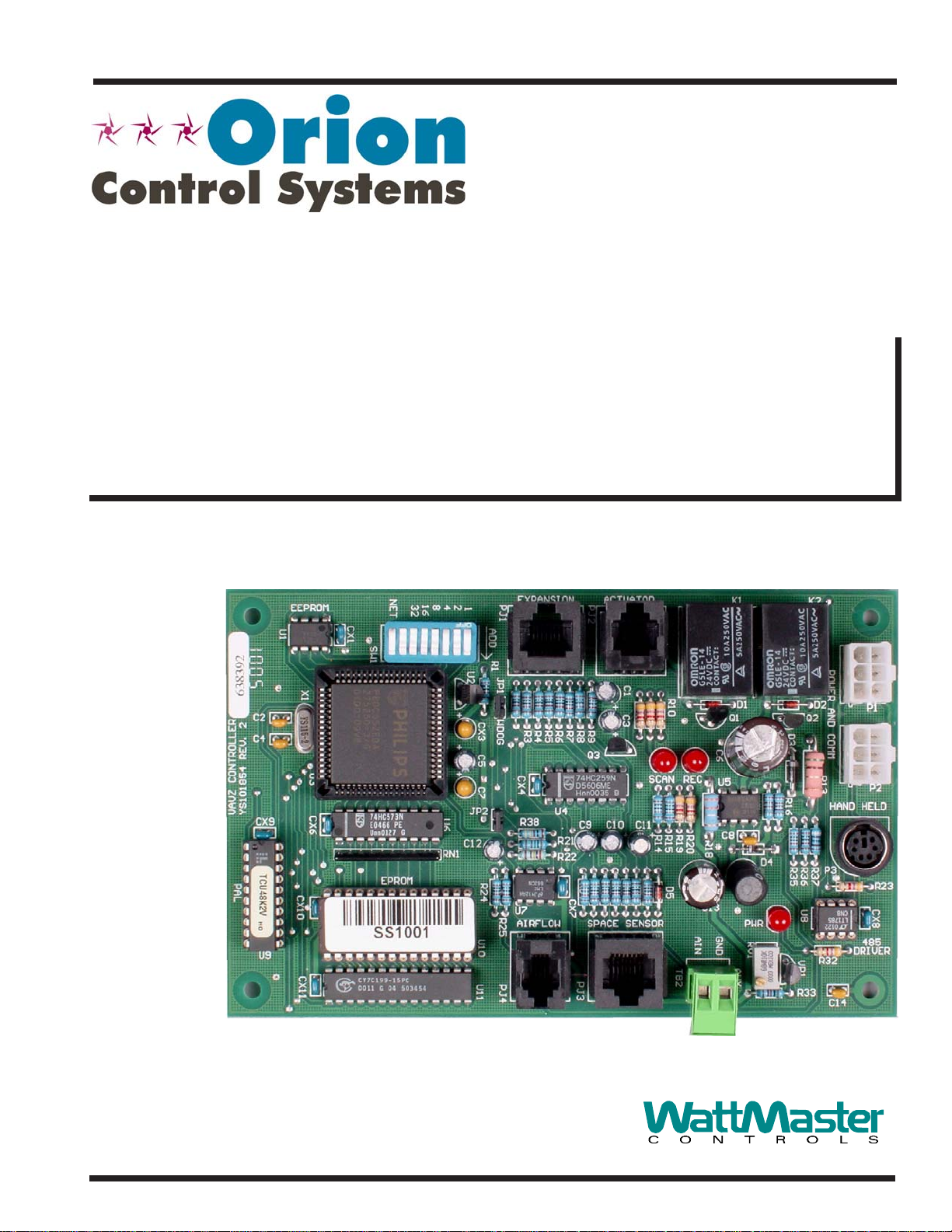
VAV/Zone Controller
This manual applies to the VAV/Zone controller that is included in the
following Orion products:
OE742-XX-VAVZ VAV/Zone Package
Pressure Dependent
OE744-XX-VAVZ VAV/Zone Package
Pressure Independent
OE520-XX VAV/Zone Round Damper
Assembly - Pressure Dependent
OE521-XX VAV/Zone Round Damper
Assembly - Pressure Independent
OE736-XX VAV/Zone Rectangular Damper Kit
The VAV/Zone Controller is used for controlling airflow and operation
of VAV or Zoning terminal units. It is a programmable digital controller
which allows for program setpoints to be stored in non-volatile memory.
The controller is connected to a room sensor via a modular cable assembly which monitors space temperature allowing the VAV/Zone controller to modulate a damper in response to space temperature, duct
temperature and airflow requirements in the controlled space.
The VAV/Zone controller has four integral modular jacks for connection to the actuator, airflow sensor (for pressure independent applications), room sensor and relay or analog expansion boards, via modular
cables. Molex cable connections are provided for the 24 VDC power
and system communications. A quick connect terminal connector is also
supplied for connection of the Modular Service Tool to facilitate pro-
gramming of the controller. The controller has an on-board dip switch
provided for board addressing.
The VAV/Zone controller is provided with two relays for tri-state control of the damper actuator. All outputs and the relay common are electrically isolated from all other circuitry on the board. All relay outputs
are supplied with transient suppression devices across each set of contacts to reduce EMI and arcing. The relay output contacts are rated for
pilot duty control of a maximum of 2 Amps @ 24 VAC or 24 VDC.
The actuator connects via a modular cable to the board and provides the
VAV/Zone controller with feedback monitoring for precise positioning
of the actuator.
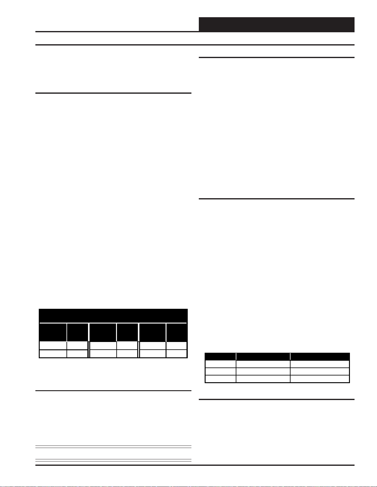
OE322 Output Expansion Boards
The OE322, 3 Relay with Analog Output Expansion board is used in
conjunction with the VAV/Zone Controller board to allow for control
of VAV and Zone terminal units, including series and parallel fan
terminal units with up to 3 stages of electric heat or modulating hot
water heat. The OE322, 3 Relay with Analog Output Expansion board
provides 3 relay outputs for pilot duty switching control, and 1 Analog
output for control of a 0-10 V modulating hot water valve.
The OE322 Output Expansion board connects to the VAV/Zone
controller board by means of a modular cable provided with the
expansion board. Power is supplied to the board by means of this
modular cable. Screw terminals are provided for connection of field
wiring to the relay and analog outputs.
The relay outputs are N.O. contacts with one common terminal. All
outputs and the relay common are electrically isolated from all other
circuitry on the board. All relay outputs are supplied with transient
suppression devices across each set of contacts to reduce EMI and
arcing. The relay output contacts are rated for pilot duty control of a
maximum of 2 Amps @ 24 V AC or 24 VDC. The analog output provides
a 0 – 10 VDC modulating signal output into a 1K ohm minimum load.
6.30”
U4
R21
R22
CX7
ACTUATOR
PJ2
C1
C3
R9R8R7R6R5
Q3
C9 C10 C11
PJ3
SCAN
K1 K2
IN
R10
R14
R15
D5
D1
Q1
C6
U5
REC
C8
R19
R20
R18
L1
C13
PWR
GND
AIN
RV1
AUX
TB2
D2
P1
Q2
D3
OUT
R33
R36
VR1
R37
R23
U8
HAND HELD
P3
R32
C14
P2
CX8
R16
D4
R35
4.00"
EEPROM
U1
C2
C4
VAVZ CONTROLLER
YS101854 REV.2
CX9
PAL
CX10
U9
CX11
4
U6
RN1
PJ1
1
ADD
R1
U2
JP1
CX3
R3
R4
WDOG
C5
CX4
C7
JP2
R38
C12
U7
R24
R25
U10
AIRFLOW SPACE SENSOR
U11
PJ4
NET
8
32162
CX1
SW1
X1
U3
CX6
EPROM
EXPANSION
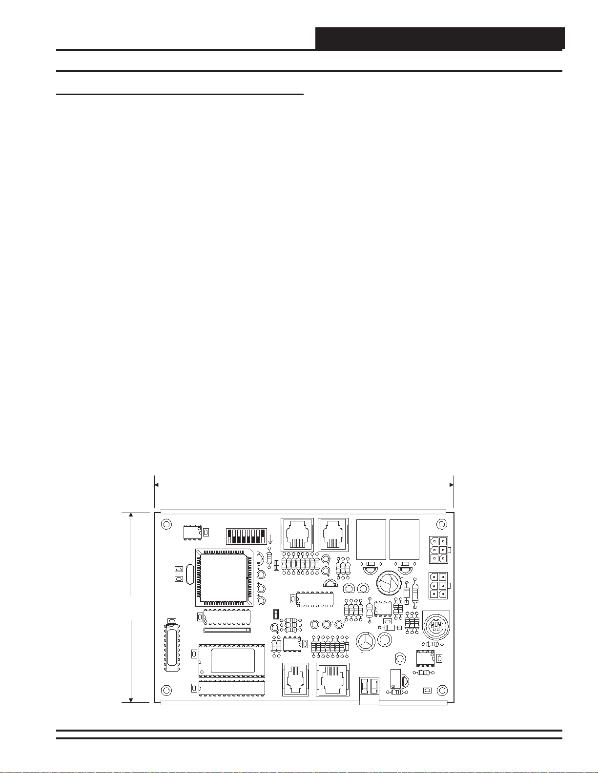
Figure 1: V AV/Zone Controller Dimensions
V AV/Zone Controller 3
Page 4
Technical Guide
Controller Over view
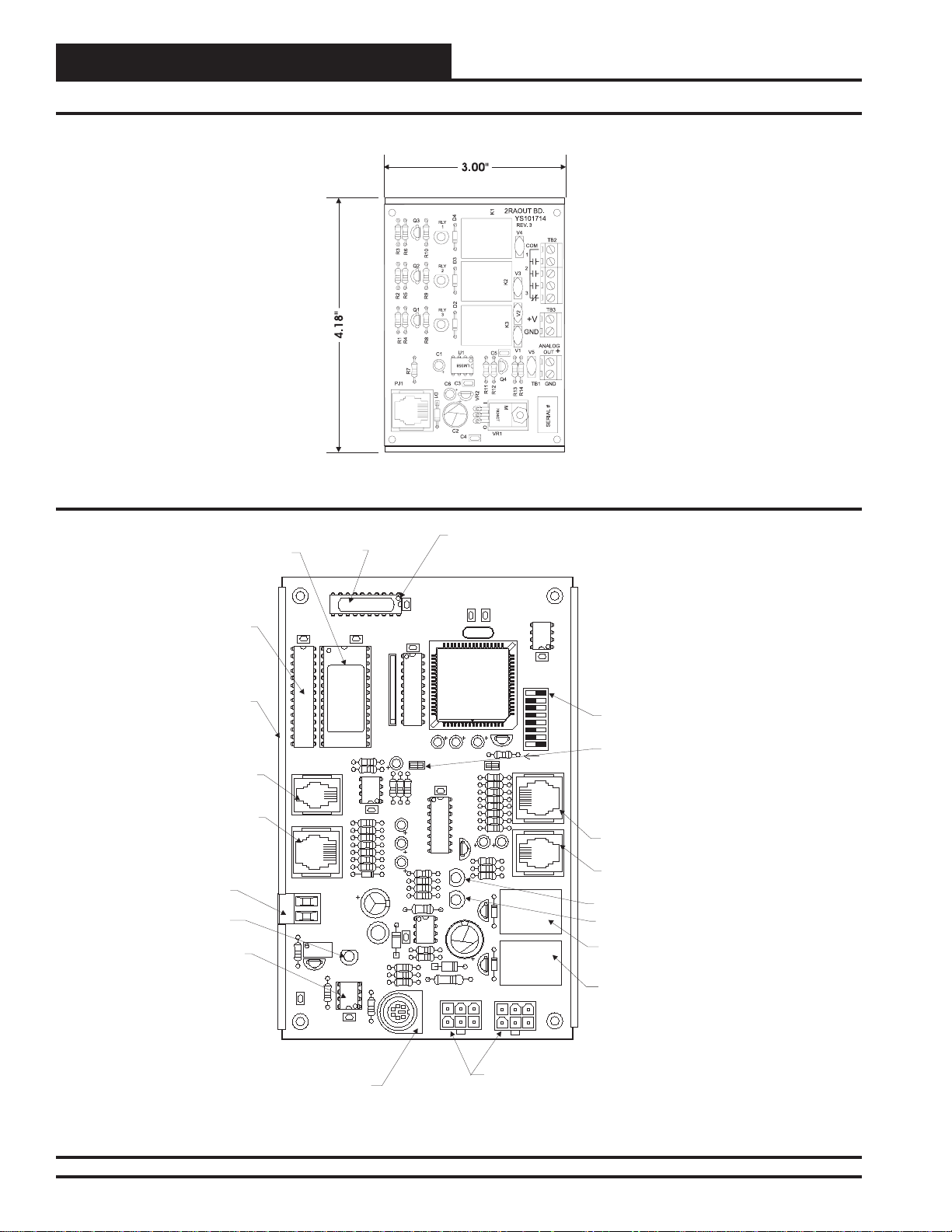
Figure 2: OE322 Output Expansion Boards
RAM
Chip
Snap Track
For Controller
Mounting
Air Flow Sensor
Modular Connector
Space Temp Sensor
Modular Connector
AUX- Supply Air
Sensor Wiring
Terminals
(When Used)
Power LED
Communications
Driver Chip
EPROM
Chip
C14
PAL
Chip
U9
CX11
U11
PJ4
PJ3
TB2
AUX
R33
VR1
R32
PAL
CX10
EPROM
RN1
U10
R24
R25
U7
AIRFLOW
SPACE SENSOR
AIN
GND
PWR
RV1
C12
R22
R21
CX7
R14
D5
R15
R19
C13
U8
CX8
R20
R18
L1
D4
R35
R36
R23
R37
P3
Typical
Pin 1
Indicator
VAVZ CONTROLLER
YS101854 REV. 2
CX9
U3
CX6
U6
JP2
C7
CX4
R38
U4
C9 C10 C11
SCAN
REC
U5
C8
R16
HAND HELD
P2
C2
C4
CX3
C5
WDOG
R3
R4
R5
R6
R7
R8
R9
Q3
C3
R10
C6
Q1
D1
D3
Q2
D2
OUT
P1
U1
X1
C1
EEPROM
CX1
SW1
NET
32
16
8
4
2
1
U2
ADD
R1
JP1
Address Switch
(Set Between1&58)
Jumper For Pressure
Independent Airflow
PJ1
Operation. Must Be On
EXPANSION
For High Velocity
Terminal Configurations
And Removed For Low
Velocity Applications
PJ2
ACTUATOR
Expansion Board
Modular Connector
Damper Actuator
Modular Connector
“SCAN” LED
“REC” LED
K1
Damper Actuator
Positioning Relay
“Open”
K2
IN
Damper Actuator
Positioning Relay
“Close”
Mini DIN Connector
Connect Modular Service
Tool Here For Programming
Figure 3: V AV/Zone Controller Component Locations
4
Modular Cable Connectors
Connects To Modular Cable From
Power/Com Board And Connects
To Next Controller On Loop
Supplies 24 VAC Power and RS-485
Communications In And Out Of Controller
V AV/Zone Controller
Page 5
Controller Inputs and Outputs
T ec hnical Guide
The following inputs and outputs are available on the VAV/Zone controller and the OE322 Output Expansion Board that can be added by
connecting it to the main controller board expansion port. For component locations of the inputs on the VAV/Zone Controller see Figure 3.
For wiring of inputs and outputs see Figure 4 thru 9.
V AV/Zone Controller Analog Inputs
Input #1: Space Temperature
The Modular Room Sensor that reads space temperature is attached to
this input. The Modular Sensor connects via a modular cable to the
VAV/Zone controller. If the optional push-button override sensor is installed, this input will detect user overrides from unoccupied back to
occupied operation for a user adjustable amount of time.
Input #2: Airflow Sensor
If the VAV/Zone Controller is to be configured for pressure independent operation, you need to install the OE274 Airflow Sensor and connect the modular plug from the pressure sensor to this input. The pressure signal from the Airflow Sensor is used for CFM (airflow) calculations. If an OE274 Airflow Sensor is attached to this input, the VAV/
Zone controller will automatically detect this and switch to pressure
independent operation. If the sensor is not attached or becomes defective, the controller automatically reverts to pressure dependent operation. When the VAV/Zone controller is used for pressure independent
applications, the JP2 jumper must be “ON” for high velocity systems
and “OFF” for low velocity systems. Typically VAV systems are medium to high velocity and voting systems are low velocity . As a rule of
thumb, if the velocity through the terminal unit is below 1500 FPM,
remove the jumper and if above 1500 FPM, leave the jumper on. If it is
a low velocity system, in addition to removing the jumper, the configuration option: “Is This a Voting System” must be YES, even on a VAV
system. If the CFM is greater than the values listed for the terminal inlet
size above, the JP2 jumper on the VAV/Zone controller must be installed and the system must be configured as a “Non-Voting System. If
this is a high velocity voting system the box must be configured as a”
voting box” but the system must be configured as “non-voting system”
in order for the airflow sensor to read correctly . See Figure 3 for jumper
location on board. See Table 1 for low velocity inlet CFM informa-
tion.
Maximum Inlet CFM for Low Velocity (1500 FPM)
Inlet
Size
6” Dia. 260 8” Dia. 500 10” Dia. 775
12” Dia . 1100 14” D ia. 1550 16” Dia. 2025
Notes:
1.) These va lues are averages and will vary between terminal unit
manuf actu rers.
Table 1: Maximum Inlet CFM for Low Velocity
Input #3: Aux - Supply Air Temperature Sensor
A Supply Air Temperature Sensor can be connected to these terminals.
It should be mounted in the supply duct close to the terminal unit where
the VAV/Zone controller is installed. This sensor can be used for monitoring purposes or in place of the Supply Air Temperature Broadcast
from the VCM Controller.
Note: All temperature sensors must be Thermistor Type III.
JP2 Jumper Removed
Box
CFM
Inlet
Size
Box
CFM
Inlet
Size
Box
CFM
Other Controller Connections
Expansion Board Modular Connector
This modular connector is used to connect the optional OE322 Output
Expansion Board to the VAV/Zone controller. These boards are only
required when electric or hot water heating and/or fan terminal control
is required. The expansion boards are not required for cooling only
terminal units.
Actuator Modular Connector
This modular connector is used to connect a modular cable from the
VAV/Zone controller to a tri-state actuator.
Power/Comm Modular Connectors
These two modular connectors, (labeled P1 & P2) are used to connect
modular cables from the Power/Comm board that supplies 24 V olt power
and communications to the controller and to supply 24 Volt power and
communications to the next controller on the local loop.
Modular Service Tool DIN Connector
This connector is used to connect a cable between the Modular Service
T ool and the VA V/Zone controller for programing and configuration of
the VAV/Zone controller.
Optional - OE322 Expansion Board
As previously stated when control of a fan or if heating is required the
OE322 Output Expansion board must be used.
Relay Output #1 - Fan Enable
The first expansion relay on the Output Expansion boards is used for
enabling the fan for Series or Parallel Fan Terminal Units.
Relay Output #2 - Stage 1 Heating
If you have at least one stage of auxiliary heating, this is the relay used
to energize the 1st stage of terminal unit heating. This heating stage can
either be used with electric heat or On/Off hot water valve control.
Relay Output #3 - Stage 2 Heating
If you have two stages of auxiliary heating, this relay controls the 2nd
stage of electric heat. For 3 stage heating, this relay output would be
energized for both the 2nd and 3rd stage of heat. See the following
section for more information regarding 3 stage heating applications.
3 Stage Heating Applications
If three stages of electric heat are configured, relays #2 and #3 will
stage in a staggered sequence. This allows you to achieve 3 stages of
heating using only relays #2 and #3. Each of the 3 heating elements
should be sized for 1/3 of the total KW output required. Both the 2nd
and 3rd stage heating contactors (C2 & C3) must be connected to Relay
Output #3. See Table 2 for relay sequencing information.
Stage No. Relay Output #2 Relay Output #3
#1 ON (C1) OFF (C2 & C3)
#2 OFF (C1) ON (C2 & C3)
#3 ON (C1) ON (C2 & C3)
Table 2: Relay Sequencing For 3 Stage Heating
24 VDC Power Terminals (+V & GND)
These terminals can supply 24 Volts DC for a 24 VDC hot water valve
actuator if desired. This output is rated at 12 Watts maximum load.
Analog Output
If you are using hot water or steam heating via a modulating steam or
hot water valve, this output can supply a 0-10 Volts DC signal for proportional control of the valve.
V AV/Zone Controller
5
Page 6
Technical Guide
Hi
Lo
Controller Inputs and Outputs
Airflow Probe & Sensor
(For Pressure Independent Applications Only)
Airflow
Room Sensor
W
A
R
M
E
R
NORMAL
C
O
O
OVR
L
E
R
Supply Air
Temperature
Sensor
(See Note 3)
Locate In Supply Duct
Near Zone Damper
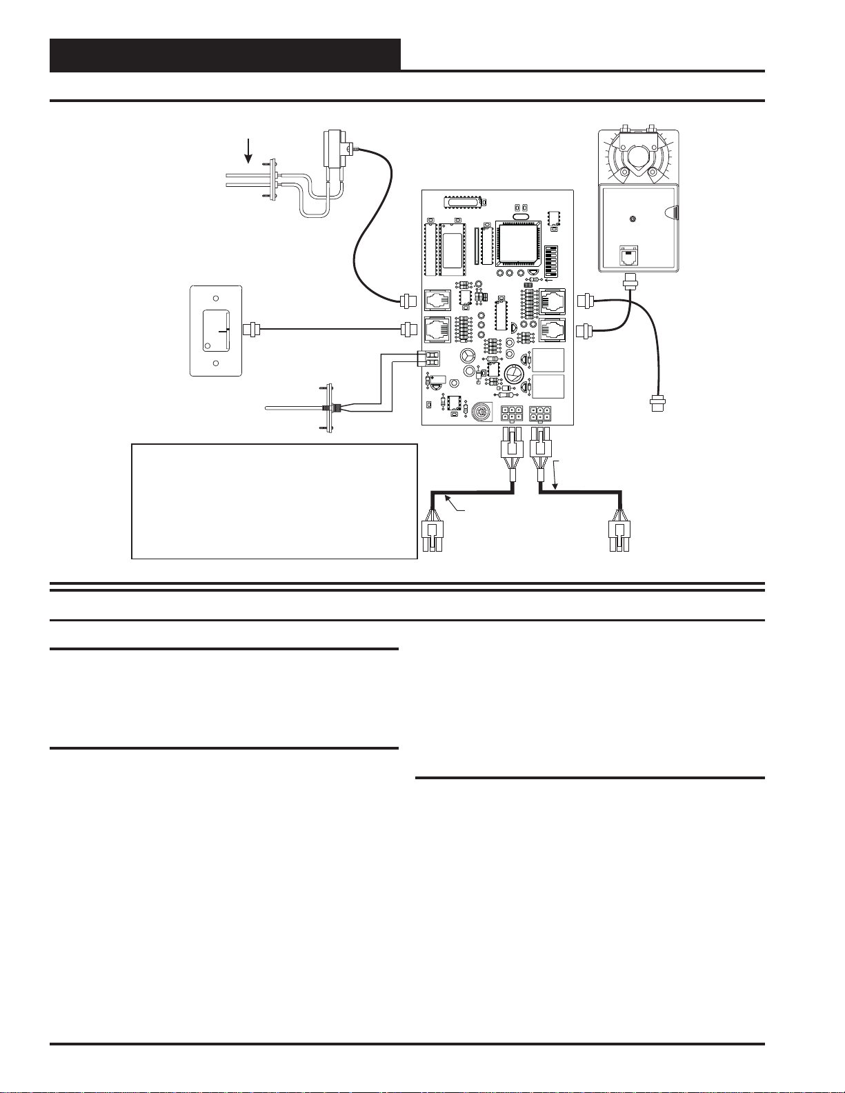
Notes:
1.) All wiring to be in accordance with local and national electrical codes
and specifications.
2.) Use Orion prefabricated modular cables for connection between the
VAV/Zone controller, the Power/Comm Board and between each VAV/Zone
controller on the loop.
3.)The Supply Air Sensor is not required when the VAV/Zone Controller is
connected to an Orion VAV/CAV Unit Controller board. A global supply air
temperature is broadcast by the VAV/CAV Unit Controller. The Supply Air
Sensor is only required if the VAV/Zone Controller is required to operate as a
“Stand Alone” controller. It can also be used on VAV/Zone controllers that have
reheat to monitor the box discharge air temperature.
VAV/Zone Controller Board
U9
R25
PJ4
AIRFLOW
PJ3
SPACESENSOR
TB2
AIN
GND
P2
P1
Power/Comm Cable To
Next VAV/Zone Controller or
Power/Comm Distribution Board
Zone Actuator
10
SW1
NET
32
16
8
4
2
1
ADD
PJ1
EXPANSION
PJ2
ACTUATOR
To Optional Relay
Expansion Board
Power/Comm Cable
From Power/Comm Distribution Board
Or Previous VAV/Zone Controller
Figure 4: V AV/Zone Controller Wiring
Controller Installation & Wiring
General
Correct wiring of the VAV/Zone controller is the most important factor
in the overall success of the controller installation process. The VAV/
Zone controller wiring has been simplified by the use of modular connectors and prefabricated modular cables.
Controller Mounting
If the Round Zone Dampers or Rectangular Zone Damper Kits were
purchased from WattMaster, the controller and actuator are factory
mounted and wired in the damper control enclosure. If your VAV/Zone
controllers are pressure independent, an airflow probe and pressure sensor will also be factory mounted and wired.
Most terminal unit manufacturers will offer the option of factory mounting the Orion controls in their terminal units for an additional charge.
An installation worksheet and instructions are available for the Orion
V AV/Zone controller package which can be shipped with the V AV/Zone
control(s) to the terminal unit manufacturer to simplify third party factory mounting and wiring of the controller.
When the VAV/Zone controller is to be field mounted, it is important to
mount the controller in a location that is free from extreme high or low
temperatures, moisture, dust and dirt. The VAV/Zone controller board
must be mounted within 10” of the damper actuator in order for the
actuator cable to extend between the controller and the actuator.
Be careful not to damage the electronic components when mounting
the controller. Remove the controller from its snap track mount. Mark
the control enclosure base using the snap track as a template. Drill pilot
holes in the enclosure base and secure the snap track to it using sheet
metal screws. Do not allow metal shavings to fall onto the circuit board.
Reattach the controller to the snap track. Mount the damper actuator to
the damper shaft following the instructions supplied with the damper
actuator.
Important Wiring Considerations
Please carefully read and apply the following information when wiring
the VAV/CA V controller. See Figur e 4 for VA V/Zone controller wiring
diagram.
1. Size and wire the Power/Comm Board transformer per the
instructions. Failure to size the transformer and/or wire the
Power/Comm board correctly may cause the VAV/Zone
controllers to operate erratically or not at all. See
Figure 5 for wiring and transformer sizing information.
2. If a Supply Air Sensor is to be connected, the minimum
wire size used should be 24 gauge.
3. Do not pry on the connectors when connecting or
disconnecting the modular cables. Be sure to push in on the
connector release clip and then pull straight up.
6
V AV/Zone Controller
Page 7
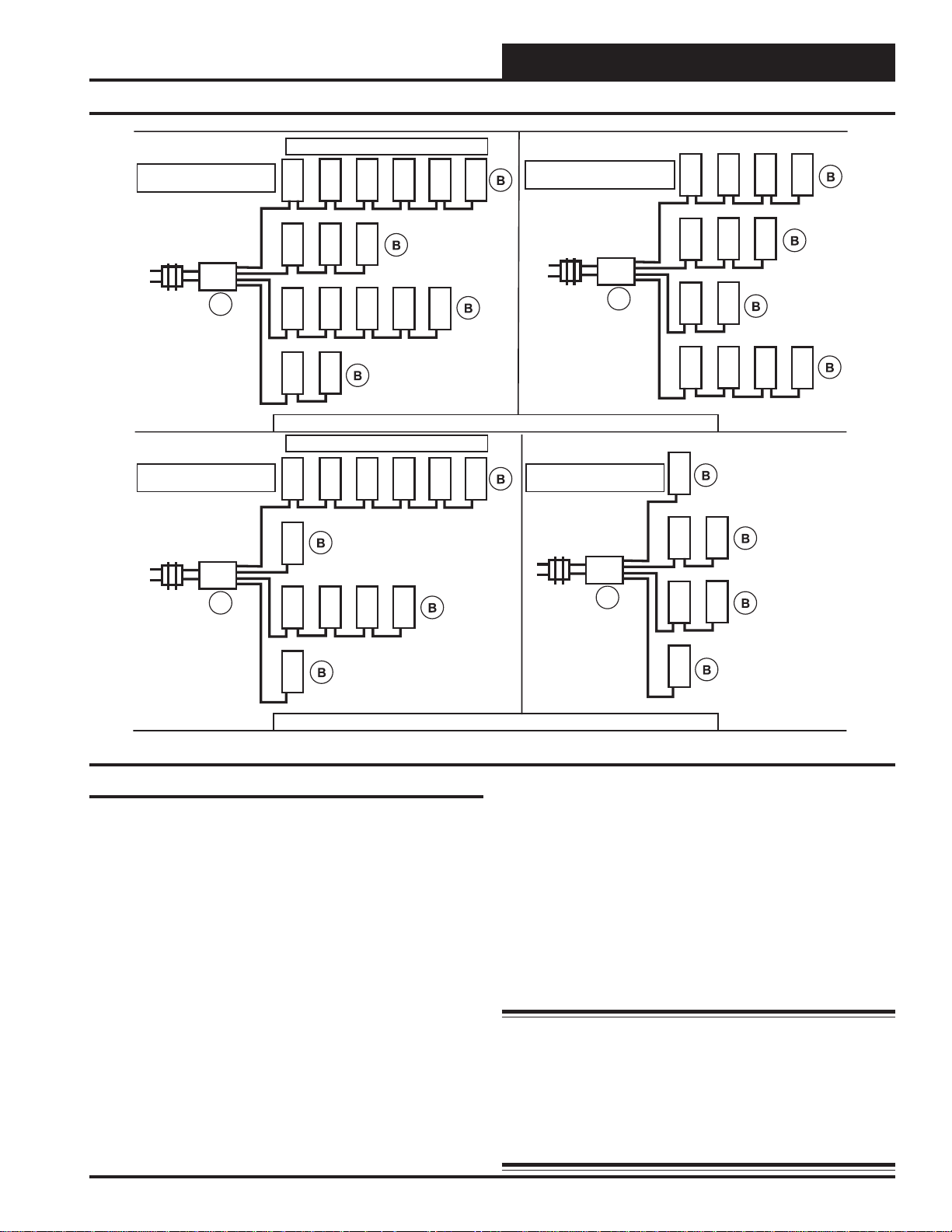
16 Devices At 6 VA = 96 VA
Use 100 VA Transformer
6 Devices Maximum Per Branch Circuit
T ec hnical Guide
13 Devices At 6 VA = 78 VA
Use 80 VA Transformer
Power/Comm
Board
120 / 24VAC
100 VA
Transformer
Minimum
See Warning
Note Below
12 Devices At 6 VA = 72 VA
Use 75 VA Transformer
120 / 24VAC
75 VA
Transformer
Minimum
See Warning
Note Below
A
Power/Comm
Board
A
Power/Comm
Board
120 / 24VAC
80 VA
Transformer
Minimum
See Warning
Note Below
Total length of all modular cables used on each branch ( A to B) cannot exceed 240 Ft.
6 Devices Maximum Per Branch Circuit
6 Devices At 6 VA = 36 VA
Use 40 VA Transformer
120 / 24VAC
40 VA
Transformer
Minimum
See Warning
Note Below
A
Power/Comm
Board
A
Total length of all modular cables used on each branch ( A to B) cannot exceed 240 Ft.
Figure 5: V AV/CAV Controller Transformer Sizing
Modular Devices - Transformer Sizing
Modular devices include the VAV/Zone Controller, Modular System
Manager & MiniLink Polling Device. All of these devices connect to
each other and a Power/Comm Board using prefabricated modular cables.
When sizing transformers for these devices it is important to design
your layout so that the fewest number of Power/Comm distribution
boards and the least number of transformers can be used.
In order to simplify wiring design and layout with modular devices the
following rules apply:
1. Power/Comm Board maximum transformer size = 100 VA.
This is due to the board circuitry and fusing. Each modular
device is to be calculated at 6 VA. This allows for a
maximum of 16 devices per Power/Comm board. If more
than 16 devices are required, multiple Power/Comm boards
must be used. Any Slaved Zone actuators used are
considered a modular device and must be accounted for at
6 VA. each. They also must be included in the branch
circuit maximum quantity of 6. See rule #2 below.
2. No more than 6 modular devices allowed per branch circuit.
(Each Power/Comm board has 4 branch circuits
available on the board )
3. The longest total run per branch circuit is 240 Ft. This is
due to voltage drop on the prefabricated cable. If cable runs
longer than 240 Ft. are required, additional Power/Comm
board(s) can be used. Each Power/Comm Board connected
in series with the first Power/Comm Board would allow for
an additional 240 Ft. of modular cable to be added to the
total cable run length.
See Figure 5 for information and some examples of transformer sizing
and branch circuit design.
Warning: Do not ground the 24 V transformer that is to be
used with the Power/Comm boards. Grounding
of the transformer will damage the Power/Comm
board and all boards connected to it. A separate
transformer must be used for each Power/Comm
board. No exceptions. Do not connect any other
devices to the transformer used for the Power/Comm
board.
V AV/Zone Controller
7
Page 8
Technical Guide
Controller Installation & Wiring
HZ000095
EXPANSION
ACTUATOR
PJ2PJ1
(OE324) ZONE CONTROLLER BOARD
OE520, OE736, OE742
SLAVED- ZONE ACTUATOR #2
(WHEN USED)
OE523, OE738, OE282-03
ZONE ACTUATOR #1
(MASTER)
10
OE282
HZ000095
MODULAR CABLE
SLAVED-ZONE ACTUATOR #1
1 10 0
OE523, OE738, OE282-03
MODULAR CABLE
(PL101824) BYPASS AND
OE267
SLAVE INTERFACE CARD
CLOSE
OPEN
TB1
GND
FDBK
CLOSE
OPEN
GND
PJ2
FROM ZONE
CONTROLLER
TB2
PJ1
TOACTUATOR
LD2
OPEN
SLAVEINTERFACE
YS101824
LD1
CLOSE
BYPASSAND
OE282 OE282
MODULAR
CABLE
(PL101824) BYPASS AND
SLAVE INTERFACE CARD
TOACTUATOR
BYPASSAND
SLAVEINTERFACE
YS101824
PJ1
GND
OPEN
TB2
CLOSE
OPEN
CLOSE
FROM ZONE
CONTROLLER
PJ2
LD2
LD1
FDBK
GND
TB1
OPEN
CLOSE
HZ000095
NOT USED FOR
THIS APPLICATION
(PL101824) BYPASS AND
SLAVE INTERFACE CARD
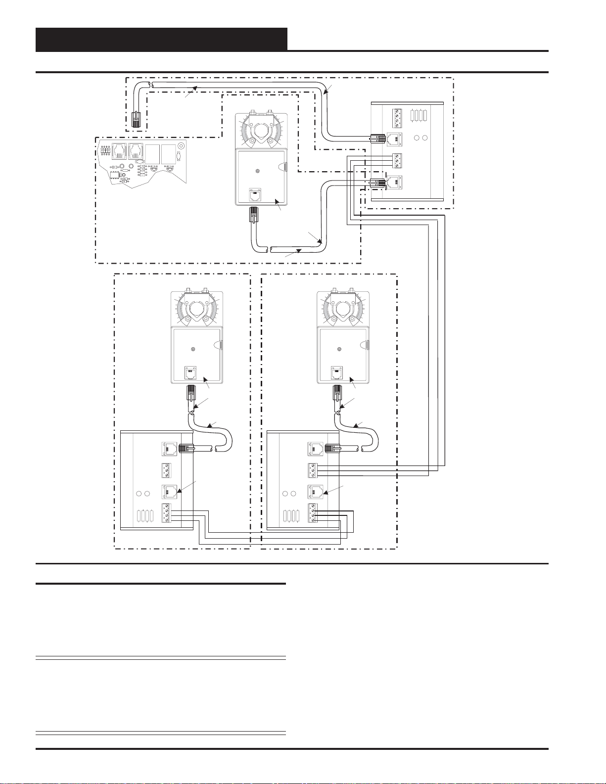
Figure 6: Slaved Zone Wiring & Connection Diagram
Slaved Zone Damper Wiring
For large zones it may be necessary to have more than one air damper
controlled by a VAV/Zone controller and its associated space sensor.
The Orion system allows for connecting up to two additional slaved
zone dampers to the master VAV/Zone controller. Slaving is not avail-
able for pressure independent damper applications.
Note: Each slaved actuator is considered a modular device rated
at 6 VA each. This 6 VA load must be included in the
transformer sizing and branch circuit calculations for the
Power/Comm board. See the previous section regarding
transformer sizing of the Power/Comm board for complete information.
MODULAR
CABLE
HZ000095
TOACTUATOR
BYPASSAND
SLAVEINTERFACE
YS101824
PJ1
GND
OPEN
TB2
CLOSE
FDBK
GND
OPEN
CLOSE
NOT USED FOR
THIS APPLICATION
CLOSE
LD1
OPEN
FROM ZONE
CONTROLLER
PJ2
LD2
TB1
T wo Slave W iring Adapters (OE267) consisting of a slave wiring interface card and modular cable are supplied with the OE523 Round Slaved
Zone Damper, OE738 Slaved VAV/Zone Rectangular Damper Kit and
the OE282-03 Slaved VAV/Zone Damper Kit. These are required when
attaching slave actuator(s) to the master zone damper. One slave wiring
interface card should be mounted in the control enclosure of the master
VAV/Zone controller. It is mounted by fastening the plastic snap-track
to the control enclosure with sheet metal screws provided. The other
card is mounted in the control enclosure of the slaved zone damper.
Fasten it in the control enclosure of the slaved zone damper as was
previously done with the master VAV/Zone controller. Run 24 AWG
minimum wire between the slave wiring interface cards. Connect modular cables to the slave wiring interface cards and to the zone actuators
as shown. See Figure 6 for complete wiring details.
8
V AV/Zone Controller
Page 9
Expansion Board Installation & Wiring
T ec hnical Guide
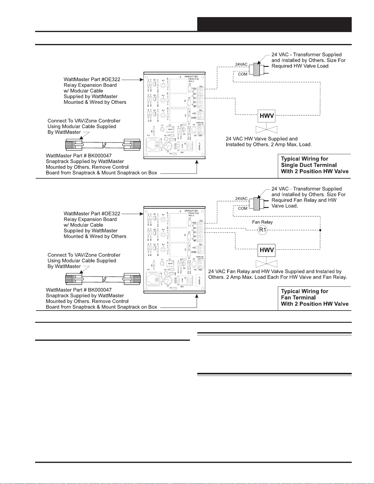
Figure 7: Expansion Board Wiring For Two Position Hot Water Heat Applications
Wiring Considerations
Warning: The 3 relay outputs available on the OE322
Expansion boards are used to supply extra relays and/or analog outputs
to control fan and heating functions for the VAV/Zone controller.
When Round VAV/Zone Dampers or Rectangular VAV/Zone Controller Kits are ordered from WattMaster, the OE322 Expansion board is
shipped loose for field mounting by others.
Mounting of the OE322 Expansion Board is identical to the previously
described mounting for the VAV/Zone controller. Mount the Expansion
board near the VAV/Zone controller using the sheet metal screws provided. Be sure the mounting location is close enough so that the supplied modular cable will reach from the VAV/Zone controller to the
Expansion board.
The wiring consideration information previously outlined for the VAV /
Zone controller should be followed when wiring the OE322 Expansion
Boards.
Output Expansion board are each rated for 2 Amps
@ 24 VAC. If your device load exceeds these limits,
a pilot duty relay (by others) must be used in the
circuit.
V AV/Zone Controller
9
Page 10

Technical Guide
Expansion Board Installation & Wiring
WattMaster Part #OE322
Relay Expansion Board
R3
w/ Modular Cable
R6
Supplied by WattMaster
Mounted by Others
Connect To VAV/Zone Controller
Using Modular Cable Supplied
By WattMaster
PJ1
WattMaster Part # BK000047
Snaptrack Supplied by WattMaster
Mounted by Others. Remove Control
Board from Snaptrack & Mount Snaptrack on Box
24VAC
2RAOUT BD.
K1
D4
Q3
RLY
1
R10
D3
RLY
Q2
2
R9R5R2
D2
Q1
RLY
3
R8R4R1
U1
C1
R7
C3
C6
D1
C2
C4
YS101714
REV.3
V4
TB2
COM
1
2
V3
K2
3
TB3
V2
+V
K3
GND
ANALOG
V1
OUTV5
C5
LM358
Q4
R11
R12
VR2
I
7824CT
O
VR1
+
Note: 3 Stage Heating is Attained by Sizing All 3
TB1 GND
R14
R13
M
Heating Elements For Equal KW Output. Each
Element Should be Sized for 1/3 of the Total KW
Output Required. To Achieve 3 Stage Heating the
System would be Configured to Energize
SERIAL #
Contactor C1 for First Stage Heat. For 2nd Stage
Heat the System Would be Configured to Deenergize Contactor C1 and Energize Contactor C2
& C3. For 3rd Stage Heat the System Would be
Configured to Leave Contactor C2 & C3 Energized
and also Energize Contactor C1.
COM
C1
C2
C3
& Wired by Others. Size For
Required Contactor(s) Load.
1st Stage Heat Contactor
2nd Stage Heat Contactor
3rd Stage Heat Contactor
24 VAC Contactor(s)
Supplied & Installed
By Others. 2 Amp
Max. Load Each.
Typical Wiring for
Single Duct Terminal
with Electric Heat
24 VAC Transformer Supplied
24VAC
2RAOUT BD.
K1
D4
Q3
RLY
1
R10
D3
RLY
Q2
2
R9R5R2
D2
Q1
RLY
3
R8R4R1
U1
C1
R7
C3
C6
D1
C2
C4
YS101714
REV.3
V4
TB2
COM
1
2
V3
K2
3
TB3
V2
+V
K3
GND
ANALOG
V1
OUTV5
C5
LM358
Q4
R11
R12
VR2
I
7824CT
O
VR1
+
TB1 GND
R14
R13
M
SERIAL #
COM
Fan Relay
24 VAC Fan Relay
Supplied & Installed
By Others. 2 Amp
Max. Load.
24 VAC Transformer Supplied
& Wired by Others. Size For
Required Fan Relay Load.
R1
Typical Wiring for
Fan Terminal Unit
with Cooling Only
2RAOUT BD.
K1
WattMaster Part #OE322
Relay Expansion Board
w/ Modular Cable
Supplied by WattMaster
Mounted & Wired by Others
Connect To VAV/Zone Controller
Using Modular Cable Supplied
By WattMaster
WattMaster Part # BK000047
Snaptrack Supplied by WattMaster
D4
Q3
RLY
1
R3
R6
R10
D3
RLY
Q2
2
R9R5R2
D2
Q1
RLY
3
R8R4R1
U1
C1
R7
PJ1
C3
C6
D1
C2
C4
YS101714
REV.3
V4
TB2
COM
1
2
V3
K2
3
TB3
V2
+V
K3
GND
ANALOG
V1
OUTV5
C5
LM358
Q4
R11
R12
VR2
I
7824CT
O
VR1
+
Note: 3 Stage Heating is Attained by Sizing All 3 Heating
Elements For Equal KW Output. Each Element Should be
TB1 GND
Sized for 1/3 of the Total KW Output Required. To Achieve 3
R14
R13
M
Stage Heating the System would be Configured to Energize
Contactor C1 for First Stage Heat. For 2nd Stage Heat the
System Would be Configured to De-energize Contactor C1
SERIAL #
and Energize Contactor C2 & C3. For 3rd Stage Heat the
System Would be Configured to Leave Contactor C2 & C3
Energized and also Energize Contactor C1.
Mounted by Others. Remove Control
Board from Snaptrack & Mount Snaptrack on Box
Figure 8: Expansion Board Wiring For Electric Heat Applications
10
24VAC
COM
Fan Relay
C1
C2
C3
24 VAC Transformer Supplied &
Wired by Others. Size For Required
Fan Relay & Contactor(s) Load.
R1
1st Stage Heat Contactor
2nd Stage Heat Contactor
3rd Stage Heat Contactor
Typical Wiring for
Fan Terminal Unit
with Electric Heat
V AV/Zone Controller
24 VAC Fan
Relay &
Contactor(s)
Supplied &
Installed By
Others. 2
Amp Max.
Load Each.
Page 11

T ec hnical Guide
Figure 9: Expansion Board Wiring For Modulating Hot Water Heat Applications
Star t-up & Commissioning
General
In order to have a trouble free start-up it is important to follow a few
simple procedures. Before applying power for the first time it is very
important to correctly address the controller and run through a few simple
checks.
Controller Addressing
All VAV/Zone controllers are equipped with address switches. If the
VAV/Zone controller is to operate as a Stand Alone controller (not connected to any other HVAC unit or VA V/Zone controllers) the controller
address switch should be set for address 1. When the VAV/Zone controller is to be connected to other controllers on a communication loop,
each VAV/Zone controllers address switch must be set with a unique
address between 1 and 58.
V AV/Zone Controller
When programming the VAV/Zone controller on a Stand Alone or Interconnected System and you are asked to enter the Unit ID, you would
enter the address for the controller you wish to program. When programming the VAV/Zone controller on a Networked System and you
are asked to enter the Unit ID, you would first enter the MiniLink loop
address for the loop the controller is connected to and then enter the
VAV/Zone controllers address. See Figure 10 for a diagram depicting
address switch settings.
For detailed information regarding communication wiring and connection for Interconnected and Networked systems, please see the Orion
System Installation & Troubleshooting Guide.
11
Page 12

Technical Guide
Star t-up & Commissioning
Address Switch Shown Is
Set For Address 9
ADD
1
2
4
8
16
32
NET
SW1
ADD
Controller
Address Switch
The Address For Each Controller
Must Be Between 1 And 58 And Be
Unique To The Other Controllers
On The Local Loop
ADD
Address Switch Shown Is
Set For Address 13
VAV/Zone Controller Board
P1
R
TO
A
TU
AC
PJ2
N
SIO
EXPAN
PJ1
ADD
1
2
4
8
16
32
NET
SW1
P2
R
SO
SEN
E
SPAC
W
FLO
AIR
R25
GND
AIN
TB2
PJ3
PJ4
U9
Figure 10: Address Switch Setting
Power Wiring
One of the most important checks to make before powering up the system for the first time, is to confirm proper voltage and transformer
sizing for the Power/Comm board that is connected to it. Each VAV/
Zone controller requires 6 VA of power delivered to it at 24 VAC. See
pages 7 and 8 of this manual for complete wiring and transformer sizing
information for the V AV/Zone controller and its associated Power/Comm
board. All VAV/Zone controllers must be connected to a Power/Comm
board using prefabricated modular cables.
Check all modular connectors to be sure they are completely pushed
and locked into their mating connectors. Confirm that all sensors required for your system are mounted in the appropriate location and that
the modular cables are plugged into the correct connectors on the VAV/
Zone controller. Check the actuator cable and be sure it is plugged in
and secured to the modular connector on the actuator and the VAV/
Zone controller board modular connector . Check that the Modular Room
Sensor modular connector is connected to one end of the modular sensor cable and the other end is connected to the modular sensor connector on the VAV/Zone controller board. Be sure any expansion boards
connected to the VAV/Zone controller are also correctly wired per the
expansion board wiring instructions on pages 7 through 12 of this manual.
After all the above wiring checks are complete, apply power to the
Power/Comm board that is connected to the VAV/CAV controller(s).
Initialization
Upon applying power to the VAV/Zone controller the following should
occur:
On system power-up, the SCAN LED is extinguished for a few seconds
and then the controller “flashes” its address switch setting. If the address switch were set to 7, you would see 7 flashes. After the address is
finished, the LED will extinguish for another 5 seconds. At the conclusion of this 5-second delay, the LED will begin a continuous flashing
while the Damper Feedback limits are calibrated. If the Damper is driving open, the LED will blink slowly. If the Damper is driving closed,
the LED will blink fast. When the calibration is completed, the normal
diagnostic flashes will commence. These diagnostic flashes are described
later in this document. In addition, during the first few seconds of powerup, all default setpoints are initialized and all outputs are turned off.
There is also a 30 second start-up delay to protect the fan and other
components from short cycling during intermittent power conditions. If
all inputs are operating correctly it will blink once every ten seconds.
12
V AV/Zone Controller
Page 13

T ec hnical Guide
Programming The Controller
The next step is programming the controller for your specific requirements. In order to configure and program the VAV/Zone controller you
must have a central operators interface or a personal computer with the
Prism computer front end software installed. Two different operators
interfaces are available for programming of the VAV/Zone controller.
You may use either the Modular Service Tool or the Modular System
Manager to access the status and setpoints of any VAV/Zone controller
or VAV/CAV controller on the system’s communications loop. See the
Modular Service Tool and System Manager Programming guide for
VAV/Zone controller programming information. If you are going to use
a personal computer and the Prism computer front end software, please
see the Orion Prism Computer Front End Operations Manual. No matter which operators interface you use, it is recommended that you proceed with the programming and setup of the controller in the order that
follows:
1. Configure The Controller For Your Application
2. Program The Controller Setpoints.
3. Review Controller Status Screens To Verify System
Operation And Correct Controller Configuration
Mode
Selection
STATUS
SETPOINTS
SCHEDULES
OVERRIDES
ALARMS
CONFIGURATION
BALANCE - TEST
ON
PREV
UP
DOWN
ESC
ENTER
13
2
5
4
708
DEC
Figure 11: Operators Interfaces
CLEAR
6
9
MINUS
-
NEXT
13
2
MINUS
-
PREV
6
9
4
708
DEC
5
System Manager
UP
NEXT
DOWN
ENTER
CLEAR
ESC
STATUS
SETPOINTS
SCHEDULES
OVERRIDES
ALARMS
V AV/Zone Controller
13
Page 14

Technical Guide
Sequence Of Operations
Initialization
On system power-up, the SCAN LED is extinguished for a few seconds
and then the controller “flashes” its address switch setting. If the address switch were set to 7, you would see 7 flashes. After the address is
finished, the LED will extinguish for another 5 seconds. At the conclusion of this 5 second delay, the LED will begin a continuous flashing
while the Damper Feedback limits are calibrated. If the Damper is driving open, the LED will blink slowly. If the Damper is driving closed,
the LED will blink fast. When the calibration is completed, the normal
diagnostic flashes will commence. These diagnostic flashes are described
later in this document.
V AV/Zone Configuration & Setup
There are a few configuration selections available to the user, which
can be used to tailor the software operation to match the mechanical
equipment this controller is installed on. These are programmed using
either the Modular System Manager, Modular Service Tool or a personal computer with Prism computer front end software installed. See
the Operator Interfaces Technical Guide or the Orion Prism Computer
Front End Software manual for specific programming information.
General
Several options are available to configure the VAV/Zone controller for
the appropriate equipment it is installed on. All of these options can be
set from the “Configuration” menu with the exception of “AHU Heat
Call” which is set from the “Setpoints” menu. Again, please refer to the
Operators Interface T echnical Guide or the Orion Prism Computer Front
End Software manual for detailed programming information.
Box Control Method
Set this configuration item for the type of box the VAV/Zone controller
is used on. The options available are:
0 = Cooling Only Box (With Reheat if Required)
1 = Heating/Cooling Changeover Box
2 = Series Fan Powered Box With Reheat
3 = Parallel Fan Powered Box With Reheat
Damper Operating Mode
This allows the user to set the direction of rotation the damper moves
when driving towards its full open position. The options available are:
0 = Direct Acting (Clockwise To Open Damper)
1 = Reverse Acting (Counterclockwise To Open Damper)
Voting System
If this system is a “Zoned” system as opposed to a true VAV system this
option must be set to “Yes”. If it is a true “VAV” system the option
should be set to “No”. The options available are:
0 = Yes
1 = No
Voting Zone
If this particular VAV/Zone controller is being used on a “Zoning”
system as opposed to a true VAV system, this option must be set to
allow the MiniLink Polling Device to determine if this controller should
be included in the zoning system voting process. If this is set to “Yes”
this controller will be included in the voting process. If this is a zoning
system and it is set to “No” this controller will not vote in the zoning
system voting process. If it is a true “VAV” system, the option should
be set to “No”. The options available are:
0 = Yes
1 = No
Pressure Independent Boxes - Airflow @ 1” W.C.
If this is a pressure independent box, this option allows you to calibrate
the box CFM correctly using the box manufacturers “K” factor. Enter
the correct “K” (CFM) factor for the inlet diameter of the box you are
configuring.
Expansion Relays - Steps of Reheat
If the box has reheat supplied by an electric coil, this option must be set
for the number of electric heating stages on the box. If the box has hot
water heat with a 2 position hot water valve, set the number of stages to
“1”. For hot water heat with a proportional hot water valve this must be
set for “0”. Options available are:
0 = No Staging
1 = 1 Stage of Reheat
2 = 2 Stages of Reheat
3 = 3 Stages of Reheat
Proportional Heating Signal
If the box has hot water reheat using a proportional hot water valve, set
this option to match the voltage signal required by the hot water valve
you are using. Options available are:
0 = 0-10 VDC Voltage Signal
1 = 2-10 VDC Voltage Signal
Allow Box Heat With AHU Heat
If the box you are using has reheat or auxiliary heat, configuring this
setting to 1=Yes will allow the box heat to operate at the same time as
the HVAC unit heat. Options available are:
0 = No
1 = Yes
Main Fan Status
If the VAV/Zone controller is installed on a non-fan powered box that
has reheat set this option to “Yes” in order to enable box reheat only
when the HVAC unit fan is running. A full description of how this
setting affects the various box types in the occupied and unoccupied
modes is contained under the “Mode Sequence” heading that follows
later in this manual. Options available are:
0 = No Heat can operate without fan
1 = Yes Heat cannot operate without fan
Push Button Override Group ID#
During Unoccupied Mode, all V AV/Zone controllers with a corresponding Group ID# will resume Occupied operation whenever any of the
VAV/Zone controllers with the same Group ID # has it’s push-button
depressed to initiate an override condition. This allows you to group
zones in various areas of the building. For example, individual tenants
with several offices could restore occupied mode for just their zones
and not affect other zones in the building. If you don’t want a specific
zone to be a part of any group, enter a ‘0’ for its Group ID #.
14
V AV/Zone Controller
Page 15

T ec hnical Guide
Dump Zone
If this VAV/Zone controller is to be used as a “Dump Zone” set this
configuration to 1=Yes. The dump zone is a controller without an actuator that is used to control a duct heater or auxiliary heat. Options
available are:
0 = No
1 = Yes
AHU Heat Call
This setting is located under the “Setpoints” menu on screen #3. This is
used only for the unoccupied mode. For non-fan powered terminal units
this temperature setpoint is used to allow auxiliary heat such as baseboard heaters to be energized in an attempt to satisfy the heating demand prior to initiating the HVAC unit Supply Air Heating mode. For
fan powered terminal units this setpoint can be used to operate the series or parallel box to satisfy the heating demand by using plenum air
and reheat prior to initiating HVAC Supply Air Heating mode.
During unoccupied mode when the temperature in the space drops below the AHU Heat Call setpoint the VA V/Zone controller sends a signal
to the VAV/CAV controller to initiate the HVAC unit Supply Air Heating Mode. This setpoint temperature can be set higher or lower than the
Space Heating setpoint.
Scheduling
Occupied/Unoccupied Mode
The VAV/Zone Controller monitors the communications loop for its
Occupied and Unoccupied mode of operation command. Either the VAV/
CAV Controller or a special Optimal Start Scheduling device can transmit the Occupied command to the VAV/Zone Controller. This requires
the VAV/Zone Controllers to all be connected to the system communication loop through their RS-485 connector and to be properly addressed
for the command to be received.
Push-button Override Operation
During unoccupied hours, the user can force the VAV/Zone Controller
and VAV/CAV Controller back to occupied operation by pressing the
override button for a period of time less than 3 seconds. This initiates
the override or resets the override timer back to zero during unoccupied
hours of operation.
Modes Of Operation
General
There are 7 possible modes of operation for the HVAC Unit and the
VAV/Zone controller. These modes are determined by the supply air
and/or space demand conditions. They are:
• Supply Air V ent Mode
(Based on HVAC Unit SAT)
• Space Vent Mode
(Based on VAV/Zone Controller Space Temp.)
• Supply Air Cooling Mode
(Based on HVAC Unit SAT)
• Space Cooling Mode
(Based on VAV/Zone Controller Space Temp.)
• Supply Air Heating Mode
(Based on HVAC Unit SAT)
• Space Heating Mode
(Based on VAV/Zone Controller Space Temp.)
• Off Mode (Not displayed. See definition below)
The process of determining each mode is discussed below, but the actual operation of each mode is explained in the section that follows.
Definitions Of Modes
VAV & Zone Control Schemes
On all fan-powered and non-fan-powered terminal units, ‘V AV’ or ‘Zoning’, supply air modes and space demands are calculated the same. If
the supply air rises 1 ºF above the cooling setpoint, the supply air mode
is heating. To cancel the supply air heating mode, the supply air temperature must fall below the cooling setpoint. If the supply air falls 1 ºF
below the heating setpoint, the supply air mode is cooling. To cancel
the supply air cooling mode, the supply air temperature must rise above
the heating setpoint. If the supply air is between the heating and cooling
setpoints, it is considered vent mode.
Supply Air V ent Mode
This mode occurs when the Supply Air Temperature is between the
heating and cooling setpoints.
During Override operations, the user can cancel the override by pressing the override button for a period of time between 3 seconds and 10
seconds. This restores the normal unoccupied operation.
On larger installations with several terminal units, the VAV/Zone Controllers can be configured into groups so that an override generated by
one VAV/Zone Controller can cause several other controllers to follow
along and return to occupied mode for the programmed duration. Other
VAV/Zone Controllers not in the same group will simply maintain an
unoccupied damper or airflow setting as set by the user.
Push-button overrides are broadcast continuously by the initiating VAV /
Zone Controller until the controller itself times out or the override is
cancelled by the user. This broadcast forces the air handler to start its
main fan and provide cooling or heating, if so configured. It will remain
on until the override broadcast has not been detected for at least 2 consecutive minutes.
V AV/Zone Controller
Space Vent Mode
This mode occurs when the Space Temperature is between 0.5 °F below the Cooling Setpoint and 0.5 °F above the Heating Setpoint.
Supply Air Cooling Mode
This mode occurs when the Supply Air Temperature falls to 1.0 °F
below the Space Heating Setpoint.
Space Cooling Mode
This mode occurs when the Space Temperature rises to 0.5 °F below
the Space Cooling Setpoint.
Supply Air Heating Mode
This mode occurs when the Supply Air Temperature rises to 1.0 °F
above the Space Cooling Setpoint.
Space Heating Mode
This mode occurs when the Space Temperature falls to 0.5 °F above
the Space Heating Setpoint.
15
Page 16

Technical Guide
Sequence Of Operations
Off Mode
During unoccupied mode, the mode is considered ‘OFF’ if the space
temperature does not generate a heating mode or cooling mode based
on the unoccupied heating & cooling setpoints.
Damper Positions
The actual values for the minimum damper positions that are described
in the following paragraphs can be user configured by changing the
values in setpoint screens 4, 5 and 6 for the V AV/Zone controller. These
minimums are expressed in damper open percentages for pressure dependent terminal units or in CFM for pressure independent terminal
units.
Cooling Minimum
When the HVAC unit is in the Supply Air Cooling mode but the space
does not require cooling, the VAV/Zone damper will go to the Cooling
Minimum position.
Heating Minimum
When the HVAC unit is in the Supply Air Heating mode but the space
does not require Heating, the VAV/Zone damper will go to the Heating
Minimum position.
Vent Minimum
This is the position the V AV/Zone damper will move to when the HV AC
unit is in the Supply Air Vent mode.
Nite/Reheat Minimum
This setpoint has two different functions depending on whether the
HVAC unit is in Occupied or Unoccupied mode.
Occupied Mode
If the VAV/Zone controller is used on a non-fan-powered terminal unit
that has reheat, the VAV/Zone damper will move to the Nite/Reheat
position whenever a Space Heating demand occurs and the HVAC unit
is in Supply Air Cooling or Vent modes. When the HVAC unit is in
Supply Air Heating mode the VAV/Zone damper will modulate as required to maintain the Space Heating setpoint.
Unoccupied Mode
When using non-fan powered terminal units, the VAV/Zone damper
will position itself in the Nite/Reheat minimum position. In order for
fan powered terminal units to position the damper to the Nite/Reheat
minimum position, the check for main fan status must be selected and
the HVAC unit fan must be operating.
Occupied Mode Sequences
Space Vent Mode
This mode only applies to the Occupied Mode of operation. If the equipment is in the Unoccupied Mode, then a lack of heating or cooling
demand would generate the Off Mode.
If the HVAC unit is in Supply Air Vent Mode, the user can adjust the
damper position on pressure dependent terminal units and the airflow
on pressure independent terminal units to provide a fixed amount of
ventilation air into the space when there are no heating or cooling de-
mands. During this time, the damper does not modulate on pressure
dependent terminal units. On pressure independent terminal units, it
only modulates to the extent required to maintain the vent minimum
airflow setting.
If the VAV/Zone Controller detects that the HV AC unit is in Supply Air
Heating mode, indicating that the air handler has activated its heat, the
heating airflow minimum will be substituted for the vent minimum position.
If the VAV/Zone Controller detects that the HV AC unit is in Supply Air
Cooling mode, indicating that the air handler has activated its cooling,
the cooling airflow minimum will be substituted for the vent minimum
position.
.
Space Cooling Mode
Occupied Space Cooling mode is initiated by the temperature in the
space rising to within 0.5 ºF of the Occupied Cooling Setpoint.
If the HVAC unit is in the Supply Air Heating and another VAV/Zone
controller has a cooling demand, the damper/airflow for the VAV/Zone
controller requiring cooling will position itself to provide the heating
minimum setpoint amount of air into the space. No modulation open
will occur because the space does not want the warm air currently being
supplied by the air handler.
When the HVAC unit is in the Supply Air Cooling mode, the damper is
normally held at the minimum cooling position until the space temperature begins to rise above the cooling setpoint. As the space temperature
rises to within 0.5 ºF of the Occupied Cooling Setpoint, the damper/
airflow calculation causes the air valve to open proportionally until the
maximum setpoint is achieved at 3.5 ºF above the setpoint. This is a 4
ºF proportional window starting 0.5 ºF below the cooling setpoint to
3.5 ºF above the cooling setpoint.
The damper/airflow is never allowed to modulate outside the user adjusted minimum setpoint and the maximum setpoint. The maximum
damper/airflow setpoint applies to heating and cooling modes of operation only . All of the modes have their own individual minimum setting.
Series Flow Fan Terminals
If the VAV/Zone Controller has been configured as a Series Fan Powered terminal unit, the series fan relay will activate and run the series
box fan continuously anytime the HVAC unit fan is running.
In all cases, before the series box fan can be activated, the air damper is
driven fully closed and held that way for 30 seconds to make sure the
series box fan hasn’t inadvertently started to spin backwards. Once the
series box fan starts, it waits an additional 10 seconds to allow the fan
to spin up before it starts to open the damper and introduce airflow from
the HVAC unit fan.
Parallel Flow Fan Terminals
During normal cooling or vent mode and adequate air supply , the parallel fan will be off. During the occupied cooling mode the fan will only
activate if the damper/airflow is below a user defined low limit setting.
This causes it to be used as a make-up air source. When the damper/
airflow rises 15% above the low limit setpoint, the fan will be deactivated
16
V AV/Zone Controller
Page 17

Space Heating Mode
Occupied Space Heating mode is initiated by the temperature in the
space falling to within 0.5 ºF of the Occupied Heating Setpoint.
If the HVAC unit is in the Supply Air Cooling mode and another VAV /
Zone controller has a heating demand, the damper/airflow for the VAV /
Zone controller requiring heating will position itself to provide the Cooling Minimum amount of air into the space. No modulation open will
occur because the space does not want the cold air currently being supplied by the air handler.
When the HVAC unit is in the Occupied Supply Air Heating mode, the
damper will be held at the Heating Minimum position until the space
temperature falls to within 0.5 ºF of the Occupied Heating Setpoint.
As the space temperature falls below the heating setpoint, the damper/
airflow calculation causes the air valve to open proportionally until the
maximum setpoint is achieved at 3.5 ºF below the setpoint. This is a 4
ºF proportional window starting 0.5 ºF above the heating setpoint to 3.5
ºF below the heating setpoint.
Two different configurations are available for the Occupied Space Heating mode. If the box is configured to allow reheat during Supply Air
Heating mode, the reheat relays can be activated even when the HVAC
unit is in the Supply Air Heating mode. If the box is configured not to
allow reheat when the HVAC unit is in Supply Air Heating mode, the
box heat relays will be de-energized when the HVAC unit is in Supply
Air Heating mode. In either configuration, when the HVAC unit is in
the Supply Air Heating mode, the damper will modulate open proportionally to the space demand. The proportional window for the space
temperature is 0.5 ºF above to 3.5 ºF below the heating setpoint. This
allows the space to take advantage of the warm supply air in the duct.
See Table 3: Relay S taging - Occupied Mode for a complete layout of
the various fan and heat relay staging points.
Series Flow Fan Terminals
If the VAV/Zone Controller has been configured as a Series Fan Powered terminal unit, the series fan relay will activate and run the series
box fan continuously anytime the HVAC unit fan is running.
T ec hnical Guide
Box Fan Relay & Reheat Relay Staging
Relay s Stag e
On At
+0.5 ºF
Above Box
Heat
Setpoint
At Box Heat
Setpoint
-1.0 ºF
Below Box
Heat
Setpoint
-2.0 ºF
Below Box
Heat
Setpoint
Relay s Stag e
Off At
+1.0 ºF
Above Box
Heat
Setpoint
+1.0 ºF
Above Box
Heat
Setpoint
At Box Heat
Setpoint
-1.0 ºF
Below Box
Heat
Setpoint
Table 3: Relay Staging - Occupied Mode
Occupied Mode
Series
Fan
With
HVAC
Fan
Series
Fan
OFF
With
HVAC
Fan
Pa ra llel
Fan
ON
Pa ra llel
Fan
X
X
X
Heat
Stage
X
Heat
Stage
X
Heat
Stage
1
X
1
2
X
Heat
Stage
2
Heat
Stage
3
X
Heat
Stage
3
In all cases, before the series box fan can be activated, the air damper is
driven fully closed and held that way for 30 seconds to make sure the
series box fan hasn’t inadvertently started to spin backwards. Once the
series box fan starts, it waits an additional 10 seconds to allow the fan
to spin up before it starts to open the damper and introduce airflow from
the HVAC unit fan.
Parallel Flow Fan Terminals
On parallel fan powered terminal units, the fan will run whenever Space
Heating mode is active. At all other times, the fan will only activate if
the damper/airflow is below a user defined low limit setting. This causes
it to be used as a make-up air source. When the damper/airflow rises
15% above the low limit setpoint, the fan will be deactivated if there are
no heating stages active, and no space demand exists.
The check for main fan status setting has no effect on the Parallel Fan
box when in the occupied mode. The Parallel Fan will only be energized when in the Space Heating mode.
V AV/Zone Controller
Unoccupied Mode Sequences
Space Vent Mode
This mode only applies to the Occupied Mode of operation. If the equipment is in the Unoccupied Mode, then a lack of heating or cooling
demand would generate the Off Mode.
Off Mode
This mode only applies to the Unoccupied Mode of operation. If the
equipment is in the Unoccupied Mode, then a lack of heating or cooling
demand would generate this mode. The VAV/Zone controller will put
the damper into the Night/Reheat minimum position if check main fan
status has been selected. If check main fan status has not been selected
the damper will be in the fully closed position.
17
Page 18

Technical Guide
Sequence Of Operations
Space Cooling Mode
During unoccupied mode the HVAC unit is normally off. Unoccupied
Space Cooling mode is initiated by the temperature in the space rising
to within 0.5 ºF of the Unoccupied Cooling Setpoint.
If the HVAC unit is in the Unoccupied Supply Air Heating mode because one or more of the VAV/Zone controllers has a heating demand,
and another VAV/Zone controller has a cooling demand, the damper/
airflow for the VAV/Zone controller requiring cooling will position itself to provide the heating minimum setpoint amount of air into the
space. No modulation open will occur because the space does not want
the warm air currently being supplied by the air handler.
When the HVAC unit is in the Unoccupied Supply Air Cooling mode,
the damper will be held at the Night/Reheat minimum position until the
space temperature begins to rise above the cooling setpoint. As the
space temperature rises to within 0.5 ºF of the Unoccupied Cooling
Setpoint, the damper/airflow calculation causes the air valve to open
proportionally until the maximum setpoint is achieved at 3.5 ºF above
the setpoint. This is a 4 ºF proportional window starting 0.5 ºF below
the cooling setpoint to 3.5 ºF above the cooling setpoint.
The damper/airflow is never allowed to modulate outside the user adjusted minimum setpoint and the maximum setpoint. The maximum
damper/airflow setpoint applies to heating and cooling modes of operation only . All of the modes have their own individual minimum setting.
Series Flow Fan Terminals
If the VAV/Zone Controller has been configured as a Series Fan Powered terminal unit and check for main status has been selected, the series fan relay will activate and run the series box fan continuously anytime the HVAC unit fan is running. The damper will be held at the Nite/
Reheat minimum until the space temperature begins to rise above the
cooling setpoint. If check for main fan status has not been selected, the
series fan relay will activate and run the series box fan when in the
Space Cooling mode. The damper will be in the fully closed position
until the space temperature begins to rise above the cooling setpoint.
In all cases, before the series box fan can be activated, the air damper is
driven fully closed and held that way for 30 seconds to make sure the
series box fan hasn’t inadvertently started to spin backwards. Once the
series box fan starts, it waits an additional 10 seconds to allow the fan
to spin up before it starts to open the damper and introduce airflow from
the HVAC unit fan.
Parallel Flow Fan Terminals
In the Unoccupied Cooling mode the parallel fan will be off whether
check for main fan status has been selected or not. If check for main fan
status has been selected the damper will be held at the Nite/Reheat
minimum until the space temperature begins to rise above the cooling
setpoint. If check for main fan status has not been selected the damper
will be held in the fully closed position until the space temperature
begins to rise above the cooling setpoint.
Space Heating Mode
During unoccupied mode the HVAC unit is normally off. Unoccupied
Space Heating mode is initiated by the temperature in the space falling
to within 0.5 ºF of the Unoccupied Space Heating Setpoint.
airflow for the VAV/Zone controller requiring heating will position itself to provide the Night/Reheat setpoint amount of air into the space.
No modulation open will occur because the space does not want the
cold air currently being supplied by the air handler.
When the HVAC unit is in the Unoccupied Supply Air Heating mode,
the damper will be held at the Night/Reheat minimum position until the
space temperature begins to fall below the Unoccupied Heating Setpoint.
As the space temperature falls to 0.5 ºF below the Unoccupied Heating
Setpoint, the damper/airflow calculation causes the air valve to open
proportionally until the maximum setpoint is achieved at 3.5 ºF below
the setpoint. This is a 4 ºF proportional window starting 0.5 ºF above
the heating setpoint to 3.5 ºF below the heating setpoint.
As with the Occupied Mode of operation, two different configurations
are available for the Unoccupied Space Heating mode. If the box is
configured to allow reheat during Supply Air Heating mode, the reheat
relays can be activated even when the HVAC unit is in the Supply Air
Heating mode. If the box is configured not to allow reheat when the
HVAC unit is in Supply Air Heating mode, the box heat relays will be
de-energized when the HVAC unit is in Supply Air Heating mode. In
either configuration, when the HVAC unit is in the Supply Air Heating
mode, the damper will modulate open proportionally to the space demand. The proportional window for the space temperature is 0.5 ºF
above to 3.5 ºF below the heating setpoint. This allows the space to take
advantage of the warm supply air in the duct.
If check for main fan status is not selected and the VAV/Zone terminal
unit has auxiliary heat (baseboard heat etc.) that does not require the
HVAC unit fan to operate, reheat can be used without the HVAC unit
fan operating. If check for main fan status is selected, the reheat will
only operate when the HVAC unit fan is operating.
The VAV/Zone Controller can activate auxiliary heating relays if the
relay expansion board has been connected and the correct number of
heating stages (1,2 or 3) has been configured. During demands for heat,
the first stage will activate whenever the space temperature drops below the heating setpoint. The second stage will activate if the space
temperature falls 1.0 ºF below the heating setpoint. The third stage will
activate if the space temperature falls 2.0 ºF below the heating setpoint.
There is a two-minute delay between staging. This prevents stages from
activating at the same time. Once a heating stage has been activated, it
must remain on for at least one minute. Once it has been deactivated, it
must remain off for at least two minutes. The third stage relay will
deactivate when the space temperature rises to within 1.0 ºF of the heating setpoint. The second stage relay will deactivate when the space
temperature rises to the heating setpoint. The first stage relay will deactivate when the space temperature rises above the heating setpoint by
1.0 ºF. See Table 4: Relay Staging - Unoccupied Mode for a com-
plete layout of the various fan & heat relay staging points.
Series Flow Fan Terminals
If the VAV/Zone Controller has been configured as a Series Fan Powered terminal unit, the series fan will run continuously when the VAV/
Zone controller is in the Space Heating mode no matter whether check
for main fan status has been selected or not. If the HVAC unit is in
Supply Air Heating mode the damper will modulate to maintain the
Space Heating Setpoint.
If the HVAC unit is in the Unoccupied Supply Air Cooling mode because one or more of the VAV/Zone controllers has a cooling demand,
and another VAV/Zone controller has a heating demand, the damper/
18
Any series fan terminal unit that has check for main fan status selected
will also operate its series box fan anytime the HVAC unit controller is
broadcasting that the HVAC unit fan is operating, regardless of whether
V AV/Zone Controller
Page 19

T ec hnical Guide
it is calling for heat or not. The damper will be held at the closed position until the main fan status broadcast is received. Once the broadcast
is received the damper will then move to its Nite/Reheat minimum position. If check for main fan status has not been selected, the series box
fan will only activate and run when it is in Space Heating mode. When
in Space Heating mode the damper will move to its Nite/Reheat minimum position. When in Supply Air Heating mode the damper will modulate to maintain the Unoccupied Heating setpoint.
In all cases, before the series box fan can be activated, the air damper is
driven fully closed and held that way for 30 seconds to make sure the
series box fan hasn’t inadvertently started to spin backwards. Once the
series box fan starts, it waits an additional 10 seconds to allow the fan
to spin up before it starts to open the damper and introduce airflow from
the HVAC unit fan.
Box Fan Relay & Reheat Relay Staging
Relays Stage
On At
+0.5 ºF
Above Bo x
Heat
Setpoint
At Box Heat
Setpoint
-1.0 º F
Below Box
Heat
Setpoint
-2.0 º F
Below Box
Heat
Setpoint
Relays Stage
Off At
+1.0 ºF
Above Bo x
Heat
Setpoint
+1.0 ºF
Above Bo x
Heat
Setpoint
At Box Heat
Setpoint
-1.0 º F
Below Box
Heat
Setpoint
Notes:
1.) I f check for main fa n stat u s is sel e cted the se ries fan will ac tivate
an y ti me th e HVA C unit fa n is op eratin g .
Unoccupied Mode
Series
Fan
See
Note
Series
Fan
See
Note
Pa r a llel
Fan
X
1
X
1
X
Pa r a llel
Fan
X
Heat
Stage
Heat
Stage
Heat
Stage
1
X
1
X
2
X
Heat
Stage
2
X
Heat
Stage
3
X
Heat
Stage
3
X
Parallel Flow Fan Terminals
If the VAV/Zone Controller has been configured as a Parallel Fan Powered terminal unit, the Parallel fan will run continuously when the VAV /
Zone controller is in the Space Heating mode no matter whether check
for main fan status has been selected or not. At all other times, the fan
will only activate if the damper/airflow is below a user defined low
limit setting. This causes it to be used as a make-up air source. When
the damper/airflow rises 15% above the low limit setpoint, the fan will
be deactivated if there are no heating stages active, and no space demand exists.
If check for main fan status is selected the damper will remain in the
closed position until the HVAC unit controller is broadcasting that the
HVAC unit fan is operating, regardless of whether it is calling for heat
or not. The damper will be held at the closed position until the main fan
status broadcast is received. Once the broadcast is received the damper
will then move to its Nite/Reheat minimum position. If check for main
fan status has not been selected, the damper will stay in the closed position until Space Heating mode is initiated. When in Space Heating
mode the damper will move to its Nite/Reheat minimum position. When
in Supply Air Heating mode the damper will modulate to maintain the
Unoccupied Heating setpoint.
Damper Control
The damper position is calculated by the mode and demand from the
space sensor. Included in this calculation is an Integral function. This
prevents the damper/airflow from stagnating at a position somewhere
above the setpoint because the supply air temperature or duct pressure
isn’t quite enough to satisfy the space at the currently calculated proportional position. The Integral causes the calculation to keep adding a
small amount of the proportional error back into the damper/airflow
position each time a new position is calculated. The amount the Integral
adds back in is user adjustable. This value is presented as a number
between 0.0 and 10.0. That means that if the integral is less than 1.0,
you are adding a percentage, from 0 to 100% of the error back into the
calculation. If you increase the Integral above 1.0, you are adding more
than 100% back in.
With just proportional control, a 2 ºF error would cause a 50% increase
in damper/airflow if the Integral is not included. (2 °F is half of the 4 ºF
Proportional Window)
If you had set the Integral to 1.0, the calculation would add 2% to the
current damper/airflow calculation each time. The calculation occurs
once every 10 seconds, so it would take a little over 4 minutes to reach
the programmed 100% maximum.
Example:
1. 50% Remaining / 2% Integral = 25 Moves to get to a 100%
Maximum
2. 25 Moves times 10 seconds = 250 seconds or a little over 4
minutes to reach the 100% maximum damper/airflow
position.
Table 4: Relay Staging - Unoccupied Mode
V AV/Zone Controller
Of course different space temperature errors and different Integral values cause this calculation to operate slower or faster. It is up to the user
to determine the optimum setting that provides the tightest temperature
control without causing the damper to continue to hunt or modulate
causing premature wear of the actuator gears and motor.
19
Page 20

Technical Guide
Sequence Of Operations
The integral also has an effect on the auxiliary heating relays. See the
Heating Mode section for a description of this effect.
On pressure dependent terminal units, the damper position is maintained
to within ± 3% of the calculated position. No attempt is made to position the damper exactly on the calculated position. This reduces wear
and tear on the actuator gears and motors and the amount of airflow
involved is not affected by that small amount of damper error.
On pressure independent terminal units, the airflow is maintained to
within roughly 3% of the terminal unit size constant but no tighter than
16 CFM on the smallest terminal units. The actual control window is
based on the formula:
Window = Terminal unit size X Square Root (1 / 750)
Where Terminal unit size refers to the total rated CFM of the
terminal unit.
This sliding window allows the control to be much tighter on the smaller
terminal units than can be achieved on the larger terminal units as far as
CFM readings. On a large terminal unit, 25 CFM may not be noticeable
but on a small terminal unit, 25 CFM may be more than the minimum
airflow setting for the space.
If the pressure sensor is disconnected or fails on a pressure independent
terminal unit, the controller automatically reverts to pressure dependent operation and generates an alarm to alert the user that a failure has
occurred.
On either type of terminal unit, a space sensor failure will force the
damper to position itself to the 50% position and it will not change until
the sensor is repaired or replaced.
Tenant Override Logs
If you require tenant billing for push-button override usage, a MiniLink
Polling Device must be installed on each local loop. The MiniLink Polling Device has the ability to track the amount of override time generated by each space sensor equipped with push-button override.
Storing and retrieving these logs requires a dedicated computer running
the Prism front-end software program. No other method exists for retrieving these logs. That means that all of your units will be connected
together on the communications loop and the loop will be terminated at
a CommLink II device connected to an on-site computer.
Warning: This computer must be on 24 hours a day 7 days a
week running the Prism software in order for tenant
logging to be tracked.
The tenant logs are kept on the dedicated job site computer’s hard drive.
The only limitation to the number of logs stored is the capacity of the
hard drive on the computer they are being logged too.
Note: For proper time and date stamping of the tenant log, you
must configure the air handler to broadcast the time so
that the VAV/Zone Controllers can read it and use it in
their tenant and trend logs.
Zoning
Description
The Orion system can be configured to operate as a true zoning system
with the addition of a MiniLink Polling Device. The MiniLink Polling
Device acts as a loop manager receiving information from the VAV/
ZONE controllers, interpreting this information, and then sending a heat,
cool or vent signal to the VAV/CAV Controller.
Zone Polling
The MiniLink Polling Device must be configured for zoning operation
from the System Manager, Modular Service Tool or Prism Computer
front end software. During the setup and programming, the user is required to enter the last VAV/Zone address on the loop. Once configured, the MiniLink Polling Device begins polling each VAV/Zone controller for its temperature and setpoint information. A zone poll cycles
through all configured zones in one pass, without interruption.
The following is a list of status information required by the MiniLink
Polling Device to correctly perform its HVAC Mode calculations.
• Zone Temperature
• Current Cooling Setpoint
• Current Heating Setpoint
• Current Zone Operating Mode Status & Alarm Conditions
A zone is considered MISSING if it fails to respond to 5 consecutive
polling requests. A Missing Zone alarm can be generated in less than 2
minutes. This alarm can generate an alarm callout to maintenance or a
supervisor if the system has been properly setup ( See Alarm Reporting
Section ).
Zone Voting
If a zone has been configured for the VOTING mode, the MiniLink
Polling Device will perform the following tests based on the data received during the zone polling operation. These tests insure that only
properly operating zones can have an effect on the HVAC Mode calculation.
• The zone has not been reported as MISSING.
• The zone is not currently undergoing Damper Calibration.
• The Zone Damper has not failed driving Open or Closed,
and it passed Calibration.
• The Zone Temperature readings are between 40 °F and
105 ºF
• The Zone Cooling Setpoint is between 55 °F and 105 ºF
• The Zone Heating Setpoint is between 48 °F and 99 °F
• The Zone has not been declared Maverick by the MiniLink
Polling Device.
• The Zone has been configured as a VOTING zone.
20
V AV/Zone Controller
Page 21

T ec hnical Guide
If all the above tests are passed, the zone temperature and setpoints are
then included in the HVAC Mode decision, otherwise, this zone is ignored.
Testing for Maverick Zones
During the HVAC Mode decision process, a zone cannot be included in
the Voting if it has been declared as Maverick. A zone is determined to
be a Maverick if it stays 4 ºF below the Space Heating setpoint for 1
hour or 4 ºF above the Space Cooling setpoint for 1 hour. During this 1
hour time period, the zone is still included in the voting, but it generates
a PRIORITY call for heating or cooling to the MiniLink PD. During
this 1 hour time period, if the Space Temperature moves to within 2 ºF
of its Space Heating or Space Cooling Setpoint, the PRIORITY is canceled. If the zone stays in PRIORITY for greater than 1 hour it then
becomes a Maverick zone. At that point its PRIORITY is canceled and
the zone is ignored in the voting process, until the Space Temperature
changes to within 2 ºF of its Space Heating or Space Cooling Setpoint.
If at least 75% of the zones go Maverick simultaneously , the MiniLink
Polling Device assumes an abnormal condition has occurred in the building and resets all the zones back to normal. It then restarts the 1 hour
Maverick test over again for all zones. Maverick testing can be disabled if your system is connected to a personal computer with the Prism
computer front end software installed.
Alarm Detection And Re porting
The VAV/Zone controller continuously performs self diagnostics during normal operations to determine if any operating failures have occurred. These failures can be reported to the user in several ways, depending on the type of system and options installed by the user. If a
System Manager or a Modular Service Tool is connected, the alarms
will be reported on the Status Screens. If the Prism computer front end
software is installed, the alarms will be reported on the main screen of
the program and be logged to disk. If the remote communications option is installed, all alarms except the Damper Feedback Failure condition can initiate a callout to a pager to alert someone to the alarm
condition. See the computer front end program operations manual for
further information on this topic.
The fixed items in the log are listed below:
• Date
• Time
• Space Temperature
• Active Cooling Setpoint
• Active Heating Setpoint
• Supply Air Temperature
• Airflow on Pressure Independent Terminal Units
• Damper Position
Note: For proper time and date stamping of the tenant log,
you must configure VAV/CAV Controller to broadcast
the time so that the VAV/Zone controllers can read it and
use it in their tenant and trend logs.
Caution: These logs are subject to loss if a power outage
occurs because there is no battery backed memory
on the VAV/Zone controllers.
Force Modes or Ov errides
The VAV/Zone controller damper can be forced to one of several positions. These force modes aid the user during troubleshooting or air balancing, etc.
• Force Damper Full Open (Ignores Airflow Reading )
• Force Damper Full Closed (Ignores Airflow Reading )
• Force to Maximum Airflow/Damper Setpoint
• Force to Minimum Airflow/Damper Setpoint
• Force to Fixed Airflow/Damper Setpoint
• Force Damper to Re-Calibrate
Internal Trend Logging
The VAV/Zone controller continuously maintains an Internal Trend Log,
which records a fixed set of values at an interval programmed by the
user. These values can be retrieved only with the graphical front-end
program. In order to utilize these logs, a computer with Prism front end
software installed must be connected to the Orion system.
There are 120 log positions available. Once the last (120th) position
has been recorded, the log jumps back to the first position and begins
overwriting the old data. This means the user is required to retrieve the
logs at an interval that is shorter than the duration of the last 120 logs.
Shown below are some log intervals and the duration of 120 logs.
1 Minute Interval .......................... 2 Hour Duration
15 Minute Interval ........................ 30 Hour Duration
30 Minute Interval ........................ 60 Hour Duration
60 Minute Interval ........................ 120 Hour Duration
V AV/Zone Controller
The Force to Fixed Airflow/Damper mode also has a setpoint associated with it. This allows the user to provide a non-changing fixed amount
of air into the space that doesn’t affect the Minimum or Maximum
setpoints. That means the user doesn’t have to disturb the real minimum
and maximum setpoints to achieve a nonstandard setting during their
troubleshooting or air balancing modes.
The Force to Minimum mode uses the currently active minimum setting based on the Vent, Cooling or Heating modes. Whatever mode the
VAV/Zone controller is in, sets the minimum used by the force mode.
The damper force modes will remain in effect until cancelled by the
user, or until the power is removed. Unlike the VAV/CAV Controllers,
which require the initiating device to be present at all times during a
force mode, the damper force modes are more permanent since they are
less likely to damage any equipment. There are no force commands
available for the auxiliary relays.
21
Page 22

Technical Guide
Troubleshooting
Using LEDs To Verify Operation
The VAV controller is equipped with LEDs that can be used as very
powerful troubleshooting tools. The V AV/Zone controller board has three
LEDs. Two of these LEDs are used in troubleshooting. See Figure 12
for the LED locations. The LEDs and their uses are as follows:
“REC”
This LED will light up to indicate system communications.
“PWR”
This LED will light up to indicate that 24 VAC power has been applied
to the controller.
“SCAN”
This is the diagnostic blink code LED. It will light up and blink out
diagnostic codes.
C14
R33
PJ3
TB2
AUX
VR1
R32
SPACE SENSOR
AIN
GND
PWR
RV1
“PWR” LED
R14
D5
R15
R19
R20
R18
C8
D4
R35
R36
R37
P3
U8
C13
L1
R23
CX8
C9 C10 C11
SCAN
REC
U5
R16
HAND HELD
P2
“SCAN”
Diagnostics LED
“REC” LED
R10
C6
Q1
D1
D3
Q2
D2
OUT
IN
P1
K1
K2
“SCAN” LED Operations
As previously described when the board is first powered up the LED
will do the following:
• Flashes Once
• Off for 5 seconds
• SCAN LED blinks the board address
(Address 14 = 14 blinks)
• 5 second pause
• 20 second time delay - LED blinks 20 times
• LED blinks slowly as damper moves towards the open
position. The LED blinks fast as the damper moves
towards the closed position.
After the above steps the status code is repeatedly blinked every 10
seconds to indicate controller status. The status blink codes are listed in
Table 5 below in order of priority.
LED Blinks This
Number Of Times
1 Normal Operation. No Alarm
2 Push-button Override Or
3 Communication Failure
4 Bad Airflow Sensor
:
5 Bad or M is sin g
6 Damper Failure
7 Damper Feedback Failure
Table 5: SCAN LED Blink Codes
Blink Code
Description
Conditions Exist
Group Override Is A ctive
Space S ensor
Figure 12: LED Locations
“REC” LED Operations
When the controller is communicating this LED will flicker. If it does
not flicker check the MiniLink and/or CommLink that is connected to
the Power/Comm board which connects to your VAV/Zone controller
and make sure the MiniLink and/or CommLink is powered up and properly connected to the Power/Comm board.
“PWR” LED Operations
When the VAV/CA V Controller is powered up the “PWR” LED should
light up and stay on continuously. If it does not light up, check to be
sure that the modular connector is connected to the board, that the connections are tight and the tab is locked on the connector. Be sure power
is connected and turned on to the Power/Comm board and that the modular cable connector is securely connected. If after making all these checks
the “PWR” LED does not light up, the board is probably defective.
22
Only the highest priority failure code will be shown. You must correct
the highest priority alarm before other problems will be indicated.
If the “SCAN” LED does not operate as indicated above, first check
the address switch setting. See Figure 10 for correct address switch
setting procedures. If the address switch setting is correct and the
“SCAN” LED still does not behave as indicated above contact Orion
Controls Technical support.
Note: Power to the controller being addressed must always
be cycled after changing address switch settings in order for the changes to take effect.
Other Checks
Space Temperature Sensor
If the Space T emperature Sensor is not reading a valid temperature, first
make sure that the modular cable connector is firmly plugged into the
mating female modular connectors on the board and at the Space T emperature Sensor. Also make sure if a cable coupler is used, that it is
firmly connected. If the problem persists, try swapping the sensor with
V AV/Zone Controller
Page 23

T ec hnical Guide
a known good Space Temperature Sensor. If that sensor works when
connected to the VAV/Zone controller board, you can assume you have
a defective or damaged sensor.
Supply Air Temperature Sensor
If you suspect the Supply Air Temperature Sensor is not reading correctly , make sure the wiring terminal connections are tight and that any
wiring splices are properly connected. You can check the operation of
the Supply Air Temperature Sensor by measuring the resistance or voltage using a digital multimeter. Set the meter to DC Volts. Place the
positive probe on the AIN terminal and the negative probe on the GND
terminal. Read the DC Volts and find that voltage in Table 6 on the
following page. Read the temperature corresponding with that voltage
and determine if this is close to the actual temperature the sensor is
exposed to. If the temperature from the chart is different by more than a
few degrees you probably have a defective or damaged sensor. You can
also check the sensor resistance to determine correct operation. T o read
the resistance set the meter to Ohms. Unplug the sensor connector from
the board and measure the resistance across the disconnected wires.
This resistance should match the corresponding temperature from Table
6 on the following page.
Airflow Sensor
If the Airflow Sensor seems to be reading incorrectly, first check the
Airflow Sensor’s modular cable connector and be sure it is firmly connected to its mating connector on the VAV/Zone controller board. Also
make sure that jumper JP2 on the VAV/Zone controller board is set
properly for the type of system you are using. See Figure 3 for the
jumper location. If this is a Zoning system, the jumper must be removed.
If it is a true VAV system, the jumper needs to be in place. Y ou will have
problems setting and measuring proper airflows if this jumper is not set
according to your system type.
Caution: If the JP2 Jumper on the VAV/Zone controller is
not set correctly your CFM readings will not be
accurate.
Check the Airflow Sensor tubing connections at the airflow pickup tubes.
The high pressure port of the sensor needs to be connected to the upstream pickup tube. The low pressure port of the sensor needs to be
connected to the downstream pickup tube.
If none of the above procedures solves the problem, remove power from
the VAV/Zone controller. Shut down the HVAC unit supplying the duct
that the VAV/Zone damper is located on. Be sure that no airflow is
present in the duct. Reapply power to the board and wait for the VAV/
Zone controller to run through its calibration sequence. Restart the HVAC
unit and check the VAV/Zone controller CFM readings. If the CFM
reading still seems to be in error, you probably have a defective Airflow
Sensor and will need to replace it.
Actuator
Check the Modular cable between the controller and the actuator. Be
sure both ends of the cable are firmly connected to the mating connectors on the actuator and the VAV/Zone controller board. Be sure the
damper moves freely and is not bound. Do this by pressing the actuator
clutch button and rotating the damper shaft in both directions to verify
smooth operation. If binding is present fix the problem as required.
Remove power from the VAV/Zone controller. Reapply power and observe the damper rotation. If the actuator does not drive the damper in
both directions, the actuator is probably defective or damaged. Another
test that can be performed, is to swap cables with another known operating actuator to determine if the cable could be bad. If the problem
goes away you have a defective cable that must be replaced. You can
also try swapping a functioning actuator with the suspected defective
actuator. If this solves the problem then the defective actuator will need
to be replaced.
Expansion Board
If the Expansion Board does not seem to operate correctly, first make
sure the modular cable between the Expansion Board and the VAV/
Zone controller is firmly connected at both ends. Be sure that the Expansion Board has been configured correctly. The expansion board must
be configured using the Modular Service Tool, Modular System Manager or Prism computer front end software, for your application, before
it will operate. You must configure it for the number of heat stages and
if this is a fan terminal, whether it is a Series or Parallel Flow fan terminal. On a non fan terminal unit, when a call for heat is initiated the
LED labeled RLY2 should light up. If the expansion board is configured as a fan terminal, on a call for the fan, the LED labeled RLY1
should light up. If the LEDs do not light up the Expansion Board is
probably defective and must be replaced.
V AV/Zone Controller
23
Page 24

Technical Guide
Troubleshooting
Temperature – Resi stance – Voltage For Type III 10 K Ohm Thermistor Sensors
Temp
(ºF)
-10 93333 4.620 60 14681 3.042 86 8153 2.297
-5 80531 4.550 62 14014 2.985 88 7805 2.242
0 69822 4.474 64 13382 2.927 90 7472 2.187
5 60552 4.390 66 12758 2.867 95 6716 2.055
10 52500 4.297 68 12191 2.810 100 6047 1.927
15 45902 4.200 69 11906 2.780 105 5453 1.805
20 40147 4.095 70 11652 2.752 110 4923 1.687
25 35165 3.982 71 11379 2.722 115 4449 1.575
30 30805 3.862 72 11136 2.695 120 4030 1.469
35 27140 3.737 73 10878 2.665 125 3656 1.369
40 23874 3.605 74 10625 2.635 130 3317 1.274
45 21094 3.470 75 10398 2.607 135 3015 1.185
50 18655 3.330 76 10158 2.577 140 2743 1.101
52 17799 3.275 78 9711 2.520 145 2502 1.024
54 16956 3.217 80 9302 2.465 150 2288 0.952
56 16164 3.160 82 8893 2.407
58 15385 3.100 84 8514 2.352
Resistance
(Ohms)
Voltage @
Input (VDC)
Temp
(ºF)
Resistance
(Ohms)
Voltage @
Input (VDC)
Temp
(ºF)
Resistance
(Ohms)
Voltage @
Input (VDC)
Ther mistor Sensor Testing Instructions
1.) Use the resistance column to check the thermistor sensor while disconnected from the controllers (not powered).
2.) Use the voltage column to check sensors while connected to powered controllers. Read voltage with meter set on DC volts. Place the “-”
(minus) lead on GND terminal and the “+”(plus) lead on the sensor input terminal being investigated.
If the voltage is above 5.08 VDC, then the sensor or wiring is “open.” If the voltage is less than 0.05 VDC, the sensor or wiring is shorted.
Table 6: Temperature Sensor - Voltage & Resistance for Type III Sensors
24
V AV/Zone Controller
Page 25

Notes:
T ec hnical Guide
V AV/Zone Controller
25
Page 26

Notes:
Technical Guide
26
V AV/Zone Controller
Page 27

T ec hnical Guide
V AV/Zone Controller
27
Page 28

Form: OR-VAVZ-TGD-01C Printed in the USA October 2006
All rights reserved Copyright 2006
WattMaster Controls Inc. • 8500 NW River Park Drive • Parkville, Mo. • 64152
Phone (816) 505-1100 www.orioncontrols.com Fax (816) 505-1101
 Loading...