

Page 1
INSTRUCTION MANUAL
Orion® Sirius™ EQ-G
Equatorial Mount
#9995
Providing Exceptional Consumer Optical Products Since 1975
Customer Support (800)-676-1343
E-mail: support@telescope.com
Corporate Offices (831)‑763‑7000
89 Hangar Way, Watsonville, CA 95076
IN 280 Rev. B 02/06
Page 2
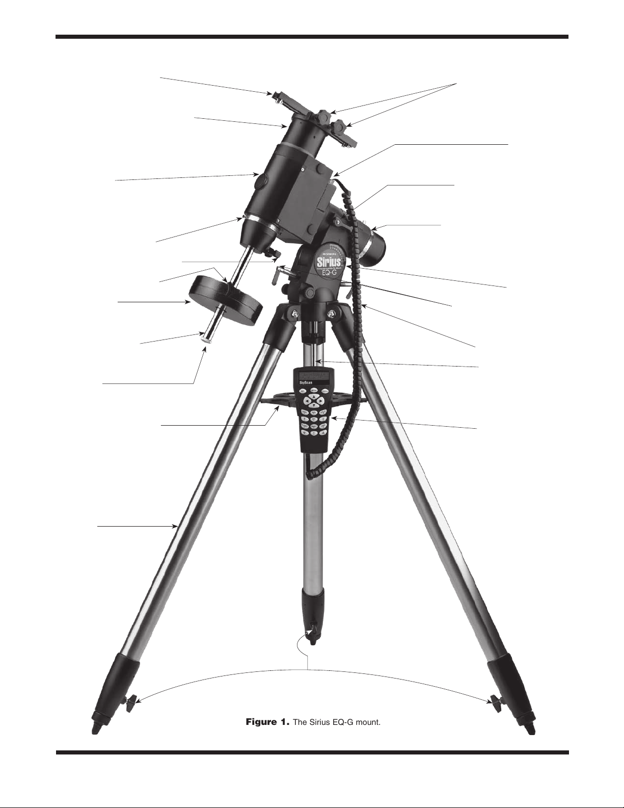
Tube ring mounting plate
Declination lock lever (not shown)
Mounting plate lock knobs
Control panel
Front opening
Declination setting circle
Counterweight shaft lock lever
Counterweight lock knob
Counterweight
Counterweight shaft
“Toe-saver”
Tripod center support tray
Right ascension lock lever
Right ascension setting circle
Latitude scale
Latitude adjustment L-bolts
Hand controller cable
Center support shaft
GoTo hand controller
Tripod leg
2
Leg lock levers
Figure 1.
The Sirius EQ-G mount.
Page 3
Congratulations on your purchase of a quality Orion mount. Your new Sirius EQ-G mount works with many different
optical tubes. Designed for astronomical use, the Sirius EQ-G provides a solid, stable foundation for precise navigation of the
night sky. The internally-housed, dual-axis stepper motors provide smooth slewing and tracking of any celestial object. With a
little practice, you’ll find that the Sirius EQ-G mount is an invaluable tool for getting the most out of your astronomical observing
sessions.
These instructions will help you set up and properly use your equatorial mount. Please read them over thoroughly before getting
started.
Table of Contents
1. Unpacking............................ 3
2. Parts List............................. 3
3. Assembly ............................ 3
4. Attaching a Telescope................... 4
5. Balancing a Telescope .................. 4
6. Setting Up and Using the Equatorial Mount . . 5
7. The Sirius EQ-G Dual-Axis Hand Controller.. 8
8. The Sirius EQ-G GoTo Hand Controller ....10
9. Specifications ........................ 20
10. Appendices......................... 21
1. Unpacking
The entire mount will arrive in three boxes, one containing
the tripod, one containing the equatorial mount and one containing the hand controller. Be careful unpacking the boxes.
We recommend keeping the boxes and original packaging.
In the event that the mount needs to be shipped to another
location, or returned to Orion for warranty repair, having the
proper packaging will ensure that your mount will survive the
journey intact.
Make sure all the par ts in the Parts List are present. Be
sure to check the box carefully, as some parts are small.
If anything appears to be missing or broken, immediately call Orion Customer Support (800-676-1343) or email
support@telescope.com for assistance.
If you’ve purchased the #7944 Dual-Axis hand controller:
Box 3: Dual-Axis Hand Controller
Qty. Item
1 Dual-Axis hand controller
2 Nylon hook-and-loop strips (1 hook strip, 1 loop
strip)
1 Wire clip
If you’ve purchased the #7947 GoTo hand controller:
Box 3: GoTo Hand Controller
Qty. Item
1 GoTo hand controller
1 GoTo hand controller cable for Sirius EQ-G
1 GoTo hand controller cable for Atlas EQ-G
1 GoTo hand controller bracket
1 Computer interface cable (RS-232)
1 Wire clip
3. Assembly
Refer to Figure 1 as needed during the assembly process.
1. Stand the tripod legs upright and spread the legs out as
far as they will go. Make certain that the leg lock levers
are tightened. Keep the tripod legs at their shortest (fully
retracted) length, for now; you can extend them to a more
desirable length later, after the mount is fully assembled.
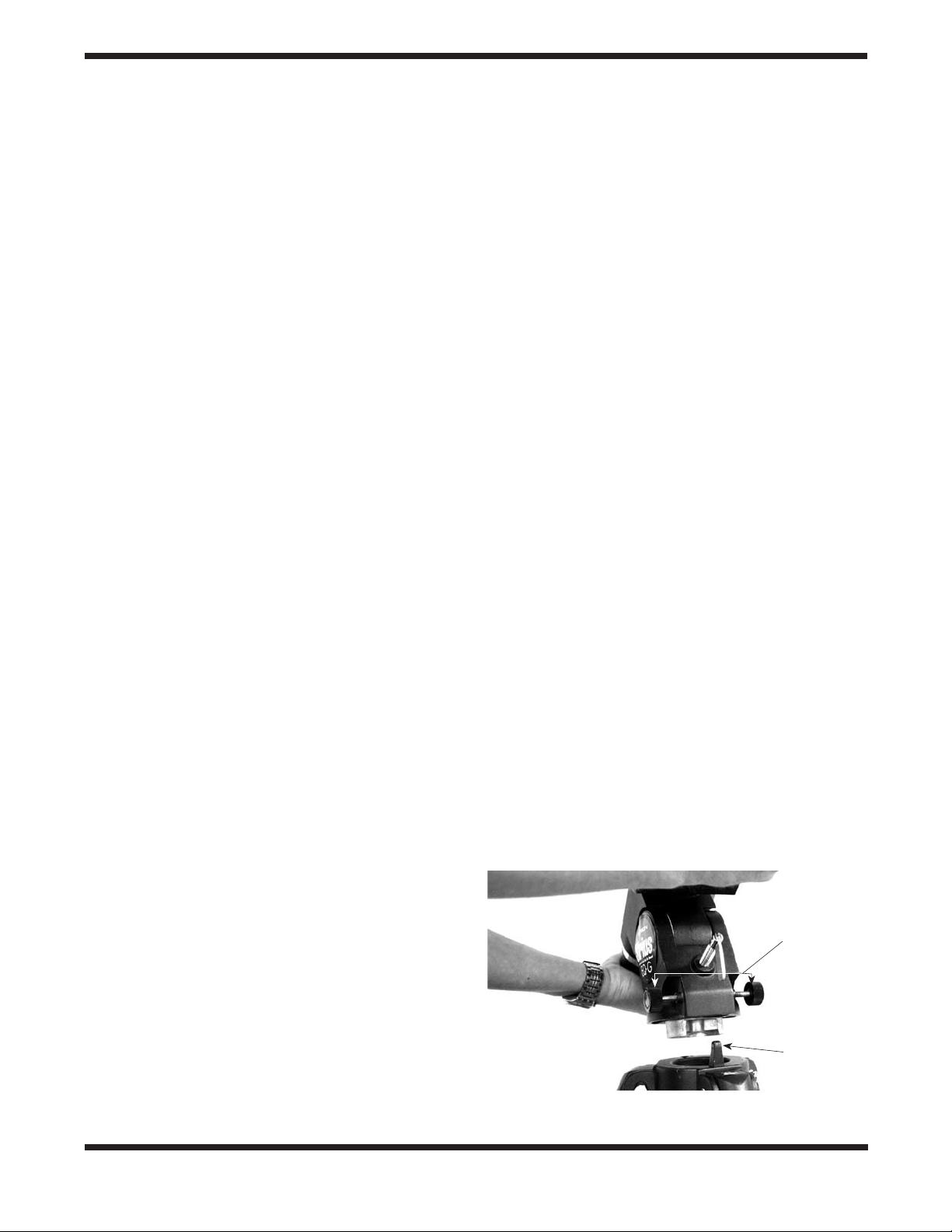
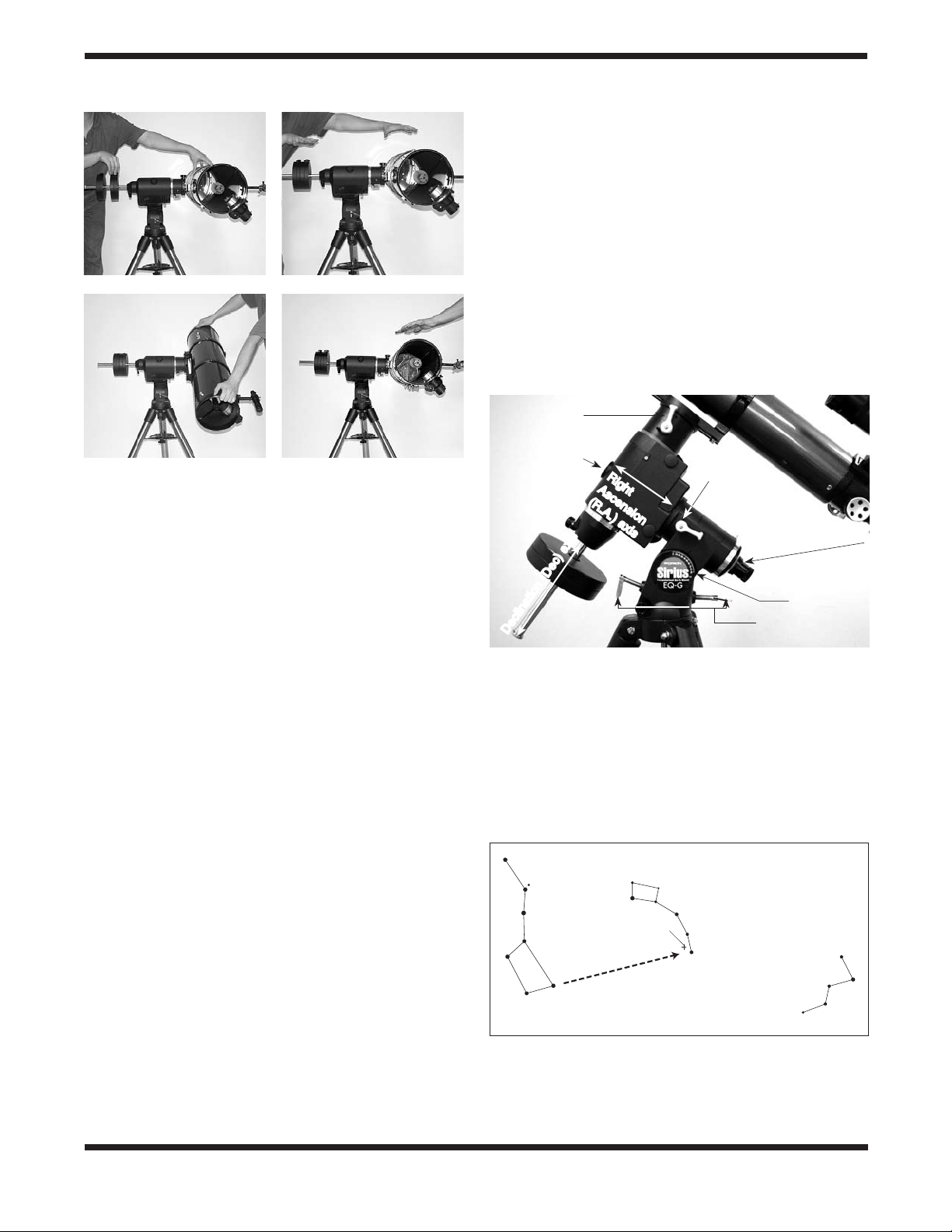
2. Place the base of the equatorial mount onto the tripod
head. Orient the equatorial mount so that the post on the
tripod head lines up with the azimuth adjustment knobs on
the equatorial mount (Figure 2). You may need to loosen
2. Parts List
Box 1: Tripod
Qty. Item
1 Tripod
1 Counterweight (11lbs.)
1 Tripod center support tray
Box 2: Equatorial Mount
Qty. Item
1 Equatorial mount
1 Tube ring mounting plate
1 12V DC Power cable
Azimuth
adjustment
knobs
Post
Figure 2.
lines up with the azimuth adjustment knobs on the equatorial mount.
Orient the equatorial head so the post on the tripod
3
Page 4
the azimuth adjustment knobs on the equatorial mount in
order to fit the mount onto the tripod head.
3. Thread the central support shaft up through the tripod
head and into the bottom of the equatorial mount until
tight. Use the upper knob on the central support shaft to
do this. The equatorial mount should now be firmly connected to the tripod.
4. Remove the knob and washer from the bottom of the
center support shaft. Slide the tripod support tray up the
bottom of the central support shaft until the three tray
arms are touching the legs of the tripod. The flat side of
the support tray should be facing up. Make sure the “V” of
each tray arm is against a tripod leg. Place the washer on
the center support shaft against the tray, and follow it by
threading the knob all the way up the center support shaft
until it is tight against the tray. The tripod support tray provides additional stability for the tripod, and holds up to five
1.25" eyepieces and two 2" eyepieces.
5. Loosen the counterweight shaft lock lever and fully extend
the counterweight shaft. Retighten the lock lever.
6. Remove the knurled “toe saver” retaining screw on the bottom of the counterweight shaft and slide the counterweight
onto the shaft. Make sure the counterweight lock knob is
adequately loosened to allow the counterweight shaft to
pass through the hole. Position the counterweight about
halfway up the shaft and tighten the lock knob. Replace
the toe saver at the end of the bar. The toe saver prevents
the counterweight from falling on your foot if the lock knob
happens to come loose.
Your Sirius EQ-G mount is now fully assembled and should
resemble Figure 1 except for the hand controller, which will
be installed and explained in Section 7 (Dual-Axis) or Section
8 (GoTo).
4. Attaching a Telescope
The Sirius EQ-G equatorial mount is designed to hold telescope tubes weighing up to approximately 25 lbs. For heavier
telescopes, the mount may not provide sufficient stability for
steady imaging. Any type of telescope can be mounted on the
Sirius EQ-G, including refractors, Newtonian reflectors, and
catadiotropics, provided a set of tube rings is available to couple the tube to the mount. Orion sells a variety of telescope
tube rings. Please visit our website at OrionTelescopes.com
for details.
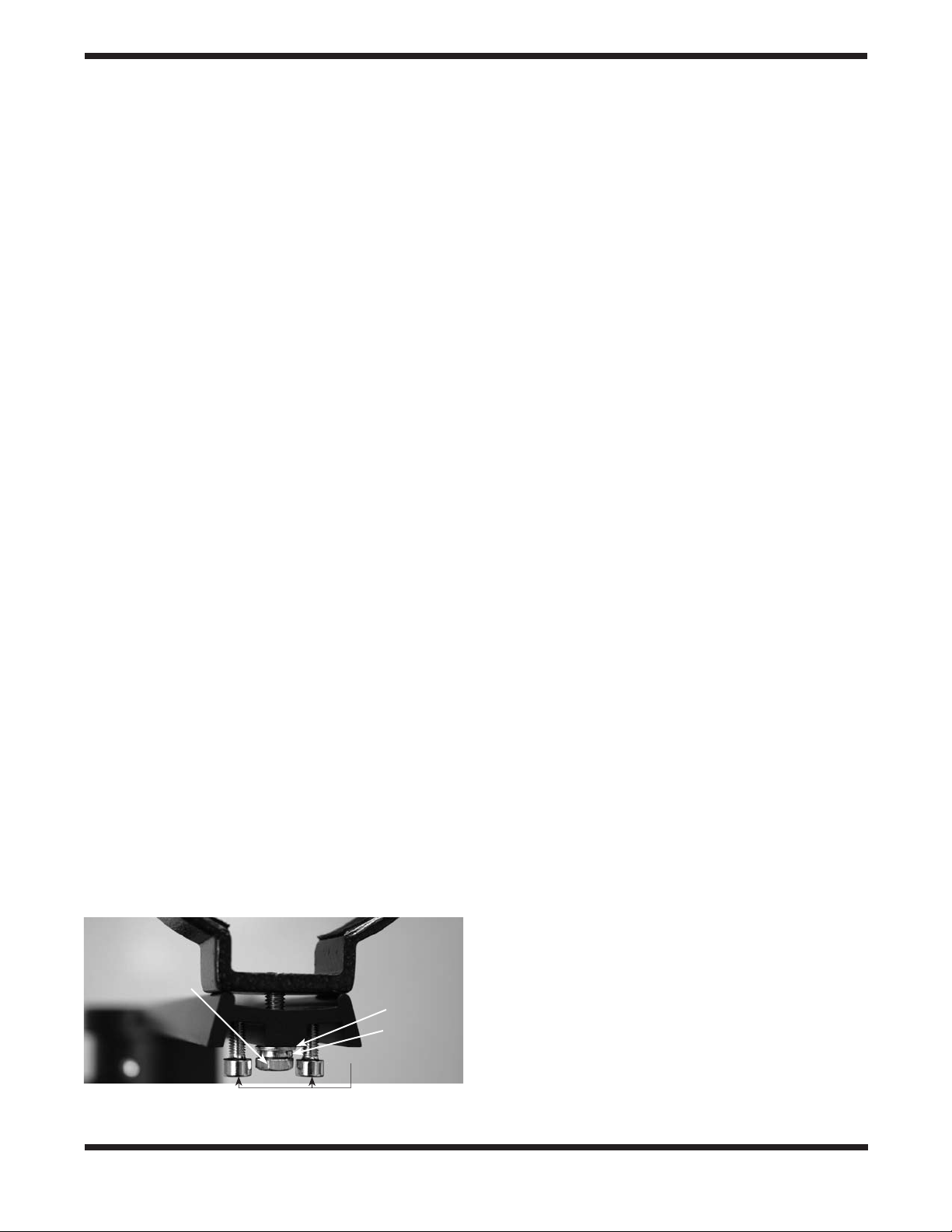
Tube ring
attachment screw
Flat washer
Lock washer
Optical axis offset
adjustment screws
Figure 3.
The tube ring mounting plate.
1. Attach the tube mounting rings to the tube ring mounting
plate using the screws that come with the tube rings. The
screws should go through the center holes in the ends of
the mounting plate and rethread into the tube rings. Note
that the side of the mounting plate with the central “groove”
will be facing up (Figure 3). Use a small wrench to secure
the tube rings to the mounting plate.
Note: The tube ring mounting plate included with the Sirius
EQ-G includes four optical axis offset adjustment screws;
these are the socket head cap screws located at each corner of the mounting plate. These adjustment screws will be
explained further in Appendix A. For now, confirm that all four
adjustment screws are sufficiently unthreaded so that the
ends of their threaded shafts are flush with the top surface of
the tube ring mounting plate.
Note: The optical axis offset adjustment screws should be
oriented so that the threaded shaft extends upward through
the top surface of the tube ring mounting plate. If the tube
ring mounting plate arrives with the optical axis offset screws
installed backwards, reverse their orientation before proceeding (Figure 3).
2. Loosen the black mounting plate lock knobs on the top of
the equatorial mount. Place the mounting plate, with the
tube rings attached, in the slot on top of the equatorial
mount. Position the mounting plate so that it is centered in
the slot. Re-tighten the mounting plate lock knobs until the
plate is secure.
3. Open the tube rings by unthreading the knurled clamps
and lay the telescope optical tube in the rings at about
the midpoint of the tube’s length. Rotate the tube so that
the focuser is at a convenient height for viewing. Close the
tube rings and retighten the clamps.
Note: Some telescope optical tubes (specifically SchmidtCassegrains and Maksutov-Cassegrains) have a mounting
plate connected directly to the tube. For these telescopes,
optional tube rings are not required. Simply follow step 2
(above) to connect the telescope to the mount.
5. Balancing a Telescope
To ensure smooth movement of a telescope on both axes of
the equatorial mount, it is imperative that the optical tube is
properly balanced. We will first balance the telescope with
respect to the right ascension (R.A.) axis, then the declination
(Dec.) axis.
1. Keeping one hand on the telescope optical tube, loosen
the R.A. lock lever. Make sure the Dec. lock lever is locked,
for now. The telescope should now be able to rotate freely
about the right ascension axis. Rotate it until the counterweight shaft is parallel to the ground (i.e., horizontal).
2. Now loosen the counterweight lock knob and slide the
weight along the shaft until it counterbalances the telescope (Figure 4a). That’s the point at which the shaft
remains horizontal even when you let go with both hands
(Figure 4b). If the telescope refuses to balance then you
4
Page 5
a. b.
6. Setting Up and Using the
Equatorial Mount
When you look at the night sky, you no doubt have noticed
that the stars appear to move slowly from east to west over
time. That apparent motion is caused by the Earth’s rotation
(from west to east). An equatorial mount (Figure 5) is designed
to compensate for that motion, allowing you to easily “track”
the movement of astronomical objects, thereby keeping them
from drifting out of your telescope’s field of view while you’re
observing.
This is accomplished by slowly rotating the telescope on its
right ascension (R.A.) axis, using the built in motor drive. But
first the R.A. axis of the mount must be aligned with the Earth’s
rotational (polar) axis—a process called polar alignment.
Dec lock lever
c.
d.
Figure 4a-d. Proper operation of the equatorial mount requires
that the telescope tube be balanced on the R.A. and Dec. axes. (a)
With the R.A. lock lever released, slide the counterweight down the
counterweight shaft until it just counterbalances the telescope tube.
(b) When you let go with both hands, the tube should not drift up or
down. (c) With the Dec. lock lever released, loosen the tube ring lock
clamps a few turns and slide the telescope forward or back in the
tube rings. (d) When the tube is balanced about the Dec. axis, it will
not move when you let go.
have either too much or too little counterweight. Remove
counterweight, or add optional counterweights if needed.
3. Retighten the counterweight lock knob. The telescope is
now balanced on the right ascension axis.
4. To balance the telescope on the declination axis, first tighten the R.A. lock lever, with the counterweight shaft still in
the horizontal position.
5. With one hand on the telescope optical tube, loosen the
Dec. lock lever. The telescope should now be able to rotate
freely about the declination axis.
6. Loosen the knurled ring clamps on the tube rings a few
turns, until you can slide the telescope tube forward and
back inside the rings (this can be aided by using a slight
twisting motion on the optical tube while you push or pull
on it) (Figure 4c). If the mounting plate is connected directly
to your telescope’s tube (i.e. tube rings are not utilized), you
can balance the telescope in Dec. by sliding the mounting
plate forward or back in the slot on top of the equatorial
mount.
7. Position the telescope in the tube rings so it remains horizontal when you carefully let go with both hands. This is the
balance point for the optical tube with respect to the Dec.
axis (Figure 4d).
8. Retighten the knurled ring clamps.
The telescope is now balanced on both axes. When you loosen the lock lever on one or both axes and manually point the
telescope, it should move without resistance and should not
drift from where you point it.
Front opening
Right
Ascension
(R.A.) axis
Declination (Dec) axis
R.A. lock lever
Polar axis finder scope
Latitude scale
Latitude adjustment
L-bolts
Figure 5. The Sirius EQ-G mount.
Polar Alignment
For Northern Hemisphere observers, approximate polar alignment is achieved by pointing the mount’s right ascension axis
at the North Star, or Polaris. It lies within 1° of the north celestial pole (NCP), which is an extension of the Earth’s rotational
axis out into space. Stars in the Northern Hemisphere appear
to revolve around the NCP.
Little Dipper
(in Ursa Minor)
Big Dipper
(in Ursa Major)
Pointer
Stars
N.C.P.
Polaris
Cassiopeia
Figure 6. To find Polaris in the night sky, look north and find the
Big Dipper. Extend an imaginary line from the two “Pointer Stars” in
the bowl of the Big Dipper. Go about five times the distance between
those stars and you'll reach Polaris, which lies within 1° of the north
celestial pole (NCP).
5
Page 6
To find Polaris in the sky, look north and locate the pattern of
the Big Dipper (Figure 6). The two stars at the end of the “bowl”
of the Big Dipper point right to Polaris.
Observers in the Southern Hemisphere aren’t so fortunate to
have a bright star so near the south celestial pole (SCP). The
star Sigma Octantis lies about 1° from the SCP, but it is barely
visible with the naked eye (magnitude 5.5).
For general visual observation, an approximate polar alignment is sufficient.
1. Level the equatorial mount by adjusting the length of the
three tripod legs.
2. There are two latitude adjustment L-bolts (see Figure 5);
loosen one while tightening the other. By doing this you
will adjust the latitude of the mount. Continue adjusting the
mount until the pointer on the latitude scale is set at the
latitude of your observing site. If you don’t know your latitude, consult a geographical atlas to find it. For example, if
your latitude is 35° North, set the pointer to 35. The latitude
setting should not have to be adjusted again unless you
move to a different viewing location some distance away.
3. Loosen the Dec. lock lever and rotate the telescope’s optical tube until it is parallel with the right ascension axis, as it
is in Figure 5.
4. Move the tripod so the telescope tube and right ascension axis point roughly at Polaris. If you cannot see Polaris
directly from your observing site, consult a compass and
rotate the tripod so the telescope points north.
The equatorial mount is now polar aligned for casual observing.
More precise polar alignment is recommended for astrophotography. For this we recommend using the polar axis finder
scope.
From this point on in your observing session, you should not
make any further adjustments to the latitude of the mount, nor
should you move the tripod. Doing so will undo the polar alignment. The telescope should be moved only about its R.A. and
Dec. axes.
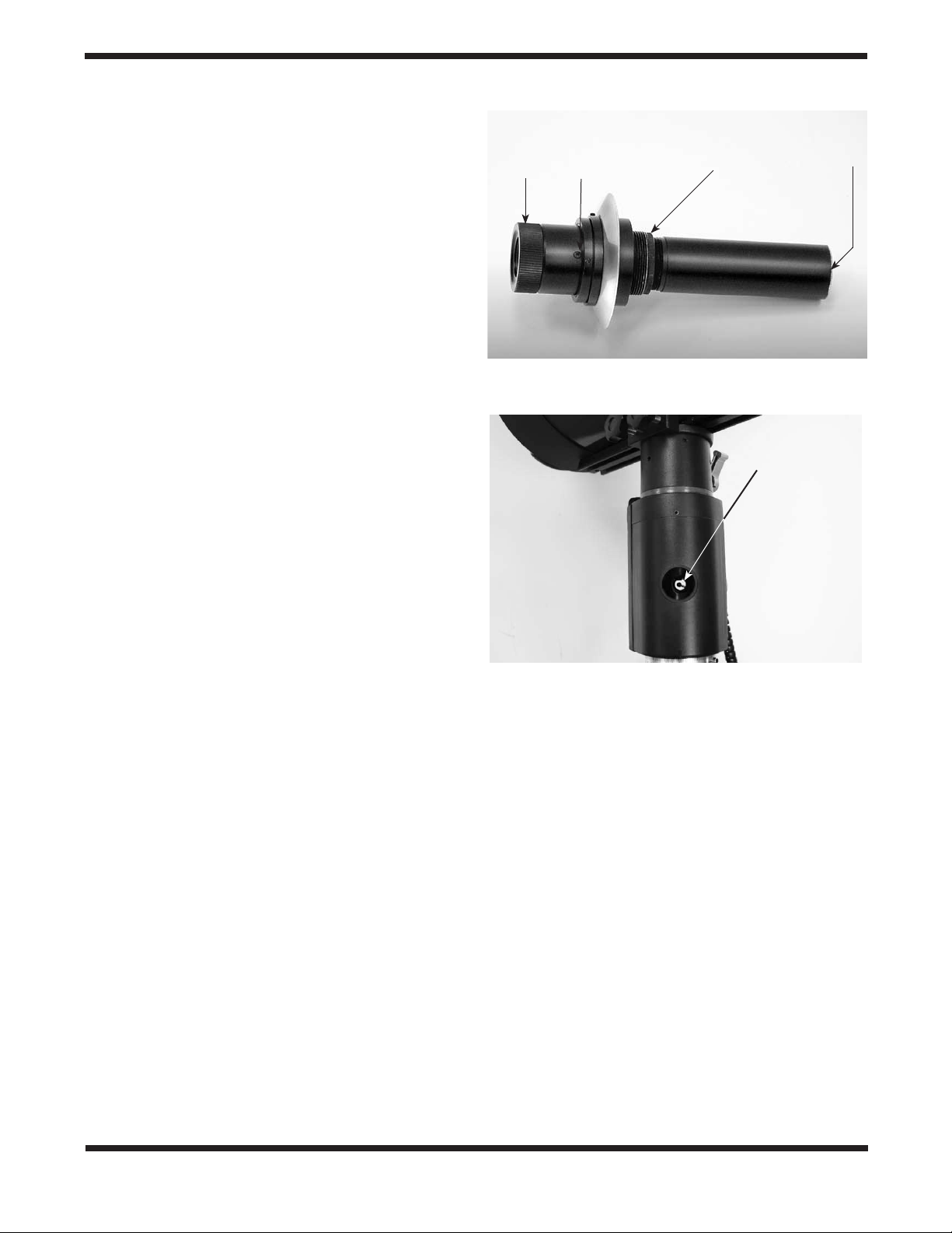
The Polar Axis Finder Scope
The Sirius EQ-G mount comes with a polar axis finder scope
(Figure 7) housed inside the right ascension axis of the mount.
When properly aligned and used, it makes accurate polar
alignment quick and easy to do. Unthread the cover at the rear
of the mount’s right ascension axis and remove the cap on
the front opening of the equatorial mount (Figure 5) to view
through the polar axis finder scope.
Alignment of the Polar Axis Finder Scope
1. Loosen the Dec. lock lever and rotate the optical tube on
the declination axis until you have a clear view through the
polar axis finder scope (Figure 8). Tighten the Dec. lock
lever.
2. Look through the polar finder at a distant object (during the
day) and center it in the crosshairs. You may need to adjust
the latitude adjustment L-bolts and the tripod position to do
this. Focus the polar finder by rotating the eyepiece.
Eyepiece
focus ring
Alignment
setscrew (3)
Focus
lock ring
Objective
lens
Figure 7. The polar axis finder scope.
Objective lens
of polar axis
finder scope
Figure 8. The optical tube must be rotated about the Dec. axis
until you have a clear view along the R.A. axis with the polar axis
finder scope.
3. Rotate the mount 180° about the R.A. axis. It may be convenient to remove the counterweights and optical tube
before doing this.
4. Look through the polar finder again. Is the object being
viewed still centered on the crosshairs? If it is, then no further adjustment is necessary. If not, then look through the
polar finder while rotating the mount about the R.A. axis.
You will notice that the object you have previously centered
moves in a circular path. Use the three alignment setscrews on the polar axis finder (Figure 7) to redirect the
crosshairs of the polar finder to the apparent center of this
circular path.
5. Repeat this procedure until the position the crosshairs point
to does not rotate off-center when the mount is rotated in
R.A.
The polar axis finder scope is now ready to be used. When not
in use, replace the plastic protective cover to prevent the polar
finder from getting bumped.
6
Page 7
Using the Polar Axis Finder Scope
The reticle of the polar axis finder scope for the Sirius EQ-G
has a tiny star map printed on it that makes precise polar alignment quick and easy. To polar align the mount using the polar
axis finder scope, follow these instructions:
1. Approximately polar-align the mount as outlined in the procedure above.
2. Loosen the Dec. lock lever and rotate the optical tube on
the declination axis until you have a clear view through
the polar axis finder scope along the right ascension axis
(Figure 8). Tighten the Dec. lock lever.
3. Focus the polar finder by rotating the eyepiece. Now, sight
Polaris in the polar axis finder scope. If you have followed
the approximate polar alignment procedure accurately,
Polaris will probably be within the field of view. If not, move
the tripod left-to-right, and adjust the latitude up-and down
until Polaris is somewhere within the field of view of the
polar axis finder scope.
Note: If you do not have a clear view of Polaris from your
observing site, you will not be able to use the polar axis finder
to precisely polar align the telescope.
4. The mount has a built-in illuminator that allows you to see
the reticle pattern in the polar axis finder scope at night.
Simply turn on the power switch on the Sirius EQ-G mount
(see “Powering the Sirius EQ-G Mount”) and the polar axis
finder scope reticle will be illuminated. Note the constellation Cassiopeia and the Big Dipper in the reticle. They
do not appear in scale, but they indicate the general positions of Cassiopeia and the Big Dipper relative to the North
Celestial Pole (which is indicated by the cross at the center of the reticle). Rotate the reticle so the constellations
depicted match their current orientation in the sky when
viewed with the naked eye. To do this, release the R.A. lock
lever and rotate the main telescope around the R.A. axis
until the reticle is oriented with sky. For larger optical tubes,
you may need to remove the tube from the mount to prevent it from bumping into the mount. Once the reticle is correctly oriented, use the right ascension lock lever to secure
the mount’s position.
5. Now use the azimuth adjustment knobs (Figure 2) and the
latitude adjustment L-bolts (Figure 5) on the mount to position the star Polaris inside the tiny circle marked “Polaris”
on the finder’s reticle. You must first loosen the knob underneath the equatorial mount on the center support shaft to
use the azimuth adjustment knobs. Once Polaris is properly
positioned within the reticle, you are precisely polar aligned.
Retighten the knob underneath the equatorial mount.
From this point on in your observing session, you should not
make any further adjustments in the azimuth or the latitude
of the mount, nor should you move the tripod. Doing so will
undo the polar alignment. The telescope should be moved only
about its right ascension and declination axes.
Additional Note Regarding Focusing the Polar Axis Finder
Scope
The polar axis finder scope is normally focused by simple rotation of the eyepiece focus ring. However, if after adjusting the
focus ring you find that the image of the reticle is sharp, but
the stars are out of focus, then you must adjust the focus of
the polar axis finder’s objective lens. To do this, first remove
the polar axis finder from the mount by unthreading it. Look
through the polar axis finder at a star (at night) or distant object
at least 1/4 mile away (during daylight). Use the eyepiece focus
ring to bring the reticle into sharp focus. Now, loosen the focus
lock ring (Figure 7) and thread the entire objective end of the
finder inward or outward until images appear sharp. Re-tighten
the focus lock ring. Once the polar axis finder’s objective lens
is focused, it should not need to be adjusted again.
Confused About Pointing the Telescope?
Beginners occasionally experience some confusion about how
to point the telescope overhead or in other directions. In Figure
1 the telescope is pointed north as it would be during polar
alignment. The counterweight shaft is oriented downward. But
it will not look like that when the telescope is pointed in other
directions. Let’s say you want to view an object that is directly
overhead, at the zenith. How do you do it?
DO NOT make any adjustment to the latitude adjustment Lbolts. That will spoil the mount’s polar alignment. Remember,
once the mount is polar aligned, the telescope should be
moved only on the R.A. and Dec. axes. To point the scope
overhead, first loosen the R.A. lock lever and rotate the telescope on the right ascension axis until the counterweight shaft
is horizontal (parallel to the ground). Then loosen the Dec. lock
lever and rotate the telescope until it is pointing straight overhead. The counterweight shaft is still horizontal. Then retighten
both lock levers.
What if you need to aim the telescope directly north, but at an
object that is nearer to the horizon than Polaris? You can’t do
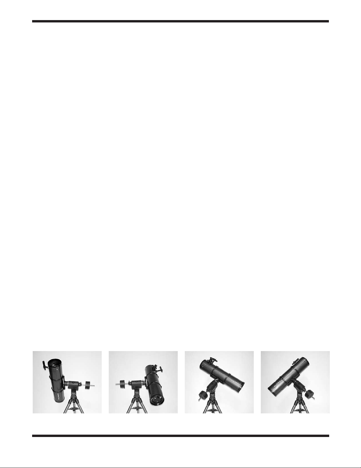
a. b. c. d.
Figure 9a-d.
that the tripod and mount have not been moved; only the telescope has been moved on the its R.A. and Dec. axes.
These illustrations show the telescope pointed in the four cardinal directions. (a) north, (b) south, (c) east, (d) west. Note
7
Page 8
it with the counterweights down as pictured in Figure 1. Again,
you have to rotate the scope in right ascension so that the
counterweight shaft is positioned horizontally. Then rotate the
scope in declination so it points to where you want it near the
horizon.
To point the telescope directly south, the counterweight shaft
should again be horizontal. Then you simply rotate the scope
on the declination axis until it points in the south direction.
To point the telescope to the east or west, or in other directions,
you rotate the telescope on its right ascension and declination axes. Depending on the altitude of the object you want to
observe, the counterweight shaft will be oriented somewhere
between vertical and horizontal.
Figure 9 illustrates how the telescope will look when pointed
at the four cardinal directions: north (Figure 9a), south (Figure
9b), east (Figure 9c) and west (Figure 9d).
The key things to remember when pointing the telescope are
that a) you only move it in right ascension and declination, not
in azimuth or latitude (altitude), and b) the counterweight and
shaft will not always appear as it does in Figure 1. In fact it
almost never will!
7. The Sirius EQ-G Dual-Axis
If you are using a portable battery like the Orion Dynamo, use
the supplied 12V DC power cable (male cigarette lighter plug
on one end, standard 12V DC power plug on the other end)
to connect the battery to the 12V DC power jack on the control panel of the mount (Figure 9.1). Make sure the Dynamo’s
power switch is in the “on” position after connecting.
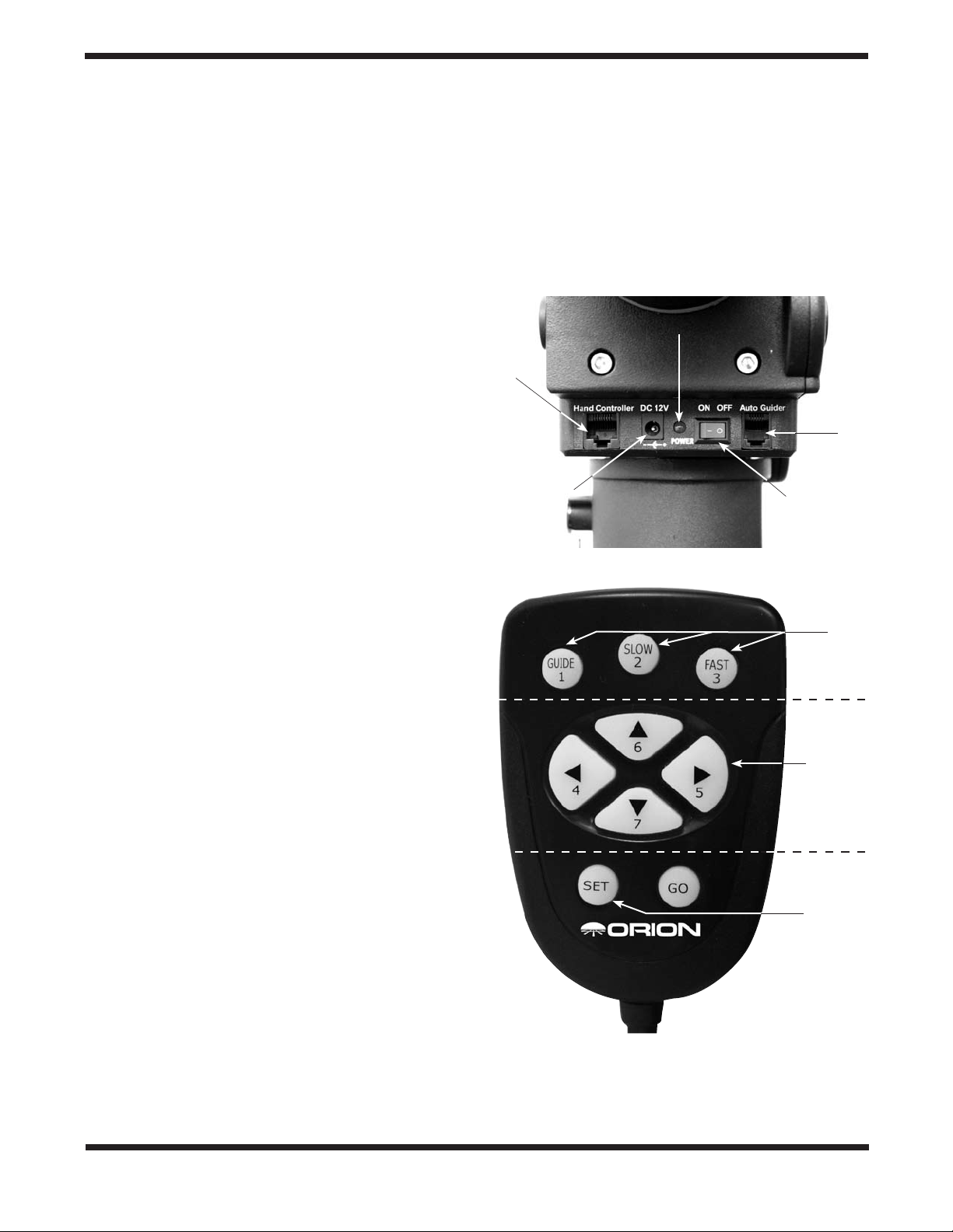
Note: The power indicator LED on the mount (near the power
switch) will begin to flash when the battery power is low. When
the battery power is extremely low, the LED will flash rapidly.
Recharge or replace the battery as needed.
Power indicator light
Hand
controller
jack
Autoguider
jack
12V DC power
jack
Power switch
Controller
The Sirius EQ-G with dual-axis hand controller will automatically track any celestial object as the Earth rotates. You can
also use the controller’s directional buttons to center objects
within your telescope’s finderscope or eyepiece. For imaging
purposes, the controller provides several guide speed rates so
a camera can be accurately guided during a long exposure.
Attaching the Dual-Axis Controller
The dual-axis controller has a cable with a modular connector
on one end. Plug the modular connector into the jack on the
control panel of the mount (Figure 9.1) until it clicks into place.
The nylon hook-and-loop strips have been provided so the
dual-axis hand controller can be placed in a convenient position on the mount when not in use. Place the “hooks” strip on
the back of the dual-axis hand controller, and the “loops” strip
on the mount in a convenient location. Make certain the location of the strip on the mount will not cause the dual-axis hand
controller to interfere with the motions of the mount or telescope.
You can reduce the chances of getting your hand controller,
power supply, or other cables tangled during use of the Sirius
EQ-G by using the included wireclip. The clip also reduces
mechanical strain on the cable. The wire clip is adhesive
backed for easy attachment to any convenient location on the
mount.
Figure 9.1. The Sirius EQ-G control panel.
Speed
buttons
Directional
buttons
Set button
Powering the Sirius EQ-G Mount
The Sirius EQ-G should be powered by a 12V DC power supply
(tip positive) capable of producing continuous current with a minimum of 2 amps. We recommend using a portable rechargeable
battery, like the Dynamo or Dynamo Pro available from Orion.
8
Figure 9.2. The Sirius EQ-G Dual Axis hand controller.
Functions of the Dual-Axis Hand Controller
There are three main categories of control buttons on the dualaxis controller (Figure 9.2):
Page 9

1. Speed buttons
2. Directional buttons
3. Set button
The dual-axis hand controller is equipped with a red LED light
in each button to indicate operation. An individual button’s LED
will illuminate when the button is pressed. If a button combination is entered, all LEDs will illuminate to indicate a successful
operation.
Speed Buttons
The three buttons located near the top of the dual-axis hand
controller (Guide, Slow, and Fast) are used to set the slewing
and guiding speed of the mount.
Directional Buttons
The directional buttons allow complete control of the mounted
telescope’s position during slewing or tracking. The Left and
Right directional buttons control movements about the right
ascension (R.A.). axis. The Up and Down directional buttons
control movements about the declination (Dec.) axis.
Set Button
The Set button is used to set the dual-axis hand controller to
operate in either Northern or Southern hemisphere locations.
Note: The Go button is not used in normal operation of the
dual-axis controller.
Tracking Objects with the Dual-Axis Hand
Controller
In order for your Sirius EQ-G mount to accurately track celestial objects as they appear to migrate across the night sky,
your mount must be properly polar aligned. For more details
on polar alignment, please consult section 6 of this manual.
Once the power switch is turned on, the dual-axis controller
begins to track by rotating the R.A. axis motor at the default
(sidereal) rate. The Dec. axis motor will not rotate. As long as
the mount has been properly polar aligned, it should not be
necessary to adjust the Dec. axis for accurate tracking. If you
notice a lack of tracking precision at the default (sidereal) rate,
consult section 6 of this manual and attempt to polar align the
mount more accurately.
Tracking can be deactivated or activated at any time the Sirius
EQ-G mount is receiving power. In order to deactivate tracking,
simply press and hold the Guide button then press the Slow
button on the controller. Pressing the same button combination
will reactivate tracking at the default (sidereal) rate.
There are three tracking rates used by the dual-axis controller:
Sidereal rate tracking is the default tracking rate for the Sirius
EQ-G mount. Celestial objects are tracked using this rate
which is equivalent to the rate of the Earth’s rotation.
Solar rate tracking is used to track the Sun over a long period
of time. Solar rate tracking is activated by pressing and holding
the Slow speed button, then the Right directional button.
Warning: Never look directly at the Sun through your telescope or its finder scope, even for an instant, without a
professionally made solar filter that completely covers the
front aperture of the instrument, or permanent eye damage could result. Young children should use this telescope
only with adult supervision.
Lunar rate tracking is used to track the Moon at its rate of
apparent motion across the sky. Lunar rate tracking is activated by pressing and holding the Slow button, then the Down
directional button.
Note: Solar and Lunar tracking rates can only be used when
the Sirius EQ-G has tracking activated. If tracking is deactivated, you must first activate tracking by holding the Guide button
then pressing the Slow button.
Setting the Slewing Speed
In order to conveniently center an object in your telescope’s
finderscope or eyepiece, you can set the speed rate at which
the motors rotate the telescope when the directional buttons
are pressed. The three speed buttons located near the top of
the hand controller are used to set the slewing rates of the
mount.
The slewing speed buttons each have two different speeds
assigned to them. The slewing speed that is employed is
dependent on whether or not the dual-axis controller has tracking activated or deactivated (by holding the Guide button then
pressing the Slow button).
With tracking activated, the Guide button will slew the Sirius
EQ-G mount at a very slow speed equals to 1.5x sidereal rate.
This speed rate will generally be used to guide a telescope
while imaging with a camera. You can also change the Guide
button speed rate to be slightly faster or slower (see “Setting
the Guiding Speed”). If tracking is deactivated, pressing the
Guide button will set the Sirius EQ-G to slew at 32x sidereal
rate; this speed is too fast for guiding during imaging.
By pressing the Slow button with tracking activated, the Sirius
EQ-G will slew at 4x sidereal rate. With tracking deactivated,
pressing the Slow button will set the Sirius EQ-G mount to
slew at 64x sidereal rate.
With tracking activated, the Fast button will set the Sirius EQG mount to slew at 8x sidereal rate. If tracking is not activated,
pressing the Fast button will set the Sirius EQ-G to slew at
800x sidereal rate; this is a very fast speed that can be used to
slew the mount from object to object across the sky.
Changing the Guiding Speed
The dual-axis hand controller provides 4 different guiding
speed settings: 2x, 1.75x, 1.5x (default), and 1.25x sidereal
rate. If you change the guiding speed from the default setting
of 1.5x sidereal rate, the controller will guide at the chosen
speed until another guiding speed is selected.
9
Page 10

In order to set the guiding speed of your Sirius EQ-G, use the
following button combinations:
•2xsiderealrate: Hold the Fast button, then press
the Up directional button.
•1.75xsiderealrate: Hold the Fast button, then press
the Left directional button.
•1.5xsiderealrate: Hold the Fast button, then press
the Right directional button.
•1.25xsiderealrate: Hold the Fast button, then press
the Down directional button.
Reversing the Directional Buttons
Celestial objects appear to move through the sky differently
when viewed through telescopes and/or accessories of different designs. For example, if an object viewed through a
refractor appears to migrate towards the left-hand side of an
eyepiece’s field of view, it will appear to migrate towards the
right-hand side of an eyepiece’s field of view in a reflector
telescope.
In order to make viewing and tracking objects convenient,
regardless of telescope design, the dual-axis controller features a “reverse” function which reverses the direction of the
hand controller’s directional buttons. This way you can match
the directional button to the way the object actually moves in
the telescope eyepiece.
To reverse the direction of the Left and Right directional buttons, press and hold the Slow speed button then press the
Left directional button. To reverse the direction of the Up and
Down directional buttons, press and hold the Slow button
then press the Up directional button.
Once you have reversed the directional buttons, the dual-axis
controller will save the reversed settings until it they are manually changed again. Turning the power off will not affect the
directional button setting last entered.
Northern or Southern Hemisphere operation
The dual-axis hand controller is capable of operating in either
Northern or Southern Hemisphere viewing locations. The system is set up for Northern Hemisphere locations by default, so
if you are viewing from a Northern Hemisphere location, it is
not necessary to make any setting changes.
For the dual-axis controller to properly track celestial objects
in the Southern Hemisphere, press and hold the Down directional button and then press the Set button while powering
on the mount. Release the Set button after the mount has
successfully powered on and the Guide button begins flashing. The controller will now operate properly in the Southern
Hemisphere. You can switch back to Northern Hemisphere
mode by using the same button combination. As long as the
controller is operating in Southern Hemisphere mode, the Set
button will illuminate.
Power Conservation
In the interest of conserving the amount of power drawn by the
Sirius EQ-G mount, the Dec. motor will enter a “sleep” mode
if left idle for a period of 15 seconds. In “sleep” mode, the Dec.
motor stops completely and the amount of used power drops
by about 40%. To reactivate the Dec. motor, press the Up or
Down directional button.
Upgrading your Sirius EQ-G
While the dual-axis hand controller provides many useful
functions such as celestial object tracking and motorized
motion control, there is a GoTo hand controller for the Sirius
EQ-G available from Orion. The features and functions of the
GoTo hand controller are explained in the following section. If
you are interested in upgrading your Sirius EQ-G to a GoTo
system, call our Customer Service department at 800-6761343 or visit our website at www.OrionTelescopes.com for
more information.
8. The Sirius EQ-G GoTo
Hand Controller
The Sirius EQ-G mount equipped with the GoTo hand controller provide easy, computerized location of thousands of night
sky objects such as planets, nebulae, star clusters, galaxies,
and more for viewing through your telescope. The GoTo hand
controller and internal dual-axis motors allow you to automatically point your telescope at a specific object, or tour the skies
with pushbutton simplicity. The user-friendly menu allows
automatic slewing to over 13,400 objects. Even inexperienced
astronomers will find themselves quickly mastering the variety of features the GoTo hand controller offers in just a few
observing sessions.
Attaching the GoTo Hand Controller
The Sirius EQ-G GoTo hand controller comes with two cables;
one for usage with the Sirius EQ-G mount, while the other is
for use with the Atlas EQ-G mount. After installation, you will
have one of these cables left over. Feel free to discard this
cable, as it will not be needed.
The hand controller cable for the Sirius EQ-G has modular
connectors (RJ-45) on both ends. Plug the modular connector
on one end of the cable into the hand controller jack (Figure
10), and plug the modular connector on the other end of the
cable into the mount’s controller jack (Figure 11). Push the
connectors into the jacks until they click into place.
10
Page 11

Hand controller
jack
Computer interface
jack
12V DC power jack
Figure 10. Hand controller jacks.
The smaller modular jack on the hand controller (Figure 10)
is used for RS-232 communications between the Sirius EQ-G
mount and a computer equipped with astronomy software like
Starry Night Pro (see “Linking with a Computer”). The 12V DC
power jack on the hand controller allows independent use of
the GoTo hand controller for users who wish to browse the
object database without connecting to the telescope mount
(Figure 10). The power jack is also used when updating the
firmware in the hand controller (see “Updating the GoTo Hand
Controller’s Firmware”).
The included GoTo hand controller bracket attaches to the
built-in notch in the tripod center support tray. To install the
hand controller bracket, simply line up the tab on the back of
the bracket with the notch in the tripod center support tray and
slide the bracket forward until it clicks into place (Figure 12).
You now have a place to put the GoTo hand controller while
you are viewing.
You can reduce the chances of getting your hand controller
cable tangled during use by installing the included wire clip.
The clip also prevents mechanical strain on the hand controller cable when it is in use. The wire clip is adhesive backed for
easy attachment to any convenient location on the mount.
Power indicator light
Hand
controller
jack
Autoguider
jack
12V DC power
jack
Power switch
Figure 11. The Sirius EQ-G control panel
Powering the Sirius EQ-G Mount
The Sirius EQ-G should be powered by an 11V to 15V DC
power supply (tip positive) capable of producing continuous
current of a minimum 2 amps. We recommend using a por-
Notch
Tripod center
support tray
Hand controller
bracket
Figure 12. Installing the hand controller bracket.
table rechargeable battery, like the Dynamo or Dynamo Pro
available from Orion.
If you are using a portable battery like the Orion Dynamo, use
the 12V DC power cable supplied with your mount (male cigarette lighter plug on one end, standard 12V DC power plug on
other end) to connect the battery to the 12V DC power jack on
the mount (Figure 11). Make sure the Dynamo’s power switch
is in the “on” position after connecting. Then, to turn the mount
(and GoTo hand controller) on, simply press the power switch
on the mount so it is in the “on” position.
Note: The power indicator LED on the mount (near the power
switch) will begin to flash when the battery power is low. When
the battery power is extremely low, the LED will flash rapidly.
Recharge or replace the battery as needed.
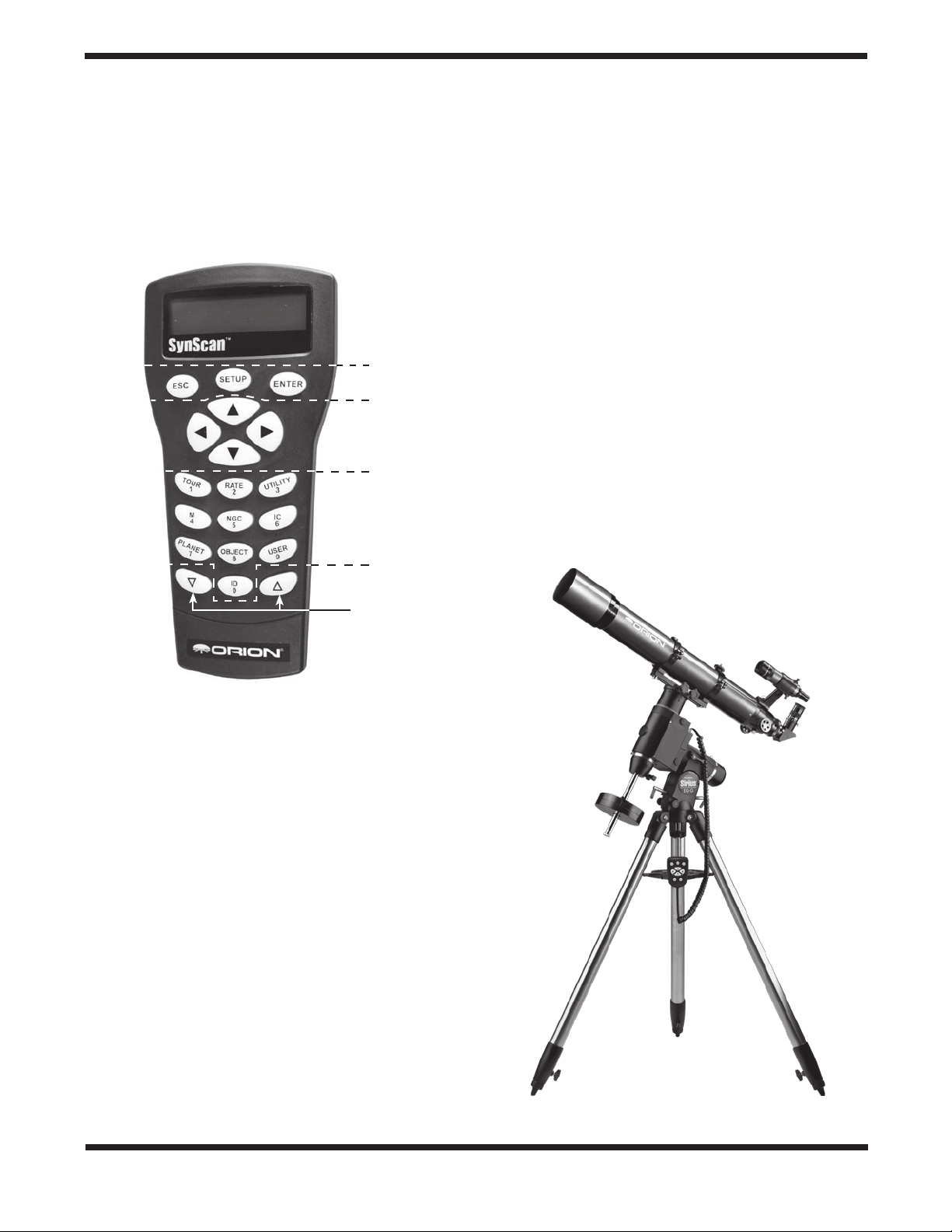
Functions of the GoTo Hand Controller
There are four main categories of control buttons on the GoTo
hand controller (Figure 13):
1. Mode buttons
2. Directional buttons
3. Scroll buttons
4. Dual Purpose buttons
Mode Buttons
The three mode buttons are located at the top of the controller, directly below the LCD screen. They include the ESC,
ENTER, and SETUP buttons.
The ESC button is used to escape from a certain command or
go back a level in the menu tree.
The ENTER button is used to select the functions and submenus in the menu tree, and to confirm certain functional
operations.
The SETUP button is a “hot key” that takes you to the Setup
Menu.
Directional Buttons
The directional buttons allow the user to have complete motion
11
Page 12
control of the Sirius EQ-G mount at almost any step in operation. These controls are locked out when the mount is slewing
to an object. The directional buttons are very helpful when
initially aligning the mount, centering objects in the eyepiece
field of view, and manual guiding. The directional buttons are
typically used in conjunction with the RATE button. The left
and right directional buttons can also be used to move the text
cursor when entering data into the hand controller.
NGC, IC, M, Planet, and Object buttons: Allow direct access
to catalogs and databases of over 13,400 objects.
GoTo Hand Controller
Operation
This section provides a guide for initial setup and alignment of
the Sirius EQ-G mount with the GoTo hand controller.
Figure 13. The GoTo hand controller.
Display screen
Mode buttons
Directional
buttons
Dual purpose
buttons
Scroll buttons
Initial Setup
1. Perform the polar alignment using the procedure previously outlined in Section 6 of the instruction manual. A
rough polar alignment will suffice, but an accurate polar
alignment using the polar axis finder scope will increase
tracking accuracy (and pointing accuracy for one-star
alignments).
2. Rotate the telescope tube about the mount’s declination
axis so the tube is parallel with the mount’s R.A. axis (and
the front of the tube is pointed to the sky, not the ground).
Rotate the mount’s R.A. axis so the counterweight shaft is
pointed straight down. The telescope and mount should
now appear as shown in Figure 14. This will be called the
“home” position of the mount.
Note: Once the mount is initially set to its “home” position, the
mount should not be moved manually. Otherwise, the GoTo
Scroll Buttons
The up and down scroll buttons allow you to scroll up and
down within the menu tree or selections displayed on the
hand controller screen.
Dual Purpose Buttons
The dual purpose buttons serve two distinct purposes. They
are used for data entry and as quick reference keys.
TOUR button: Takes you on a preset tour of the best night sky
objects visible
RATE button: Changes the speed of the motors when the
directional buttons are pressed. There are 10 speeds to
choose from, with 0 being the slowest and 9 being the fastest.
UTILITY button: Provides “hot key” access to the Utility
Functions menu.
USER button: Enter or recall coordinates for up to 25 objects
in the User Defined database.
ID button: Identifies the object the mount is currently pointing
to.
12
Figure 14. The telescope and mount in their “home” position
Page 13

hand controller will lose track of the mount’s position, and the
alignment procedure will need to be performed again. Keep
both the R.A. and Dec. lock levers engaged.
3. Turn on the power switch on the mount
4. The initial screen displayed on the hand controller is the
version screen. Press ENTER to proceed.
5. The hand controller’s LCD screen will show a safe solar
viewing warning message. Press the ESC button to continue.
Note: The GoTo hand controller’s LCD backlighting will
become dim and the illuminated buttons will turn off if left idle
for 30 seconds. Pressing any button will re-illuminate the hand
controller.
6. Enter your observing site’s longitude and latitude coordinates. First enter the longitude coordinate and hemisphere,
followed by the latitude coordinate and hemisphere. Use
the numerical keypad to enter the digits, and use the left
and right directional buttons to move to the next digit. Use
the scroll buttons to choose W or E (for longitude) and N
or S (for latitude). If you do not know the longitude and
latitude coordinates of your viewing location, consult an
atlas or geographical map of your area. Press ENTER to
confirm your coordinates.
Note: Longitude and latitude coordinates must be entered
in degrees and arcminutes. If your map or atlas gives coordinates in decimal values (i.e. latitude = 36.95 N) you must
convert into degrees and arcminutes (i.e. latitude 36.95 N =
latitude 36°57’ N).
Note: If a mistake is entered into the hand controller during
the initial setup procedure, press the ESC button to go back
to the previous screen.
7. Enter the time zone in which you are observing in hours
(see Appendix D) using the scroll buttons (+ for east of
Prime Meridian, - for west of Prime Meridian) and numeric
keypad. Use the left and right directional buttons to move
to the next digit. Press ENTER to confirm your choice.
8. Enter the date in mm/dd/yyyy format using the numeric
keypad. Use the left and right directional buttons to move
to the next digit. Press ENTER to confirm your choice.
9. Enter your current local time using the 24 hour clock format (example: 2:00PM = 14:00). Press ENTER to view the
time you entered. If the time is incorrect, press ESC to go
back to the previous screen. If the time is correct, press
ENTER again.
10. If the date entered in step 8 falls between March
and November, the hand controller will ask “DAYLIGHT
SAVING?” on the LCD screen. Use the scroll buttons to
select “YES” or “NO” to indicate if you are currently on
Daylight Savings Time or not, and press ENTER.
11. The hand controller will now display “Begin Alignment?”
Press 1 or ENTER to start the alignment procedure. Press
2 or ESC to skip the alignment and exit to the Main Menu.
You are now ready to begin the alignment procedure.
Alignment
In order for the GoTo hand controller to accurately locate and
point to objects in the sky, it must first be aligned on known
positions (stars). With the supplied information, the controller
can replicate a model of the sky and the movements of astronomical objects.
There are three ways to align depending on your demand for
accuracy. If you are using the GoTo controller for the first time,
we recommend you begin with the three-star alignment. In
most cases, a three-star alignment produces the most accurate alignment among the three methods. The description
below will lead you through a step-by-step procedure on how
to perform the three-star alignment.
Note: Before performing any of the alignment methods, be
sure your finderscope is well aligned with the telescope tube.
Three-Star Alignment
1. From the alignment screen, select “3-Star Align” using the
scroll buttons. Press ENTER to confirm your choice.
2. The hand controller will provide a list of stars available in
your current sky for you to choose as the first alignment
star. Choose a star you are familiar with using the scroll
buttons. Press ENTER to confirm your choice. The mount
will start slewing the telescope towards the chosen object.
When the telescope stops slewing, adjust its position
using the controller’s directional buttons until the chosen
star is centered on the crosshairs of the finderscope. Now
look in the eyepiece and adjust the position of the telescope (again using the directional buttons) so the chosen
star is centered in the field of view of the eyepiece. Press
ENTER to confirm the star is centered .
Note: The slewing speed can be adjusted by pressing the
RATE button. Choose a desired rate between 0 (slowest) and
9 (fastest).
Note: The hand controller will make a “beep” sound once it
has finished slewing to an object. Do not try to adjust the telescope before you hear the “beep” sound. The controller will
only respond to the ESC button while slewing (which stops
the slewing).
3. The controller will provide a list of stars that can be used
as the second alignment star. Choose a star using the
scroll buttons and press ENTER to confirm your choice.
Repeat the centering procedure for the second alignment
star using the directional buttons and press ENTER to
confirm alignment.
4. The controller will once again provide a list of stars that
can be used as the third alignment star. Choose a star
using the scroll buttons and press ENTER to confirm your
choice. Once again, repeat the centering procedure for the
third alignment star and press ENTER to confirm alignment.
5. Once the three alignment stars have been entered and
alignment is completed, the hand controller will display
“Alignment Successful.” Press ENTER to access the Main
Menu. Otherwise, “Alignment Failed” will be displayed, and
13
Page 14

the alignment procedure must be performed again. To do
this, turn the mount’s power switch off, then on again.
Two-Star Alignment
Two-star alignment requires only two alignment stars but may
produce lesser pointing accuracy than the three-star alignment. The description below will lead you on a step-by-step
procedure on how to perform the two-star alignment.
1. From the alignment screen, select “2-Star Align” using the
scroll buttons. Press ENTER to confirm your choice.
2. The hand controller will provide a list of stars available in
your current sky for you to choose as the first alignment
star. Using the scroll buttons, choose a star you are familiar
with and press ENTER to confirm your choice. The mount
will start slewing the telescope towards the chosen star.
When the telescope stops slewing, adjust its position with
the controller’s directional buttons until the star is centered
on the crosshairs of the finderscope. Now look in the eyepiece and adjust the position of the telescope (again using
the directional buttons) so the chosen star is centered in
the field of view of the eyepiece. Press ENTER to confirm
the star is centered.
3. The controller will provide a list of stars that can be used as
the second alignment star. Choose a star using the scroll
buttons and press ENTER to confirm your choice. Repeat
the centering procedure for the second alignment star and
press ENTER to confirm alignment.
4. Once the two alignment stars have been entered and
alignment is complete, the hand controller will display
“Alignment Successful.” Press ENTER to access the Main
Menu. Otherwise, “Alignment Failed” will be displayed, and
the alignment procedure must be performed again. To do
this, turn the mount’s power switch off, then on again.
One-Star Alignment
One-star alignment is the simplest and quickest alignment
method, as only one alignment star is required. Due to minimal
data input, however, a one-star alignment will not yield optimal
results unless polar alignment is very accurate, and any cone
error is minimized (see Appendix A). The description below will
lead you on a step-by-step procedure on how to perform the
one-star alignment.
1. From the alignment screen, select “1-Star Align” using the
scroll buttons. Press ENTER to confirm your choice.
2. The hand controller will provide a list of stars available in
your current sky for you to choose as the first alignment
star. Using the scroll buttons, choose a star you are familiar
with and press ENTER to confirm your choice. The mount
will start slewing the telescope towards the chosen star.
When the telescope stops slewing, adjust its position with
the controller’s directional buttons until the star is centered
on the crosshairs of the finderscope. Now look in the eyepiece and adjust the position of the telescope (again using
the directional buttons) so the chosen star is centered in
the field of view of the eyepiece. Press ENTER to confirm
the star is centered.
3. Once the alignment star has been entered and alignment
is complete, the hand controller will display “Alignment
Successful”. Press ENTER to access the Main Menu.
Tips for Choosing Alignment Stars
If possible, use the following tips when choosing alignment
stars for best pointing accuracy.
One-star alignment: Choose a star close to the Celestial
Equator (Dec close to 0°).
Two-star alignment: Choose two stars on the same side of the
meridian, and at least 3 hours apart in right ascension and
3° apart in declination. If you suspect your polar alignment is
poor, choose two stars that are 20° to 60° apart in declination.
Three-star alignment: For the first two stars, follow the tip above
for two-star alignment. For the third alignment star, choose a
star on the other side of the meridian. The first and third alignment stars should have declination coordinates between +30°
and +70° or between -30° and -70°.
Pointing Accuracy Enhancement (PAE)
The three-star alignment should provide excellent pointing
accuracy for visual observation. For other applications, such as
CCD imaging, even better pointing accuracy can be obtained
in a specific region of the sky by use of the Pointing Accuracy
Enhancement (PAE) function. Perform the following procedure
to use the PAE function.
1. Choose a bright star near the area of interest in the night
sky. Consult a planisphere or software program to choose
this bright star, if necessary.
2. Find this star in the hand controller’s object database. This
is easily done by pressing the OBJECT button, which
will take you directly to the Named Star database. Press
ENTER to access the list of named stars. Use the scroll buttons to peruse the list, and press ENTER to select the star.
Press ENTER again, and the LCD will ask “View Object?”
Press ENTER to issue a command to the mount to GoTo
the star. If the mount is under the control of a computer
running planetarium software, click on the star to slew the
mount to it.
3. Use the directional buttons (and RATE button) to accurate-
ly center the star in a high-powered eyepiece (10mm or
less focal length).
4. Press the ESC button, then press and hold the ESC button for 2 seconds. The hand controller LCD will read “Recenter”, and the name of the chosen bright star will blink
three times. If the GoTo command was sent by a computer
running planetarium software, the LCD will read “Last goto
object” instead of the star’s name.
5. Make sure the chosen star is still centered in the eyepiece,
and press the ENTER button. If you don’t want to record
the star position, press the ESC button to exit the PAE
function.
After the PAE function is performed, the hand controller will
recalculate its model of the sky. The pointing accuracy in the
area of sky around the chosen bright star should now be
14
Page 15

improved. To improve pointing accuracy in another region of
the sky, perform the PAE function again, this time choosing a
bright star in the new region of interest.
Note: If the mount is “parked” before it is powered off (see “Utility
Functions”), the star alignments and PAE corrections will remain
stored in the hand controller. As long as the mount is not moved
between usage, the alignment will not need to be performed
again when the mount is subsequently powered on.
Object Catalog
The GoTo hand controller boasts a vast database of over
13,400 object coordinates and information. The database
contains the following catalogs:
Named Star - A list of 212 well-known bright stars.
Solar System - The other 8 planets of our solar system, and
the Moon.
NGC - 7,840 of the brightest deep sky objects from the NGC
2000.0 database (edited by Roger W. Sinnott, copyright by
Sky Publishing Corp., used with permission).
IC - 5,386 objects from the Index Catalog.
Messier - Complete list of all 110 Messier objects. These are
some of the most spectacular objects to view in the night sky.
Caldwell - Complete list of all 109 Caldwell objects.
Double Stars - Includes 55 of the best double stars to view.
Variable Stars - Includes 20 of the most well-known variable
stars.
User Defined - Up to 25 objects can be saved in the User
Defined database (see “Using the User Defined Database”).
Selecting an Object
Once the telescope has been aligned, you can access and
view the variety of different objects in the GoTo hand controller’s database. There are three methods of selecting a celestial object to view.
1. Shortcut Buttons
TOUR: Takes you on a preset tour across the night sky.
The brightest and most beautiful deep-sky objects will automatically be chosen by the hand controller for your viewing
pleasure. Use the scroll buttons to view the different deepsky objects that are available for viewing through the tour
function. Choose the desired object by pressing ENTER. The
LCD screen will display the coordinates of the chosen object.
Press ENTER again, and the hand controller will ask “View
Object?” Press ENTER once more to have the telescope slew
to the object.
M, NGC, IC: These shortcut buttons give you direct access to
the most popular celestial catalogs. Use the numeric buttons
to select an object by entering its catalog number. Pressing
ENTER will display its coordinate. Primary information such
as size, magnitude, and constellation are obtained by pressing the scroll buttons. Press ENTER again, and the hand
controller will ask “View Object?” Press ENTER once more to
have the telescope slew to the object.
PLANET: This shortcut button takes you straight to the Planets
submenu in the hand controller’s database. Use the scroll buttons to scroll through the list of planets (and the Moon) in
our solar system. Press ENTER to display the chosen planet’s
coordinates. Press ENTER again, and the hand controller will
ask “View Object?” Press ENTER once more to have the tele-
scope slew to the object. If the planet you selected is currently
below the horizon, the hand controller will prompt you to make
another choice.
USER: This shortcut button will take you to the database that
you have defined for yourself. You can enter a new location or
recall the objects that have been previously saved (see “Using
the User Defined Database”).
2. Object Button
The OBJECT button takes you to the Objects Catalog, where
you have complete access to all of the celestial objects in the
database. Simply scroll through the object catalogs using the
scroll buttons and choose the catalog of objects you wish to
view. Press ENTER to confirm your choice. Use the scroll
buttons to choose an individual object within the catalog and
press ENTER a second time to display the object’s coordinate. Press ENTER again, and the hand controller will ask
“View Object?” Press ENTER once more to have the telescope slew to the object.
3. Menu
You can also access the Objects Catalog through the Main
Menu. In the Main Menu, scroll down to “Object Catalog”
and press ENTER. Like the OBJECT button, this gives you
complete access to the 13,400 celestial objects in the hand
controller’s database.
Other Functions
The GoTo hand controller is equipped with a variety of additional functions that allow you to optimize performance and
access other features of the system.
Utility Functions
Utility Functions are useful tools that provide simple, yet
handy, processes to enhance your observing experience.
Show Position: Displays the coordinates (right ascension
and declination) of the location where the telescope is currently pointing.
Display Time: Displays the local time and local sidereal time.
Park Scope: Moves the telescope to the “home” position. This
allows you to power off the Sirius EQ-G mount while saving
alignment and PEC training data. When subsequently powered on, the initial setup information must again be entered
(be sure to enter the current time accurately!), but the alignment procedure can be skipped.
Inquire Version: Displays the hardware, firmware, and database version of the GoTo hand controller. If the hand controller
is connected to the mount, this will also display the firmware
version of the motor control board. Use the scroll buttons to
view the version numbers.
15
Page 16

PEC Training: See Appendix B for information
LCD/LED Tuning: Allows adjustments of the LCD charac-
ter contrast, the LCD backlighting, and the LED backlighting
of the pushbuttons. Use the scroll buttons to select which of
these you wish to adjust. Use the left and right directional buttons to increase or decrease the value.
Setup Functions
The Setup functions allow you to change any system variable
or information regarding location, time, date, and alignment.
To access the Setup functions, either press the SETUP button
on the hand controller or scroll to “Setup Mode” from the Main
Menu using the scroll buttons and press ENTER. The different
types of functions available to you are listed below, along with
their respective purposes.
Date: Allows you to change the date entered during the initial
setup.
Time: Allows you to change the current time.
Observing site: Allows you to change the current location
(longitude and latitude) setting.
Daylight Savings: Allows you to change the Daylight Savings
option.
Alignment: Allows you to re-perform the star alignment, (see
“Alignment”).
Set Backlash: This function allows you to insert a value for
each axis to compensate for slewing backlash experienced on
that axis. Backlash is a delay in motorized motion of the mount
due to slack between gears. Backlash is experienced when the
slewing direction is reversed on one or both axes of motion.
For improved pointing accuracy, it is important the backlash
value is set to be equal or greater than the actual amount of
backlash between the gears. The default value for the backlash
compensation is 0° 10’ 0” (0 degrees, 10 arcminutes, 0 arcseconds). Use the numeric pushbuttons to enter the desired
backlash compensation value. First set the value for R.A. backlash compensation, then press ENTER to set the value for
Dec. Press ENTER again to return to the Setup Menu.
Note: Backlash compensation is only active for computerized
slewing, not for manual slewing with the directional buttons.
Set Tracking:
-Sidereal Rate: Activates tracking at sidereal rate. This is
the default tracking rate.
-Lunar Rate: Activates tracking at lunar rate.
-Solar Rate: Activates tracking at solar rate.
-PEC + Sidereal: Activates sidereal rate tracking with
Periodic Error Correction.
-Stop Tracking: Stops tracking.
Warning: Never look directly at the Sun through your telescope or its finder scope, even for an instant, without a
professionally made solar filter that completely covers the
front aperture of the instrument, or permanent eye damage could result. Young children should use this telescope
only with adult supervision.
Auto Guide Speed: When using an autoguider, this sets the
guiding speed to 1.125x, 1.25X, 1.5X, 1.75X, or 2X sidereal
rate.
Using the User Defined Database
The GoTo hand controller allows you to save up to 25 objects
in the User Defined database. You can save unidentifiable
objects, current comet and/or asteroid positions, or make a
custom list of your favorite objects to view.
Saving an Object to the Database
1. Press the USER button. You can also select “User Defined”
in the Object Catalog menu and then press ENTER.
2. Use the scroll buttons to select “Input Coordi.” and press
ENTER.
3. You can ENTER the object’s location by its R.A. and Dec.
coordinates, or its azimuth and altitude coordinates. Press
1 (RA-Dec) or 2 (AzAlt) to make your selection.
4. The default setting will display the R.A./Dec. or Az/Alt coordinates the telescope is currently pointed to. Therefore, if
the telescope is pointing at the object you wish to save
(i.e. the object is centered in the eyepiece), simply press
ENTER. If the object you wish to save is at another location
in the sky, enter its coordinates using the numeric keypad.
When finished inputting the coordinates, press ENTER.
Note: If the coordinates entered do not exist, the hand controller will not respond when ENTER is pressed. Check the
coordinates for data entry mistakes, and re-enter the correct
coordinates.
5. The hand controller will then ask “Save?” If you do wish
to save the entered object coordinates, press ENTER.
Otherwise, press ESC.
6. The controller will now prompt you to choose a number between 1 and 25 for your chosen object. Using the
scroll buttons, select a number you wish to represent the
object, then press ENTER. Keep in mind that if the object is
assigned a User Object number that is already in use, the
hand controller will overwrite the previously saved coordinates.
7. The hand controller will now display “View Object?” Press
ENTER to slew the telescope to the object, or press ESC
to exit.
Recalling a User Defined Object
1. Press the USER button. You can also select “User Defined”
in the Object Catalog menu and then press ENTER.
2. Choose “Recall Object” and press ENTER.
3. Select the User Object number representing the object you
wish to view using the scroll buttons. Press ENTER to display the object’s coordinate. Press ENTER again, and the
hand controller will ask “View Object?” Press ENTER once
more to have the telescope slew to the object. (If a vacant
User Object number is selected, the hand controller will not
respond.)
16
Page 17

Note: If the recalled User Object is currently below the horizon,
the controller will display “Below Horizon!! Try another obj.” and
will automatically return to “Recall Object”.
Identifying an Unknown Object
The GoTo hand controller has the ability to identify celestial
objects that are unknown to you. To identify an object the
telescope is pointing at, simply press the ID button. You can
also scroll to “Identify” in the Main Menu and press ENTER
to identify the object. The hand controller will then show a list
containing the close objects in the M, IC, NGC, and Named
Star catalogs and their angular distance from the location
where the telescope is pointed. Use the scroll buttons to view
this list of objects. Press ESC when finished.
Linking with a Computer
The GoTo hand controller can be connected to a computer
via the supplied computer interface cable. Many commercially
available planetarium software programs can utilize this function and be used to control the Sirus EQ-G mount. Look for
software that is compatible with the Celestron NexStar 5i/8i or
NexStar GPS, like Starry Night Pro. The description below will
lead you through the procedure on how to connect and disconnect the Sirius EQ-G to a computer.
1. Align the mount as described previously (see “Alignment”).
2. Connect the supplied computer interface cable to the
smaller modular jack (RJ-11) on the hand controller (Figure
10). Connect the other end of the cable to the COM port of
your computer.
3. In the planetarium software of your choice, choose
“Celestron NexStar 5i” or “Celestron 8/9/11 GPS” for the
driver setup and follow the instructions provided by the program to connect the mount and computer through the hand
controller. The mount will be under the full control of your
computer once the connection is successfully established.
4. When finished observing, follow the software’s instructions
to close the computer connection to the hand controller.
See Appendix C for more information on computer interfacing.
Auto Guiding
For astronomical imaging, the Sirius EQ-G mount has a designated autoguider jack (Figure 11). The pin-outs on the 6 pin
modular jack are SBIG compatible and can be used with most
autoguiders available. Refer to Figure 15.1 when connecting
the autoguider cable to the mount and calibrating the autoguider. Autoguiding speed can be adjusted using the “Auto Guide
Speed” function in the Setup Menu.
Figure 15.1. Pin diagram for the Atlas EQ-G autoguider jack.
Updating the GoTo Hand Controller’s Firmware
From version 3.0 and up, the GoTo hand controller’s firmware
can be updated over the internet. Users can download firmware updates from Orion’s website www.OrionTelescopes.
com.
System Requirements
- GoTo hand controller version 3.0 or greater
- Windows95 or later
- An available RS-232 COM port on the PC
- Computer interface cable (supplied)
- DC power supply (7.5V to 15V @ 100mA or greater output
with 2.1mm tip positive plug)
Preparing the Computer for the Update
1. Create a folder where you will store the files necessary for
the update.
2. Go to the website www.OrionTelescopes.com, and access
the support page for the Sirius EQ-G mount.
3. Download and save the Firmware Loader program to the
folder you have created on your computer. You will need to
download this program only once; after it is saved on your
computer, only the firmware data file is needed for future
updates.
4. Download and save the firmware update date file to the
folder you created. The file will be named OrionVxxxxEQ.
ssf, where xxxx indicates the version number of the firmware.
Updating the GoTo Hand Controller
1. Plug the modular plug end of the computer interface cable
into the middle jack in the hand controller (Figure 10). Plug
the serial connector end of the cable to the COM port on
your PC.
2. Press and hold down the 0 and 8 numerical buttons simultaneously, then plug the power supply into the hand controller’s DC power jack. The hand controller will beep and
display “SynScan Update Ver. x.x” on the LCD screen.
3. Run the Firmware Loader program on your computer.
4. Click on the “Browse” box and select the OrionVxxxx.ssf
file location where it was saved previously on your computer.
5. Click on the “Update” button, and the new firmware will
begin loading into the hand controller. The Firmware Loader
will show the progress of the update on your computer
screen. It will usually take approximately 5 minutes for the
new firmware to load into the hand controller. It may take
significantly longer if a serial-to-USB adapter is employed
on your computer.
6. When the download is complete, the Firmware Loader will
display “Update Complete”.
The firmware in the GoTo hand controller has now been updated. You can click on the “HC. Version” button to confirm the
new version number of the firmware (and possibly the data-
17
Page 18

base, but the hardware version will not change with internet
updates).
Note: If the error message “Can not connect to a SynScan
hand control” appears on your computer, check all cable connections. Also, try closing all other computer programs that
might be attempting to use the COM port.
Note: If the error message “Firmware update failed...” appears
on your computer, remove the power plug from the hand controller, and then reconnect it. Now, repeat the firmware update
procedure.
By default, the data communication rate between the GoTo
hand controller and the computer is 115kbps. The RS-232
port on some PCs may not support this high data transfer
rate. If the firmware update procedure fails after a few tries,
try reducing the data transfer rate by pressing the SETUP but-
ton on the hand controller. This will reduce the data transfer
rate to 9.6kbps. The controller’s LCD screen will show “Lo” in
the lower right hand corner to indicate the lower transfer rate
setting. The firmware update procedure remains the same
except it will take much longer for the firmware to load into the
hand controller.
18
Page 19

Sirius EQ-G GoTo Hand Controller Menu Tree
19
Page 20

9. Specifications
Mount: German equatorial
Tripod: Steel
Weight: 30 lbs.
Counterweight: 11 lbs.
Polar axis latitude adjustment: 10° to 65°
Polar axis finder scope: Included, illuminator built
into mount
Motor drives: Dual-axis, internally
housed
Operation: Nor th ern or So uthern
hemisphere
Power requirement: 12V DC, 2A (tip positive)
Motor type and resolution: Micr ostep dr ive n 1.8°
stepper motors
Resolution: 0 . 1 44 a r c s e c ( o r
9,024,000 steps/rev)
Gear ratio: 705
#7944 Dual-Axis hand controller
Slew speeds: Guiding speed
4x
8x
32x
64x
800x
Guiding speeds: 2x / 1.75x / 1.5x / 1.25x
sidereal rate
Tracking rates: sidereal, lunar, solar
Tracking mode: R.A. tracking
#7947 GoTo hand controller
Slew speeds: Rate 0 = 1.5x
Rate 1 = 2x
Rate 2 = 8x
Rate 3 = 16x
Rate 4 = 32x
Rate 5 = 64x
Rate 6 = 400x
Rate 7 = 500x
Rate 8 = 600x
Rate 9 = 800x (3.4°/sec)
Autoguiding rates: 2x / 1.75x / 1.5x / 1.25x
sidereal rate
Tracking rates: Sidereal (default), lunar,
solar, PEC + sidereal
Tracking modes: R.A. tracking
Alignment method: One-star alignment, two star alignment, three-star
alignment
Database: Complete M, NGC, and
IC catalogs, 25 user defined objects
Total 13,436 objects
Pointing accuracy: Up to 1 arcminute with
cone error calibration, up
to 15 arcminutes without
cone error calibration.
This device complies with Part 15 of the FCC Rules. Operation
is subject to the following two conditions: (1) this device nay
not cause harmful interference, and (2) this device must
accept any interference received, including interference that
may cause undesired operation.
Changes of modifications not expressly approved by the party
responsible for compliance could void the user’s authority to
operate the equipment.
Note: This equipment has been tested and found to comply
with the limits for a Class B digital device, pursuant to Part
15 of the FCC Rules. These limits are designed to provide
reasonable protection against harmful interference in a residential installation. This equipment generates, uses and can
radiate radio frequency energy and, if not installed and used in
accordance with the instructions, may cause harmful interference to radio communications. However, there is no guarantee
that interference will no occur in a particular installation. If
this equipment does cause harmful interference to radio or
television reception, which can be determined by turning the
equipment off and on, the user is encouraged to try to correct
the interference by one or more of the following measures:
-Reorient or relocate the receiving antenna.
-Increase the separation between the equipment and
receiver.
-Connect the equipment into an output on a circuit different
from that to which the receiver in connected.
-Consult the dealer or an experienced radio/TV technician
for help.
A shielded cable must be used when connecting a peripheral
to the serial ports.
20
Page 21

Note: The following appendices apply to the Sirius EQ-G
with GoTo hand controller only.
Appendix A: Enhancing the
Pointing Accuracy
The Sirius EQ-G produces pointing accuracy adequate for
most applications. If higher accuracy is required, “cone error”
calibration may be necessary.
Cone Error Calibration
“Cone error” is found in all German equatorial mounted
telescopes. Cone error results from the optical axis of the telescope not being aligned to the R.A. axis of the mount. This
affects the pointing accuracy of the Sirius EQ-G. Three-star
alignment automatically compensates for some of the cone
error, but pointing accuracy will be optimized by mechanically
minimizing the cone error. The following calibration procedure
should be performed before the initial use of the telescope and
periodically thereafter to ensure peak accuracy.
Testing for Cone Error
This test is performed at night using two bright stars located on
opposite hemispheres of the night sky. Confirm the telescope
is properly polar-aligned using the polar axis finder scope.
Perform the one-star alignment using an eastern star as the
alignment star (see “One-Star Alignment”). After completing
the star alignment, choose a bright star in the western sky from
the Sirius EQ-G object database and press ENTER to slew the
telescope to the star. If the optical axis is perfectly aligned to
the R.A. axis, the telescope will accurately put the star in the
center of the eyepiece. This shows that there is no significant
cone error in your telescope setup and you will not need to
perform the calibration. It is acceptable if the star is slightly offcenter as long as it appears in the eyepiece field of view and
reasonable close to the center. Many factors determine the
pointing accuracy of the Sirius EQ-G. Incorrect star alignment,
loose R.A. or Dec. lock-knobs, or cone error. If the Sirius EQ-G
puts the star outside the eyepiece field of view, you need to
determine which of these factors is causing the pointing inaccuracy. To determine if the inaccuracy is caused by cone error,
simply move the telescope about the R.A. axis by pressing the
Left or Right direction button. If the star can be moved into the
eyepiece field of view without adjusting the Dec. axis, it is likely
that cone error exists in your telescope setup.
3. Look into the eyepiece. Move the telescope about the R.A.
axis using the R.A. direction buttons on the hand controller
while carefully observing the movement of the star.
4. Keep moving the telescope about the R.A. axis back and
forth to keep the star within the eyepiece field of view.
Rotate the eyepiece in the focuser (or diagonal) until the
movement of the star becomes parallel to one of the illuminated crosshairs (Figure 15.2). This crosshair will represent R.A. movement in the course of this procedure, and
the perpendicular crosshair will represent Dec. movement.
Tighten the set screws to secure the eyepiece in position.
Make sure the eyepiece will remain stationary while the
telescope is moved.
Figure 15.2.
Aligning the R.A.
motion of the star
with the crosshairs.
5. Point the telescope nor th so the tube is parallel with the
R.A. axis of the mount.
6. Loosen the R.A. lock knob and rotate the telescope about
the R.A. axis until the counterweight shaft is parallel to the
ground (Figure 17a).
7. Using the Dec. direction button on the hand controller,
adjust the telescope in Dec. so Polaris lies on the R.A.
crosshairs of the illuminated reticle eyepiece (Figure 16).
.
Cone Error Calibration Procedure
1. Inser t an illuminated reticle eyepiece (not supplied) into
the focuser (or diagonal) of the telescope. Confirm the telescope is properly set up and balanced, and the finderscope
is aligned with the optical tube of the telescope. The mount
also needs to be accurately polar aligned.
Note: Steps 2 to 4 are to identify R.A. and DEC movements in
the reticle eyepiece. If you are already familiar with the movements, proceed to step 5.
2. Find a bright star and position the telescope so the star is
centered in the eyepiece field of view.
Figure 16. Adjust the telescope in Dec. (with the hand controller)
to place the star on the R.A. crosshair.
21
Page 22

8. Without moving the R.A. axis, adjust the azimuth control
knobs (Figure 2) to orient Polaris in the center of the eyepiece field of view. Adjustment in Dec. axis using the hand
controller may be necessary.
9. Loosen the R.A. lock knob and carefully rotate the telescope 180° about the R.A. axis (Figure 17a &17b) This
should be done as accurately as possible referencing the
R.A. mechanical setting circle.
a.
b.
Figure 17a-b. Rotate the telescope 180° about the R.A.axis.
10.Adjust the position of the telescope in the Dec. axis so
Polaris lies on the R.A. crosshairs of the illuminated reticle
eyepiece (Figure 16).
11.Carefully push the telescope in a horizontal motion while
observing the movement of Polaris in the eyepiece field of
view (Figure 18). This will determine which direction (left
or right) moves Polaris closer to the center of the eyepiece
field of view.
Figure 18. Gently push the telescope horizontally to determine
direction of optical axis offset.
12.Carefully and gently loosen both the tube ring attachment
screws (Figure 3) by a couple of turns.
13.Make adjustments to the optical axis offset adjustment
screws (the socket head cap screws located at each corner of the mounting plate, see Figure 3) according to the
results of step 11. If Polaris moves toward the center when
the telescope is pushed as indicated in Figure 18, loosen
the adjustment screws near the front of the tube and tighten the adjustment screws closer to the back of the tube
(Figure 19a). If Polaris moves away from the center when
the telescope is pushed as in Figure 18, loosen the adjustment screws near the back of the tube and tighten the
adjustment screws closer to the front of the tube (Figure
19b). Look into the eyepiece. Adjust the adjustment screws
just enough to place Polaris HALF the distance back to the
center of the illuminated reticle eyepiece (Figure 20).
14.Repeat steps 7 to 12 until Polaris remains in the center
of the eyepiece field of view, or moves slightly around the
center, when the mount is rotated about the R.A. axis.
15. Retighten both the tube ring attachment screws.
Note: This calibration method can be applied to both refracting and reflecting telescope designs. Differences in the optical
path of telescopes do not affect how the telescope tube and
tube rings should be adjusted on the mounting plate.
22
Page 23

Figure 19a. Adjust the optical axis offset screws this way if
Polaris moves toward the center of the eyepiece when the tube is
pushed as in Figure 18.
Appendix B: Periodic Error
Correction (PEC)
Using the PEC functions requires an illuminated reticle eyepiece capable of producing at least 300X magnification when
used with your telescope. For best results, the true field of
view should not exceed 10 arcminutes.
Periodic errors are inherent in almost all worm gears due to
slight eccentricities and misalignments. The PEC (Periodic
Error Correction) Training function provides a manual correcting method to reduce the amplitude of the worm gear errors.
By recording a full cycle of guiding actions, the Sirius EQG can compensate for drifting in the R.A. sidereal tracking
caused by periodic errors. The following instruction will lead
you on a step-by-step procedure for performing the PEC.
Note: The PEC training function is recommended for advanced
users with interest in long-exposure astrophotography only.
Careful guiding is required. Standard sidereal tracking is sufficient for all casual visual applications of the Sirius EQ-G, and
PEC training is not required.
Figure 19b. Adjust the
optical axis offset screws this
way if Polaris moves away from
the center of the eyepiece.
Figure 20. Using the optical axis offset screws move Polaris
halfway to the eyepiece’s center.
PEC Training
1. Perform an accurate polar alignment using the polar axis
finder scope.
2. Manually point or electronically slew the telescope mounted on the Sirius EQ-G to a star with a small value Dec.
coordinate (Dec. between +10° and –10°). This object will
be used as the guide star.
3. Activate “Sidereal Tracking” from the Setup menu (see
“Setup Functions”). Once tracking has initiated, press ESC
to return to the Setup menu.
4. Rotate the reticle eyepiece in the focuser (or diagonal)
until the R.A. movement of the star becomes parallel to
one of the illuminated crosshairs
5. Move the guide star designated in step 2 to the center of
the eyepiece field of view using the direction buttons.
6. On the hand controller, select PEC Training in the Utility
Functions and press ENTER.
Note: Utility Functions can be accessed by pressing the
UTILITY quick reference button on the hand controller.
7. Select the R.A. guide speed for the PEC Training. You have
two guide speed choices: 1) 0.25X and 2) 0.5X. Press the
numeric button 1 to choose a guide speed of 1.25X or
press 2 to choose a guide speed of 1.5X.
8. The Sirius EQ-G hand controller will display the current
time once the guide speed has been selected, indicating
the recording has begun.
9. Using the left or right direction button only, move the telescope so the guide star remains centered in the eyepiece
field of view (Figure 21). Repeat as necessary.
The Sirius EQ-G hand controller will record the manual guiding actions for 8 minutes in order to characterize the periodic
errors. Pressing ESC will immediately stop the recording and
exit from the PEC Training function.
23
Page 24

Note: Guiding actions are recorded even when the PEC training is stopped midway. The PEC + sidereal tracking will not be
accurate until a full cycle of the PEC Training is performed.
The Sirius EQ-G will emit a “beep” sound and display “Record
completed” when the training time is up. Press any button to
exit from the PEC Training upon completion.
Play Back the PEC Record
PEC tracking can be activated under the Setup menu or by
pressing the Setup button when needed. In the Setup menu,
choose “Set Tracking”, then “PEC + Sidereal”. The Sirius EQG will play back the corrections you made during the PEC
training cycle and start tracking with periodic error compensated for.
Note: The Sirius EQ-G will continue to track in the PEC +
sidereal mode until another tracking mode is selected. If the
power is turned off while the Sirius EQ-G is in the PEC + sidereal mode, the hand controller loses synchronization with the
R.A. worm gear and the PEC training will have to be repeated
when the power is turned back on. To avoid this, be sure to
return the telescope to its home position by selecting “Park
Scope” in the Utility Functions menu before turning off the
power.
24
Figure 21. Drifting caused by periodic error.
Page 25

Appendix C: RS-232
Connection
The Sirius EQ-G mount equipped with the GoTo hand controller are designed to receive commands sent from a computer’s
RS-232 COM port (via the computer interface cable). The hand
controller will communicate with the computer at 9600 bits/sec,
no parity, no stop bit. All angles are communicated with 16 bits
and communicated using ASCII hexadecimal. The chart below
shows the ASCII commands from the PC, and what the hand
controller’s response will be.
Additional RS-232 Commands
Sending a Tracking Rate
1. Multiply the desired tracking rate (arcseconds /second) by
4. For example: if the desired track rate is 120 arcseconds/
second (approximately 8 times sidereal rate), then the
TRACKRATE = 480.
2. Se p a rat e TR AC K R AT E in t o t wo by t e s , su c h
that (TRAC K R ATE = TrackRateHi g h B y t e * 2 5 6 +
TrackRateLowByte). For example, if TRACKRATE = 480,
then TrackRateHighByte = 1 and TrackRateLowByte = 224.
3. To send a tracking rate, send the following 8 bytes:
a. Positive Azm tracking: 80, 3, 16, 6, TrackRateHighByte,
TrackRateLowByte, 0, 0
b. Negative Azm tracking: 80, 3, 16, 7, TrackRateHighByte,
TrackRateLowByte, 0, 0
c. Positive Alt tracking: 80, 3, 17, 6, TrackRateHighByte,
TrackRateLowByte, 0, 0
d. Negative Alt tracking: 80, 3, 17, 7, TrackRateHighByte,
TrackRateLowByte, 0, 0
4. The number 35 is returned from the hand controller.
Sending a Slow-GoTo Command
1. Convert the angle position to a 24 bit number. Example:
if the desired position is 220, then POSITION_24BIT =
(220/360)*224 = 10,252,743
2. Separate POSITION_24BIT into three bytes such that
(POSITION_24BIT = PosHighByte * 65536 + PosMedByte
* 256 + PosLowByte). Example: PosHighByte = 156,
PosMedByte = 113, PosLowByte = 199
3. Send the following 8 bytes:
a. Azm Slow Goto: 80, 4, 16, 23, PosHighByte, PosMedByte,
PosLowByte, 0
b. Alt Slow Goto: 80, 4, 17, 23, PosHighByte, PosMedByte,
PosLowByte, 0
4. The number 35 is returned from the hand controller.
Resetting the Position of Azimuth or Altitude
1. Convert the angle position to a 24bit number, same as SlowGoto example.
2. Send the following 8 bytes:
a. Azm S et Position: 80, 4, 1 6, 4 , Pos Hig hByte,
PosMedByte, PosLowByte, 0
b. Alt Set Position: 80, 4, 17, 4, PosHighByte, PosMedByte,
PosLowByte, 0
3. The number 35 is returned from the hand controller.
25
Page 26

26
Appendix D: Standard Time Zones of the World
Page 27

27
Page 28

One-Year Limited Warranty
This Orion Sirius EQ-G Equatorial Mount is warranted against defects in materials or workmanship for
a period of one year from the date of purchase. This warranty is for the benefit of the original retail purchaser only. During this warranty period Orion Telescopes & Binoculars will repair or replace, at Orion’s
option, any warranted instrument that proves to be defective, provided it is returned postage paid to:
Orion Warranty Repair, 89 Hangar Way, Watsonville, CA 95076. If the product is not registered, proof of
purchase (such as a copy of the original invoice) is required.
This warranty does not apply if, in Orion’s judgment, the instrument has been abused, mishandled, or
modified, nor does it apply to normal wear and tear. This warranty gives you specific legal rights, and
you may also have other rights, which vary from state to state. For further warranty service information,
contact: Customer Service Department, Orion Telescopes & Binoculars, 89 Hangar Way, Watsonville, CA
95076; (800)-676-1343.
Orion Telescopes & Binoculars
89 Hangar Way, Watsonville, CA 95076
Customer Support Help Line (800)‑676‑1343 • Day or Evening
28
 Loading...