

Page 1

INSTRUCTIONS FOR USE
Important! please read these InstructIons carefully.
4 CHANNEL DIGITAL VIDEO RECORDER
four day/nIght cameras
sc144
PROFESSIONAL
SURVEILLANCE SYSTEM
500GB
HARD DRIVE
STORE UP TO 30 DAYS
OF CONTINUOUS
RECORDING*
D1
RESOLUTION
REAL TIME HIGH
RESOLUTION
RECORDING
LIVE REMOTE
MONITORING THROUGH
SMARTPHONES
TABLETS & PCs
FOUR
CHANNELS
MONITOR AND RECORD
WITH FOUR HIGH
DEFINITION CAMERAS
* 10 days recording on default settings
30 days recording on low settings
Page 2

PROFESSIONAL
SuRvEILLANcE SYSTEM
2
four channel digital video recorder SC144
1 IntroductIon ..................................................... 3
2 InstallatIon GuIdelInes ..................................3
3 connectIon dIaGram ...................................... 4
4 Hardware layout .............................................. 5
5 BasIc dVr operatIon ......................................... 6
6 lIVe monItorInG ................................................. 6
7 loGGInG Into dVr .............................................. 6
8 menu layout ....................................................... 7
9 record > record conF ................................... 8
10 record > playBack ............................................ 8
11 record > Backup ............................................... 9
12 alarm > motIon detect .................................. 9
13 alarm > VIdeo BlInd........................................10
14 alarm > VIdeo loss ......................................... 11
15 alarm > aBnormalIty .................................... 12
16 system > General ............................................ 12
17 system > encode conFIG .............................. 12
18 system > network ........................................... 13
19 system > net serVIce .......................................14
20 system > GuI dIsplay ....................................... 16
21 system > ptZ conFIG ....................................... 17
22 ptZ control ...................................................... 18
23 ptZ control - presets .................................... 18
24 ptZ control - patrol ...................................... 19
25 ptZ control - pattern ...................................19
26 ptZ control - Border .................................... 19
27 system > tour ................................................... 20
28 system > cHannel type .................................. 20
29 adVanced > Hdd manaGe .............................20
30 adVanced > account ....................................21
31 adVanced > onlIne user ...............................22
32 adVanced > output adjust .........................22
index Page Page
33 adVanced > auto maIntaIn .......................... 22
34 adVanced > restore .......................................23
35 adVanced > upGrade .....................................23
36 adVanced > deVIce InFo ................................23
37 adVanced > Import/export .......................... 24
38 InFo > Hdd InFo ................................................ 24
39 InFo > Bps ........................................................... 25
40 InFo > loG .......................................................... 25
41 InFo > VersIon .................................................. 25
42 loGout ............................................................... 25
43 cms IntroductIon .......................................... 26
44 cms loGIn .......................................................... 26
45 cms maIn InterFace ........................................26
46 cms add dVr ...................................................... 26
47 cms lIVe monItorInG ...................................... 28
48 cms cHannel control .................................. 29
49 cms ptZ control ............................................. 29
50 cms dIsplay ........................................................ 30
51 cms monItor ..................................................... 30
52 cms system > user manaGer ........................ 31
53 cms system > local settInG ........................ 33
54 cms system > alarm settInG ........................ 34
55 cms map control............................................34
56 cms playBack .................................................... 35
57 cms Backup conFIG.........................................36
58 cms loG .............................................................. 36
59 moBIle applIcatIon ......................................... 37
60 trouBlesHootInG GuIde ............................... 38
61 dIGItal VIdeo recorder ................................. 39
62 camera ............................................................... 39
63 warranty ........................................................... 40
Customer Service Phone: (03) 9982 5111 (Monday to Friday 8.30am – 5.30pm EST)
Email: customerservice@orionlive.com.au
For further information visit www.orionlive.com.au
PLEASE CONTACT IF YOU HAVE ANY
CONCERNS OR PROBLEMS WITH THIS PRODUCT
IMPORTANT
BEFORE RETURNING THIS
PRODUCT TO THE RETAILER
Page 3

PROFESSIONAL
SuRvEILLANcE SYSTEM
3
four channel digital video recorder SC144
› Do not expose DVR to
extreme temperatures.
› Do not expose DVR to
direct sunlight.
› Do not expose DVR to
collisions or shocks.
› Avoid setting up DVR in
damp environment.
› Do not modify cables and
cameras.
› Avoid setting up DVR in
dusty environment.
› Set up DVR in well ventilated
environment.
› Set up DVR on level and
stable surface.
› Keep the vent clean.
› Do not block the vent.
› Use with supplied power
supply.
› Do not open DVR casing.
› Do not place heavy objects
on the DVR.
› Do not allow any liquid or
solids into the DVR.
1 introduction
2 installation guidelines
CAMERA
600TVL
HIGH DEFINITION CAMERA
SENSORS
NIGHT VISION
24 POWERFUL INFRA-RED
LEDS FOR NIGHT VISION
OF UP TO 20 METRES
IP66 RATING
WEATHERPROOF CAMERA
CASING WITH IP66 RATING
DIGITAL VIDEO RECORDER
SMARTPHONE
TABLET & PC
LIVE REMOTE MONITORING
FOUR
CHANNELS
MONITOR AND RECORD FOUR
HIGH DEFINITION CAMERAS
VGA
EASY CONNECTION TO MONITOR
USB
BACKUP RECORDINGS ONTO
FLASH DRIVES OR EXTERNAL
HARD DRIVES
LIVE REMOTE
MONITORING THROUGH
SMARTPHONES
TABLETS & PCs
500GB
HARD DRIVE
STORE UP TO 30 D AYS
OF CONTINUOUS
RECORDING*
FOUR
CHANNELS
MONITOR AND RECORD
WITH FOUR HIGH
DEFINITION CAMERAS
D1
RESOLUTION
REAL TIME HIGH
RESOLUTION RECORDING
* 10 days recording on default settings. 30 days recording on low settings.
Page 4

PROFESSIONAL
SuRvEILLANcE SYSTEM
4
four channel digital video recorder SC144
3 connection diagram
4 Hardware layout
POWER LED
LIT WHEN POWER ON
HARD DRIVE LED
FLASHES DURING DATA TRANSMISSION
BETWEEN DVR AND HARD DRIVE
NETWORK LED
FLASHES DURING DATA
TRANSMISSION THROUGH NETWORK
MENU
NAVIGATION
BUTTONS
INFRA-RED RECEIVER
PICKS UP SIGNALS FROM
REMOTE CONTROL
› FRONT PANEL
Connect the other end of video/power
cable (BNC connector only) to BNC video
input on DVR rear panel.
Connect the other end of video/
power cable (DC connector only)
to power splitter.
1
6 7 8 9
2
Connect camera to
video/power cable.
Connect monitor
to DVR VGA video
output.
Connect mouse to
DVR USB input.
Connect router to DVR LAN
port using ethernet cable.
ACCESSORIES
SPEAKERS
MEMORY
DEVICE
PTZ CAMERA
3 4
Connect camera
power supply to
power splitter and
power point.
Connect DVR
power supply to
DVR power input
and power point.
5
Repeat steps 1 to 3 with
all four cameras.
Page 5

PROFESSIONAL
SuRvEILLANcE SYSTEM
5
four channel digital video recorder SC144
4 Hardware layout
› REMOTE CONTROL
VIEW MODE
SWITCH BETWEEN THE
SINGLE-VIEW AND MULTI-VIEW
MODES
PLAYBACK
ENTER PLAYBACK MENU
NUMBER KEYPAD
CODE INPUT/NUMBER INPUT/
CHANNEL SWITCH
ESC
EXIT AND GO BACK TO
PREVIOUS MENU
NAVEGATION ARROWS
DIRECTIONAL BUTTONS FOR
NAVIGATING THE MENU
MAIN MENU & ENTER BUTTON
BRING UP MAIN MENU OR
CONFIRM SELECTION
PLAY/PAUSE
PLAY BACKWARDS
NEXT FILE/ PREVIOUS FILE
FUNCTION BUTTON
ACCESS DVR ASSIST
FUNCTION
SLOW BUTTON
FAST FORWARD
ADD
REMOTE CONTROL CAN CONTROL
MULTIPLE DVR’s. PRESS ADD AND
INPUT CORRESPONDING DVR
NUMBER TO ENABLE REMOTE
CONTROL
RECORD
BRING UP THE RECORD
MODE MENU
PLAYBACK
CONTROL
VGA
VIDEO
OUTPUT
NETWORK PORT
AUDIO INPUT
BNC VIDEO OUTPUT
AUDIO OUTPUT
USB 2.0 PORTS
PTZ PORT
› REAR PANEL
VIDEO INPUT
POWER INPUT
Page 6

PROFESSIONAL
SuRvEILLANcE SYSTEM
6
four channel digital video recorder SC144
5 Basic dVr oPeration
› TURNING ON THE DVR: Make sure the power supply
is connected securely on the rear panel of the DVR. If the
cameras are set up correctly, the live video feed from the
cameras will appear after start up.
› USER INPUT: There are three forms of user input
> MOUSE: The software is designed to be navigated using
a mouse. Left click is to confirm selection and right click is
return to previous menu, display toolbar in live monitoring
screen or display pop down menu in playback screen.
> REMOTE CONTROL: Button layout and functions are
described in 4 Hardware Layout - Remote Control.
> FRONT PANEL: Button layout and functions are
described in 4 Hardware Layout - Front Panel.
› TURNING OFF THE DVR: DVR can be turned off using
menu selection. Enter Main Menu > Logout > Shutdown.
6 liVe monitoring
› After system start up, the live video monitoring screen will
be displayed. This allows you to monitor all four cameras
simultaneously in real-time.
a CAMERA TITLE:
b DATE AND TIME:
c RECORDING STATUS: Indicate channel being recorded.
d MOTION DETECT:
Indicate movement detected.
e VIDEO BLIND:
Indicate camera view obscured.
f VIDEO LOSS :
Indicate that video feed from camera lost.
g SOUND:
Toggle channel sound output.
h TOUR:
Toggle tour function.
i TOOLBAR:
Main Menu
PTZ Control Record mode
Color Setting Logout
Output Adjust Single-view
Playback Quad-view
› INTERACTIVE LIVE MONITORING
› Click and drag a box in a particular section of the video
channel for digital zoom.
› Double click any channel to view it in full screen.
› Right click anywhere on the screen to bring up toolbar for
extended functionality.
7 logging into dVr
› System login that requests for Username and Password is
required to access DVR Main Menu.
› Default full-permission username is “admin” and no
password. This user profile will allow access to full
functionality of the DVR. The password is disabled by default.
› Default partial-permission username is “guest” and no
password. This user profile will only allow access to video
monitoring and playback. The password is disabled by default.
› User profiles can be customised in Advanced settings.
Refer to 30 Advanced > Account for details.
› It is highly recommended that a strong password is created
as soon as possible to protect your privacy. Create a complex
but memorable password. It is recommended to use at least
8 characters and random mixture of characters such as upper
case, lower case, punctuation and symbols.
Password protection: If the wrong password is entered
10 times consequtively, the profile will be locked.
To unlock the profile, reboot after half an hour and enter the
correct password.
Page 7

PROFESSIONAL
SuRvEILLANcE SYSTEM
7
four channel digital video recorder SC144
Tour
NetService
LOGOUT
INFO
ADVANCED
SYSTEM
ALARM
MAIN
MENU
8 menu layout
Logout Shutdown Reboot
Version
BPS
Log
HDD Info
Auto Maintain Restore Upgrade Device Info
HDD Manage Account Online User Output Adjust
GUI Display PTZ Config RS232
General Encode Network
Video Loss
Motion Detect Video Blind
Abnormality
Record ConfRECORD
BackupPlayback
Import/Export
Page 8

PROFESSIONAL
SuRvEILLANcE SYSTEM
8
four channel digital video recorder SC144
9 record > record conF
Record Conf menu allows the configuration of the way DVR
records video footages. By default, all camera channels are set
to record continuously.
› CHANNEL: Video channel that is being configured. This
number corresponds to the BNC video input on the rear
panel of the DVR.
› REDUNDANCY: Double backup recording files. Two hard
drives required for this functionality. The additional hard
drive must be set to Redundant mode. Refer to 29 Advanced
> HDD Manage for details.
› LENGTH: Duration of recorded files.
› PRERECORD: Duration the DVR records before an alarm
event occurs. This function allows the video footage before,
during and after an event to be recorded. This function
works best in conjunction with Motion Detection to ensure
the entire event is captured.
› MODE: There are three recording modes: Schedule, Manual
or Stop.
› SCHEDULE: Record according to the settings.
> WEEK: Select the day for configuring the record
schedule. Select All to create the same schedule everyday
of the week.
> PERIOD: There are 4 recording periods in every day. Each
period can vary in start time, end time and record trigger.
> REGULAR: DVR records the video footage for the entire
duration of the period.
> DETECT: DVR records the video footage when motion,
video blind or video loss alarms are detected.
> ALARM: Not available.
› MANUAL: Continuous recording.
› STOP: Stop recording.
› ADVANCED:
> UP WINDOW: Return to previous menu.
> SHOW DESKTOP: Exit to main monitoring display screen.
> COPY: Copy current channel settings.
> PASTE: Paste copied channel settings.
> DEFAULT: Restore default settings.
> HDD MANAGE: Open HDD Manage menu.
10 record > PlayBack
Playback allows browsing of recorded video footages in local
hard drive or external storage devices. It is recommended to
play one channel at a time to get the best video quality.
PLAYBACK RECORDED VIDEOS
a RECORD SOURCE: Select source of recording files.
> READ/WRITE: Recording from local hard drive.
> EXTERNAL STORAGE: Recording from external hard
drive or flash drive.
b CALENDAR: Select the date of playback recording.
Highlighted dates determine that recording is available.
c CHANNEL: Select video channels for playback and click
Search button
to display recordings on the timeline.
d RECORD TYPE: Select types of recording to be displayed
on timeline.
> REGULAR: Normal recordings recorded within the
scheduled periods without events.
> ALARM: Recordings triggered by motion detect, video
loss, video blind or alarm input.
> MANUAL: Continuous recordings.
e TIMELINE: Shows the recording based on search criteria.
Click any point of the timeline to skip to desired time.
f SYNC MODE: When enabled, all channel playback browsing
are synced in time.
g TIMELINE ZOOM: Click on timeline and select 24hr, 2hr,
1hr or 30mi to zoom into a particular time frame.
h PLAYBACK CONTROL:
Play/Pause Previous Frame
Play Backwards Next Frame
Stop Previous File
Slow Next File
Rewind Replay
Forward Fullscreen
i LIST MODE: List of all recording files based on search criteria.
This mode makes it easy to search for alarm record files.
j MAIN PLAYBACK DISPLAY: Displays playback recordings.
INTERACTIVE PLAYBACK
› Double click any channel to view it in full screen.
› Drag a box in any channel and click on the box to zoom into
a particular region.
a
b
c
i
d
g
f
e
h
j
Page 9

PROFESSIONAL
SuRvEILLANcE SYSTEM
9
four channel digital video recorder SC144
11 record > BackuP
Backup enables stored video recordings in DVR hard drive to be
backed up to external flash drive of hard drive.
BACKING UP RECORDING FILES
a Plug in external storage device such as external hard drive or
flash drive into DVR USB port.
b Select Detect to search for storage devices connected with
DVR.
c Choose the drive to backup to and select Backup to bring
up the following menu.
d Select the camera channel, start time, end time and
record type.
e Select Add to search for recordings that matches the search
criteria. Click on Remove to clear file information.
f Check the files to backup.
g Select Begin to start backup operation.
h During backup, press Cancel to exit the backup menu. Other
operations can be carried out while the DVR is backing up.
i Select Stop to stop backing up.
ERASING FILES ON EXTERNAL DRIVE
a Select Detect to search for storage devices connected
with DVR.
b Select file to delete.
c Select Erase to clear selected files.
12 alarm > motion detect
Motion detection is a very powerful function in this DVR that
generates notifications to the user about an event occurring
and trigger the necessary actions to acquire useful video footage.
With this footage, it is easy to distinguish the eventful video
footage from others with no important activity. This can greatly
save time when trying to pin point a desired video footage instead
of filtering through hours of recording manually.
› CHANNEL: Video channel that is being configured.
This number corresponds to the BNC video input on the rear
panel of the DVR.
› ENABLE: Check this box to enable motion detection.
› SENSITIVITY: Calibrate the sensitivity of the motion
detection. This refers to the amount of movement in the
video footage that triggers the motion detect alarm.
› REGION: Setting of which region of the video footage that
is sensitive to motion. Pink blocks are sensitive to motion
detect. Black block is the area unaffected by motion detect.
Click or drag the mouse to toggle the region motion detect
on or off.
Page 10

PROFESSIONAL
SuRvEILLANcE SYSTEM
10
four channel digital video recorder SC144
› PERIOD: Motion detection schedule. This schedule can be
customised for each day of the week. Choose All if it is required
to keep the schedule the same for everyday. The green bar
indicates the periods when the motion detection is enabled.
› ALARM OUTPUT: Not applicable for this model.
› DELAY: Not applicable for this model.
› INTERVAL: To avoid multiple alarm signals within a short
period of time, the interval duration can be set such that
only one alarm signal is generated even though multiple
motion detect alarm is triggered within that interval.
› RECORD CHANNEL: Multiple channels can be triggered to
record when the current channel triggers motion detect alarm.
› TOUR: Live monitoring screen displays selected channels in
single-view mode when the current channel triggers motion
detect alarm. Refer to 27 System > Tour for details.
› PTZ ACTIVATION: This function requires a PTZ camera to be
installed with the DVR. PTZ camera can be configured to perform
specified actions when motion detect alarm is triggered. PTZ
camera can be set to move to preset viewing direction or
start patrolling. Refer to 21 System > PTZ Config for details.
› DELAY: Duration the DVR continues to record the channel
after motion detect alarm is triggered.
› SHOW MESSAGE: Pop up message on live monitoring
screen when motion detect alarm is triggered.
› SEND EMAIL: DVR automatically sends email to user’s email
account when the motion detect alarm is triggered. Refer to
19 System > Net Service > Email for details.
› BUZZER: DVR emits an alarm tone using its internal buzzer
when the motion detect alarm is triggered.
› FTP UPLOAD: DVR uploads recording files of the alarm
event to the FTP server when the motion detect alarm is
triggered. Refer to 19 System > Net Service > FTP for details.
› ADVANCED:
> UP WINDOW: Return to previous menu.
> SHOW DESKTOP: Exit to main monitoring display screen.
13 alarm > Video Blind
Video blind is a function that generates alarm signals when the
DVR detects that the camera view is being obscured.
This can be particularly useful when an intruder covers the
camera or redirect the viewing direction.
› CHANNEL: Video channel that is being configured.
This number corresponds to the BNC video input on the rear
panel of the DVR.
› ENABLE: Check this box to enable video blind detection.
› SENSITIVITY: Calibrate the sensitivity of the video blind
detection.
› PERIOD: Video blind detection schedule. This schedule
can be customised for each day of the week. Choose All if
it is required to keep the schedule the same for everyday.
The green bar indicates the periods when the video blind
detection is enabled.
› ALARM OUTPUT: Not applicable for this model.
› DELAY: Not applicable for this model.
› RECORD CHANNEL: Multiple channels can be triggered to
record when the current channel triggers video blind alarm.
› TOUR: Live monitoring screen displays selected channels in
single-view mode when the current channel triggers video
blind alarm. Refer to 27 System > Tour for details.
> COPY: Copy current channel settings.
> PASTE: Paste copied channel settings.
> DEFAULT: Restore default settings.
> RECORD CONF: Open Record Config. menu.
Page 11

PROFESSIONAL
SuRvEILLANcE SYSTEM
11
four channel digital video recorder SC144
› PTZ ACTIVATION: This function requires a PTZ camera to be
installed with the DVR. PTZ camera can be configured to
perform specified actions when video blind alarm is triggered.
PTZ camera can be set to move to preset viewing direction or
start patrolling. Refer to 21 System > PTZ Config for details.
› DELAY: Duration the DVR continues to record the channel
after video blind alarm is triggered.
› SHOW MESSAGE: Pop up message on live monitoring
screen when video blind alarm is triggered.
› SEND EMAIL: DVR automatically sends email to user’s email
account when the video blind alarm is triggered. Refer to
19 System > Net Service > Email for details.
› BUZZER: DVR emits an alarm tone using its internal buzzer
when the video blind alarm is triggered.
› FTP UPLOAD: DVR uploads recording files of the alarm event
to the FTP server when the video blind alarm is triggered.
Refer to 19 System > Net Service > FTP for details.
› ADVANCED:
> UP WINDOW: Return to previous menu.
> SHOW DESKTOP: Exit to main monitoring display screen.
> COPY: Copy current channel settings.
> PASTE: Paste copied channel settings
> DEFAULT: Restore default settings.
> RECORD CONF: Open Record Config. menu.
14 alarm > Video loss
Video loss is a function that generates an alarm signal when
the DVR detects that the video feed from the camera is lost.
This can be particularly useful when power or data transmission
between DVR and camera are interrupted or tampered.
› CHANNEL: Video channel that is being configured. This
number corresponds to the BNC video input on the rear
panel of the DVR.
› ENABLE: Check this box to enable video loss detection.
› PERIOD: Video loss detection schedule. This schedule can
be customised for each day of the week. Choose All if it
is required to keep the schedule the same for everyday.
The green bar indicates the periods when the video loss
detection is enabled.
› ALARM OUTPUT: Not applicable for this model.
› DELAY: Not applicable for this model.
› RECORD CHANNEL: Multiple channels can be triggered to
record when the current channel triggers video loss alarm.
› TOUR: Live monitoring screen displays selected channels in
single-view mode when the current channel triggers video
loss alarm. Refer to 27 System > Tour for details.
› PTZ ACTIVATION: This function requires a PTZ camera to
be installed with the DVR. PTZ camera can be configured to
perform specified actions when video loss alarm is triggered.
PTZ camera can be set to move to preset viewing direction
or start patrolling. Refer to 21 System > PTZ Config for details.
› DELAY: Duration the DVR continues to record the channel
after video loss alarm is triggered.
› SHOW MESSAGE: Pop up message on live monitoring
screen when video loss alarm is triggered.
› SEND EMAIL: DVR automatically sends email to user’s email
account when the video loss alarm is triggered. Refer to 19
System > Net Service > Email for details.
› BUZZER: DVR emits an alarm tone using its internal buzzer
when the video loss alarm is triggered.
› FTP UPLOAD: DVR uploads recording files of the alarm
event to the FTP server when the video loss alarm is
triggered. Refer to 19 System > Net Service > FTP for details.
› ADVANCED:
> UP WINDOW: Return to previous menu.
> SHOW DESKTOP: Exit to main monitoring display screen.
> COPY: Copy current channel settings.
> PASTE: Paste copied channel settings.
> DEFAULT: Restore default settings.
> RECORD CONF: Open Record Config. menu.
Page 12

PROFESSIONAL
SuRvEILLANcE SYSTEM
12
four channel digital video recorder SC144
15 alarm > aBnormality
Abnormality refers to any deviation from the DVR’s normal
operation. This function notifies users when any abnormality
occurs.
› EVENT TYPE: There are five event types.
> NO DISK: Hard drive not installed in DVR.
> DISK ERROR: Error occured when read/write hard drive.
> DISK NO SPACE: No storage space in hard drive.
> NET DISCONNECTION: Network connection interrupted.
> IP CONFLICT: DVR IP address conflicting with other device.
› ENABLE: Check this box to enable selected abnormality
detection.
› SHOW MESSAGE: Pop up message on live monitoring
screen when abnormaility detected.
› BUZZER: DVR emits an alarm tone using its internal buzzer
when abnormality detected.
16 system > general
General menu allows configuration of basic system settings.
› SYSTEM TIME: This is the date and time that is used to time
stamp all the video footages, logs and notifications.
› DATE FORMAT: Select preferred date format.
› DST: Daylight savings time is used to reconfigure the time
during daylight savings. Daylight savings differ from country
to country. Enter the dates and times that daylight savings
time applies begins and ends according to locality.
› DATE SEPARATOR: Select preferred separator (/ : .)
› TIME FORMAT: Select preferred time format.
(24 hours or 12 hours)
› LANGUAGE: Select preferred language.
› HDD FULL: The method the DVR handles data storage
when hard disk is full. Overwrite setting overwrites the oldest
recordings with new ones. Stop record setting stops all
recording when hard disk is full.
› DVR NO.: Number allocated to the DVR. Multiple DVR can
share the same remote controller. Only when the matching
number of the DVR and remote control is pressed, the
remote control signals will be recognised by the DVR.
› VIDEO STANDARD: Select video standard (PAL or NTSC).
The video standard in Australia is PAL.
› AUTO LOGOUT: Duration of inactivity to logout the
current user. After auto logout, the user is required to enter
password to resume operation.
17 system > encode conFig
Encode config allows configuration of the quality video streams
are encoded and recorded. The DVR allows two different
channels of compression.
› MAIN STREAM is for the video streams that are displayed
and recorded by the DVR. Main stream has the best quality
for local viewing.
› EXTRA STREAM is for the video streams transmitted
through the network to mobile devices or remote PC. The
subtream usually has poorer quality to keep the files small,
making it easier to transmit through network and ensure a
smooth video stream.
Page 13

PROFESSIONAL
SuRvEILLANcE SYSTEM
13
four channel digital video recorder SC144
› CHANNEL: Video channel that is being configured. This
number corresponds to the BNC video input on the rear
panel of the DVR.
› RESOLUTION: Number of pixels in the video. There are
three resolution settings which are D1, HD1 and CIF. It is
recommended to encode all four channels in D1 resolution
in main stream and CIF resolution in Extra Stream.
> Resolution of D1 is (704x480 NTSC and 704x576 PAL).
> Resolution of HD1 is (704x240 NTSC and 704x288 PAL).
> Resolution of CIF is (352x240 NTSC and 352x288 PAL).
› FRAME RATE (FPS): Number of images frames that are
recorded by the DVR per second. The higher the number,
the smoother the video and higher data transmission.
› BIT RATE TYPE: There are 2 types of bit rate which are
Variable Bit Rate (VBR) and Constant Bit Rate (CBR).
> VBR encoding data consumption can vary by the amount
of data usage over time according to requirement. It
allocates higher bit rate to more complex recordings
such as one with a lot of movement in view. Conversely, it
allocates lower bit rate to recordings with no movements.
It is recommended to use VBR for Main Stream as the DVR
can manage the allocation of data on the hard disk wisely.
> CBR encoding data consumption is always constant per time.
CBR is useful when transmitting data over limited capacity
channels such as networks over the internet. The disadvantage
of CBR is that complex recordings may lose some information
and form fuzzy blocks on the video stream. It is recommended
to use CBR for Extra Stream as it can ensure a constant
stream of video over the internet to remote devices.
› QUALITY: Quality of the video recording. When VBR is
selected, there are 6 quality options of the video stream.
› BIT RATE: Amount of data transmitted over time. The quality
of video recording directly correlates to the bit rate. The higher
the bit rate, the higher quality the video recording. When CBR
is selected, there are 6 bit rate options of the video stream.
› VIDEO/AUDIO: Check the box to enable video or audio
recording.
› ADVANCED:
> UP WINDOW: Return to previous menu.
> SHOW DESKTOP: Exit to main monitoring display screen.
> COPY: Copy current channel settings.
> PASTE: Paste copied channel settings.
> DEFAULT: Restore default settings.
18 system > network
Network menu allows the configuration of basic network settings.
› NET CARD: DVR networking module.
› DHCP: Dynamic Host Configuration Protocol is a networking
function that automatically acquires IP address from a device
in the same network, usually a router. DHCP is usually used
in networks with a lot of devices which makes IP address
management a complex task. All devices in a network need
to own a unique IP address for them to function properly.
DHCP is enabled by default so the following settings will be
acquired automatically.
› IP ADDRESS: IP address is a set of numbers that determine
the address of the DVR in the local network. This number
is used to locate the DVR in the network when trying to
access it with another device. This DVR uses IPv4 addressing
where the IP address consists of four sets of numbers (0-255)
separated by a period.
› SUBNET MASK: This refers to a subdivision of a local IP
network. Subnet mask works in conjunction with IP address
and splits the address into 2 parts which are network prefix
and host identifier. If IP address is 192.168.1.100 and subnet
mask is 255.255.255.0, the network prefix is 192.168.1.0 and
the host identifier is 0.0.0.100.
› GATEWAY: IP address of the router in the local network that
communicates with the larger network, the internet.
› PRIMARY DNS: Domain Name Server translates the IP address
of a device such as 192.168.1.100 into a domain name
such as mydvr.orionlive.com.au. A Domain Name Server is
required for this functionality. For advanced users only.
› SECONDARY DNS: Backup Domain Name Server. In any
case that communication with primary DNS fails, the DVR will
communicate with secondary DNS. For advanced users only.
› MEDIA PORT: Port that the DVR utilise to send video stream
and other information through to Orion CMS. Default Media
port is 34567.
› HTTP PORT: Port the DVR utilise to send video stream
and other information through to internet browser.
Default HTTP port is 80.
› HS DOWNLOAD: Enable high speed file download through
the network.
› TRANSFER POLICY: This defines how DVR transfers data
through the network. There are 3 policies.
> ADAPTIVE: Adjusts the data transmission according to
network speed. This setting adjusts on image quality and
fluency based on current network speed.
MAIN
STREAM
EXTRA
STREAM
Page 14

PROFESSIONAL
SuRvEILLANcE SYSTEM
14
four channel digital video recorder SC144
> QUALITY: Always transfer the best image quality
regardless of network speed. Video fluency may be
adversely affected during low network speed.
> FLUENCY: Always transfer fluent video. This setting
compromises on image quality to improve video fluency
during low network speed.
19 system > net serVice
Net Service menu allows the configuration of network services.
› PPPOE: Point-to-Point Protocol Over Ethernet allows the
DVR to connect to internet using username and password.
Contact Internet Service Provider to obtain username,
password and IP address if local network is connected to
internet using PPPOE. For advanced users only.
› NTP: Network Time Protocol allows the DVR time settings to
be updated automatically by syncing to the time server.
> SERVER IP: IP address of the NTP server. It is
recommended to use the default NTP server,
time.nist.gov.
> PORT: Set the port according to the NTP server. It is
recommended to use the default NTP time.nist.gov port,123.
> TIME ZONE: Select the local time zone.
> UPDATE PERIOD: This determines how often the DVR
communicates with the NTP server to update the time.
It is highly recommended that daylights savings time function
is disabled when using NTP to sync system time.
› EMAIL: This enables the DVR to send notification and alert
messages to users’ email account. This works in conjunction
with the alarm settings.
> SMTP SERVER: Simple Mail Transfer Protocol Server
refers to the address of the email service provider.
> PORT: Set the port according to the SMTP server.
> NEED SSL: Secure Sockets Layer is an encryption protocol
that provides security when communicating the internet.
Some SMTP servers require emails to have SSL. Check this
box based on the SMTP server settings.
> USER NAME: User name of the email account.
> PASSWORD: Corresponding password for the email
account.
> SENDER: Email address of the sender. joesmith@gmail.com
> RECEIVER: Email address of the recipient.
> TITLE: Title of the email message.
It is recommended that a dedicated email account is created for
Page 15

PROFESSIONAL
SuRvEILLANcE SYSTEM
15
four channel digital video recorder SC144
the DVR to avoid flooding the users’ email account with alarm
messages. Depending on the alarm settings, the DVR may send
many messages if the alarm is triggered frequently.
Here are some of the common email service providers. It is
recommended to use the following providers.
The following shows the SMTP settings for these providers.
EMAIL
SERVICE
PROVIDER
WINDOWS
LIVE MAIL
GMAIL YAHOO
Website www.hotmail.
com
www.
gmail.com
mail.yahoo.
com
SMTP Server smtp.live.com smtp.
gmail.com
smtp.mail.
yahoo.com
Port 587 465 465
SSL Ye s Yes Yes
› IP FILTER: This allows the users to control IP addresses
that are allowed to access DVR and IP addresses that are
restricted from accessing DVR.
RESTRICTING IP ADDRESS
a Select Blacklist from Restricted Type.
b Enter the IP address to restrict.
c Select Add to include entered IP address into Blacklist.
ALLOWING IP ADDRESS
a Select Whitelist from Restricted Type.
b Enter the IP address to allow.
c Select Add to include entered IP address into Whitelist.
REMOVING IP ADDRESS:
a Select list to modify from Restricted Type.
b Check the IP address to delete from list.
c Select Delete to exclude IP address from list.
› DDNS: Dynamic Domain Name Server is a server that
communicates with the DVR to update the IP address and
assigns the IP address to a domain name. This allows the
users to connect to their security devices from the internet
using a domain name instead of IP address. Domain name
such as mydvr.orionlive.com.au is a lot easier to remember
than IP address such as 192.227.220.189.
It is recommended to use Orion Live as the DNS Service.
It is a free DNS service hosted by Orion for all Orion
customers. Visit www.orionlive.com.au/DDNS to create an
account and start remote accessing your DVR.
LINKING DVR TO DDNS SERVER
a DDNS TYPE: Select the DDNS Service Provider.
b DOMAIN NAME: Enter the domain name of the DDNS
account such as john.orionlive.com.au. This is the address
users enter into the mobile app or Orion CMS to access the
DVR.
c USER NAME: Enter the User Name of the DDNS account.
This is usually the account email address.
d PASSWORD: Enter the corresponding password of the
DDNS account.
e Select OK to confirm linking DVR to DDNS Server.
› FTP: File Transfer Protocol is a server that is used to
OrionLive
Page 16

PROFESSIONAL
SuRvEILLANcE SYSTEM
16
four channel digital video recorder SC144
store and backup files on the network. The DVR can send
recordings to the FTP when an alarm is triggered. To use this
functionality, the user must have access to a FTP server.
> SERVER IP: IP address of the FTP server.
> PORT: Set the port according to the FTP server.
> USER NAME: Enter the User Name of the FTP account.
> PASSWORD: Enter the corresponding password of the
FTP account.
> ANONYMOUS: Check to access the FTP server as an
anonymous user.
> MAX FILE LENGTH: Maximum file length of the files sent
to FTP server.
> DIRNAME: Directory of the uploaded files.
› UPNP: Universal Plug and Play is a set of networking
protocol that enables devices in a network to discover each
other’s presence and establish network services. Enabling
UPnP will automatically configure the port forwarding on the
router. Make sure the UPnP functionality on the router which
the DVR is connected to is enabled. If the router UPnP is not
enabled or unavailable, manual setting of port forwarding on
the router is necessary.
› MOBILE MONITOR: Mobile Monitoring enables users to
access DVR and monitor cameras using smartphones or
tablets. This port is used to stream video from DVR to mobile
devices. The default mobile port is 34599.
› ARSP: Not applicable for this model.
› WIRELESS CONFIG: Not applicable for this model.
› WIFI: Not applicable for this model.
20 system > gui disPlay
Display menu enables the configuration of the way information
is portrayed on the display.
› CHANNEL TITLE: Select Set to configure titles of individual
channels.
› TIME DISPLAY: Check to display time on the live monitoring
screen.
› CHANNEL TITLE: Check to channel title on the live
monitoring screen.
› RECORD STATUS: Check to display record status on the live
monitoring screen.
› ALARM STATUS: Check to display alarm status on the live
monitoring screen.
› TRANSPARENCY: Calibrate preferred transparency of menu
background. With high transparency, the live monitoring
screen is still visible when customising the settings.
› RESOLUTION: DVR video output resolution.
Page 17

PROFESSIONAL
SuRvEILLANcE SYSTEM
17
four channel digital video recorder SC144
APPLYING VIDEO REGIONAL COVER
a Select channel to apply regional cover.
b Check the tickbox and select a number to allocate to the
masking region. Up to 4 masking regions can be applied
to a channel.
c Select Set and drag a box in the channel to apply
masking region.
d Right click to confirm setting the masking region.
MOVING TIME AND CHANNEL TITLE DISPLAY
a Check the tickbox to select item to move.
b Select Set to move item.
a Select time or channel and drag to preferred location.
21 system > PtZ conFig
PTZ Config menu allows the configuration of communication
parameters between Pan/Tilt/Zoom devices and DVR. This DVR
is capable of controlling PTZ cameras.
› CHANNEL: Camera channel that the PTZ device is connected
to. This number corresponds to the BNC video input on the
rear panel of the DVR.
› PROTOCOL: There are numerous supported communication
protocols between DVR and PTZ device. Select the protocol
that matches the device.
› ADDRESS: One DVR can be connected to multiple PTZ
devices. This address is assigned to the PTZ device.
This address is used when communicating with a system
connected to multiple PTZ devices.
› BAUDRATE: Rate of the DVR sending signal or pulses to
the PTZ device. Select the baudrate that matches the PTZ
device.
› DATA BITS: Size of the data information in a communication
packet sent to the PTZ device. Select the data bit size that
matches the PTZ device.
› STOP BITS: Size of the stop information in a communication
packet sent to the PTZ device. Select the stop bit size that
matches the PTZ device.
› PARITY: Parity bit is information included into the
communication packet for error detection. It makes sure
that the packet sent from the DVR is identical to the packet
received by the PTZ device. Select the parity that matches
the PTZ device.
Page 18

PROFESSIONAL
SuRvEILLANcE SYSTEM
18
four channel digital video recorder SC144
22 PtZ control
CONTROLLING PAN/TILT/ZOOM DEVICE
PTZ controls for PTZ devices can be brought up by selecting the
channel on the live monitoring screen and clicking the PTZ icon on
the toolbar
.
› SPEED: Movement speed of PTZ camera.
› ZOOM: Select
/ button to adjust the camera zoom.
› FOCUS: Select
/ button to adjust the camera focus.
› IRIS: Select
/ button to adjust the camera iris.
› DIRECTIONAL ARROWS: Control of the PTZ camera in 8
different directions.
› PATROL: Button in the middle of directional arrow initiates
or stops the camera patrol function.
› SET: Bring up menu for setting preset, tour and pattern.
› PTZ TRACE: This function enables camera to trace the
movement of the mouse cursor on the channel.
› PAGE SWITCH: Switch to PTZ extended controls.
The following menu allows the the control of presets, patterns,
tour, autoscan and autopan function. The settings for these
functions are described in following sections.
› PRESET: Enter preset number in No. box and select Preset
to move camera to stored preset position.
› PATTERN: Enter pattern number in No. box and select
Pattern to commence camera pattern movement.
› TOUR: Enter patrol number in No. box and select Tour to
commence camera patrolling function.
› AUTOSCAN: Enter border number in No. box and select
Autoscan to commence camera border scanning movement.
› AUTOPAN: Commence PTZ camera horizontal panning
movement.
› FLIP: Rotate the PTZ camera horizontally by 180°.
› RESET: Clear all PTZ settings.
› PAGE SWITCH: Switch to PTZ auxiliary controls.
The following menu allows the the control of PTZ camera
auxiliary functions. Some cameras have additional mechanism
such as illuminator, wiper, IR filter and others.
› DIRECT AUX OPERATION: List of common PTZ camera
auxiliary function. Select function from list and select Open
or Close to Enable or Disable function.
› AUX NUM OPERATION: Enter auxiliary function number
according to PTZ camera programming. Select Open or
Close to Enable or Disable function.
› PAGE SWITCH: Return to PTZ basic control.
23 PtZ control - Presets
Preset function enables DVR to store the positions of PTZ
camera. These presets can be called to move the camera to
specified position later.
CREATING PRESET
a Using the directional arrow, move the camera to a desired
viewing position.
b In PTZ Control menu, select Set to bring up PTZ Config
menu and select Preset function.
c Select a number for the preset.
d Select Set to store current camera position to the preset
number.
DELETING PRESET
a In PTZ Config menu, select Preset function.
b Enter the preset number to delete.
c Select Del Preset to confirm deleting selected preset.
Page 19

PROFESSIONAL
SuRvEILLANcE SYSTEM
19
four channel digital video recorder SC144
24 PtZ control - Patrol
Patrol function enables DVR to move the PTZ camera according
to a list of multiple presets sequentially and continuously.
CREATING PATROL
a In PTZ Control menu, select Set to bring up PTZ Config
menu and select Tour function. Note that presets need to be
created before including them into patrol list.
b Select a number for the patrol list in Patrol No. box.
c Enter Preset to be added to the patrol list.
d Define the Interval duration for preset. This determines the
duration the camera dwells in current preset position before
moving to the next preset on the patrol list.
e Select Add Preset to confirm adding preset to the patrol list.
f Repeat steps c to d to add more presets into patrol list.
g To delete preset from patrol list, select a preset and select
Del Preset.
DELETING PATROL
a In PTZ Config menu, select Tour function.
b Select the patrol number to delete in Patrol No. box
c Select Del Tour to delete selected preset.
25 PtZ control - Pattern
Pattern function enables DVR to move the PTZ camera
according to user defined pattern.
CREATING PATTERN
a In PTZ Control menu, select Set to bring up PTZ Config
menu and select Pattern function.
c Select a number for the Pattern.
d Select Begin to start creating pattern.
e Create pattern by moving camera using directional arrows
or adjust the focus, zoom and iris. The DVR records the
movement and adjustment and assigns it to the pattern
number.
f In PTZ Control menu, select Set to bring up PTZ Config
menu and select Pattern function.
g Complete pattern setup by, selecting End.
26 PtZ control - Border
Border function enables DVR to move the PTZ camera between
two border positions continuously.
CREATING BORDER
a Using the directional arrow, move the camera to a
desired left border position.
b In PTZ Control menu, select Set to bring up PTZ Config
menu and select Border function.
c Select Left to assign current camera position to the left
border position.
e Using the directional arrow, move the camera to a desired
right border position.
f In PTZ Control menu, select Set to bring up PTZ Config
menu and select Border function.
g Select Right to assign current camera position to right
border position.
Page 20

PROFESSIONAL
SuRvEILLANcE SYSTEM
20
four channel digital video recorder SC144
27 system > tour
Tour menu allows the configuration of tour function.
Tour function switches the view mode on live monitoring screen
automatically.
› ENABLE TOUR: Enable the touring function. The DVR will
display the channels by cycling through all the enabled
channels.
› INTERVAL: This determines the duration the display dwells
on current view channels (5-120 seconds).
› VIEW: Select the channels to be included in the tour display.
› ALARM TOUR TYPE: Alarm Tour is used in conjunction with
the alarm functionality. When an alarm is triggered, the DVR
will display single-view of the channel that triggered the
alarm.
› INTERVAL: This determines the duration the display dwells
on the alarm triggered channel.
› RETURN AFTER FINISHED: Check to resume normal touring
after the alarm tour interval expires.
When tour function is enabled, the following icon will be
displayed on the main monitoring screen. Press the icon to
toggle on and off the tour function.
28 system > cHannel tyPe
Channel Type allows the setting of resolution of all channels.
It is recommended to select the first setting. This setting enables
the DVR to operate at highest recording resolution for all channels.
29 adVanced > Hdd manage
HDD manage allows the management of internal DVR hard
drive storage space.
The table displays the hard drive type, maximum capacity of
the hard drive, remaining storage space and status. Note that
externally connected storage device like USB flash drives and
external hard drives are not displayed here.
› HDD NO: Number allocated to the hard drive.
› TYPE: Hard drive operating mode.
> READ: Reading hard drive is allowed. Writing to the hard
drive is restricted.
> READ/WRITE: Reading and writing to hard drive are
allowed.
> REDUNDANT: Backup recording files are stored in this
hard drive.
› STATUS: Status of the hard drive.
> NORMAL: Hard drive is operating normally.
> ERROR: Hard drive is faulty.
> FREE: Hard drive is not in use.
> IN USE: DVR currently recording into the hard drive.
› DISK SPACE: Maximum hard drive storage space.
› READ/WRITE: Set hard drive to read/write.
› READ: Set hard drive to read only.
› REDUNDANT: Set hard drive to store redundant recording
files.
› FORMAT DISK: Remove all data from hard drive. If a new
hard drive is installed in the DVR, select the new drive and
click format to enable hard drive usage.
› RECOVER: Resume normal hard drive operation.
› PARTITION: Set hard drive partition between video files
and image files.
Page 21
PROFESSIONAL
SuRvEILLANcE SYSTEM
21
four channel digital video recorder SC144
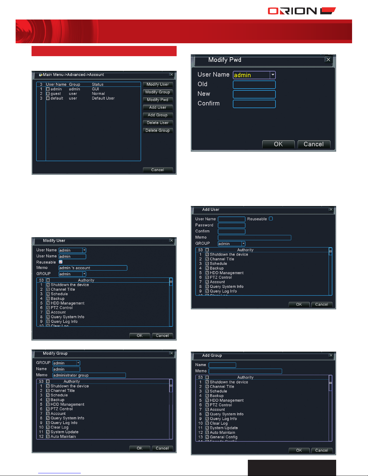
30 adVanced > account
Account menu allows the management of user accounts and
level of authority.
› INDEX: Number allocated to a user name.
› USER NAME: There is no limit to the number of user
accounts. Admin user account has full access to all DVR
functionality. All user names must be unique. Admin account
cannot be deleted.
› GROUP: Group of user accounts. Each user account can only
belong to one group.
› STATUS: User account status.
› MODIFY USER: Modify the existing user attribute.
› MODIFY GROUP: Modify the existing group attribute.
› MODIFY PWD: Modify the password for existing user account.
› ADD USER: Add a new user account. Check Reuseable to
allow multiple login using this user account at the same time.
Enter a suitable username and password. Select the group
the user account belongs to. Authority list contains all the
functionality of the DVR. Check the functions to allow user
access to the functions. Memo is for additional information
regarding the user account. It is recommended that user or
guest accounts have lower level of authority than admin.
› ADD GROUP: Add a new group. Creating a group makes
it convenient when assigning level of authority to user
accounts. User accounts can be assigned to a group to share
the same level of authority. Enter a suitable group name
and define the level of authority for the group. Memo is for
additional information regarding the group.
Page 22

PROFESSIONAL
SuRvEILLANcE SYSTEM
22
four channel digital video recorder SC144
31 adVanced > online user
Online user allows the monitoring users logged into the
DVR through the network.
› USER NAME: User name of account logged in to DVR
through the network.
› IP: IP address of the external device.
› LOGIN TYPE: Level of authority of User account.
› DISCONNECT: Online users can be forced to disconnect
from the DVR by selecting user from list and selecting
Disconnect.
› DELETE USER: Select the user accounts on the list and press
Delete User to delete users.
› DELETE GROUP: Select group name from the list. Select
Delete Group to delete group. Groups that contain users
cannot be deleted.
32 adVanced > outPut adjust
Output adjust menu allows the calibration of the display output
on the monitor.
› TOP DEFLATE: Compress display output from top.
› BOTTOM DEFLATE: Compress display output from bottom.
› LEFT DEFLATE: Compress display output from left.
› RIGHT DEFLATE: Compress display output from right.
› HORIZONTAL BLACK: Shift horizontal position of video in
channel box.
› VERTICAL BLACK: Shift vertical position of video in
channel box.
33 adVanced > auto maintain
Auto Maintain allows the DVR to automatically maintain the
recording operation.
› AUTO-REBOOT SYSTEM: Automatically reboot at a certain
time of the week. Select a suitable time when events are
least likely to occur. Rebooting periodically is recommended
to maintain the reliability of the DVR.
› AUTO-DELETE OLD FILES: Automatically delete older
recording files. Select Never to disable auto-delete. Select
Custom and enter the numbers of days ago in the box to
delete files from the specified number of days ago.
Page 23

PROFESSIONAL
SuRvEILLANcE SYSTEM
23
four channel digital video recorder SC144
34 adVanced > restore
Restore allows restoration of DVR factory default settings.
Performing this will remove user settings.
RESTORING FACTORY DEFAULT SETTINGS
a Select specific or all DVR functions.
b Select OK to confirm restoring function parameters to
default factory settings.
35 adVanced > uPgrade
Upgrade allows DVR to be upgraded from external flash drive.
As we are constantly upgrading the firmware to make the
DVR more user friendly and reliable, firmware updates may be
required.
UPGRADING DVR FIRMWARE
a Firmware update is only necessary when instructed. The
latest firmware is available on Orion website for download.
b Copy it to your flash drive and plug it onto the DVR. Make
sure there are no other files to make sure DVR detects the
upgrade files.
c Select the drive that contains the firmware in Upgrade
Position.
d Select the firmware file in Upgrade File.
e Select Upgrade to commence upgrade.
36 adVanced > deVice inFo
Device Info displays the device basic information.
› AUDIO IN CHANNELS: Number of audio input channels.
› ALARM IN CHANNELS: Number of alarm input.
› ALARM OUT CHANNELS: Number of alarm output.
› GUI THEME: Graphic interface theme.
› REMOTE CONTROL TYPE: Types of remote control
compatible with DVR.
› MAXIMUM PLAYBACK LARGE: Maximum number of
channels in playback.
› DEFAULT PLAYBACK LARGE: Default number of channels
in playback.
› ENABLE RS232: Enable RS232 serial port.
› ENABLE PTZ: Enable RS485 port fot PTZ devices.
Page 24

PROFESSIONAL
SuRvEILLANcE SYSTEM
24
four channel digital video recorder SC144
37 adVanced > imPort/exPort
Import/Export menu allows the exportation of current DVR
settings into external storage device or importation of DVR
settings from external storage device into DVR. Local DVR log
can also be exported to external storage device.
EXPORTING DVR SETTINGS
a Plug in external storage device onto DVR.
b Select storage device from Device Name list.
c Click on Export under Set category to export DVR settings to
storage device.
IMPORTING DVR SETTINGS
a Plug in external storage device that contains DVR settings
file onto DVR.
b Select storage device from Device Name list.
c Select correct DVR file in File Name list under Set category.
d Click on Import under Set Category to import DVR settings
from file to DVR.
EXPORTING LOG
a Plug in external storage device onto DVR.
b Select storage device from Device Name list.
c Click on Export under Log category to export DVR log to
storage device.
38 inFo > Hdd inFo
HDD info displays information of the internal hard drives.
› TYPE: Hard drive operating mode.
> READ: Reading hard drive is allowed. Writing to the hard
drive is restricted.
> READ/WRITE: Reading and writing to hard drive are
allowed.
> REDUNDANT: Backup recording files are stored in this
hard drive.
> FREE: Hard drive is not in use.
> IN USE: DVR currently recording into the hard drive.
› CAPACITY: Maximum hard drive storage space.
› CAPACITY LEFT: Remainder hard drive storage space.
› STATUS: Status of the hard drive.
> NORMAL: Hard drive is operating normally.
> ERROR: Hard drive is faulty.
> FREE: Hard drive is not in use.
> IN USE: DVR currently recording into the hard drive.
Page 25

PROFESSIONAL
SuRvEILLANcE SYSTEM
25
four channel digital video recorder SC144
39 inFo > BPs
BPS displays the data transmission rate of video encoding streams.
CALCULATING DAYS OF CONTINUOUS RECORDING
Average BPS(MB/H) at high setting is around 500 MB/H
Number of days
= Hard Disk Space/((MB/H) x Number of Channels x 24 Hours)
= 500000/(500 x 4 x 24)
= 10 Days
40 inFo > log
Log allows monitoring of all events that occur on the DVR.
SEARCHING EVENT LOG
a Select the type of events to search for. Select from the
following type of events.
> All > System
> Config > Storage
> Alarm Event > Week Day
> Account > Playback
b Select the start date and time.
c Select the end date and time.
d Select Search to search for all events that matches the criteria
within the time span. A list shows the event logs in detail.
> INDEX: Number allocated to event.
> LOG TIME: Time of event occurence.
> TYPE: Type of event.
> LOG: Event description.
e Select Remove to clear all log entries.
41 inFo > Version
Version displays the system version, build date and serial
number. This information serves as a reference when tracking
any known issues with a particular version of DVR as well as
making sure the firmware version is up-to-date.
42 logout
› LOGOUT: Log out current user.
› SHUT DOWN: Turn off DVR power.
› REBOOT: Restart DVR.
Page 26

PROFESSIONAL
SuRvEILLANcE SYSTEM
26
four channel digital video recorder SC144
43 cms introduction
Orion Central Management Software is a powerful program
that allows remote monitoring and management of DVR in a
distributed network.
THIS SOFTWARE ALLOWS USERS TO:
› Monitor video feeds from DVR in real-time.
› Backup recordings from DVR to PC.
› Create a local recording plan for PC.
› Calibrate the settings of the DVR.
› Manage and monitor multiple DVRs.
INSTALLING THE SOFTWARE
a Insert the disk.
b Double click the setup file CMS.exe to commence setup wizard.
c Follow all the wizard prompts to complete setup.
d Start using software.
MINIMUM PC REQUIREMENTS
› CPU: Pentium 4 above 2.0 GHz.
› Memory: More than 512MB.
› Graphics Card: Dedicated graphics card required.
› OS: Windows 2000/ Windows XP / Windows 2003/
Windows Vista.
› DirectX: DirectX 9.0c or above.
› Internet Connection: 512kbps and above.
44 cms login
Username and password is required to login into Orion CMS.
The default username is “admin” and no password. Select Save
to remember the username and password.
It is highly recommended that a strong password is created as
soon as possible to protect your privacy.
45 cms main interFace
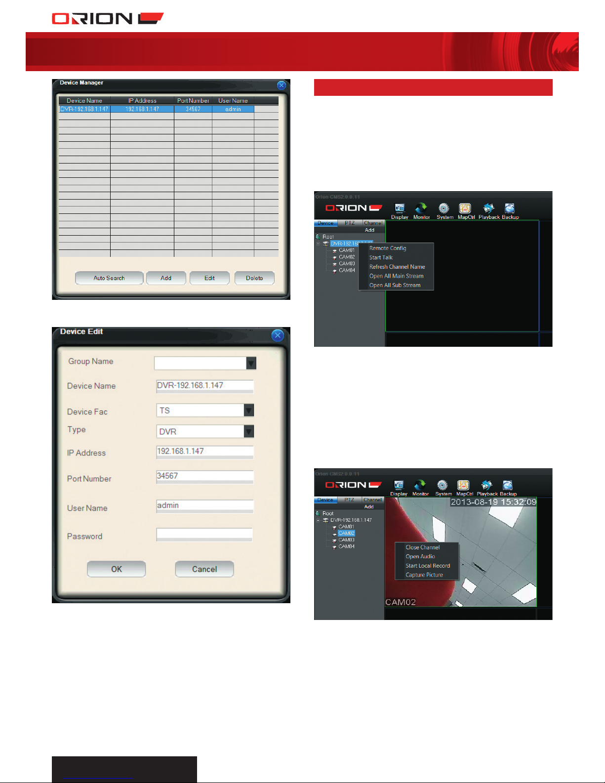
46 cms add dVr
MANUALLY ADDING DVR
a Select Add under Device List tab and select Add Device.
b Select Add in Device Manager menu.
a db c e f g h i l
j
l
k
a Device List g Map Control
b PTZ Control h Playback
c
Color/Channel Control i Backup
d
Screen Division j Main Monitoring Display
e
Monitor Project k Log
f
System Settings l Current User
Page 27

PROFESSIONAL
SuRvEILLANcE SYSTEM
27
four channel digital video recorder SC144
c Enter the DVR information in the form.
> DEVICE NAME: Enter suitable DVR name
> DEVICE FAC: Select TS.
> TYPE: Select DVR.
> IP ADDRESS: Enter DVR IP address or domain name.
For local access, refer to DVR Main Menu > System >
Network to acquire local IP address.
For remote access, refer to DVR Main Menu > System > Net
Service > DDNS to acquire domain name.
> PORT NUMBER: Enter DVR media port. Default is 34567.
Refer to DVR Main Menu > System > Network to acquire
port number.
> USER NAME: Enter DVR account name.
> PASSWORD: Enter DVR account password.
d Select OK to complete form and exit to main interface. The
newly added device will appear on the Device List.
e Double click on the new device to connect to DVR and
expand the list of cameras.
f Double click any of the camera channels to start live
monitoring.
AUTOSEARCH DVR
a DVR and PC must be connected to the same router/modem
when using Autosearch function.
b Select Add under Device List tab and select Add Device.
c Select Auto Search to bring up the following menu.
d Auto search will automatically search for DVR in same
network. Select DVR and press Add to add DVR to include it
into Device List. Select Refresh to search for connected DVR.
e Select DVR in Device Management menu and select Edit.
Page 28
PROFESSIONAL
SuRvEILLANcE SYSTEM
28
four channel digital video recorder SC144
f Edit the DVR details such as Device Name, Device Fac, Type,
User Name and Password.
g Select OK to complete form and exit to main interface.
The newly added device will appear on the Device List.
47 cms liVe monitoring
COMMENCING LIVE MONITORING
a Select Device tab the top left section of main interface.
b Double click on the DVR on the Device List to connect to DVR.
c Right click DVR on list to drop down menu.
d Select Open All Main Stream to open all DVR channels on
main monitoring display in high quality stream.
Select Open All Sub Stream to open all DVR channels on
main monitoring display in lower quality stream.
Right click DVR name to drop down extended menu.
› REMOTE CONFIG: Configure DVR settings from Orion
CMS. The interface is identical to that of the DVR.
› START TALK: Commence sending audio communication
from PC to DVR.
› REFRESH CHANNEL NAME: Refresh DVR channel titles.
› OPEN ALL MAIN STREAM: Open all DVR channels on main
monitoring display in high quality stream.
› OPEN ALL SUB STREAM: Open all DVR channels on main
monitoring display in lower quality stream.
Right click channel to drop down extended menu.
› CLOSE CHANNEL: Close channel video.
› OPEN AUDIO: Commence audio listening from DVR
channel. This corresponds to the audio input on the rear
panel of DVR.
› START LOCAL RECORD: Commence recording channel
on PC storage device. The directory is determined in Local
Settings. Refer to 53 CMS System > Local Settings for details.
› CAPTURE PICTURE: Take snapshot of channel and store on PC
storage device. The directory is determined in Local Settings.
Refer to 53 CMS System > Local Settings for details.
Page 29

PROFESSIONAL
SuRvEILLANcE SYSTEM
29
four channel digital video recorder SC144
48 cms cHannel control
Channel control allows the control of channel video and audio
monitoring as well as adjustment of channel colour settings.
Select a channel and open Channel Control Tab.
› RECORD: Commence recording channel on PC storage
device. The directory is determined in Local Settings. Refer
to 53 CMS System > Local Settings for details.
› CAPTURE: Take photo snapshot of channel and store on PC
storage device. The directory is determined in Local Settings.
Refer to 53 CMS System > Local Settings for details.
› TALK: Commence sending audio communication from
PC to DVR.
› LISTEN: Commence audio listening from DVR channel.
This corresponds to the audio input on the rear panel of DVR.
› VOLUME: Audio listening volume adjustment.
› BRIGHTNESS: Channel brightness adjustment.
› CONTRAST: Channel contrast adjustment.
› SATURATION: Channel saturation adjustment.
› HUE: Channel hue adjustment.
49 cms PtZ control
PTZ control allows the control of PTZ devices connected to
the DVR.
› DIRECTIONAL ARROWS: Control of the PTZ camera in 8
different directions.
› SPEED: Movement speed of PTZ camera.
› ZOOM: Select +/- button to adjust PTZ camera zoom.
› FOCUS: Select +/- button to adjust PTZ camera focus.
› IRIS: Select +/- button to adjust PTZ camera aperture.
› PRESET: Preset number assigned to camera position. Refer
to 23 PTZ Control-Preset > Creating Preset for details.
> MOVETO: Select preset number and select MoveTo to
move PTZ camera to preset position.
> SET: Store current PTZ camera position to preset number.
› PATROL: Patrol number assigned to list of presets. Refer to
24 PTZ Control-Patrol > Creating Patrol for details.
> START: Select patrol number and select Start to
commence PTZ camera patrol sequence.
> SET: Configure patrol sequence.
› SCAN: Refer to 26 PTZ Control-Border > Creating Border
for details.
> FUNC SET: Configure Auto Scan settings.
> SCAN: Enter number in box and select Scan to
commence camera border scanning movement.
› PATTERN: Enter pattern number and select Pattern to
commence camera pattern movement. Refer to 25 PTZ
Control-Pattern > Creating Pattern for details.
› AUXILIARY: Enter required auxiliary function number and
select AuxOpen or AuxClose to enable or disable function.
Refer to PTZ Control for details.
Page 30

PROFESSIONAL
SuRvEILLANcE SYSTEM
30
four channel digital video recorder SC144
50 cms disPlay
Display menu allows the configuration of different live monitoring
view modes.
CONFIGURING SCREEN DISPLAY MODE
a Select
Display on the top toolbar.
b Select the preferred view mode.
c Select Full screen to enlarge main monitoring display to full
screen. Press Esc button to exit full screen mode.
51 cms monitor
Monitor menu allows the creation of surveillance plans for every
DVR and its channels. Monitor Task defines what DVR channels
to be displayed on the Monitoring Display. Monitor Project
defines when the monitoring tasks are enabled.
CREATING MONITORING TASK
a Select
Monitor on the top toolbar.
b Select Config to bring up the following menu.
c Select New to create new monitoring task.
d Enter a suitable name for the monitoring task, select the
number of windows to be displayed and select the video
stream type.
e Drag and drop channel from Device List to the monitoring task
table to include channel in the monitoring task. The channels
will be automatically assigned to the windows.
f Select created window to configure window in more detail.
Drag and drop more channels to the window table to enable
window to continuously switch from one channel to another
according to the list.
StayTime determines the duration the channel is displayed on
the window before switching to the next channel.
f Select OK to confirm creation of monitoring task.
DRAG
AND
DROP
DRAG
AND
DROP
Page 31

PROFESSIONAL
SuRvEILLANcE SYSTEM
31
four channel digital video recorder SC144
ENABLING MONITORING TASK
a Select
Monitor on the top toolbar. The created
monitoring task will appear on the menu.
b Select created monitoring task to start monitoring according
to task.
CREATING MONITORING PROJECT
a Create monitoring task.
b Select
Monitor on the top toolbar and select Monitor
Project tab.
c Select New to create new Monitor Project.
d Enter a suitable name for the monitoring project, select
monitoring task to be displayed and enter required start time.
e Select Add to add Monitoring Task to the project. Other
monitoring tasks can be added to the project to view different
tasks at different times.
ENABLING MONITORING PROJECT
a Select
Monitor on the top toolbar. The created
monitoring project will appear on the menu.
b Select created monitoring project to start monitoring
according to project.
52 cms system > user manager
User Manager allows the management of group and user
accounts for Orion CMS. Access User Manager by clicking on
System and selecting User Manager.
Page 32

PROFESSIONAL
SuRvEILLANcE SYSTEM
32
four channel digital video recorder SC144
ADDING NEW GROUP
a Right click Group on the left tab and select Add Group.
b Enter suitable group name and brief decription of group.
c Select Authority to grant authority for the group to access
selected CMS functionality.
d Select Device to grant authority for the group to access
selected device.
e Select OK to confirm creation of new group.
MODIFYING GROUP
a Double click on group name to modify group attribute.
b Group Normal displays the list of users in the group.
c Select Modify and select User Accounts to add or remove
user accounts from the group.
d Select Apply to confirm or select Cancel to dismiss
modifications.
e Group Device displays the list of DVRs added to CMS.
f Select Modify and select DVRs to allow or disallow group
members access to those DVRs.
g Select Apply to confirm or select Cancel to dismiss
modifications.
h Group Authority displays the list of authorities of the
group members. This defines the level of access the group
members have to the CMS functionality.
Page 33

PROFESSIONAL
SuRvEILLANcE SYSTEM
33
four channel digital video recorder SC144
i Select Modify and select authority to allow or disallow group
members access to those functionalities.
j Select Apply to confirm or select Cancel to dismiss
modifications.
ADDING NEW USER
a Right click User on the left tab and select Add User.
b Select group for new user. User level of authority is defined
by the group.
c Enter suitable User Name and Password.
e Select OK to confirm creation of new user.
53 cms system > local setting
Local Setting allows the configuration of settings on local PC.
Access Local Setting by clicking on
System Settings and
selecting Local Setting.
› RECORD PATH: Directory of backup video recording files.
› RECORD FORMAT: File title format of recording files.
› PICTURE PATH: Directory of backup picture files.
› PICTURE FORMAT: File title format of picture files.
› ALARM PIC PATH: Directory of backup alarm triggered
picture files.
› PACKET TYPE: Type of video recordings.
> PACKET SIZE: Recording files segmented according to
file size. Select packet file size in Mb size.
> PACKET TIME: Recording files segmented according to
file time duration. Select packet file size in minute duration.
› AUTORUN WHEN PC BOOTS: Automatically open CMS at
startup.
› START WITH LAST STATE: Open CMS according to the
state when it was last closed.
› AUTO LOGIN: Automatically login to CMS.
Page 34

PROFESSIONAL
SuRvEILLANcE SYSTEM
34
four channel digital video recorder SC144
54 cms system > alarm setting
Alarm Setting allows the configuration of alarm triggered
recording and notification. Access Alarm Setting by clicking on
System and selecting Alarm Setting.
› ALARM TYPE: Type of alarm trigger.
> SENSOR: Alarm triggered by DVR wired sensor input. Not
applicable for this model.
> MOTION: Alarm triggered by detection of motion.
> VIDEO LOSS: Alarm triggered by detection of video
signal loss.
> SHELTER: Alarm triggered by detection of camera view
being obscured.
> DISK ERROR: Alarm triggered by detection of error when
reading or writing to hard drive.
> DISK FULL: Alarm triggered by detection of insufficient
hard drive space.
> DISCONNECT: Alarm triggered by detection of DVR
disconnection.
› ALARM ENABLE: Enable or disable alarm.
› ALARM PROMPT SOUND: Enable or disable sound output
when alarm triggered.
› SOUND PATH: Sound file to play when alarm triggered.
› AUTO WATCH WARN: Automatically display video channel
on monitoring screen when alarm triggered.
› LINK: Link video channel to Motion alarm or Sensor alarm.
Select Alarm Port and corresponding Video Channel then
select Add to link them.
55 cms maP control
Map control allows camera location to be associated with the
premises layout plan. Select Map Control to access map
control menu.
CREATING A MAP
a Select Edit to enable editing of map.
b Select Picture Edit to open Background Picture Manager.
c Select Add and Browse for picture of premises layout plan.
Enter a suitable name and description of the picture.
› IGNORED TIME: Multiple consecutive alarm trigger within
this duration will be disregarded.
› LINK CAPTURE: Snapshot of channel stored on local PC
when alarm triggered.
› CAPTURE DELAY TIME: Duration between alarm trigger
and snapshot taken.
Page 35

PROFESSIONAL
SuRvEILLANcE SYSTEM
35
four channel digital video recorder SC144
d Select OK to confirm adding picture.
e Select Picture on the bottom toolbar of Map control menu.
Drag and drop the added picture name from picture list to the
top left box. This mini map allows users to scroll the image.
f Select Device on the bottom tool bar. Drag and drop DVR
video channels to the premises layout picture. Position the
video channel icon according to the location of the camera
on the premises.
g Complete creation of map by selecting Save and
uncheck Edit.
h Double click on
Video Channel Icon on the map to
connect to camera and display video on Main Monitoring
Display. The video channel icon flickers when alarm is
triggered.
56 cms PlayBack
Playback allows the review of recorded videos in local PC or
DVR as well as downloading files from the DVR. Select
Playback to access playback menu.
PLAYBACK RECORDED VIDEOS
a DEVICE: Select DVR to review.
b CHANNEL: Select DVR camera channel.
c TYPE: Select type of recording to search for.
> NORMAL: Normal recordings recorded within the
scheduled periods without events.
> ALARM: Recordings triggered by alarm input.
> MOTION: Recordings triggered by motion detect function.
> MANUAL: Continuous recordings.
d DATE AND TIME: Enter date and enter time or select DVR
scheduled periods.
e SOURCE: Select source of recording, Local PC or DVR
f SEARCH: Search for record files based on search criterias.
g PLAY: Select record files from Record List and select Play to
commence playing recording.
h DOWNLOADS: Select record files from Record List and
select Download to store selected files onto local PC.
i BULK LOAD: Select DVR and channel. Select Bulk Load to
download all recording files from DVR channel.
j RECORD LIST: Displays the recordings based on search
criteria.
k NAVIGATION BAR: Displays playback progress of current
recording. Click any point of the timeline to skip to desired
time.
l PLAYBACK CONTROL:
Pause Previous Frame
Play Next Frame
Stop Next File
Fast Forward Open File
Slow Fullscreen
Record Mute/Volume
Snapshot
m DOWNLOADS: Displays all the current downloads from DVR
to local PC.
DRAG
AND
DROP
DRAG
AND
DROP
a
b
d
e
f
j
l
m
k
g
h
i
c
Page 36

PROFESSIONAL
SuRvEILLANcE SYSTEM
36
four channel digital video recorder SC144
57 cms BackuP conFig
Backup Config allows the scheduling of video recording backup
on local PC. Access Backup Config by clicking on Backup
and selecting Backup Config.
BACKING UP VIDEOS FROM DVR ON PC
a PACKET TIME: Select preferred backup file duration.
b AUTO RECOVER: Select to automatically resume backup.
c ALARM PACK TIME: Enter preferred duration of recording
triggered by alarm.
d DEVICE LIST: Displays all the added DVRs and their video
and alarm channels.
e CHANNEL LIST: Drag and drop video channels from Device
list to Channel List to backup on local PC.
f DISK LIST: Displays all the available storage devices linked
to the local PC. Select to designate the location of backup
files.
g SCHEDULE: Displays the backup schedule for everyday of
the week. The green bar indicates that backup is scheduled
during those times and white bar indicates that no backup is
scheduled during those times.
h SETUP: Select Setup to configure the backup schedule
for a particular day. There are up to 6 periods for each day
that can vary in time and recording trigger. In the following
example, the CMS is set to backup normal and motion
triggered recording files between 8am to 5pm.
i After creating a backup schedule, exit Backup Config
menu and select Start Backup on the top toolbar to
commence backup.
58 cms log
Log allows monitoring of all events that occur on the DVR and CMS.
SEARCHING EVENT LOG
a Select Event Display tab at the bottom of the main interface.
b Select Alarm Log tab to view alarm events on DVR. Select
Search Log to search for Alarm Log in more detail.
c Select Operate Log tab to view all operation events on CMS.
DRAG
AND
DROP
Page 37

PROFESSIONAL
SuRvEILLANcE SYSTEM
37
four channel digital video recorder SC144
59 moBile aPPlication
Mobile application allows users to access the DVR remotely on
their mobile devices such as smartphone and tablets.
MOBILE APPLICATIONS
vMEyeV2 is available for Apple devices from App Store.
vMEye+ is available for Android devices from Google Play
MAIN INTERFACE
a
Display Window
b Channel Select
c
PTZ Control
d
Channel Page Switch
e
Play Live Preview
f
Snapshot
g
Device List
h
App Information
c Select Add in Device List menu.
b Select Device List on the bottom toolbar.
ADDING DVR TO MOBILE APP
a Select Address Mode to enter Main Interface.
A
B
C
D
d Enter DVR information and select Save to complete
DVR entry.
b
e f g h
d
c
a
Page 38
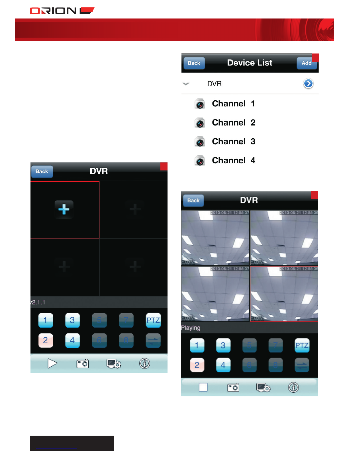
PROFESSIONAL
SuRvEILLANcE SYSTEM
38
four channel digital video recorder SC144
E
G
F
> NAME: Enter suitable DVR name.
> ADDRESS: Enter DVR IP address or domain name.
For local access, refer to DVR Main Menu > System >
Network to acquire local IP address.
For remote access, refer to DVR Main Menu > System >
Net Service > DDNS to acquire domain name.
> PORT: Enter DVR Mobile Port. Default is 34599. Refer to
DVR Main Menu > System > Net Service > Mobile Monitor
to acquire port number.
> USER ID: Enter DVR account name.
> PASSWORD: Enter DVR account password.
> MAX CHANNEL: Enter number of video input channels.
This DVR has 4 channels.
f Select DVR and channel to start live monitoring.
e Return to Main Interface and select + button to add DVR.
g Repeat steps e to f on other display windows to view up to
4 channels simultaneously on Main Interface.
Page 39

PROFESSIONAL
SuRvEILLANcE SYSTEM
39
four channel digital video recorder SC144
60 trouBlesHooting guide
PROBLEM POSSIBLE CAUSE SUGGESTED REMEDY
DVR/camera has
no power or not
powering up
Power supply is loose or unplugged.
No power at socket outlet/power point.
Check all cable and power supply connections.
Check power at socket outlet/power point.
Hard drive is not
detected by DVR
Hard drive not formatted.
Hard drive power/SATA cable is loose.
Format hard drive. Refer to 29 Advanced > HDD Manage for details.
Check hard drive power/SATA cable connection.
No picture
Camera cable is loose or not connected. Check both ends of cable, DVR and camera.
Camera has no power.
No power at socket outlet/power point.
Check all cable and power supply connections.
Check power at socket outlet/power point.
TV/monitor display settings.
Video display can only be made via VGA connection. Check the
VGA cable connections at both ends and ensure connections are secure.
Check the TV/monitor is powered up and on the right channel.
Change the VGA cable if necessary.
Change the DVR display format to PAL or NTSC. Refer to 16 System
> General for details.
Connect DVR to another TV/monitor display.
Electronic interference.
Relocate camera and DVR away from sun, rain, radio transmitting devices,
heat sources, metal objects or major obstacles.
Frozen white screen
- Disconnect power to DVR and then reconnect.
When IR night vision
is activated, screen
only displays white
Infra-red LED light is reflected off from
glass or reflective objects.
Relocate camera away from windows, reflective and glass objects
or remove obstacles.
When IR night vision
is activated, screen
only displays black
and white
Infra-red LED light is activated. This is normal. No action required.
DVR does not
record according to
schedule or motion
detect settings
DVR is not set up correctly.
Hard drive is missing or full.
Check DVR date and time, schedule setting and motion detect setting.
Check hard drive setting.
Hard drive
memory full
Overwrite is not enabled. Enable hard drive overwrite, format hard drive or install new hard drive.
Recorded videos
does not have sound
Microphone is not installed.
Mute is on.
Microphone is not included in the system. It needs to be installed separately.
Turn off mute.
Note: Audio recording is prohibited or illegal in some states or require
consent from both parties. Please consult your local legal advisers before
audio recording.
Poor image quality
Signal interference.
Camera channel resolution setting.
Signal interference.
Strong radio emitting or transmitting
devices nearby.
Strong electromagnetic interference
nearby.
Relocate camera and DVR away from sun, rain, radio transmitting
devices, heat sources, metal objects or major obstacles.
Change camera channel resolution setting.
Refer to 9 Record > Record Conf for details.
Audio interference
Microphone too close to
another audio object.
Relocate microphone (Microphone not included).
Page 40

PROFESSIONAL
SuRvEILLANcE SYSTEM
40
four channel digital video recorder SC144
61 digital Video recorder 62 camera
›VIDEO
Video Format PAL or NTSC
Video Input 4 Composite BNC Inputs
(1.0Vp-p, 75Ω)
2 Composite BNC Outputs
Video Output (1.0Vp-p, 75Ω)
VGA (1024 x 768)
Display Resolution 1024 x 768, 800 x 600
Display Frame Rate PAL 25 fps per channel
NTSC 30 fps per channel
›AUDIO
Audio Input 1 RCA Input
Audio Output 1 RCA Output
›RECORDING
Compression Format H.264
Recording Resolution PAL - D1 (704 x 576)
- HD1 (704 x 288)
- CIF (352 x 288)
NTSC - D1 (704 x 480)
- HD1 (704 x 240)
- CIF (352 x 240)
Recording Frame Rate PAL 25 fps per channel
NTSC 30 fps per channel
Recording Mode Manual / Motion / Schedule
Hard Drive Support 1 SATA HDD
(500GB HDD installed)
›NETWORK
LAN Connection Yes
Network Interface RJ45 10M/100M
Ethernet Connector
Network Protocol TCP/IP, DDNS, UPnP, PPPOE,
DNS, DHCP, FTP, SMTP, NTP
Remote Operation Yes
›GENERAL
Power Supply DC 12V 2A
Operating Temperature 0°C ~ 50°C
Operating Humidity 10% ~ 90%
Backup Method USB to Flash Drive/Network
Serial Port RS485 for PTZ Camera
USB 2 x USB 2.0
Mouse Yes
Remote Control Yes
›VIDEO
Sensor 6mm Colour CMOS Sensor
Horizontal Resolution 600TVL
Image Resolution PAL: 648 x 488
NTSC: 648 x 488
Lens F: 3.6mm
Electronic Shutter PAL: 1/50 ~1/100000
NTSC: 1/50 ~ 1/100000
Min Illumination 0 Lux (IR on)
Gain Control Auto
White Balance Auto
Backlight Compensation Auto
Gamma Correction 0.45
Signal/Noise Ratio >48dB
› NIGHT VISION
Infrared Light 24 IR LEDs
Range Up to 20m
IR Cut Filter Yes
›GENERAL
Power Supply DC 12V 500mA
Indoor/Outdoor Indoor and Outdoor
IP Rating IP66
Dimensions 160(L) x 60(W) x 60mm(H)
Weight 250g
Operate Temperature -5° ~ 50°C
Operating Humidity 10% ~ 85%
Page 41

PROFESSIONAL
SURVEILLANCE SYSTEM
Arlec Australia Pty. Ltd. ACN 009 322 105 (“Arlec”) gives the Warranty.
Arlec’s telephone number, address and email address are:
Customer Service: (03) 9982 5111
Building 3, 31 – 41 Joseph Street, Blackburn North, Victoria, 3130
Blackburn North LPO, P.O. Box 1065, Blackburn North, 3130
Email: custservice@arlec.com.au
CPIN002659
63 warranty
Arlec guarantees this product in accordance with the Australian
Consumer Law.
Arlec also warrants to the original first purchaser of this product
(“you”) from a retailer that this product will be free of defects
in materials and workmanship for a period of 12 months from
the date of purchase; provided the product is not used other
than for the purpose, or in a manner not within the scope of the
recommendations and limitations, specified by Arlec, is new and
not damaged at the time of purchase, has not been subjected
to abuse, misuse, neglect or damage, has not been modified or
repaired without the approval of Arlec and has not been used for
commercial purposes (“Warranty”).
If you wish to claim on the Warranty, you must, at your own expense,
return the product, and provide proof of original purchase and your
name, address and telephone number, to Arlec at the address
below or the retailer from whom you originally purchased the
product within 12 months from the date of purchase.
Arlec will (or authorise the retailer to) assess any claim you may make
on the Warranty in the above manner and if, in Arlec’s reasonable
opinion, the Warranty applies, Arlec will at its own option and
expense (or authorise the retailer to) replace the product with the
same or similar product or repair the product and return it to you
or refund the price you paid for the product. Arlec will bear its
own expenses of doing those things, and you must bear any other
expenses of claiming on the Warranty.
The Warranty is in addition to other rights and remedies you
may have under a law in relation to the product to which the
Warranty relates.
Our goods come with guarantees that cannot be excluded
under the Australian Consumer Law. You are entitled to a
replacement or refund for a major failure and for compensation
for any other reasonably foreseeable loss or damage. You are also
entitled to have the goods repaired or replaced if the goods fail
to be of acceptable quality and the failure does not amount to a
major failure.
 Loading...