

Page 1
Installation & User’s Guide
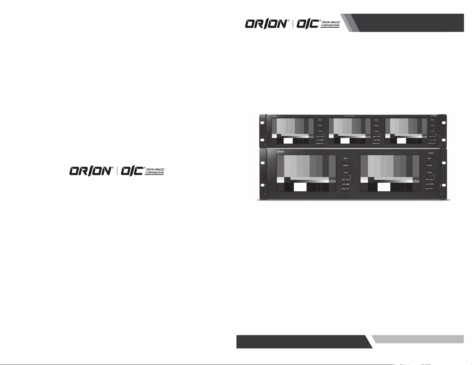
HIGH PERFORMANCE BROADCAST RACK MOUNT MONITOR
ver. 1-1-6182012
OIC-7002 / OIC-5003
http://www.orionimages.com
All contents of this document may change without prior notice, and actual product appearance may differ from that depicted herein
Page 2
Installation and User’s Guide
All contents of this document may change without prior notice, and actual product appearance may
differ from that depicted herein.
1. Safety Instruction
Follow this safety instruction to use the monitor properly and prevent the damages. Keep this user’s
guide book for later use.
Warning
Cautions
If the user does not follow this instruction, it may cause the serious
damage to the user.
If the user does not follow this instruction, it may cause the slight
damage to the user or cause some damages to the monitor.
Warning
Never remove the back over and touch the inside of the monitor. If you need a service, please
contact the service center.
Keep away the monitor from the direct sunlight and a heating appliance.
Never push objects of any kind into this product as they may result in a risk of fire or electric
shock.
Connect the power code to the wall outlet tightly. If the power code or plug is defective and the
wall outlet is not tight, please do not use them.
Do not install this monitor on the outside and near water. If may cause damage to the product,
electric shock and fire.
For cleaning do not use liquid cleaners. Never touch the power plug with wet-hands.
When lightning and thundering, unplug the monitor from the wall outlet and never touch it.
Unplug this product from the wall outlet, when it does not operate for a long time.
When smoking and noising from the monitor, unplug the product from the wall outlet and
contact a service center.
Installation and User’s Guide
2
19
Page 3
Installation and User’s Guide
Installation and User’s Guide
Cautions
Install this monitor some distance from the wall and do not install unless Proper ventilation is
provided.
Place this product on a stable place. If not, it may fall, causing serious Damages to the monitor
and people.
The openings must not be blocked by curtain, rug or other sim ilar surface.
When carrying this monitor, be careful not to damage the panel and drop it. It may cause some
trouble.
Before carrying the monitor, turn it off and unplug the signal cables and the power code from
the wall outlet.
Take the power plug out from the wall outlet. Do not pull the cable. It may snap the inner wires
and cause overheating and fire.
Install this monitor about 50cm far from the eyes and an angle of 0~15 degrees below eyes.
Too close installation may cause having weak sight.
Do not press the LCD panel with hands or the sharpened material hard.
For cleaning, unplug the monitor from the Wall outlet. Do n ot use the liquid cloth. Use the soft
cloth.
Do not use the chemical liquid for cleaning. It may cause fading and breakage.
18
3
Page 4

Installation and User’s Guide
TABLE OF CONTENTS
1. Safety Instruction ......... ................. ........ ................. ..... 2
2. Installation ......... ................. .................................... 5
2.1. Parts List ............................................................. 5
2.2. How to Install ......................................................... 6
2.3. Function and Control Key ............................................... 8
3. OSD MENU ................................... ................. ......... 11
4. Features .............................................. ................. 13
5. Mechanical Drawing .......... ................. ........ ................. 14
5.1. Dimension[Units :mm] for OIC-7002 .................................... 14
5.2. Dimension[Units :mm] for OIC-5003 .................................... 15
6. 2 Year Limited Warranty ................................................. 16
7. Troubleshooting ........................................................ 17
Installation and User’s Guide
7.
Troubleshooting
When the following troubles are occurred, follow the trouble shooting before contacting a service
center.
The screen doesn’t show up
Make sure if the power supply is connected property
Turn on the power.
Select the input signal right for the connected port.
The screen is too light or to dark
Control the BRIGHTNESS
4
17
Page 5

Installation and User’s Guide
Installation and User’s Guide
6. 2 Year Limited Warranty
ORION Images Corporation. carries a limited warranty from ship date against defects in materials
and workmanship. ORION Images Corporation. is not liable for improper installation that results in
damage to mounts, adapters, display equipment or personal injury.
Contact ORION Images Corporation.
In the event of missing and/or damage equipment, or technical questions, the following information
can help in the completion of the installation.
Address: 7300 Bolsa Avenue, Westminster CA 92683
Tel: (714)766-6300 / Fax: (714)766-6310
Email: rma@orionimages.com
Website: http://www.orionimages.com
2. Installation
2.1. Parts List
LCD Monitor (1SET), Power Cable (1EA), AC/DC Adaptor (1EA), User Manual (1EA).
MONITOR
Power AC/DC Adaptor User Manual
16
5
Page 6

Installation and User’s Guide
○
1
○
2
○
3
○
4
○
5
2.2. How to Install
First, make sure that the front power button is turned off.
If you press button, button is locked and power will be turned on. And then press again the button,
button is released and power will be turned off.
2.2.1. SDI Connection
Turn off the power button.
Connect the required cables for video signal input and output.
Connect the AC power cord’s connector to the AC power connector on the AC/DC adaptor.
Connect the 4-pin female XLR connector of adaptor to the back of monitor.
Insert AC power cord’s plug to an AC outlet (100-240V @ 50/60 Hz).
Turn on the power button.
Installation and User’s Guide
5.2. Dimension[Units :mm] for OIC-5003
Holes for Rack mount
XLR Connector: 4PIN XLR Connector, 12VDC
1
2
SDI IN: BNC (75Ω Terminated), SMPTE-424M, SMPTE-292, SMPTE-259M.
SDI OUT: BNC (75Ω Terminated), SMPTE-424M, SMPTE-292, SMPTE-259M.
3
GPI: D-SUB15, General Purpose Input.
4
6
FIGURE 2. OIC-5003
15
Page 7

#1
#6
#11
5. Mechanical Drawing
5.1. Dimension[Units :mm] for OIC-7002
Installation and User’s Guide
Notes: #5, #6, #7, #8, #10 pins must be connected to GND.
5
○
Service Port: Port for firmware upgrade with Service Card (Optional).
2.2.2. GPI Connection
Turn off the power button.
Connect a D-SUB15 connector to GPI connector.
Turn on the power button.
2.2.3. Service Card Connection
Turn off the power button.
Insert the service card to service port.
Turn on the power button.
Service Card is optional.
Installation and User’s Guide
FIGURE 1. OIC-7002
14
7
Page 8

Installation and User’s Guide
Tally
DISPLAY
LCD
TFT-LCD(IPS)
TFT-LCD
Active Area(mm)
108.02x64.8, 5"(Diagonal Wide)
152.4x91.44 7.0"(Diagonally)
Resolution
800(H)x480(V)
800(H)x480(V)
Pixel Pitch(mm)
0.135(H)x0.135(V)
0.1905(H)x0.1905(V)
Color Depth
16.7M, 24bit true color
16.7M, 24bit true color
Luminance(cd/m2)
250(min:100)
400(min:250)
Contrast Ratio
500:1
1000:1
INPUT
SMPTE-424M
1xBNC
1xBNC
SMPTE-292
SMPTE-259M
OUTPUT
SMPTE-424M
1xBNC(Loop through)
1xBNC(Loop through)
SMPTE-292
SMPTE-259M
Supported
Video format
SMPTE 425M-AB
1080p(60/59.94/50)
1080p(60/59.94/50)
SMPTE 274M
1080i(60/59.94/50)
1080p(30/29.97/25/24/23.98)
1080PsF(30/29.97/25/24/23.98)
1080i(60/59.94/50)
1080p(30/29.97/25/24/23.98)
1080PsF(30/29.97/25/24/23.98)
SMPTE 296M
720p(60/59.94/50/30/
29.97/25/24/23.98)
720p(60/59.94/50/30/
29.97/25/24/23.98)
SMPTE 125M
525i(NTSC, 480i60)
525i(NTSC, 480i60)
ITU-R BT.601
625i(PAL, 575i50)
625i(PAL, 575i50)
General
Power
10~19VDC
10~19VDC
Power
Consumption(W)
Approx. 28.8W(12V,2.4A)
Approx. 26.4W(12V,2.2A)
ACOperating
Temperature ℃)
0℃~40℃
0℃~40℃
Operating
Humidity (%)
30%~85%(Non-Condensing)
30%~85%(Non-Condensing)
Storage
Temperature(℃)
-20℃~60℃
-20℃~60℃
Storage Humidity
(%)
0%~90%
0%~90%
Weight(Kg)
1.8kg
2.1kg
Dimension
(WxDxH, mm)
481x82.3x88.1, 2U
481x82.3x132.6, 3U
AC/DC
Adaptor
Input
100~240VAC, 50/60Hz, 1.7A
100~240VAC, 50/60Hz, 1.7A
Output
12VDC, 4.6A
12VDC, 4.6A
Installation and User’s Guide
4. Features
2.3. Function and Control Key
OIC-5003 OIC-7002
2.3.1. POWER
Turn ON/OFF the monitor.
If you press button, button is locked and power will be turned on. And then press again the
button, button is released and power will be turned off.
2.3.2. BRIGHT
Adjust visual color brightness.
Press Bright Knob, BRIGHT OSD will displayed on the screen.
Rotate it clockwise: Brightness increase
Rotate it counterclockwise: Brightness decrease
Press it again, return to default value (50).
Adjustable range: 0~100%, default 50.
8
13
Page 9

Installation and User’s Guide
PIN 4
default: G ONLY
PIN 9
default: B ONLY
PIN 11
default: MONO
PIN 12
default: MARKER
PIN 13
default: ASPECT
PIN 14
default: SCAN
PIN 15
default: HV DELAY
SETUP
EXIT
Return to Level 1
FORMAT DISPLAY
AUTO / ON / OFF, default: AUTO
TIMECODE
OFF / LTC / VITC1 / VITC2, default: OFF
KEY LOCK
LOCK / UNLOCK, default: UNLOCK
PICTURE DEALY
NORMAL / FAST / FASTEST, default: NORMAL
BACKLIGHT
0% ~ 100%, default 80%
CHARACTER DISPLAY
ON / OFF, default: OFF
LOCATIONS
CENTER TOP / CENTER BOTTOM,
default: CENTER TOP
ENTER
USER ASSIGN
SIZE
SMALL / LARGE, default: SMALL
COLOR
YELLOW / RED / BLACK, default: YELLOW
FACTORY DEFAULT
PROCEED / CANCEL, default: CANCEL
RESTORE USER CONFIG
PROCEED / CANCEL, default: CANCEL
LOAD USER CONFIG
PROCEED / CANCEL, default: CANCEL
Installation and User’s Guide
2.3.3. CONTRAST
Adjust visual color contrast.
Press Contrast Knob, CONTRAST OSD will be displayed on the screen.
Rotate it clockwise: Contrast increase.
Rotate it counterclockwise: Contrast decrease.
Press it again, return to default value (80).
Adjustable range: 0~100%, default: 80.
2.3.4. CHROMA
Adjust visual color chromaticity.
Press Chroma Knob, CHROMA OSD will be displayed on the screen.
Rotate it clockwise: Chroma increase.
Rotate it counterclockwise: Chroma decrease.
Press it again, return to default value (50).
Adjustable range: 0~100%, default: 50.
2.3.5. ASPECT
12
Switch the aspect ratio of screen.
Whenever Aspect button is pressed, aspect ratio will be switched as follows.
4:3->16:9->OFF.
Default: OFF.
2.3.6. MENU
Activate and exit the OSD menu.
Press MENU button, OSD menu will be displayed on the screen.
Rotate Chroma knob clockwise: move down.
Rotate Chroma knob counterclockwise: move up.
Press Chroma knob: select value or enter into sub-menu.
2.3.7. SCAN
Switch the scan mode of monitor
Whenever Scan button is pressed, scan mode will be switched as follows.
Normal->Over->Zoom.
Default: Normal.
9
Page 10

Installation and User’s Guide
Installation and User’s Guide
3. OSD MENU
2.3.8. MARKER
Switch the maker of screen.
Whenever Marker button is pressed. Marker will be toggled ON/OFF.
2.3.9. CHAR
Select the user-defined character display.
Whenever CHAR button is pressed. User-defined characters will be displayed ON/OFF
Default: OFF.
2.3.10. WFM
Select the WFM of monitor.
Whenever WFM button is pressed. WFM will be toggled ON/OFF.
Default: OFF.
2.3.11. Tally
Bi-Color (Red/Green).
Controlled via remote GPI.
Default: Off
Level 1 Level 2 Level 3 Level 4
INFORMATION
VIDEO
MODE
MARKER
AUDIO
WAVEFORM
VECTORSCOPE
REMOTE
VIDEO FORMAT Current video format(Display only)
COLOR TEMP Current color temperature(Display only)
VERSION Current firmware version(Display only)
EXIT Return to Level 1
APERTURE ON / OFF, default: OFF
APT LEVEL 0 ~ 100, default: 80
GAMMA 1.0 ~ 3.0, default: 2.2
SHIFT H -128 ~ 127, default: 0
SHIFT V -128 ~ 127, default: 0
COLOR TEMP 6500K / 9300K / USER
COLOR TEMP USER
EXIT Return to Level 1
SCAN NORMAL / OVERSCAN / ZOOM, default: NORMAL
ASPECT AUTO / 4:3 / 16:9 /, default: AUTO
MONO/COLOR RGB / MONO / RED / GREEN / BLUE, default: RGB
HV DELAY ON / OFF, default: OFF
EXIT Return to Level 1
MARKER ON / OFF, default: OFF
CENTER ON / OFF, default: ON
ASPECT
SAFETY OFF, 80 ~ 99%, USER, default: 80%
CROSS HATCH OFF / SMALL / MEDIUM / LARGE, default OFF
EXIT Return to Level 1
LEFT CHANNEL 1 ~ 16, default: 1
RIGHT CHANNEL 1 ~ 16, default: 2
CHANNEL PRESET LOCK / UNLOCKED, default: UNLOCKED
LEVER METER ON / OFF, default: OFF
BACKGROUND ON / OFF, default: OFF
DECAY FAST / MEDIUM / SLOW, default: MEDIUM
DISPLAY CHANNELS 1 ~ 16, default: 8
DISP FILTER ALL / ACTIVE, default: ALL
COLUMNS DUAL / QUAD, default: DUAL
DISP TPYE OVERLAY / OVERLAP, default: OVERLAP
EXIT Return to Level 1
WAVEFORM ON / OFF, default: OFF
SIZE SMALL / MEDIUM / LARGE, default MEDIUM
POSITION
DISP TYPE OVERLAY / OVERLAP, default: OVERLAY
EXIT Return to Level 1
VECTORSCOPE ON / OFF, default: OFF
SIZE SMALL / MEDIUM / LARGE, default: MEDIUM
POSITION
DISP TYPE OVERLAY / OVERLAP, default: OVERLAY
EXIT Return to Level 1
PIN 1 R TALLY(fixed)
PIN 2 G TALLY(fixed)
PIN 3 default: R ONLY
COPY FROM 6500K/9300K
RED GAIN 0.500 ~ 1.992, default: 1.00
GREEN GAIN 0.500 ~ 1.992, default: 1.00
BLUE GAIN 0.500 ~ 1.992, default: 1.00
RED BIAS -128 ~ 127, default: 0
GREEN BIAS -128 ~ 127, default: 0
BLUE BIAS -128 ~ 127, default: 0
OFF / 4:3 / 16:9 / 1.85:1 / 2.35:1 / 13:9 / 14:9 / 15:9,
default: OFF
LEFT TOP / LEFT BOT / RIGHT TOP / RIGHT BOT,
default RIGHT BOT
LEFT TOP / LEFT BOT / RIGHT TOP / RIGHT BOT,
default: LEFT BOT
10
11
 Loading...