

Page 1
Amplifier
OWNER'S MANUAL
MODEL
CO3002
CO6002
Page 2

TABLE OF CONTENTS
English . . . . . . . . . . . . . . . . . . . . . . . . . . . . . . . . . . . . . . . . . . . . . . . . . . . . . . . . . . . . . . . . . . . . 1
Français . . . . . . . . . . . . . . . . . . . . . . . . . . . . . . . . . . . . . . . . . . . . . . . . . . . . . . . . . . . . . . . . . . 15
Español. . . . . . . . . . . . . . . . . . . . . . . . . . . . . . . . . . . . . . . . . . . . . . . . . . . . . . . . . . . . . . . . . . . 25
Deutsch . . . . . . . . . . . . . . . . . . . . . . . . . . . . . . . . . . . . . . . . . . . . . . . . . . . . . . . . . . . . . . . . . . 35
Italiano. . . . . . . . . . . . . . . . . . . . . . . . . . . . . . . . . . . . . . . . . . . . . . . . . . . . . . . . . . . . . . . . . . . 45
Português . . . . . . . . . . . . . . . . . . . . . . . . . . . . . . . . . . . . . . . . . . . . . . . . . . . . . . . . . . . . . . . . 55
Introduction. . . . . . . . . . . . . . . . . . . . . . . . . . . . . . . . . . . . . . . . . . . . . . . . . . . . . . . . . . . . . . . . 2
What’s in the Box . . . . . . . . . . . . . . . . . . . . . . . . . . . . . . . . . . . . . . . . . . . . . . . . . . . . . . . . . . . 2
Practice Safe Sound™ . . . . . . . . . . . . . . . . . . . . . . . . . . . . . . . . . . . . . . . . . . . . . . . . . . . . . . . . 2
Tools of the Trade . . . . . . . . . . . . . . . . . . . . . . . . . . . . . . . . . . . . . . . . . . . . . . . . . . . . . . . . . . . 3
End Panel Layouts . . . . . . . . . . . . . . . . . . . . . . . . . . . . . . . . . . . . . . . . . . . . . . . . . . . . . . . . . . . 3
CEA Specifications. . . . . . . . . . . . . . . . . . . . . . . . . . . . . . . . . . . . . . . . . . . . . . . . . . . . . . . . . . . 5
Amplifier Settings . . . . . . . . . . . . . . . . . . . . . . . . . . . . . . . . . . . . . . . . . . . . . . . . . . . . . . . . . . . 5
Signal Input and Output Configurations . . . . . . . . . . . . . . . . . . . . . . . . . . . . . . . . . . . . 5
Input Gain . . . . . . . . . . . . . . . . . . . . . . . . . . . . . . . . . . . . . . . . . . . . . . . . . . . . . . . . . . . . . 5
Internal Crossover . . . . . . . . . . . . . . . . . . . . . . . . . . . . . . . . . . . . . . . . . . . . . . . . . . . . . . 6
Low Pass Crossover . . . . . . . . . . . . . . . . . . . . . . . . . . . . . . . . . . . . . . . . . . . . . . . . . . . . . 6
High Pass Crossover . . . . . . . . . . . . . . . . . . . . . . . . . . . . . . . . . . . . . . . . . . . . . . . . . . . . . 6
Amplifier Wiring . . . . . . . . . . . . . . . . . . . . . . . . . . . . . . . . . . . . . . . . . . . . . . . . . . . . . . . . . . . . 6
Power Connections for the Orion Cobalt CO3002 and CO6002 . . . . . . . . . . . . . . . . . . 6
Speaker Connections . . . . . . . . . . . . . . . . . . . . . . . . . . . . . . . . . . . . . . . . . . . . . . . . . . . . 6
Tri-mode. . . . . . . . . . . . . . . . . . . . . . . . . . . . . . . . . . . . . . . . . . . . . . . . . . . . . . . . . . . . . . . 7
Bridging . . . . . . . . . . . . . . . . . . . . . . . . . . . . . . . . . . . . . . . . . . . . . . . . . . . . . . . . . . . . . . . 7
Amplifier Installation . . . . . . . . . . . . . . . . . . . . . . . . . . . . . . . . . . . . . . . . . . . . . . . . . . . . . . . . 7
Choosing Mounting Locations . . . . . . . . . . . . . . . . . . . . . . . . . . . . . . . . . . . . . . . . . . . . . 7
Passenger Compartment . . . . . . . . . . . . . . . . . . . . . . . . . . . . . . . . . . . . . . . . . . . . . . . . . 8
Trunk Compartment . . . . . . . . . . . . . . . . . . . . . . . . . . . . . . . . . . . . . . . . . . . . . . . . . . . . . 8
General Precautions and Installation Tips. . . . . . . . . . . . . . . . . . . . . . . . . . . . . . . . . . . . 8
Step By Step Installation. . . . . . . . . . . . . . . . . . . . . . . . . . . . . . . . . . . . . . . . . . . . . . . . . . 9
Set Up and Troubleshooting . . . . . . . . . . . . . . . . . . . . . . . . . . . . . . . . . . . . . . . . . . . . . . . . . . 9
Testing the System . . . . . . . . . . . . . . . . . . . . . . . . . . . . . . . . . . . . . . . . . . . . . . . . . . . . . . 9
Adjusting the Sound of the System. . . . . . . . . . . . . . . . . . . . . . . . . . . . . . . . . . . . . . . . 10
Troubleshooting Tips . . . . . . . . . . . . . . . . . . . . . . . . . . . . . . . . . . . . . . . . . . . . . . . . . . . 11
Specifications. . . . . . . . . . . . . . . . . . . . . . . . . . . . . . . . . . . . . . . . . . . . . . . . . . . . . . . . . . . . . . 13
Warranty . . . . . . . . . . . . . . . . . . . . . . . . . . . . . . . . . . . . . . . . . . . . . . . . ......... . Back cover
© 2008 directed electronics—all rights reserved 1
Page 3

INTRODUCTION
Thank you for your purchase of a Orion Cobalt power amplifier. Each Orion Cobalt amplifier is
designed to be the leader in its class offering the most power, advanced features, and extreme
ease of use. In high-end sound systems or high SPL systems, Orion Cobalt amplifiers will give you
years of trouble-free performance.
● CO3002 - 150 Watt - two-channel Class A/B amplifier with built-in fully variable high
and low-pass crossover. The CO3002 is capable of one-channel operation with a maximum power of 300 W into 4 ohms.
● CO6002 - 300 Watt - two-channel Class A/B amplifier with built-in fully variable high
and low-pass crossover. The CO6002 is capable of one-channel operation with a maximum power of 600 Watts into 4 ohms.
The installation of all Orion Cobalt components will determine the overall performance result.
Improper installation will not only limit the performance of your Orion Cobalt system but also
potentially compromise the reliability of this amplifier. To ensure proper sonic results and component reliability, please refer to your authorized dealer for installation assistance or advice. If
you decide to perform the installation yourself, be sure to read the entire manual before beginning the installation.
WHAT’S IN THE BOX
● (1) Amplifier
● (4) #8 self-tapping black Phillips head pan head screws
● (1) Amplifier installation and operation manual
PRACTICE SAFE SOUND™
Continuous exposure to sound pressure levels over 100dB may cause permanent hearing loss.
High power automotive sound systems can generate sound pressure levels in excess of 130dB.
When playing your system at high levels, please use hearing protection and avoid long term
exposure.
Model: __________________________________________________
Serial Number: __________________________________________________
Date of Purchase: __________________________________________________
2 © 2008 directed electronics—all rights reserved
Page 4
TOOLS OF THE TRADE
198765432
198765432
Listed next are the majority of the tools required to perform an installation. Having the proper
tools will make the installation that much easier. Some of these tools are necessities; some will
just make the job easier.
● Allen Wrenches (2mm, 3mm and 4mm) ● DMM or VOM
● Electric drill with assorted drill bits ● Grommets
● Heat shrink tubing ● Marking pen
● Phillips and flat blade screw drivers ● Nylon tie straps
● Pliers (standard and needle nose) ● Wire crimper
● RTA (real time analyzer) ● Wire cutters
● Soldering iron and solder ● Wire strippers
● Utility knife
● Wire brush or sandpaper for chassis grounding
● Reference CD with 1 kHz Sine Wave at 0dB level (all bits high)
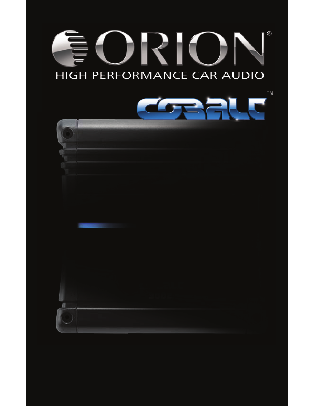
END PANEL LAYOUTS
Input Plate
Figure 1
Figura 1
Abbildung 1
CO3002
CO6002
Figure 2
Figura 2
Abbildung 2
1. Power LED - When lit indicates that the amplifier is on.
2. High Level Input - Connect speaker output from factory radio to amplifier, will auto
sense signal from radio and turn amplifier on when needed, turn off after 1 minute
© 2008 directed electronics—all rights reserved 3
Page 5
without signal.
23145
232145
3. RCA Inputs - Accepts RCA input from a source unit, preamplifier, or equalizer.
4. Gain Control - Continuously adjusts from 175mV to 8V input to obtain full power
output.
5. HPF, FULL, LPF Switch - Selects either Hi-pass crossover, Full range, or Lo-pass cross-
over.
6. Lo-Pass Frequency Control - Adjusts the frequency of the crossover.
7. Hi-Pass Frequency Control - Adjusts the frequency of the crossover.
8. Bass Boost Switch - Adjusts bass gain in three steps (0dB, 6dB, & 12dB).
9. Status LED - Will indicate any fault condition in amplifier, also lights briefly during
muting phase of turn-on
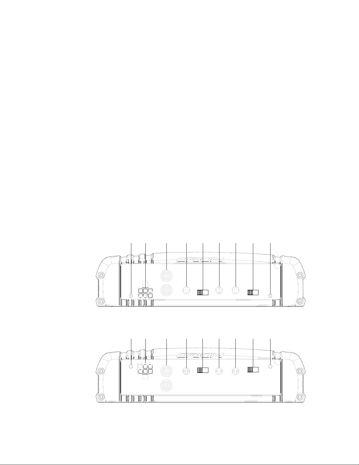
Output Plate
CO3002
Figure 3
Figura 3
Abbildung 3
CO6002
Figure 4
Figura 4
Abbildung 4
1. Speaker Connections - accepts up to 12 AWG speaker wire.
2. 1 ATC Fuse (CO3002) - 2 ATC Fuses (CO6002) - protects the amplifier from over
current situations.
3. Power Connections - accepts up to 4 AWG power cables.
4. REM Remote Turn-on Input - turns on the amplifier when fed 12 V+.
5. Ground Connection - accepts up to 4 AWG ground cable.
4 © 2008 directed electronics—all rights reserved
Page 6
CEA SPECIFICATIONS
CO3002
Power Output: 60 Watts RMS x 2 at 4 ohms and < 1% THD+N
Signal to Noise Ratio: -75 dBA (reference Watt into 4 ohms)
Additional Power: 80 Watts RMS x 2 at 2 ohm and < 1% THD+N
CO6002
Power Output: 100 Watts RMS x 2 at 4 ohms and < 1% THD+N
Signal to Noise Ratio: -75 dBA (reference Watt into 4 ohms)
Additional Power: 155 Watts RMS x 2 at 2 ohm and < 1% THD+N
HIGH LEVEL HARNESSES
Do not connect the high level input connections to power, signal, or chassis ground as damage
to the head-unit outputs may result. The high-level inputs are designed to work with either
grounded or BTL speaker level outputs (found on most head units).
HIGH LEVEL CONNECTIONS
WIRE COLOR INPUT CONNECTION
Black Ground
White/Black - Left channel
White + Left channel
Gray/Black - Right channel
Gray + Right channel
AMPLIFIER SETTINGS
Signal Input and Output Configurations
The input section of the amplifier consists of a phase switch that sets the output configuration,
gain controls, and RCA inputs. The input section makes it easy to adapt this amplifier to most
system configurations.
Input Gain
The Orion Cobalt CO3002 and CO6002 amplifiers have level adjustments to allow for easy integration with any source unit. The input sensitivity can be adjusted from 175mV to 8V. Refer to
Testing the System and Adjusting the Sound of the System sections of this guide for detailed
instructions on setting the gain.
© 2008 directed electronics—all rights reserved 5
Page 7

Internal Crossover
--++--++
Bridged Stereo
4Ω or 8Ω 2Ω or 4Ω
2Ω or 4Ω
The crossover section of the Orion Cobalt CO3002 and CO6002 amplifiers is continuously variable
and extremely flexible.
When using Orion Cobalt loudspeakers, minor deviations from the recommended frequency
ranges can provide superior results depending on your speaker locations and your vehicle
acoustics. Setting crossover frequencies higher than recommended will not cause damage and
may provide superior sonic results depending on your system's performance goals. Refer to your
loudspeaker owner's manual for assistance in choosing the proper crossover frequencies for
your system.
Low-Pass Crossover
The low-pass crossover is active with a 2nd order (12dB per octave) slope. The low-pass crossover
is continuously variable from 50Hz to 500Hz.
High-Pass Crossover
When the switch is to the left (FULL position), the high-pass crossover is bypassed. When the
switch is to the right (HPF position), the high-pass crossover is active. The high-pass crossover is
continuously variable from 50Hz to 500Hz.
AMPLIFIER WIRING
Power Connections for the Orion Cobalt CO3002 and CO6002
● Orion Cobalt CO3002 Fuse Size: 1 x 25 AMP ATC / CO6002 Fuse Size: 2 x 20 AMP ATC
● Power connections accept up to 4 AWG wire.
● 4 AWG power and ground wire recommended for optimal performance.
● Connect 12V+ to the battery through fuse holder. This connection provides +12V main
power to the amplifier.
● Power wire must be fused no more than 18" from battery.
● Ground amplifier to a good chassis ground as close as possible to the amplifier.
● Connect REM terminal to remote turn-on lead from source unit. This connection pro-
vides +12V power to turn-on the amplifier.
● Add extra ground wire between the negative terminal of the battery and the chassis.
Speaker Wiring Diagram CO3002/CO6002
The Orion Cobalt CO3002 and CO6002 amplifiers offer two positive and two negative output terminals for ease of connecting the speakers to the amplifier. Each amplifier is stable to 2 per channel
or 4 ohm bridged .
Figure 5
Figura 5
Abbildung 5
6 © 2008 directed electronics—all rights reserved
Page 8

Figure 6
--++
Bridged
Tri-mode
2Ω or 4Ω
2Ω or 4Ω
4Ω or 8Ω
Figura 6
Abbildung 6
Tri-mode
For Tri-mode wiring the high frequency speakers should be run in stereo and use a passive in
line crossover (capacitor) with each to remove the low frequency. The mono low frequency
speaker would be connected in the bridge mode to the two stereo channels with a in line passive crossover (inductor) to remove the high frequencies. The high frequency speakers should
be no less than 2 ohms and the low frequency speaker should be no less than 4 ohms.
Bridging
For bridging into a single speaker load, the Orion Cobalt CO3002 and CO6002 has the ability
to bridge the front or rear channels together. The impedance of the speaker must not be less
than 4
AMPLIFIER INSTALLATION
Choosing Mounting Locations
The location of your amplifier will depend on several important issues. Due to the low profile
size of the Orion Cobalt amplifiers, there are many possible installation locations that will yield
satisfactory amplifier performance. Always mount the amplifier in a place that protects the
amplifier from the elements. In addition, mount the amplifier on a stable, flat surface.
NOTE: Mounting amplifiers upside down is not recommended and may cause premature
thermal shutdown.
WARNING! Do not mount any amplifier in the engine compartment. Amplifiers are not
designed to endure the harsh environment of the exterior elements.
© 2008 directed electronics—all rights reserved 7
Page 9

Passenger Compartment
If you are going to mount the amplifier in the passenger compartment, make sure you have
adequate room for ventilation. The amplifiers have been designed to make under-seat mounting possible. When mounting your amplifier under a seat or similar area, keep a minimum of 1"
of clearance around the amplifier for adequate cooling.
Trunk Compartment
Mounting your amplifier in the trunk provides excellent performance as long as you do not
restrict the airflow around the heatsink of the amplifier. For optimal results, mount the amplifier
with as much clearance as possible. This type of mounting will yield the best cooling due to the
convection effect of the amplifier chassis.
General Precautions and Installation Tips
WARNING! Be careful not to cut or drill into gas tanks, fuel lines, brake lines, hydraulic lines,
vacuum lines, or electrical wiring when working on your vehicle.
Disconnect the vehicle's ground wire at the battery before making or breaking connections to
the audio system's power supply terminals.
Do not use this amplifier unmounted. Failing to securely mount the amplifier can result in
damage or injury, particularly in the event of an accident. An unmounted amplifier becomes a
dangerous projectile in the event of a crash. Never mount the amplifier where it might get wet.
Mount the amplifier so the wire connections will not be pulled. Route the wires where they will
not be scraped, pinched or damaged in any fashion.
The +12V power supply wire must be fused as close as possible to the battery terminal, ideally
within 18". Use the recommended fuse size or circuit breaker listed in the Power Connections
section of this manual.
If you need to replace the fuse plugged into the side of the amplifier, replace the fuse with the
same size ATC / MAXI type fuse that came with the amplifier. If you are not sure as to the correct
value, refer to the Power Connections section of this manual for details. Using a higher current
fuse may result in damage to the amplifier that is not covered under warranty.
NOTE: Make sure all the equipment in the system is turned off when making or breaking con-
nections to the input RCAs or speaker terminals. Turn on the system and slowly turn up
the volume control only after double checking all wire connections.
Power for systems with a single amplifier can be supplied by most automotive electrical systems.
Systems with multiple amplifiers may require a higher capacity battery, alternator or the use of a
storage capacitor. We strongly recommend the use of a Directed Audio Essentials power capacitor with an extra battery in larger stereo systems.
Orion Cobalt amplifiers generate a certain amount of heat as part of normal operation. Be sure
the area around the amplifier is unobstructed to allow adequate air circulation. Remember,
beach blankets, last week's laundry, school books and homework papers located on top of the
amplifier do not improve air flow and may become damaged.
Step By Step Installation
Step 1 Determine the location for the amplifier. Refer to the Choosing Mounting
Locations section of this guide for detailed information.
Step 2 Decide on the system configuration for your amplifier. For system suggestions,
refer to the Speaker Connections section of this guide.
8 © 2008 directed electronics—all rights reserved
Page 10

Step 3 Run all the wires from the amplifier location to the speakers, source unit, and bat-
tery. Do not connect the battery at this time. Be sure to run RCAs and power and
speaker wires away from factory electrical wires and system as they pose a great
potential for induced system noise.
Step 4 Pre-drill amplifier mounting holes. Be sure to "think before you drill". Gas tanks,
fuel lines, and other obstructions have a nasty way of hiding themselves. For best
results use a marking pen to mark the mounting holes and pre-drill these holes
with a standard 1/8" drill bit.
Step 5 Mount the amplifier. Make sure the amplifier is mounted on a flat surface. If this
is not possible, do not over tighten the screws so that the chassis of the amplifier
is twisted or bent.
Step 6 Turn the vehicle's key switch to the off position.
Step 7 Disconnect the vehicle's battery ground terminal.
Step 8 Connect power wires to the amplifier (ground first, then 12 V(+) and REM).
Step 9 Connect the RCA and speaker wires to the amplifier. Check the quality of your
speakers and signal connections. This will determine the ultimate performance of
your Orion Cobalt amplifier. Refer to the Signal Input and Output Level Controls
and Speaker Connections sections of this guide for correct wiring instructions.
Step 10 Reconnect the ground terminal to the battery after power, speaker, and RCA con-
nections are completed.
Step 11 Set crossovers. Refer to the Internal Crossover Configuration section of this manual
for detailed instructions.
Step 12 Once satisfied that all connections and settings are correct, install the fuse located
near the vehicle's battery and proceed to the Testing the System section of this
manual.
WARNING! Never exceed the recommended fuse size of this amplifier. Failure to do so will
result in the voiding of your warranty and possible damage to the amplifier.
SET UP AND TROUBLESHOOTING
Testing the System
After you have completed the installation, you need to test the system. This will help ensure years
of trouble-free operation. Please refer to the listed steps below when testing the sound of your
Orion Cobalt system.
Step 1 Check all the wiring connections to be sure they are correct and secure.
Step 2 Turn the signal source volume control all the way down. Set any tone controls to
their flat or defeated positions. This includes the loudness control.
Step 3 Turn the level controls of the amplifier to their minimum positions.
Step 4 Turn the source unit on. Check to see if the power LED located on the input
side of the amplifier is on. If not, please refer to the Power Connections and the
Troubleshooting Tips sections of this manual for instructions.
Step 5 If using an aftermarket source unit, turn the level controls of the amplifier about
one quarter of a turn. Slowly increase the volume level of the source unit to so that
you can hear the output of the system. If no sound is heard or if the output is distorted, turn the system off immediately. Refer to the Power Connections and the
Troubleshooting Tips sections of this manual to solve your installation problems.
Step 6 Check to make sure the output for each channel is correct. If the active crossovers
© 2008 directed electronics—all rights reserved 9
Page 11

are used, check to make sure that each output is correct from the amplifier. When
using active crossovers on midrange and tweeters, do not use crossover frequencies lower than recommended. If the system is not configured properly, refer to
the Internal Crossover Configuration section of this manual and take corrective
action.
Step 7 If the output is clear and undistorted, continue to the Adjusting the Sound of the
System section of this manual.
Adjusting the Sound of the System
Once you have checked the system's operation, adjust the sound of the system. Adjusting the
sound of the system is accomplished by setting the level controls and adjusting the internal
crossovers.
Step 1 Turn the signal source volume control all the way down. Set any tone controls to
their flat or defeated positions. This includes the loudness control.
Step 2 Turn the level controls of the amplifier to their minimum positions.
Step 3 Choose music with high dynamic content that you like, with which you are famil-
iar, and will be used most often in the system.
Step 4 Turn the source unit's volume control up to its highest undistorted output level. If
you lack test equipment, this point occurs between 3/4 to full volume depending
on the quality of your source unit. Listen for any audible distortion. If any distortion is audible, reduce the volume of the source unit until you have an undistorted
output. Leave the volume control at this position during your system tuning.
Step 5 While listening to your chosen dynamic music, turn up the level control corre-
sponding to the midrange output until you hear slight distortion and turn the
level control back slightly for an undistorted output. Depending on your system,
the midrange and tweeter output may be on the same output channels.
Step 6 Turn up the level control corresponding to the tweeter output until you hear
slight distortion and turn back the level control slightly for an undistorted output.
Depending on your system the midrange and tweeter output may be on the same
output channels.
Step 7 Fine-tune the output level between midrange and tweeters. Refer to the Internal
Crossover Configuration section of this manual for detailed instructions.
Step 8 Repeat Steps 5-7 for the rear speakers. If you do not have rear speakers continue
to Step 10.
Step 9 Set levels between the front and rear midrange and tweeters for optimum front/
rear balance.
Step 10 Turn up the level control corresponding to the woofer output until you hear slight
distortion and turn back the level control slightly for an undistorted output.
Step 11 Fine-tune the output level between satellite speakers and the woofers. Refer to
the Internal Crossover Configuration section of this manual for detailed instruc-
tions.
Step 12 Enjoy your awesome Orion Cobalt sound system.
10 © 2008 directed electronics—all rights reserved
Page 12

Troubleshooting Tips
Symptom Probable Cause Action To Take
No output
Low or no remote turn-on Check remote turn-on voltage at voltage
amplifi er and repair as needed.
Fuse blown Check power wire's integrity and check for
speaker shorts. Fix as needed and replace
fuse.
Power wires not connected Check power wire and ground connections
and repair or replace as needed.
Audio input not connected. Check RCA connections and repair or replace
as needed.
Speaker wires not connected Check speaker wires and repair or replace as
needed.
Speaker are blown Check system with known working speaker
and repair or replace speakers as needed.
Audio cycles on and off
Thermal protection engages
when amplifi er heat sink temperature exceeds 50º C (122º F)
Loose or poor audio input Check RCA connections and repair or replace
Loose power connections Check power wires and ground connections
Distorted output
Amplifi er level sensitivity set
too high exceeding maximum
capability of amplifi er
Impedance load to amplifi er
too low
Shorted speaker wires Check speaker wires and repair or replace as
Speaker not connected to amplifi er properly.
Make sure there is proper ventilation for amplifi er and improve ventilation as needed.
as needed.
and repair or replace as needed.
Readjust gain. Refer to the Adjusting the
Sound of the System section of this manual
for detailed instructions.
Check speaker impedance load, if below 2,
rewire the speakers to achieve higher impedance.
needed.
Check speaker wires and repair or replace as
needed. Refer to the Speaker Connections
section of this manual for detailed instructions
Internal crossover not set properly for speakers
Readjust crossovers. Refer to the Internal
Crossover Confi guration section of this
manual for detailed instructions.
Speakers are blown Check system with known working speakers
and fi x or replace as needed.
Poor bass response
Speakers wired with wrong
Check speaker polarity and fi x as needed.
polarity causing cancellation at
low frequencies.
© 2008 directed electronics—all rights reserved 11
Page 13

Symptom Probable Cause Action To Take
Poor bass response
Crossover set incorrectly Reset crossovers. Refer to the Internal Cross-
over Confi guration section of this manual for
detailed instructions.
Impedance load at amplifi er is
too low.
Battery fuse blowing
Short in power wire or incorrect wiring.
Fuse used is smaller than recommended.
Actual current exceeds fuse
rating.
Amplifi er fuse blowing
Fuse used is smaller than recommended.
Impedance load at amplifi er is
too low.
Speaker is blown with shorted
outputs
Actual current exceeds fuse
rating
Check speaker impedance load if below 2,
rewire speakers to achieve higher impedance
.
Check power wires and ground connections
and repair or replace as needed.
Replace with proper fuse size.
Check speaker impedance load if below 2,
rewire speakers to achieve higher impedance
.
Replace with proper fuse size.
Check speaker impedance load if below 2,
rewire speakers to achieve higher impedance
.
Check system with known working speakers
and fi x or replace as needed.
Check speaker impedance load if below 2,
rewire speakers to achieve higher impedance
.
12 © 2008 directed electronics—all rights reserved
Page 14

SPECIFICATIONS
Amplifi er Section CO3002 CO6002
Power Output in Watts RMS, 4 Ohms 60 x 2 100 x 2
Power Output in Watts RMS, 2 Ohms 80 x 2 155 x 2
Distortion at Rated Power < 0.5% THD+N < 0.7% THD+N
Frequency Response 20Hz to 30kHz
+/-0.5dB
Linear Bandwidth 20Hz to 20kHz
±3dB
Damping Factor > 100 > 100
Input Sensitivity 175mV - 8V 175mV - 8V
Input Impedance > 15k > 10k
Fuse Type (1) 25 Amp, ATC (2) 20 Amp, ATC
Dimensions 2.1" x 8.1" x 7.9" 2.1" x 8.1" x 11.4"
Weight 4.5 lbs. 6.3 lbs.
Crossover Section
Low Pass and Hi-pass crossover Continuously variable/
2nd Order
Crossover Frequency Range 50Hz to 500Hz 50Hz to 500Hz
Continuous 2 load 20Hz to 200Hz, < 0.1% THD, with input voltage at 13.8VDC
20Hz to 30kHz
+/-0.5dB
20Hz to 20kHz
±3dB
Continuously variable/
2nd Order
© 2008 directed electronics—all rights reserved 13
Page 15

™
WARRANTY
LIMITED ONE-YEAR CONSUMER WARRANTY/*LIMITED TWO-YEAR CONSUMER WARRANTY FOR AUTHORIZED
DIRECTED DEALER PURCHASE & INSTALLATION
Directed Electronics (herein “Directed”) promises to the original purchaser of the subwoofer or amplifier, as
applicable (herein “Unit” or “Product”), to repair or replace with a new or refurbished Unit (at Directed’s
sole and absolute discretion) should the Unit prove to be defective in workmanship or material under normal
use, for a period of *two-years from the date of purchase from the authorized Directed dealer PROVIDED
the Unit was purchased and installed by an authorized Directed dealer. During this *two-year period, there
will be no charge for the repair or replacement PROVIDED the Unit is returned to Directed (DO NOT RETURN
THE ENTIRE ENCLOSURE. PLEASE RETURN THE WARRANTIED UNIT ONLY.), shipping prepaid, along with the
required proof of installation, the bill of sale or other dated proof of purchase, and the consumer’s contact
information. If the Unit is installed by anyone other than an authorized Directed dealer, the warranty period
will be one-year from the date of purchase. This warranty is non-transferable and does not apply to any Unit
that has been modified or used in a manner contrary to its intended purpose, and does not cover damage to
the Unit caused by installation or removal of the Unit. During this one-year period, there will be no charge
for the repair or replacement PROVIDED the Unit is returned to Directed, shipping pre-paid, along with
the bill of sale or other dated proof of purchase and the consumer’s contact information. This warranty is
void if the product has been damaged by accident or unreasonable use, neglect, improper service or other
causes not arising out of defects in materials or construction. This warranty does not cover the elimination
of externally generated static or noise, or the correction of antenna problems or weak reception, damage to
speakers, accessories, electrical systems, cosmetic damage or damage due to negligence, misuse, failure to
follow operating instructions, accidental spills or customer applied cleaners, damage due to environmental
causes such as floods, airborne fallout, chemicals, salt, hail, lightning or extreme temperatures, damage due
to accidents, road hazards, fire, theft, loss or vandalism, damage due to improper connection to equipment
of another manufacturer, modification of existing equipment, or Product which has been opened or tampered for any reason. Units which are found to be damaged by abuse resulting in thermally damaged voice
coils are not covered by this warranty but may be replaced at the absolute and sole discretion of Directed.
Unit must be returned to Directed (DO NOT RETURN THE ENTIRE ENCLOSURE. THE UNIT ENCLOSURE IS COVERED BY A SEPARATE 90-DAY LIMITED CONSUMER WARRANTY. PLEASE ONLY RETURN THE WARRANTIED
UNIT UNLESS A WARRANTY CLAIM IS BEING MADE FOR THE ENCLOSURE.), postage pre-paid, with bill of sale
or other dated proof of purchase bearing the following information: consumer’s name, telephone number,
and address, authorized dealer’s name and address, and product description. Unit must be returned to the
following address: ATTN: WARRANTY DEPARTMENT, Directed Electronics , 1 Viper Way, Vista, CA 92081. Note:
This warranty does not cover labor costs for the removal and/or reinstallation of the Unit. IN ORDER FOR
THE TWO-YEAR WARRANTY TO BE VALID, YOUR UNIT MUST BE SHIPPED WITH PROOF OF INSTALLATION BY
AN AUTHORIZED DIRECTED DEALER. ALL UNITS RECEIVED BY DIRECTED FOR WARRANTY REPAIR WITHOUT
PROOF OF DIRECTED DEALER INSTALLATION AND PURCHASE WILL BE COVERED BY THE LIMITED 1 YEAR
WARRANTY.
BY PURCHASING THIS PRODUCT, ALL WARRANTIES INCLUDING BUT NOT LIMITED TO EXPRESS WARRANTY,
IMPLIED WARRANTY, WARRANTY OF MERCHANTABILITY, FITNESS FOR PARTICULAR PURPOSE, AND WARRANTY OF NON-INFRINGEMENT OF INTELLECTUAL PROPERTY ARE EXPRESSLY EXCLUDED TO THE MAXIMUM
EXTENT ALLOWED BY LAW, AND DIRECTED NEITHER ASSUMES NOR AUTHORIZES ANY PERSON TO ASSUME
FOR IT ANY LIABILITY IN CONNECTION WITH THE SALE OF THE PRODUCT. DIRECTED HAS ABSOLUTELY NO
LIABILITY FOR ANY AND ALL ACTS OF THIRD PARTIES INCLUDING ITS AUTHORIZED DEALERS OR INSTALLERS.
IN NO EVENT WILL DIRECTED BE LIABLE FOR ANY INCIDENTAL, SPECIAL OR CONSEQUENTIAL DAMAGES (INCLUDING LOSS OF PROFITS). BY PURCHASING THIS PRODUCT, THE CONSUMER AGREES AND CONSENTS THAT
ALL DISPUTES BETWEEN THE CONSUMER AND DIRECTED SHALL BE RESOLVED IN ACCORDANCE WITH CALIFORNIA LAWS IN SAN DIEGO COUNTY, CALIFORNIA. This warranty is only valid for sale of Product within the
United States of America. Product sold outside of the United States of America is sold “AS-IS,” and shall have
NO WARRANTY, express or implied. Some states do not allow limitation on how long an implied warranty
lasts. In such states, the limitation or exclusions of this Limited Warranty may not apply. Some states do not
allow the exclusion or limitation of incidental or consequential damages. In such states, the exclusion or limitation of this Limited Warranty may not apply to you. This Limited Warranty gives you specific legal rights,
and you may have other rights which vary from state to state. 920-0033 04-07
For more information on Orion products please visit www.orioncaraudio.com
Directed Electronics is committed to delivering
world class quality products and services
Directed Electronics is an
ISO 9001 registered company.
© 2008 Directed Electronics. All rights reserved. GCO3002 2008-10
that excite and delight our customers.
Vista, CA 92081
DIRECTED.COM
Page 16

Please
correspondence
Directed
1
Vista,CA92081
Viper
send
products
Electronics
Way
XFA01-01
to:
and
Inc.
other
First·Class
Postage
Required
Post Office will
not deliver
without proper
postage.
E l E C T
PO BOX 174391
DENVER CO 80217-4391
11..1.11.
PRODUCT
REGISTRATION
RON
I C5,I N
....
1.1"11111..111..1..1111.1"1..111.1"11111.111.1
=-
--------
c.
~ ~
E
LEeTRON
Audio/Video
I CS.INC.
.
-::w.
_.
_
RETURN
•
Product
With
This
•
ProofofOwnership
Your
forupto
THIS
Protection
the
information
confirmationisof
model
number,
ten
years.
CARD
you
providewecan
benefittoyou,
serial
number,
NOW
confirm
especiallyifyour
and
other
FOR:
the
dateofpurchaseofyour
information
original
proofofpurchaseislost.
willbekeptinour
product.
files
Page 17

1.
1._~Mr.
First
ELECTRONICS,
Name
IMPORTANT! IMPORTANT!
Please
complete
and
return
within
the
INC.
3
Mrs.
..
2.
r]
Ms.
r-
4.
, j
MIss
Initial last
.
or
register
onlineatwww.prodregister.com/directed
Name
next10days
XFA01·01
Street
City
E·mail
2.
Your
3.
Marital
4.
Date01purchase:
Month
5.
Model
6.
Nameofstore
7.
Price
8.
Which
1.
2
9.
What
I.
2
3.
4
10.
What
1.
2.
3
4.
11.
In
what
Makeofvehicle:
Model
VIN
Year'
12.
How
01
02
03
05
Ot.
Whallactors
13.
01
02
03
0'
05
06
07
08
09
10
What
14.
purchase?
0;
02
03
04
05
06
01.
08
09
to
daleofbirth:
status:
number:
Ilaitl
Directed
product
IYlle01vehicle
vehicle IVililhis
name:
#:
did
you
benefits
Month
Married
1.
/ /
Oav
where
purchased:
(eKGluding
s~les
tax): $
Electronics
Directed
Orion
Precisior.
did
Subwooter
Speaker
Amoillie;
Signa!
Car
liuck
SUV
Van
MiniVan
!irsl
LocainewS03iJel
Vellow
Magazme
adverhsemem
T"
..
MaOliZine
f€Vle'
Friend/Relative's
r~comrnendalIO!~
most
Directed
8ranc's
Experience
Directed
EXDeneilce
Value/Price
Warranty
SpeCia!
QualityiOurab!ht~
SounG
defP.O
RebatelPromotlOn
ollhis
(cheel{UDto
Impro
quall!v
Improved
SPL
Improved
AbllitvtowalclllllCVle
m
vehicie
Usedbyautosound
competitors
CompatibIlity
vehicle
Ease
Style/Design/COlOr
SpecIal
OualiNiOurabili~1
brand
AudiO
Powe;
you
purchase?
Processor
willihis prodllclbeused
productbe"sed?
become
aware01this producl?
pages
,,!:.~.:.,
artIcle
....
·
influenced
s
rep:l:atlOn
repUiatlOn
\'Jffn
producT
wln~
dealer
feawr(:!<;
boardilil-vr.hlcle ; 7
produc!
most
three}
....
ed
SQufic'
loudness
pEr
formance
WIU'1
of
installation
featuf%
/
Yea;
4.
5.
6.
5.
6.
7
8.
6.
07.
08
09.
10.
t;.
the
Year
2.'
did
you
Xtreme
aid/sl
Directed
Complete
Overhead
headresl
DVD
Motorcycle
Boai
Motor
Ollw
purchase?
1;.
12
~
3
i·~
i5
16
13.
inlluencert
,.)
13.
1
~
15.
10
1:
15.
IS
20.
Single
.00
purchase?
V:deo
Video
Manllor
MOIlIior
Player
in?
IlOme
!j()U\111:
BC'IJOht
Leased
Leasetj
fchec~
RadIO
conHllerCI?1
Salesperson
s
recommendatloP
Molorsports
lmernc\
Omer
rcneckupto
Style:OeslgwColar
De3.ler
pfoxlimly
Friend's
recormilenclation
Sal8sPW50P
recommerlclalror-;
case
of
Installation
COlllpatiDllitv
venicle
Orne:
Other
Directed
only
your
decision
Increase
vehicle
vaiUf
t:unciionallty
Warranty
Pri:::eiValut':
Rebate/Promotio"
Immediate
availabilll)
FtI~l1c's
recommendation
Salesoerson
recommendal:ol'
Dealer
woxlml:~;
Otner
System
New
Usco
U':'tni
')ne
tnree)
\'Jln
brands
Apt.
No.
Stale
15.
What
other
this
purchase?
..
01.
02
03.
04.
05.
06.
07.
08.
16.
Which
(three
01.
02.
03
O.:i.
05.
06.
07.
OS
09.
10.
Nol
including
17.
of
children
1.INo
Male
Female
18.
Occupalion:
Prof!:!sslonal:lcchnlcal.
Upper
MIddle
SJI~sfMarkellnQ..
Cle'iC3.lfSerVlce
Tradesman/Macnine
19.
Are
youoryour
t\
rlomt"'Hl1aker?
Hetlrerl?
,\
Sluden:~
S;;lf
fmoioy
20.
Working
IiI
tile
AVelersn?.
Which
0:.
02.
O~
O~
05
OC.
0;
l
21. level
2:.
2.
22.
Which
1.
L.
r!
4.
23.
For
your
1.
24.
How
3 Withlll 4 - 6
25.
Whichofthe
6or12
Buy/LeaseaNew
Buy/Lease
recentlV
to
ZIP
Code
brands
did
you
seriously
consider
None.
only
Directed
Eleclronics
Other
Directed
brands
oniy
Audiovox
MTX
MB
Ouart
Rockford
JL
Audio
Rosen
oflhe following publicalionsdoyou
oul01the
last
Car
and
Oriver
Oar
Audio
Electronics
Car
Sound
Performance
Hot
Baal
Imoort
Tuner
Import
Racer
Lowrider
Mini
Iruckln'
MOtor
Trend
Performance
&
50una
yourself.
and
other
one
elseinhousehold
Age
{check
Management'txecu{lve
Manaqemept
Worker
spouse:
eci/3uSlfl8SS
Iron:£:HOI1lB
MiIIHlr~J?
..
group
describes your
Under
515.000
$15000-$19.99£
S2l;
OU0-:529
530.000-539.999
540000-549.999
550.000-559.999
560.000-574.999
01
education:
Completed
Completed
Completed
credit
cardsdoyou
f\meftcar.
MasterCard.
Department
Ot)
not
use
primary residence.doyou:
Own?
did
you
W,lhrn30d2Ys
WIthin
1- 3
lollowingdoyou
monlhs?
Vehicle
a
Used
V".!hlcle
PLEASE
09.
tnc.
to.
11.
12.
13.
14.
15.
Fosgate
16.
17.
t8.
four
issues)?
11
&
12.
13.
an~
1-1.
15.
16
1;.
t8.
19.
20
21.
Auto
2'2
23.
whatisIhe
adults
Jivinginyour
Male
vrs.
1.
yr,;:;.
ai'
r\il1
applv'
Ooerator'Laoorer
Owner7
Office'(
annual
08
as.
!J9~
11
t2
:3.5200000·5249.999
14
/check
highesi
High
Scnoo:
College
Graduat!?
SChOol
use
regularly?
Express.
Diners
Visa.
Discover
StorE.
Oil
credl!
cardS
move
in1~
months
months
planfodo
..
..
CONTINUEONBACK
(e/Jeck
"
GENDER
2.
Female
..
family
level
completed)
Club
Company.
2.
your current
4 7
5.
before
making
Polk
Audio
Audiobahn
Memphis
Kicker
Alpine
Sony
Kenwood
Pioneer
ClariOn
Other
read
regularly
al/lhat
apptYi
Road&Track
Rolling
Stone
5KATEboarding
Ski
Snowboard
5010
Sport
Compact
5port
Truck
Street
Trucks
Super
Stree'
Truckin'
Working
Woman
Other
and
AGE
(in
household?
Child
under
Age
2.
You
Spouse
3.
4
5
G.
You
5pouse
4.
5
6
7.
income?
S75000·599.999
5100,000-$124,999
~
i:J
J'.JO-S:
etc
residence?
te12months
Have
the
las:t2monlhs
within
1-6
not
the
1.
~
~~.Jj;
moved
nexi
Months
~ ~
5150.000-5174999
5175.000-5199.999
5250.000&aver
Reo!?
Monlhs
Ca~
years)
1
VOl:ar
7·12
yrs
yrs
ago
In
Page 18

--
26.
Please
01.
LJ
02.
[_-I
03.
[J
04.
!:J
05.
r--:
06.
[J
check
all
that
applytoyour
ShopbyCatalog/Mail
Shop
via
the
Internet
MemberofFrequent
DonatetoCharitable
OwnaCompact
HaveaDog
Disc
household.
Flyer
Program
Causes
Player
07.
08.
09.
10.
11.
12.
[J
HaveaCat
CJ
OwnaWireless/Cellular
LJ
Subscribetoan
0
Speak
0
OwnanApple/Macintosh
L]
OwnaCD-ROM
Spanish
Phone
Online/Internet
Computer
Drive
Service
27.
To
helpusunderstand
enjoy
01.
02.
03.
04.
05.
06.
07.
08.
09.
10.
11.
12.
13.
14.
15.:__.1Flower
16.
17.
participatingona
l~~l
Bicycling
CJ
Golf
[l
Physical
[J
Running/Jogging
[J
Snow
[J
Tennis
r--'
Camping/Hiking
i---:
Fishing
[:
Hunting/Shooting
C,'.i
Powerboating
[~]
Sailing
[-_~]
Grandchildren
[J
Needlework/Knitting
[J
Sewing
Skiing
Gardening
0
Vegetable
:--1
Crafts
our
customers'
regular
basis.
Fitness/Exercise
Gardening
lifestyles,
18.
19
, '-;
20.
21
· '----'
22.
23
• L-..J
24.
25
• :.
26.
27
•
28
·
29
·
30.0
31
·
32.
33.
34.
please
[]
:---1
[J
ri
r.
j
[~~j
r--·'.
, ,
[J
r---'
....J
[~]
~--·l
I i
L._._i
..
--"
L_J
1---"1
~_J
..---,
, ,
,-._,
[J
C
:-l
indicate
Buy
Prerecorded
Automotive
the
interests
Work
Videos
Electronics
Home
Recreation
Workshop/Do-lt-
Vehicles
ListentoRecordslTapes/CDs
Avid
Book
Reading
Bible/Devotional
Health/Natural
Reading
Foods
Photography
Cultural/Arts
Fashion
Art/Antique
Foreign
Cruise
Ship
Events
Clothing
Collecting
Travel
Vacations
TravelinUSA
Gourmet
Cooking/Fine
Yourself
(RVs)
Foods
and
activitiesinwhich
35.
36.
37.
38.
39.
40.
41.
42.
43.
44.
45.
46.
47.
•
48.
49.
50.
51.
youoryour
Wines
[J
Stamp/Coin
:~]
Collectibles
CJ
Our
Nation's
[~;
Real
Estate
[]
Stocks/Bond
[J
Contests/Sweepstakes
;--:
Casino
:_~~]
Science
Wildlife/Environmental
L-_~~
DietinglWeight
r-l
Science/New
~_J
Self-Improvement
':
Walking
Watching
[J
Home
[J
Moneymaking
Collecting
Heritage
Investments
Gambling
Fiction
for
Health
SportsonTV
Video
Recording
spouse
Investments
Issues
Control
Technology
Opportunities
28.
Using
Thanks
important
information
thoseinwhich
Failuretoreturn
..
Copyright © 2004 All Rights Reserved
for
the
taking
mailings
indicated
you
this
numbersinthe
the
timetofill
and
are
card
special
above.
not.
will
offers
Through
Please
not
diminish
above
out
this
Questionnaire,
fromanumberoffine
this
selective
check
here
your
list,
please
program,
if.
for
some
warranty
Your
reason,
rights,
indicate
answers
companies
you
your3most
willbeused
whose
willbeabletoobtain
you
would
prefer
important
for
products
more
norto
activities:
market
participateinthis
research
and
services
information
relate
studies
about
opportunity.:_:
and
reports.
directlytothe
activitiesinwhich
They
specific
you
will
also
interests,
are
involved
allow
youtoreceive
hobbies.
and
540-0026 (A)
Please seal with tape. Do not staple.
and
less
other
about
 Loading...