

Page 1
www.orioncontrols.com
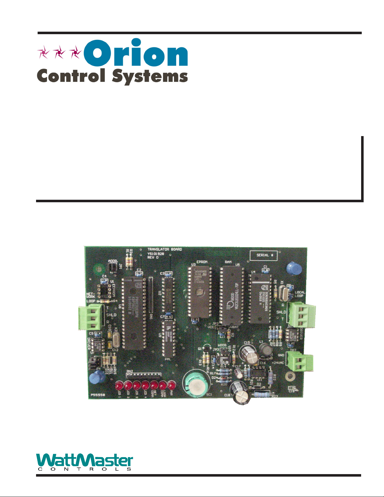
BACnet® Link
Technical Guide
Revision- 02B - August 2005
Page 2

Table Of Contents
General Information ........................................................................................................................................ 3
Data Sharing............................................................................................................................................................................... 3
Scheduling .................................................................................................................................................................................. 3
Hardware Specifications ............................................................................................................................................................. 3
Connection and Wiring Information ................................................................................................................ 4
Troubleshooting Information .......................................................................................................................... 5
General Information .................................................................................................................................................................... 5
Using LED’s To Verify Operation ................................................................................................................................................ 5
Programming- General Information ................................................................................................................ 6
BACnet® Link Overview ............................................................................................................................................................. 6
BACnet® Link Device Object...................................................................................................................................................... 6
WattBacObjectTypes .................................................................................................................................................................. 6
Local Address (MAC address).................................................................................................................................................... 6
BACnet® Services Supported ................................................................................................................................................... 6
MS/TP LAN Baud Rate............................................................................................................................................................... 6
Programming - Standard Objects ................................................................................................................... 7
General Information .................................................................................................................................................................... 7
Parameters ................................................................................................................................................................................. 7
Instance Number Base ............................................................................................................................................................... 7
MUA II Instance Number Base ................................................................................................................................................... 7
MUA II BACnet® Property Identifier ........................................................................................................................................... 8
VAV/CAV Instance Number Base ............................................................................................................................................... 9
VAV/CAV BACnet® Property Identifier ....................................................................................................................................... 9
CW/HW Instance Number Base............................................................................................................................................... 10
CW/HW BACnet® Property Identifier........................................................................................................................................11
Parameter Instance Numbers................................................................................................................................................... 12
Programming - Proprietary Objects .............................................................................................................. 13
BACnet® Link Overview .......................................................................................................... ................................................. 13
MUA II Object............................................................................................................................................................................ 13
MUA II Property Identifier ......................................................................................................................................................... 14
VAV/CAV Object ....................................................................................................................................................................... 15
VAV/CAV Property Identifier ..................................................................................................................................................... 16
CW/HW Object ......................................................................................................................................................................... 17
CW/HW Property Identifier ....................................................................................................................................................... 18
Proprietary Object Instance Numbers ....................................................................................................................................... 19
Appendix 1 ..................................................................................................................................................... 20
BACnet® Link Protocol Implementation Conformance Statement........................................................................................... 20
WattMaster Controls Inc.
8500 NW River Park Drive · Parkville , MO 64152
Toll Free Phone: 866-918-1100
PH: (816) 505-1100 · FAX: (816) 505-1101 · E-mail: mail@wattmaster.com
Visit our web site at www.orioncontrols.com
Form: OR-BACNET-TGD-02B Copyright 2005 WattMaster Controls, Inc.
AAON® is a registered trademark of AAON, Inc., Tulsa, OK.
®
BACnet
is a registered trademark of ASHRAE Inc., Atlanta, GA.
WattMaster Controls, Inc. assumes no responsibility for errors, or omissions.
This document is subject to change without notice.
Page 3
General Information
Technical Guide
The OE367-22 BACnet® Link provides bi-directional translation of
data and information between BACnet® devices and Orion VAV/CAV,
CW/HW and MUA II unit controllers.
Up to 16 total, Orion VAV/CAV, CH/HW, MUA II or any combination
of these controllers may be connected to each BACnet® Link. Up to 4
BACnet® Links can be used on a Orion Controls system allowing for
a maximum of 64 total controllers to be used.
Data Sharing
The BACnet® Link interface provides the following data sharing capabilities:
• Provides values from points on the Orion side of the
gateway to BACnet
originating from BACnet
• Allows BACnet
Orion controller side of the BACnet
standard BACnet® write services
®
devices as if the values were
®
objects.
®
devices to modify point values on the
®
Link by using
Scheduling
®
services
®
devices to send Schedule events
• Ability to allow BACnet
to the Orion controller side of the gateway by using
standard BACnet
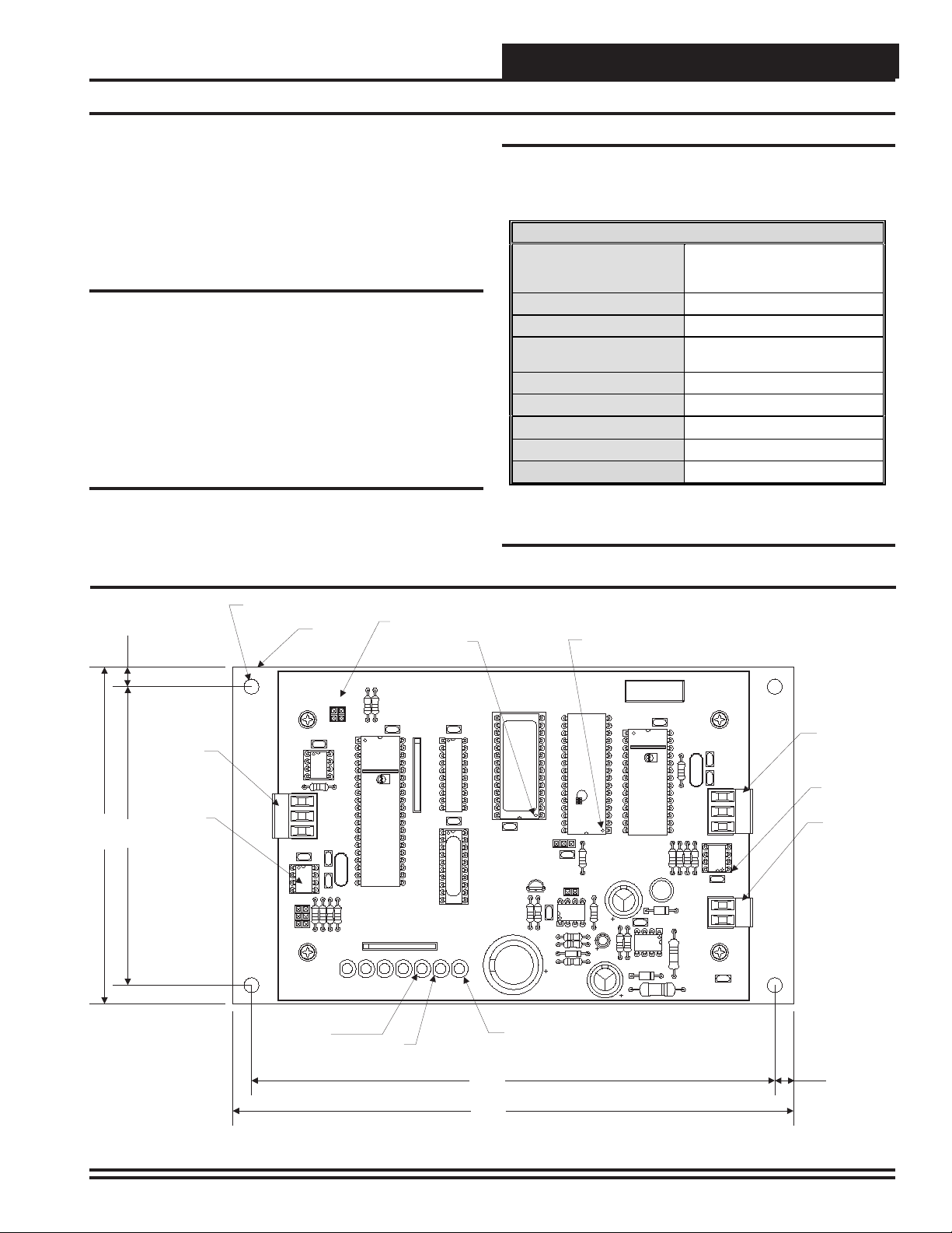
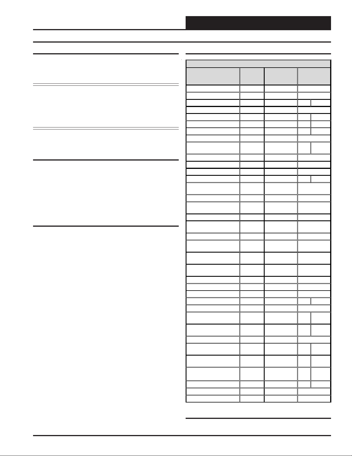
Hardware Specifications
Table 1 below contains the hardware specifications for the BACnet
Link interface.
Technical Data
BACnet Loop
Controller Loop
Protocol (BACn et Loop)
Protocol
(Wa ttMa ster L o o p)
Power Input Voltage
Power Consumption
Operating Temp
Operating Humidity
Weight
Table 1: BACnet® Link Interface Technical Data
RS-485, Auto Detect Host
Matching - 9600, 19200, 38400,
76800 Baud Rates
RS-485, 9600 Baud
MS/TP Lan
HSI Open Protocol
Token Passing
24 VAC
10 VA Maximum
10°F to 149°F
90% RH N on-Condensing
8 oz
®
4.50"
0.25”
4.00”
Network (MSTP)
Communications
Wiring Terminal
Network
Driver Chip
0.20 Dia.
Mounting Hole
Typ. 4 P L.
NET-
WORK
LOOP R4
C9
DRIVER
U7
TERM.
Mounting
Backplate
ADDR.
2
C4
U1
EEPROM
T
SHLD
R
C10
C12
R15
R11
R10
R18
JP4
Network
Communications
LED
R1
R3
JP1
1
U6
X2
RN2
LED 1
LED 2
LED 3
Local Loop
Communications
LED
Address Switch
EPROM Chip
Pin 1 Indicator
TRANSLATOR BOARD
YS101928
REV 0
C2
U2
RN1
U9
NET
COMM
LED 4
C3
C7
LOOP
COMM
PWR
7.00"
U3
C8
EPROM
Q1
R13
Power
LED
RAM Chip
Pin 1 Indicator
RAM
JP2
VCC VBAT
R16
R2
C11
WDOG
U10
JP3
C14
R14
R17
D2
R20
SERIAL #
U5
R12
C17
C1
U4
R19
R21
R5
X1
C5
LOCAL
C6
LOOP
R
SHLD
T
L1
R6
R7
R8
R9
D1
GND
C16
+24VAC
R22
U11
D3
R23
(+)
(-)
U8
DRIVER
C13
TB3
C19
Local Loop
Communications
Wiring Terminal
Local Loop
Communications
Driver Chip
24 VAC Power
Terminals
0.25”
7.50"
Figure 1: BACnet® Link Board Components and Dimensions
BACnet® Link Interface 3
Page 4
Technical Guide
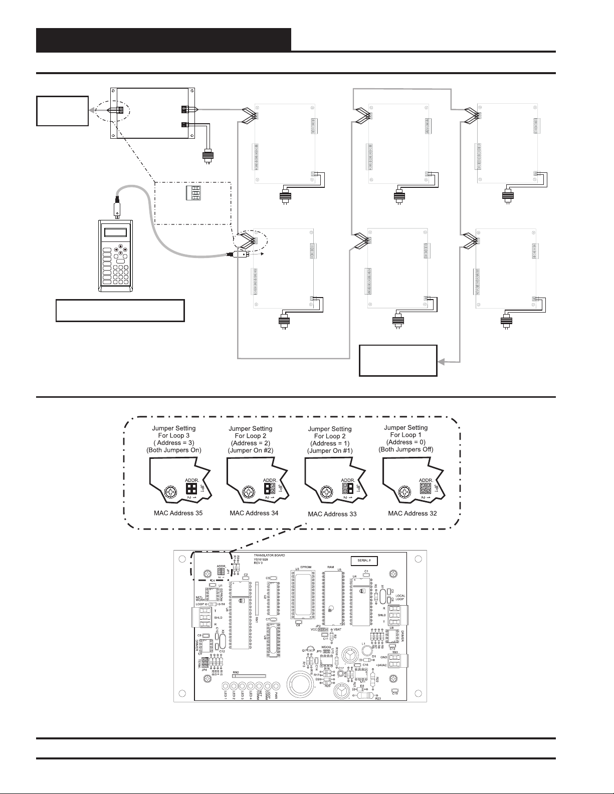
Connection and Wiring Information
BACnet Link Interface
BACnet MS/TP
LAN Connection
To BACnet
Network
Line Voltage
VAV/CAV or MUA II Unit Controller
24 VAC
(10 VA)
VAV/CAV or MUA II Unit Controller
VAV/CAV or MUA II Unit Controller
T
SHLD
R
Mode
Selection
STATUS
SETPOINTS
SCHEDULES
OVERRIDES
ALARMS
CONFIGURATION
BALANCE-TEST
ON
UP
PREV
DOWN
ESC
ENTER
13
2
708
DEC
Typical Terminal Blocks. All
Wiring To Be T To T, SHLD
(G) To SHLD (G)&RToR
NEXT
CLEAR
654
9
MINUS
-
Modular Service Tool
All Programming Of Unit Controllers
Must Be Done With The Modular Service Tool
Figure 2: BACnet® Link Interface Wiring
24 VAC
(8 VA)
Line Voltage
VAV/CAV or MUA II Unit Controller
24 VAC
(8 VA)
Line Voltage
24 VAC
(8 VA)
Line Voltage
VAV/CAV or MUA II Unit Controller
24 VAC
(8 VA)
Line Voltage
To Next VAV/CAV or MUA II
Controller On Loop
Up To 16 Controllers
Can Be Interconnected
24 VAC
(8 VA)
Line Voltage
VAV/CAV or MUA II Unit Controller
24 VAC
(8 VA)
Line Voltage
Figure 3: BACnet® Link Interface Address Switch Setting
4
BACnet® Link Interface
Page 5
Troubleshooting Information
Technical Guide
General Information
The BACnet® Link is designed to only work with the following Orion
controllers.
VAV/CAV Controller (SS1003, SS1012, Y200235, Y200301)
MUA II Controller (SS1004, Y200231, Y200306, Y200405)
CW/HW Controller (Y200311)
To determine what controller you have you must look at the label located on the controller E-prom. If the controller label does not match
any of the SS or Y numbers listed above, your controller will not work
with the BACnet® Link.
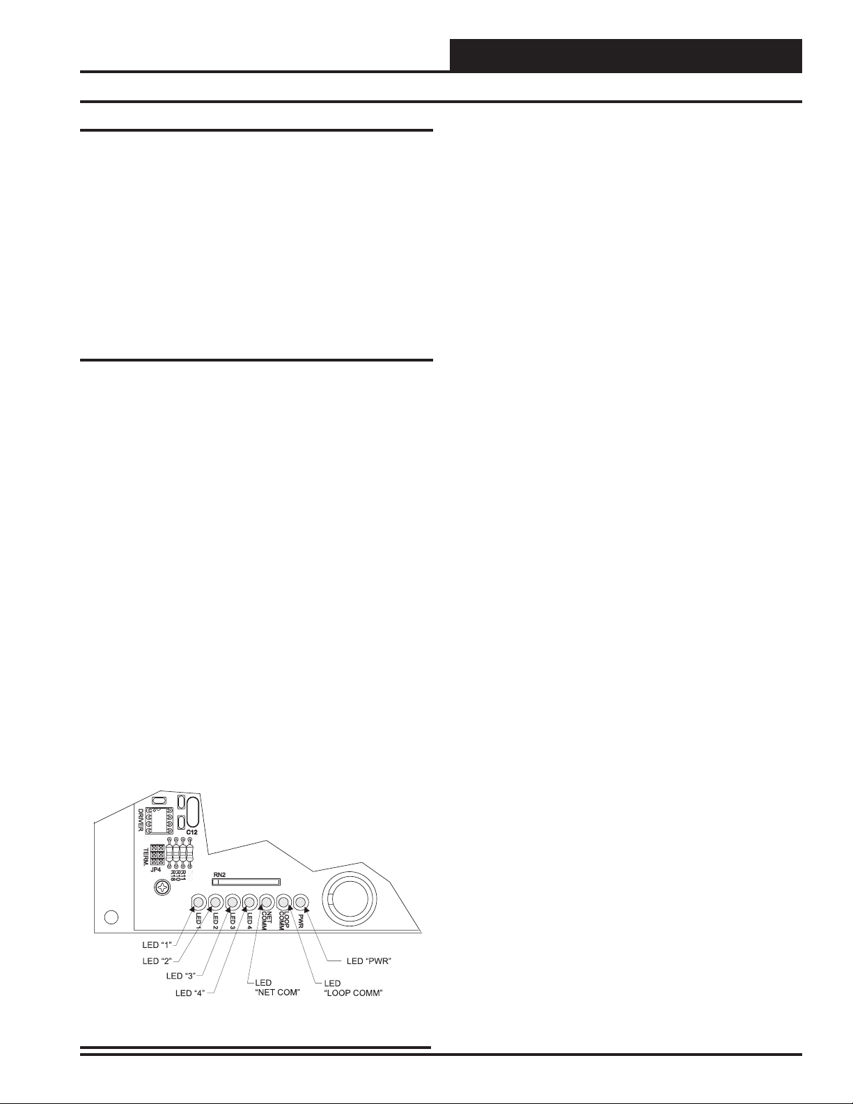
Using LED’s To Verify Operation
The BACnet® Link is equipped with LED’s that can be used for troubleshooting. There are seven LED’s on the BACnet® Link. Five of these
LED’s are used in troubleshooting. The LED’s and their uses are as
follows:
PWR
This LED will light up to indicate that 24 VAC power has been applied to the controller.
LOOP COMM
This LED will light up to indicate communication with the controllers
on the loop.
NET COMM
This LED will light up to indicate communication with the BACnet®
router.
LED 4
This LED is not currently used.
LED 3
This LED is also used to indicate communication with the BACnet®
router.
LED 2
This LED is used to indicate the number of controllers the BACnet®
Link is communicating with.
LED 1
This LED is not currently used.
PWR LED Operations
When the BACnet® Link is powered up, the “PWR” LED should light
up and stay on continuously. If it does not light up, check to be sure
that you have 24 VAC connected to the board, that the wiring connections are tight and that they are wired for correct polarity. The 24
VAC power must be connected so that all ground wires remain common. If after making all these checks the PWR LED does not light up,
please contact WattMaster technical support for assistance.
LOOP COMM LED Operations
When power is applied to the BACnet® Link the “LOOP COMM”
LED will also light up. The LED should flicker rapidly indicating
that the BACnet® Link is trying to communicate with the controllers
on the loop. A “flicker” is defined as a brief moment when the LED
turns off then back on. If the LOOP COMM LED does not operate as
indicated above, first power down the unit and then reapply power. If
this does not work, then contact WattMaster technical support for assistance.
LED 2 Operations
When power is first applied, “LED 2” will be off temporarily then will
blink one time for each controller it is communicating with. For example, if you have 10 controllers on the loop connected to the BACnet® Link then LED 2 will blink 10 times. If the amount of blinks
does not match the number of controllers connected to the loop, it
indicates there is a communications problem. The best way to find
out which board is not communicating is to go to each controller and
look at its COMM LED. The LED should be solid and will flicker
occasionally indicating communication with the BACnet® Link. If
the COMM LED does not flicker, there is no communication with that
controller.
NET COMM LED Operations
The “NET COMM” LED works the same way as the LOOP COMM
LED but it indicates that the BACnet® Link is trying to communicate
with the BACnet® router.
Figure 4 BACnet® Link LED Locations
BACnet® Link Interface
LED 3 Operations
When power is first applied , “LED 3” will be off temporarily and
then will blink slowly indicating communication with the BACnet®
router. If LED 3 does not blink, this means it is not communicating
with the BACnet® router. The first thing to check is the wiring between the BACnet® Link and the BACnet® router. Make sure that T
is wired to the (-) terminal of the router and R is wired to the (+)
terminal of the router.
If all of these tests are made and the controller still doesn’t operate,
please contact W attMaster Controls Technical Support at our T oll Free
number, 866-918-1100 for assistance.
5
Page 6

Technical Guide
Read
Programming- General Information
BACnet® Link Overview
The BACnet® Link provides the communications interface between the
Orion system and a BACnet® network. One BACnet® Link can support
up to sixteen controllers. The BACnet
network using Master-Slave/Token Passing (MS/TP) LAN data link
protocol.
The BACnet® Link supports 3 different controller types (device objects). These are the Orion MUA II, VAV/CAV and the CW/HW controllers.
®
Link connects to the BACnet
BACnet® Link Device Object
The information that follows describes the characteristics of the BACnet
Link Device Object. The properties for the BACnet® Link Device Object are listed in Table 2.
Object Name
The Object Name is a 15 byte character string that can be set through
the BACnet® front end.
Instance Number
The Instance Number of the Device Object is determined by the address jumper setting on the BACnet® Link. The BACnet® Link has two
address jumpers which allows the addressing number range to be from
0 to 3. The Instance Number of the Device Object would be the jumper
number plus 600192. This means there can be only four BACnet® Links
(Device Objects) on the entire local BACnet® system installation.
Location and Description
The Location and Description are 15 bytes character strings that can
be set through BACnet®.
Local Time and Date
The BACnet® Link (Device Object) does not have a hardware real time
clock. It does however keep a software timer running once the time and
date has been set through the BACnet® front end (by others). Since this
is a software timer, if the BACnet® Link loses power, the time will be
lost or incorrect and will need to be reset.
WattBacObjectTypes
The BACnet® Link (Device Object) amends the following object type
to BACnet®’s object type, BACnetObjectType.
WattBacObjectTypes := Enumerated {
CwHw (259)
MuaII (258)
VavCav (257)
}
If any of these W attBacObjectT ypes conflict with other custom BACnet
object types on your BACnet® system, please contact WattMaster controls.
Local Address (MAC address)
The BACnet® Link’s Local Address (MAC address) on the MS/TP
LAN is determined by the address jumper on the device. The Local
®
Address is always the address jumper plus 32. Therefore, the
BacnetOrionInterface device’s Local Address (MAC address) can be
set to address 32, 33, 34 or 35. See Figure 3 for address switch setting
information.
BACnet® Services Supported
The BACnet® Link supports the following BACnet® services:
®
ReadProperty Service ReadPropertyMultiple Service
WriteProperty Service Who-Has and I-Have Service
Who-Is and I-Am Service
MS/TP LAN Baud Rate
The OE367-22 BACnet® Link (Device Object) is able to detect the Baud
rate of the host BACnet® MS/TP LAN and automatically adjust its Baud
rate to match the host. The BACnet® Link will then operate at the host’s
Baud rate of 9600, 19200, 38400 or 76800 Baud as required.
BACnet® Link De vice Object Pr oper ties
Pr oper ty Identifie r Property Data Type
APD U _Timeout Unsigned R/O
Application_Software_Version CharacterSting R/O
Data_Base_R evision Unsigned R/O
Description CharacterSting R/W
Firmware_R evision CharacterSting R/O
Lo c a l _ Date Da te R/ W
Local_Time Time R/W
Location CharacterSting R/W
Max_ APD U _Length_A ccepted Unsigned R/O
Max_ M aster Unsigned R/O
Max-Info_Fram es Unsigned R/O
Mod el_Nam e CharacterSting R/O
Num ber_Of_A PD U_R etried Unsigned R/O
Object_Identifier BACnetO bjectIdentifier R/O
Object_List BACnetA RR AY [N] R/O
Object_Nam e C haracterString R/W
Object_Type BAC netObjectType R/O
Protocol_Conformance_C lass Unsigned(1..6) R/O
Protocol_Object_Types_Supported BAC netObjectTypesSupported R/O
®
Protocol_Services_Supported BAC netServicesSupported R/O
Protocol_Version Unsigned R/O
Segm entation_Supported BACnetSegm entation R/O
System_Status BAC netDeviceStatus R/O
Vendor_Identifier Unsigned16 R /O
Vendor_N ame CharacterString R/O
or
Write
6
Table 2: BACnet® Link Device Object Properties
BACnet® Link Interface
Page 7
Programming - Standard Objects
Technical Guide
General Information
The BACnet® Link provides additional shadowing Analog Input Objects and Analog V alue Objects for read/write parameters of the MUA
II, VAV/CAV and CW/HW controllers.
Note: The BACnet® Link does not implement any operational
function for the Analog Input Object or the Analog Value
Object but only uses the Current Value property of the
Analog Input/Value Object as a vehicle to convey one
specified parameter of the MUA II, VAV/CAV or CW/
HW controller.
Read Only Parameters are represented by Analog Input Objects and
Setpoint Parameters are represented by Analog Value Objects.
Parameters
Parameters for (1) MUA II controller are represented by 36 Analog
Input/Value Objects.
Parameters for (1) VAV/CAV controller are represented by 52 Analog
Input/Value Objects.
Parameters for (1) CW/HW controller are represented by 54 Analog
Input/Value Objects.
Instance Number Base
Each Analog Input/Value Object has an unique Object Instance Number Base that can be used to identify which parameter the object represents. The unique Object Instance Numbers are calculated from formula based on the Instance Number Base which are defined in the tables
that follow.
MUA II Instance Number Base
Instance Number Base For MUA II Controller
Spt.
Limits
SA Spt.
+ 50
Parameter
Alarm Status 14 Analog Input
Control Status 12 Analog Input
Cooling Deadband 20 Analog Value 2 20
Current Mode 11 Analog Input
Dew Point Reset Limit 27 Analog Value 40 DP Spt.
Dewpoint Setpoint 22 Analog Value 40 80
Enthalpy Deadband 23 Analog Value 3 20
External Heat Position 15 Analog Input
External Heat Proportion
Band
External Relay Group #1 34 Analog Input
External Relay Group #2 35 Analog Input
External Relay Group #3 36 Analog Input
Heating Deadband 21 Analog Value 2 20
Modulate Gas Valve
Position
On Board Relay Group 33 Analog Input
Outdoor Air Cooling
Setpoint
Outdoor Air Dew Point 5 Analog Input
Outdoor Air Dew Point
Setpoint
Outdoor Air Enthalpy 8 Analog Input
Outdoor Air Enthalpy
Deadband
Outdoor Air Enthalpy
Setpoint
Outdoor Air Heating
Setpoint
Outdoor Air Humidity 7 Analog Input
Outdoor Air Temperature 2 Analog Input
Reheat Value Position 18 Analog Input
Schedule Force 32 Analog Value 0 2
Space Humidity 13 Analog Input
Space Humidity At Max
Supply
Space Humidity At Min
Supply
Space Temperature 16 Analog Input
Space Temperature At
Max Supply
Space Temperature At Min
Supply
Supply Air Reset Limit 24 Analog Value SA
Supply Air Setpoint 31 Analog Value 50 90
Supply Air Setpoint Mirror 1 Analog Input
Supply Air Temperature 19 Analog Input
Instance
Number
Base
30 Analog Value 1 30
17 Analog Input
10 Analog Input
28 Analog Value 0 100
29 Analog Value 0 100
25 Analog Value 40 100
26 Analog Value 40 100
Represented
By
Object
3 Analog Input
6 Analog Input
9 Analog Input
4 Analog Input
BACnet® Link Interface
Table 3: Instance Number Base Data For MUA II
7
Page 8

Technical Guide
Programming - Standard Objects
MUA II BACnet® Property Identifier
The BACnet® Link amends the following property identity to BACnet®’s
property identifier.
BACnetPropertyIdentifier :
WattBacScheduleState ::= ENUMERATED {
NormalOperation (0),
ForceOccupied (1),
ForceUnoccupied (2)
}
MuaIIControlMode ::= ENUMERATE {
Unoccupied (0),
RemoteContactOccupied (1),
NormalScheduleOccupied (2),
HolidayModeActive (3),
ScheduleForceOccupied (4),
ScheduleForceUnoccupied (5),
CurrentOutputForceMode (6),
PushButtonOverride (7)
}
MuaIIControlStatusBits ::= BIT STRING {
CoolingDemand (0),
HeatingDemand (1),
DehumidificationDemand (2),
FanInStartUpDelay (3),
ProofOfFlow (4),
SpaceHumiditySensorInstalled (5),
SpaceTemperatureSensorInstalled (6),
ExternalHeatConfig (7),
ReheatRelayConfig (8),
ModGasIIConnected (9),
ReheatIIConnected (10),
}
MuaIIOnBoardRelayBits ::= BIT STRING {
OnBoardRelay1 (0),
OnBoardRelay2 (1),
OnBoardRelay3 (2),
OnBoardRelay4 (3),
OnBoardRelqy5 (4),
}
MuaIIExRelayGroup1Bits ::= BIT STRING {
ExpansionBoard1Relay1 (0),
ExpansionBoard1Relay2 (1),
ExpansionBoard1Relay3 (2),
ExpansionBoard1Relay4 (3),
}
MuaIIExRelayGroup2Bits ::= BIT STRING {
ExpansionBoard2Relay1 (0),
ExpansionBoard2Relay2 (1),
ExpansionBoard2Relay3 (2),
ExpansionBoard2Relay4 (3),
}
MuaIIExRelayGroup3Bits ::= BIT STRING {
ExpansionBoard3Relay1 (0),
ExpansionBoard3Relay2 (1),
ExpansionBoard3Relay3 (2),
ExpansionBoard3Relay4 (3),
}
MuaIIAlarmBits ::= BIT STRING {
BadSupplyAirTemperatureSensor (0),
NoOutdoorAirTemperatureAvailable (1),
MissingHumiditySensor (2),
FanProvingAlarm (3),
LowSupplyAirTemperature (4),
HighSupplyAirTemperature (5),
}
8
BACnet® Link Interface
Page 9

Technical Guide
Instance
VAV/CAV Instance Number Base VAV/CAV BACnet® Property Identifier
Instance Number B ase For VAV/CAV Controller
Parameter
Alarm Status 17 Analog Input
CO2 Setpoint 42 Analog Value 0 8000
Configuration 13 Analog Input
Control Mode 11 Analog Input
Control Status 12 Analog Input
Control Temperature 19 Analog Input
Cooling Setpoint 1 Analog Input
Duct Static Pressure 9 Analog Input
Duct Static Setpoint 38 Analog Value 0.01 3
Economizer Position 14 Analog Input
External Relay Group #1 35 Analog Input
External Relay Group #2 36 Analog Input
External Relay Group #3 37 Analog Input
Heating Setpoint 2 Analog Input
Minimum Outside Air
Setpoint
Occupied Cooling Setpoi nt 32 Analog Value 0 90
Occupied Heating Setpoint 20 Analog Value 0 90
On Board Relay Group 34 Analog Input
Outdoor Air Humidity 10 Analog Input
Outdoor Air Sensor Offset 31 Analog Value -10 10
Outdoor Air Temperature 8 Analog Input
Outdoor Air Wetbulb 3 Analog Input
Relief Pressure 18 Analog Input
Relief Pressure Setpoint 40 Analog Value -0.3 0.3
Return Air CO2 Level 41 Analog Input
Return Air Sensor Offset 30 Analog Value -10 10
Return Air Temperature 7 Analog Input
Schedule Force 33 Analog Value 0 2
Space Sensor Offset 28 Analog Value -10 10
Space Temperature 5 Analog Input
Staging Deadband 23 Analog Value 0 10
Supply Air Cooling Setpoint 25 Analog Value 50 70
Supply Air Heating Setpoint 26 Analog Value 0 300
Supply Air Sensor Offset 29 Analog Value -10 10
Supply Air Temperature 6 Analog Input
Temperature Demand 4 Analog Input
Unoccupied Cooling Setpoint 21 Analog Value 0 30
Unoccupied Heating Setpoint 22 Analog Value -30 0
VFD Blower Fan 15 Analog Input
VFD Exhaust Fan 16 Analog Input
Warm Up Setpoint 27 Analog Value 50 90
Wetbulb Setpoint 24 Analog Value 0 80
Number
Base
39 Analog Value 1 99
Represented
By
Object
Limits
Table 4: Instance Number Base Data For VAV/CAV
The BACnet® Link amends the following property identity to BACnet®’s
property identifier.
BACnetPropertyIdentifier :
WattBacScheduleState ::= ENUMERATED {
NormalOperation (0),
ForceOccupied (1),
ForceUnoccupied (2)
}
VavCavControlMode ::= ENUMERATE {
Unoccupied (0),
RemoteContactOccupied (1),
NormalScheduleOccupied (2),
PushButtonOrZoneOverride (3),
HolidayModeActive (4),
UnoccupiedZoneDemand (5),
RemoteScheduleOverride (6),
CurrentOutputForceMode (7),
SATHighOrLowCutOff (8),
CO2OverrideInProgress (9),
PurgeModeActive (10)
}
VavCavControlStatusBits ::= BIT STRING {
AhuControlEconomizer (0),
NoOutdoorAirTempSensor (1),
CarbonDioxiodeSensorPresent (2),
HeatCoolStagingDisabled (3),
DehumidificationMode (4),
ModGasIIConnected (5),
ReheatIIConnected (6),
}
VavCavConfigurationBits ::= BIT STRING {
CoolingDemand (0),
HeatingDemand (1),
CoolingEnabled (2),
HeatingEnabled (3),
EconomizerEnabled (4),
FanInStartUpDelay (5),
WarmUpModeActive (6),
ProofOfFlow (7),
HumidistatContact (8),
ProofOfFlowConfig (9),
ConstantVolumeConfig (10),
HeatWheelConfig (11),
HumiditySensorConfig (12),
WetBulbSensorConfig (13),
ReliefPressureConfig (14)
}
BACnet® Link Interface
9
Page 10

Technical Guide
Instance
Programming - Standard Objects
VavCavOnBoardRelayBits ::= BIT STRING {
OnBoardRelay1 (0),
OnBoardRelay2 (1),
OnBoardRelay3 (2),
OnBoardRelay4 (3),
OnBoardRelqy5 (4),
}
VavCavExRelayGroup1Bits ::= BIT STRING {
ExpansionBoard1Relay1 (0),
ExpansionBoard1Relay2 (1),
ExpansionBoard1Relay3 (2),
ExpansionBoard1Relay4 (3),
ExpansionBoard2Relay1 (4),
ExpansionBoard2Relay2 (5),
ExpansionBoard2Relay3 (6),
ExpansionBoard2Relay4 (7),
}
VavCavExRelayGroup2Bits ::= BIT STRING {
ExpansionBoard3Relay1 (0),
ExpansionBoard3Relay2 (1),
ExpansionBoard3Relay3 (2),
ExpansionBoard3Relay4 (3),
}
VavCavExRelayGroup3Bits ::= BIT STRING {
ExpansionBoard4Relay1 (0),
ExpansionBoard4Relay2 (1),
ExpansionBoard4Relay3 (2),
ExpansionBoard4Relay4 (3),
}
VavCavAlarmBits ::= BIT STRING {
BadSpaceTempSensor (0),
FanProvingAlarm (1),
MechanicalCoolingAlarm (2),
MechanicalHeatingAlarm (3),
DirtyFilterDetected (4),
HighSpaceTempAlarm (5),
LowSpaceTempAlarm (6),
}
CW/HW Instance Number Base
Instance Number B ase For CW/HW Controller
Parameter
Alarm Status 17 Analog Input
CO2 Setpoint 42 Analog Value 0 8000
Cold Water Position 44 Analog Input
Configurati on 13 A nal og Inp ut
Control Mode 11 Analog Input
Control Status 12 Analog Input
Control Temperature 19 Analog Input
Cooling Setpoint 1 Analog Input
Duct Static Pressure 9 Analog Input
Duct Static Setpoint 38 Analog Value
Economizer Position 14 Analog Input
External Relay Group #1 35 Analog Input
External Relay Group #2 36 Analog Input
HCW Configuration 45 Analog Value 0 31
Heating Setpoint 2 Analog Input
Hot Water P o sition 43 Analog Input
Minimum Outside Air
Setpoint
Occupied Cooling Setpoint 32 Analog Value 0 90
Occupied Heating Setpoint 20 Analog Value 0 90
On Board Relay Group 34 Analog Input
Outdo o r Ai r Humidit y 10 Anal o g In put
Outdoor Air Sensor Offset 31 Analog Value -10 10
Outdoor Air Temperatur e 8 A nal og Inp ut
Outdoor Air Wetbulb 3 Analog Input
Relief Pressure 18 Analog Input
Relief Pressure Setpoint 40 Analog Value 1 99
Return Air CO2 Level 41 Analog Input -0.3 0.3
Return Air Sensor Offset 30 Analog Value -10 10
Return Air Temperature 7 Analog Input
Schedule Force 33 Analog Value 0 2
Space Sensor Offset 28 Analog Value -10 10
Space Temperature 5 Analog Input
Staging Deadband 23 Analog Value 0 10
Supply Air Cooling Setpoint 25 Analog Value 50 70
Supply Air Heating Setpoint 26 Analog Value 0 300
Supply Air Sensor Offset 29 Analog Value -10 10
Supply Air Temperature 6 Analog Input
Temperature Demand 4 Analog Input
Unoccupied Cooling Setpoint 21 Analog Value 0 30
Unoccupied Heating Setpoint 22 Analog Value -30 0
Vfd Blower Fan 15 Analog Input
Vfd Exhaust Fan 16 Analog Input
Warm Up Setpoint 27 Analog Value 50 90
Wetbulb Setpoint 24 Analog Value 0 80
Number
Base
39 Analog Value 0.01 3
Represented
By
Object
Limits
10
Table 5: Instance Number Base Data For CW/HW
BACnet® Link Interface
Page 11

Technical Guide
CW/HW BACnet® Property Identifier
The BACnet® Link amends the following property identity to BACnet®’s
property identifier.
BACnetPropertyIdentifier :
WattBacScheduleState ::= ENUMERATED {
NormalOperation (0),
ForceOccupied (1),
ForceUnoccupied (2)
}
CwHwControlMode ::= ENUMERATE {
Unoccupied (0),
RemoteContactOccupied (1),
NormalScheduleOccupied (2),
PushButtonOrZoneOverride (3),
HolidayModeActive (4),
UnoccupiedZoneDemand (5),
RemoteScheduleOverride (6),
CurrentOutputForceMode (7),
SATHighOrLowCutOff (8),
CO2OverrideInProgress (9),
PurgeModeActive (10)
}
CwHwControlStatusBits ::= BIT STRING {
AhuControlEconomizer (0),
NoOutdoorAirTempSensor (1),
CarbonDioxiodeSensorPresent (2),
HeatCoolStagingDisabled (3),
DehumidificationMode (4),
ModGasIIConnected (5),
ReheatIIConnected (6),
}
CwHwConfigurationBits ::= BIT STRING {
CoolingDemand (0),
HeatingDemand (1),
CoolingEnabled (2),
HeatingEnabled (3),
EconomizedEnabled (4),
FanInStartUpDelay (5),
WarmUpModeActive (6),
ProofOfFlow (7),
HumidistatContact (8),
ProofOfFlowConfig (9),
ConstantVolumeConfig (10),
HeatWheelConfig (11),
HumiditySensorConfig (12),
WetBulbSensorConfig (13),
ReliefPressureConfig (14)
}
CwHwOnBoardRelayBits ::= BIT STRING {
OnBoardRelay1 (0),
OnBoardRelay2 (1),
OnBoardRelay3 (2),
OnBoardRelay4 (3),
OnBoardRelqy5 (4),
}
CwHwExRelayGroup1Bits ::= BIT STRING {
ExpansionBoard1Relay1 (0),
ExpansionBoard1Relay2 (1),
ExpansionBoard1Relay3 (2),
ExpansionBoard1Relay4 (3),
ExpansionBoard2Relay1 (4),
ExpansionBoard2Relay2 (5),
ExpansionBoard2Relay3 (6),
ExpansionBoard2Relay4 (7),
}
CwHwExRelayGroup3Bits ::= BIT STRING {
ExpansionBoard3Relay1 (0),
ExpansionBoard3Relay2 (1),
ExpansionBoard3Relay3 (2),
ExpansionBoard3Relay4 (3),
}
CwHwAlarmBits ::= BIT STRING {
BadSpaceTempSensor (0),
FanProvingAlarm (1),
MechanicalCoolingAlarm (2),
MechanicalHeatingAlarm (3),
DirtyFilterDetected (4),
HighSpaceTempAlarm (5),
LowSpaceTempAlarm (6),
}
CwHwConfigBits ::= BIT STRING {
EnableChillerWater (0),
ChillerWaterReverseActing (1),
EnableHotWater (2),
HotWaterReverseActing (3),
EnableHotWaterOnDehumidification (4),
}
BACnet® Link Interface
11
Page 12

Technical Guide
Instance
Programming - Standard Objects
Parameter Instance Numbers
Instance Number Calculation
The Instance Number for a controller parameter is determined by using
the BACnet® Link Loop Address for the controller, the MUA II, VAV/
CAV or CW/HW controllers address switch setting and the Instance
Number Base of the desired Parameter you wish to calculate for that
controller..
®
mation. Be sure to use the BACnet
Link Loop Address not the “MAC”
address. Possible valid BACnet® Link Loop Address addresses are 0
through 3.
Proceed by determining the address switch setting of the controller you
wish to calculate. This is accomplished by verifying the address switch
setting for the desired controller. Possible valid controller addresses are
1 through 32.
In order to calculate the Instance Number for the desired Parameter you
must use the WattMaster base address (600191) as a starting point.
®
Next you must determine the BACnet
troller you wish to calculate. This is determined by looking at the BAC-
®
net
Link Loop Address switch setting for the loop the desired control-
Link Loop Address for the con-
ler is installed on. See Figure 3 for Loop Address switch setting infor-
Look up the Instance Number Base for the controller and specific parameter you desire from the Instance Number Base Table for that controller. See Table 3 through Table 5.
Use the numbers that you just determined to calculate the Instance Number for the desired parameter using the formula below. Please see the
examples that follow the formula.
Parameter Instance Number Calculation Examples
Co ntrolle r
Type &
Parameter
MUA II
Current Mode
MUA II
Alarm Status
VAV/CAV
Control Mode
VAV/CAV
Alarm Status
BACnet
Link
Loop
Addres s
0 1 11 60 0 19 1 +((0 * 16 + 1-1) * 64 ) + 11 ) = 60 0202 600202
3 3 14 6001 91 + ((3 * 16 + 3-1) * 64) + 14 ) = 6 03 405 603405
1 14 11 600191 + ((1 * 16 + 1 4-1) * 64) + 11 ) = 60 20 58 6020 58
2 15 17 600191 + ((2 * 16 + 1 5-1) * 64) + 17 ) = 60 31 25 6031 25
Controller
Addre ss
Parameter
Number
Table 6: Parameter Instance Number Calculations
12
Base
Parameter Instance N umber
Calculation
BACnet® Link Interface
Parameter
Instance
Number
Page 13

Programming - Proprietary Objects
Technical Guide
BACnet® Link Overview
The BACnet® Link provides the communications interface between the
Orion system and a BACnet® network. One BACnet® Link can support
up to sixteen controllers. The BACnet
®
Link connects to the BACnet
network using Master-Slave/Token Passing (MS/TP) LAN data link
protocol. Complete information regarding the BACnet® Link device
object can be found on pages 3 through 5 of this manual.
®
The BACnet
Link supports 3 different controller types (objects). These
are the Orion MUA II, VAV/CAV and the CW/HW controllers. The
sections that follow describe the properties for each controller (device
object).
MUA II Object
The information that follows describes the characteristics of the MUA
II Object. The properties for the MUA II Object are listed in Table 7.
Object Name
The Object Name for the MUA II controller is a 15 byte character string
that can be set through the BACnet® front end.
Object Type
The Object Type of the MUA II controller is MuaII or 258.
Object Instance Number
The Instance Number of the MUA II Object is determined by two variable values. The first variable is the loop address setting on the BACnet® Link for the specific loop the MUA II controller resides on and the
second is the MUA II controller address. The BACnet® Link loop address can be either 0, 1, 2 or 3. See Figure 3 at the front of this manual
for detailed information on the BACnet® Link loop address jumper settings.
The second variable value used to calculate the Object Instance number
is the MUA II controller address and is determined by the address switch
settings on the MUA II controller. Valid address settings are 1 through
16.
See Table 10 at the end of this chapter for complete Object Instance
Number calculation information
Object Properties
The information and tables that follow detail the properties and property identifiers for the MUA II Object.
Properties For The MUA II Controller
Property Name Property Data Type
®
Alarm_Status MuaIIAlarmBits 1024 R/O
Application_Software_Version Unsigned 11 R/O
Control_Status MuaControlBits 1025 R/O
Cooling_Deadband Unsigned 1026 R/W
Dew_Point_Reset_Limit Unsigned 1029 R/W
Dew_Point_Setpoint Unsigned 1030 R/W
Enthalpy_Deadband U nsigned 1033 R/W
Enth alpy _U n it BAC ne tE ng ineer ingUnits 1082 R/O
Exter nal _ He at_P ositi on Rea l 103 5 R/O
External_Heat_Proportion_Band Unsigned 1034 R/W
Heating_Deadband Unsigned 1036 R/W
Humidity_Unit BACnetEngineeringUnits 1084 R/O
Modulate_Gas_Valve_Position Unsigned 1038 R/O
Object_Identifier BA CnetObjectIdentifier 75 R/O
Object_Name CharacterString 77 R/W
Object_Type W attBacObjectTypes 79 R/O
Outdoor_Air_Cooling_Setpoint Real 1041 R/O
Outdoor_Air_Dew_Point Real 1045 R/O
Outdoor_Air_Dew_Point_Setpoint Real 1046 R/O
Outdoor_Air_Enthalpy R eal 1047 R/O
Outdoor_Air_Enthalpy_Deadband Real 1049 R/O
Outdoor_Air_Enthalpy_Setpoint Real 1048 R/O
Outdoor_Air_Heating_Setpoint Real 1042 R/O
Outdoor_Air_Humidity Real 1050 R/O
Outdoor_Air_Temperature Real 1052 R/O
Position_Unit BAC netEngineeringUnits 1085 R/O
Reheat_Value_Position Unsigned 1054 R/O
Relays MuaIIRelayBits 1055 R/O
Schedule_Force WattBacScheduleState 1059 R/W
Space_Humidity Real 1060 R/O
Space_Humidity_At_Max_Supply Unsigned 1061 R/W
Space_Humidity_At_Min_Supply U nsigned 1062 R/W
Space _Temperature Real 1064 R /O
Space_Temperature_At_Max_Supply Unsigned 1065 R/W
Space_Temperature_At_Min_Supply Unsigned 1066 R/W
Supp ly _A ir_R e set_L imit U nsig ned 1070 R/W
Supply_Air_Setpoint Unsigned 1072 R/W
Supply_Air_Setpoint_Mirror R eal 1081 R/O
Supp ly _A ir_T emeratu re Real 1073 R/O
Temperature_Unit BACnetEngineeringUnits 1086 R/O
Property
Iden tifie r
Read
Or
Write
BACnet® Link Interface
Table 7: MUA II Object Properties
13
Page 14

Technical Guide
Programming - Proprietary Objects
MUA II Property Identifier
BacnetOrionInterface device amends the following property identity to
BACnet®’s property identifier BACnetPropertyIdentifier:
WattBacScheduleState ::= ENUMERATED {
NormalOperation (0),
ForceOccupied (1),
ForceUnoccupied (2)
}
MuaIIControlMode ::= ENUMERATE {
Unoccupied (0),
RemoteContactOccupied (1),
NormalScheduleOccupied (2),
HolidayModeActive (3),
ScheduleForceOccupied (4),
ScheduleForceUnoccupied (5),
CurrentOutputForceMode (6),
PushButtonOverride (7)
MuaIIControlBits ::= BIT STRING {
MuaIIControlModeBit0 (0),
MuaControlModeBit0 (1),
MuaControlModeBit0 (2),
CoolingDemand (3),
HeatingDemand (4),
DehumidificationDemand (5),
FanInStartUpDelay (6),
ProofOfFlow (7),
SpaceHumiditySensorInstalled (8),
SpaceTemperatureSensorInstalled (9),
ExternalHeatConfig (10),
ReheatRelayConfig (11),
ModGasIIConnected (12),
ReheatIIConnected (13),
}
MuaIIRelayBits ::= BIT STRING {
OnBoardRelay1 (0),
OnBoardRelay2 (1),
OnBoardRelay3 (2),
OnBoardRelay4 (3),
OnBoardRelqy5 (4),
ExpansionBoard1Relay1 (8),
ExpansionBoard1Relay2 (9),
ExpansionBoard1Relay3 (10),
ExpansionBoard1Relay4 (11),
ExpansionBoard2Relay1 (16),
ExpansionBoard2Relay2 (17),
ExpansionBoard2Relay3 (18),
ExpansionBoard2Relay4 (19),
ExpansionBoard3Relay1 (24),
ExpansionBoard3Relay2 (25),
ExpansionBoard3Relay3 (26),
ExpansionBoard3Relay4 (27),
}
MuaIIAlarmBits ::= BIT STRING {
BadSupplyAirTemperatureSensor (0),
NoOutdoorAirTemperatureAvailable (1),
MissingHumiditySensor (2),
FanProvingAlarm (3),
LowSupplyAirTemperature (4),
HighSupplyAirTemperature (5),
}
14
BACnet® Link Interface
Page 15

Technical Guide
VAV/CAV Object
The information that follows describes the characteristics of the VAV/
CA V Object. The properties for the VAV/CAV Object are listed in Table
8.
Object Name
The Object Name for the VAV/CAV controller is a 15 byte character
string that can be set through the BACnet
Object Type
The Object Type of the VAV/CAV controller is VavCav or 257.
Object Instance Number
The Instance Number of the VAV/CAV Object is determined by two
variable values. The first variable is the loop address setting on the
BACnet® Link for the specific loop the VAV/CAV controller resides on
and the second is the VAV/CAV controller address. The BACnet® Link
loop address can be either 0, 1, 2 or 3. See Figure 3 at the front of this
manual for detailed information on the BACnet® Link loop address
jumper settings.
The second variable value used to calculate the Object Instance number
is the VAV/CAV controller address and is determined by the address
switch settings on the VAV/CAV controller. Valid address settings are 1
through 16.
See Table 10 at the end of this chapter for complete Object Instance
Number calculation information
Object Properties
The information and tables that follow detail the properties and property identifiers for the VAV/CAV Object.
®
front end.
Object Properties For The VAV/CAV Controller
Property Name Property Data Type
Alarm _Status V avA larmBits 1024 R/O
Ap plication_Software_V ersion Unsigned 11 R/O
CO 2_Setpoint Real 1094 R/O
Control_Status V avCon trolBits 1025 R/O
Control_Temperature Real 1028 R/O
Cooling_Setpoint Real 1027 R/O
Duct_Static_Pressure R eal 1090 R/O
Duct_Static_Setpoint Real 1031 R/W
Econom izer_Position Real 1032 R/O
Fan_Speed_Unit BA CnetEngineeringUnits 1083 R/O
Heating_Setpoint Real 1037 R/O
Humidity_Unit BA CnetEngineeringUnits 1084 R/O
Min_Outside_Air_Setpoint Real 1091 R/W
Object_Identifier BACnetObjectIdentifier 75 R/O
Object_Name CharacterString 77 R/W
Object_Type WattBacObjectTypes 79 R/O
Occu pied_Cooling_Setpoint Unsigned 1039 R/W
Occu pied_Heating_Setpoint Unsigned 1040 R/W
Outdoor_Air_Humidity Real 1050 R/O
Outdoor_A ir_Sensor_Offset Real 1051 R/W
Outdoor_A ir_Tem perature Real 1052 R/O
Outdoor_A ir_W etbulb Real 1053 R/O
Position_Unit BACnetEngineeringUnits 1085 R/O
Relays VavRelayBits 1055 R/O
Relief_Pressure Real 1056 R/O
Relief_Pressure_Setpoint Real 1092 R/W
Return_A ir_CO2_L evel Real 1093 R/O
R eturn _ Air_S e n sor_ O ffs et R ea l 105 8 R/W
Return_A ir_Temperature Real 1057 R/O
Schedule_Force W attBacSch eduleState 1059 R/W
Space_Sen sor_Offset Real 1063 R/W
Space_T emp erature Real 1064 R/O
Staging_Dea dband Integer 1067 R/W
Supply_A ir_Cooling_Setpoint Unsigned 1068 R/W
Supply_A ir_Heating_Setpoint Unsigned 1069 R/W
Supply_A ir_Sensor_Offset Real 1071 R/W
Supply_A ir_Temp erature R eal 1073 R/O
Tem perature_Dem and Real 1074 R/O
Tem perature_Unit BA Cn etEngineeringUnits 1086 R/O
Un occupied_Coolting_Setpoint Unsigned 1075 R/W
Un occupied_Heating_Setpoint Unsigned 1076 R/W
Vfd_B lower_Fan Real 1077 R/O
Vfd_E xhaust_Fan Real 1078 R/O
W arm_ Up_S etpoint Unsigned 1079 R/W
W etbulb_Setpoint U nsigned 1080 R/W
Property
Ide n tifier
Read
Or
Write
BACnet® Link Interface
Table 8: VAV/CAV Object Properties
15
Page 16

Technical Guide
Programming - Proprietary Objects
VAV/CAV Property Identifier
BacnetOrionInterface device amends the following property identity to
BACnet®’s property identifier BACnetPropertyIdentifier:
WattBacScheduleState ::= ENUMERATED {
NormalOperation (0),
ForceOccupied (1),
ForceUnoccupied (2)
}
VavCavControlMode ::= ENUMERATE {
Unoccupied (0),
RemoteContactOccupied (1),
NormalScheduleOccupied (2),
PushButtonOrZoneOverride (3),
HolidayModeActive (4),
UnoccupiedZoneDemand (5),
RemoteScheduleOverride (6),
CurrentOutputForceMode (7),
SATHighOrLowCutOff (8),
CO2OverrideInProgress (9),
PurgeModeActive (10)
}
VavCavRelayBits ::= BIT STRING {
OnBoardRelay1 (0),
OnBoardRelay2 (1),
OnBoardRelay3 (2),
OnBoardRelay4 (3),
OnBoardRelqy5 (4),
ExpansionBoard1Relay1 (8),
ExpansionBoard1Relay2 (9),
ExpansionBoard1Relay3 (10),
ExpansionBoard1Relay4 (11),
ExpansionBoard2Relay1 (12),
ExpansionBoard2Relay2 (13),
ExpansionBoard2Relay3 (14),
ExpansionBoard2Relay4 (15),
ExpansionBoard3Relay1 (16),
ExpansionBoard3Relay2 (17),
ExpansionBoard3Relay3 (18),
ExpansionBoard3Relay4 (19),
ExpansionBoard4Relay1 (24),
ExpansionBoard4Relay2 (25),
ExpansionBoard4Relay3 (26),
ExpansionBoard4Relay4 (27),
}
VavCavControlBits ::= BIT STRING {
VavControlModeBit0 (0),
VavControlModeBit0 (1),
VavControlModeBit0 (2),
VavControlModeBit0 (3),
AhuControlEconomizer (4),
NoOutdoorAirTempSensor (6),
CarbonDioxiodeSensorPresent (7),
HeatCoolStagingDisabled (11),
DehumidificationMode (12),
ModGasIIConnected (13),
ReheatIIConnected (14),
CoolingDemand (16),
HeatingDemand (17),
CoolingEnabled (18),
HeatingEnabled (19),
EconomizedEnabled (20),
FanInStartUpDelay (21),
WarmUpModeActive (22),
ProofOfFlow (23),
HumidistatContact (24),
ProofOfFlowConfig (25),
ConstantVolumeConfig (26),
HeatWheelConfig (27),
HumiditySensorConfig (28),
WetBulbSensorConfig (29),
ReliefPressureConfig (30)
}
VavCavAlarmBits::= BIT STRING {
BadSpaceTempSensor (0),
FanProvingAlarm (1),
MechanicalCoolingAlarm (2),
MechanicalHeatingAlarm (3),
DirtyFilterDetected (4),
HighSpaceTempAlarm (5),
LowSpaceTempAlarm (6),
}
16
BACnet® Link Interface
Page 17

Technical Guide
CW/HW Object
The information that follows describes the characteristics of the CW/
HW Object. Properties for the CW/HW Object are listed in Table 9.
Object Name
The Object Name for the CW/HW controller is a 15 byte character
string that can be set through the BACnet® front end.
Object Type
The Object Type of the CW/HW controller is CwHw or 259.
Object Instance Number
The Instance Number of the CW/HW Object is determined by two variable values. The first variable is the loop address setting on the BAC-
®
net
Link for the specific loop the CW/HW controller resides on and
the second is the CW/HW controller address. The BACnet® Link loop
address can be either 0, 1, 2 or 3. See Figure 3 at the front of this
manual for detailed information on the BACnet® Link loop address
jumper settings.
The second variable value used to calculate the Object Instance number
is the CW/HW controller address and is determined by the address switch
settings on the CW/HW controller. Valid address settings are 1 through
16.
See Table 10 at the end of this chapter for complete Object Instance
Number calculation information
Object Properties
The information and tables that follow detail the properties and property identifiers for the CW/HW Object.
Object Prop erties Fo r The C W /HW Controller
Property Name Property Data Type
Alarm_Status CwHwAlarmBits 1024 R/O
Applilcation_Software_V ersion Unsigned 11 R /O
CO 2_Setpoin t Real 1094 R/O
Cold_W a ter_Position Real 1088 R/O
Control_Status CwHwControlBits 1025 R/O
Control_Tem perature Real 1028 R/O
Cooling_Setpoint Real 1027 R/O
Duct_Static_Pressure Real 1031 R/O
Duct_Static_S etpoint Real 1090 R/W
Econom izer_P osition Real 1032 R/O
Fan_Spe ed_ Unit BACn e tEngineeringU ni ts 1083 R/O
Hcw_Configuration HcwConfigBits 1089 R./W
Heating_S etpoint Real 1037 R/O
Hot_W ater_Position Real 1087 R/O
Humidity_Unit BACnetEngineeringUnits 1084 R/O
Min_ O utside_Air_Setpoin t Real 1091 R/W
Object_Identifier BACn etObj ectIdentifier 75 R/O
Object_Nam e CharacterString 77 R/W
Object_Type WattBacObjec tTypes 79 R/O
Occupied _Coolin g_Setpoin t Unsigne d 1039 R/W
Occupied_H eating_S etpoint Unsigned 1040 R/W
Outdoor_Ai r_H um idity Real 1050 R/O
Outdoor_Ai r_Sens or_Off set Real 1051 R/W
Outdoor_Ai r_Temperature Real 1052 R/O
Outdoor_Ai r_Wetbulb Real 1053 R/O
Position_Uni t BACne tEngine eringUn its 1 085 R/O
Relays CwHwRelayBits 1055 R/O
Relief_Pressure Real 1056 R/O
Relief_Pressure_Setpoint Real 1092 R/W
Return_Ai r_CO 2_Lev el Real 1093 R/O
Return_Ai r_Sensor_Of fset Real 1058 R/W
Return_Ai r_Tem perature Real 1057 R/O
Schedule_F orce W attBacSched uleState 1059 R/W
Space_Sensor_ Offset Real 1063 R/W
Space_Temperature Real 1064 R/O
Staging_D eadband Integer 1067 R/W
Supply_A i r_Cooling_ Setpoint Unsigned 1068 R/W
Supply_A i r_Heating_Se tpoint Unsigned 1069 R/W
Supply_A ir_Sens or_Offset Real 1071 R/W
Supply_A ir_Tem p erature Real 1073 R/O
Tem perature_Dem an d Real 1074 R/O
Tem perature_Un it BACne tEngineeringUn its 1 086 R/O
Unoccupied_Coolting_Setpoint Unsigned 1075 R/W
Unoccu pied_H eating_Setpoint Unsigned 1076 R/W
Vfd_B low er_Fan Real 1077 R/O
Vfd_Ex haus t_Fan Real 1078 R/O
Wa rm _Up _S etpoint Unsigned 1079 R/W
We tbulb_ Setpoint Unsigne d 1080 R/W
Property
Iden ti fie r
Read
Or
Write
BACnet® Link Interface
Table 9: CW/HW Object Properties
17
Page 18

Technical Guide
Programming- Proprietary Objects
CW/HW Property Identifier
BacnetOrionInterface device amends the following property identity to
BACnet®’s property identifier BACnetPropertyIdentifier:
WattBacScheduleState ::= ENUMERATED {
NormalOperation (0),
ForceOccupied (1),
ForceUnoccupied (2)
}
CwHwControlMode ::= ENUMERATE {
Unoccupied (0),
RemoteContactOccupied (1),
NormalScheduleOccupied (2),
PushButtonOrZoneOverride (3),
HolidayModeActive (4),
UnoccupiedZoneDemand (5),
RemoteScheduleOverride (6),
CurrentOutputForceMode (7),
SATHighOrLowCutOff (8),
CO2OverrideInProgress (9),
PurgeModeActive (10)
}
CwHwRelayBits := BIT STRING {
OnBoardRelay1 (0),
OnBoardRelay2 (1),
OnBoardRelay3 (2),
OnBoardRelay4 (3),
OnBoardRelqy5 (4),
ExpansionBoard1Relay1 (8),
ExpansionBoard1Relay2 (9),
ExpansionBoard1Relay3 (10),
ExpansionBoard1Relay4 (11),
ExpansionBoard2Relay1 (12),
ExpansionBoard2Relay2 (13),
ExpansionBoard2Relay3 (14),
ExpansionBoard2Relay4 (15),
ExpansionBoard3Relay1 (16),
ExpansionBoard3Relay2 (17),
ExpansionBoard3Relay3 (18),
ExpansionBoard3Relay4 (19),
ExpansionBoard4Relay1 (24),
ExpansionBoard4Relay2 (25),
ExpansionBoard4Relay3 (26),
ExpansionBoard4Relay4 (27),
}
CwHwControlBits ::= BIT STRING {
VavControlModeBit0 (0),
VavControlModeBit0 (1),
VavControlModeBit0 (2),
VavControlModeBit0 (3),
AhuControlEconomizer (4),
NoOutdoorAirTempSensor (6),
CarbonDioxiodeSensorPresent (7),
HeatCoolStagingDisabled (11),
DehumidificationMode (12),
ModGasIIConnected (13),
ReheatIIConnected (14),
CoolingDemand (16),
HeatingDemand (17),
CoolingEnabled (18),
HeatingEnabled (19),
EconomizedEnabled (20),
FanInStartUpDelay (21),
WarmUpModeActive (22),
ProofOfFlow (23),
HumidistatContact (24),
ProofOfFlowConfig (25),
ConstantVolumnConfig (26),
HeatWheelConfig (27),
HumiditySensorConfig (28),
WetBulbSensorConfig (29),
ReliefPressureConfig (30)
}
CwHwAlarmBits ::= BIT STRING {
BadSpaceTempSensor (0),
FanProvingAlarm (1),
MechanicalCoolingAlarm (2),
MechanicalHeatingAlarm (3),
DirtyFilterDetected (4),
HighSpaceTempAlarm (5),
LowSpaceTempAlarm (6),
}
CwHwConfigBits ::= BIT STRING {
EnableChillerWater (0),
ChillerWaterReverseActing (1),
EnableHotWater (2),
HotWaterReverseActing (3),
EnableHotWaterOnDehumidification (4),
}
18
BACnet® Link Interface
Page 19

Proprietary Object Instance Numbers
BACnet Link
Proprietary Object
Instance Number Calculation
The Instance Number for a Proprietary Object is determined by using
the BACnet® Link Loop Address for the controller and the MUA II,
VAV/CAV or CW/HW controllers address switch setting.
In order to calculate the Instance Number for the Proprietary Object
you must use the W attMaster base address (600191) as a starting point.
Next you must determine the BACnet® Link Loop Address for the controller you wish to calculate. This is determined by looking at the
®
BACnet
controller is installed on. See Figure 3 for Loop Address switch setting
information. Be sure to use the BACnet
Link Loop Address switch setting for the loop the desired
®
Link Loop Address not the
Technical Guide
®
“MAC” address. Possible valid BACnet
are 0 through 3.
Proceed by determining the address switch setting of the controller you
wish to calculate. This is accomplished by verifying the address switch
setting for the desired controller. Possible valid controller addresses are
1 through 16.
Use the numbers that you just determined to calculate the Instance Number for the Proprietary Object using the formula below. Please see the
examples that follow the formula.
Link Loop Address addresses
Prop rieta ry O bje ct Insta n ce N um b er Ca lcu lation Ex am ple s
Controller
Type
MUA II 0 1 600191 + (0 * 16) + 1 = 600192 600192
CW/HW 3 4 600191 + (3 * 16) + 4 = 600243 600243
VAV/CAV 1 12 600191 + (1* 16) + 12 = 600219 600219
MUA II 2 7 60 0191 + (2* 16) + 7 = 600230 600230
Loop
Address
Controller
Addres s
Proprie tary Obj e ct
Instance N umber
Calculation
Table 10: Proprietary Instance Number Calculation Examples
Instance N umber
BACnet® Link Interface
19
Page 20

Technical Guide
Appendix 1
BACnet® Link Protocol Implementation
Conformance Statement
BACnet® Link Basic Information
BACnet® Link is a device which provides an interface between the
WattMaster Controls Orion System and the BACnet® network. One
®
BACnet
CW/HW controllers. The BACnet® Link connects to the BACnet® network through MS/TP as data link/physical layer.
BACnet
BACnet® Link supports the following BACnet® interoperability Building Blocks
Link can connect up to sixteen Orion VAV/CAV, MUA II or
®
Interoperability Building Blocks
• Data Sharing-ReadProperty-B (DS-RP-B)
Tested with Cimetric’s BACnet
®
Explorer
• Data Sharing-ReadPropertyMultiple-B (DS-RPM-B)
Not tested
• Data Sharing-WriteProperty-B (DS-WP-B)
Tested with Cimetric’s BACnet
BACnet® Device Profile
BACnet® Link conforms to the following device profile.
• BACnet
Tested with Cimetric’s BACnet
®
Application Specific Controller (B-ASC)
Non Standard Application Services
BACnet® Link does not support any non-standard application services..
BACnet® Link Objects
BACnet® Link provides the following objects.
®
Explorer
®
Explorer
• Standard Objects
• Device object
• Analog Input object
• Analog Value object
• Proprietary object
• VAV/CAV object
• MUA II object
• CW/HW object
Standard Object Details
BACnet® Link has the following properties available.
BACnet® Link Object Properties
Property Read or
APDU Timeout R/O
Application Software
Version
Data Base Revision R/O
Description R/W 15
Firmware Revision R/O
Loca l Date R/W Software Timer
Loca l Time R/W S o ftware T imer
Location R/W 15
Max APDU Length
Accepted
Max Info Frames R/O
Max Master R/O
Model Name R/O
Number Of APDU
Retried
Object Identifier R/O 6 00192 P lus Sw itch
Object List R/O
Object Nam e R /W 15
Object Type R/O 8
Protocol Conformance
Class
Protocol Object Types
Supported
Protocol Services
Supported
Protocol Version R/O
Segmentation
Supported
System Status R/O
Vendo r Ident ifier R/O
Vendor Name R/O WattMaster
Write
R/O
R/O 204
R/O
R/O 2
R/O
R/O
R/O No
Lim its , Va lu e , C o m me nt
Table 11: BACnet® Link Device Object Properties
20
BACnet® Link Interface
Page 21

Technical Guide
Analog Valu e Ob jec t Prop erties
Property Read or
Write
Event State R/O Not Implemented
Object Identifier R/O
Object Name R/W 15
Object Type R/O 2
Out of Service R/O Not Implemented
Present Value R /O
Status Flags R/W No t Implemen ted
Units R/O
Limits, Value, Comment
Table 12: Analog Value Object Properties
Analog Input Object Properties
Property Read or
Write
Event State R/O N ot Imp lemen ted
Ob ject Id e n tifie r R/O
Object Name R/W 15
Object Type R/O 0
Ou t of S erv ice R/O N o t Im p lem e n ted
Present Va lue R/O
Status Flags R/W N o t Implem en ted
Units R/O
Limits, Valu e , Com men t
Table 13: Analog Input Object Properties
Proprietary Object Details
BACnet® Link has the following proprietary object properties available.
MUA II Object Properties
Prope rty Read
Write
Alarm Status R/O
Application Software Version R/O
Control Status R/O
Cooling Deadband R/W 2 20
De w P o i nt R e s et L i mit R/W
Dew Point Setpoint R/W 40 80
Enthalpy Deadband R/W 3 20
Enthalpy Unit R/O 24
External Heat Position R/O
External H eat Prop or tion B an d R/W 1 30
Heating D ead ban d R/W 2 2 0
Humidity Unit R/O 29
Modu late G as V a lve Po sition R/O
Object Identifier R/O
Object Name R/W 15
Object Type R/O 258
Outdoor Air Cooling Setpoint R/O
Outdoor Air Dew Point R/O
Outdoor Air Dew Point Setpoint R/O
Outdoor Air Enthalpy R/O
Outdoo r A ir Enth alpy D e adb and R/O
Outdoor Air Enthalpy Setpoint R/O
Outdoo r A ir Hea ting Se tpoin t R/O
Outdoor Air Humidity R/O
Outdoor Air Temperature R/O
Position Un it R/O 98
Reheat Value Position R/O
Relays R/O
Schedule Force R/W 0 2
Space H um idity R/O
Space H um idity A t M a x S upp ly R/W 0 1 00
Space H um idity A t M in Su pp ly R/W 0 100
Space Te mp era ture R/O
Space Te mp era ture A t M ax Supp ly R/W 40 100
Space Te mp era ture A t M in Sup ply R /W 40 100
Supply A ir R eset L imit R/W
Supply Air Setpoint R/W 50 90
Supply A ir Setpo int M irro r R/O
Supply A ir Te m per ature R/O
Temperature Unit R/O 64
or
Limits, V alu e ,
Comment
BACnet® Link Interface
Table 14: MUA II Object Properties
21
Page 22

Technical Guide
Appendix 1
VAV/CAV Object Properties
Property Read
Write
Alarm Status R/O
Application Software Version R/O
CO2 Setpoint R/O 0 8000
Control Status R/O
Control Tem per at ure R/O
Cooling Setpoint R/O
Duct Static Pressure R/O
Duct Static Setpoint R/W 0.01 3
Economiz e r Position R/ O
Fan Speed Unit R/O 98
Heating Setpoint R/O
Humidity Unit R/O 29
Min Outside Air Setpoint R/W 1 99
Object Identifier R/O
Object Name R/W 15
Object Type R/O 257
Occupied Cooling Setpoint R/W 0 90
Occupied Heating Setpoint R/W 0 90
Outdoor Air Humidity R/O
Outdoor Air Sensor Offset R/W -10 10
Outdoor Air Temperature R/O
Outdoor Air Wetbulb R/O
Position Unit R/O 98
Relays R/O
Relief Pressure R/O
Relief Pressure Setpoint R/W -0.3 0 .3
Return Air CO2 Level R/O
Return Air Sensor Offset R/W -10 10
Return Air Temperature R/O
Schedule Force R/W 0 2
Space Sensor Offset R/ W -10 10
Space Temperature R/O
Stagint Deadband R/W 0 10
Supply Air Cooling Setpoint R/W 50 70
Supply Air Heating Setpoint R/W 0 300
Supply Air Sensor Offset R/W -10 10
Supply Air Tem per at ure R/O
Temp erature D emand R/O
Temp erature U n i t R/O 64
Unoccupied Cooling Setpoint R/W 0 30
Unoccup ied H eat ing Setpoint R/W -30 0
VFD Blower Fan R/O
VFD Exhaust Fan R/O
Warm Up Setpoint R/W 50 90
Wetbulb Setpoint R/W 0 80
or
Limits, Value,
Comment
Table 15: VAV/CAV Object Properties
CW/H W Objec t P r op e rties
Property Read
Write
Alarm Status R/O
Application Software Version R/O
CO2 Setpoin t R/W 0 8000
Cold Water Po sition R/O
Control Status R/O
Control Temperature R/O
Cooling Se tpoint R/O
Duct Static Pressure R/O
Duct Static Setpoint R/W 0.01 3
Economizer P osition R /O
Fan Speed Un it R/O 98
HCW Configuration R/W
Heating Setpoint R/O
Hot Water Pos ition R /O
Humidity Unit R/O 29
Min Outside Air Setpoint R/W 1 99
Object Identifier R /O
Object Name R/W 15
Object Type R/O 259
Occupied Cooling Setpoint R/W 0 90
Occupied Heating Setpoint R/W 0 90
Outdoor Air Humidity R/O
Outdoor Air Sensor Offset R/W -10 10
Outdoor Air Temperature R/O
Outdoor Air Wetbulb R/O
Position Unit R/O 98
Relays R/O
Relief Pressure R/O
Relief Pressure Setpoint R/W -0.3 0.3
Return Air CO 2 L eve l R/O
Return Air Sensor Offset R/W -10 10
Return Air Temperature R/O
Schedule F orce R/W 0 2
Space Sensor Offset R/W -10 10
Space Temperature R/O
Stagint Deadban d R/W 0 10
Supply Air Coo l ing S etpoin t R/W 50 7 0
Supply Air Heating Setpoint R/W 0 300
Supply Air Sensor Offset R/W -10 10
Supply Air Tem p erature R/O
Temperature D em an d R/O
Temperature U n it R/O 64
Unoccupied Cooling Setpoint R/W 0 30
Unoccupied Heating Setpoint R/W -30 0
Vfd Blower F an R/O
Vfd Exhaust Fan R/O
Warm Up Setpoint R/W 50 90
Wetbu lb Setpoint R/W 0 80
or
Li m its, Valu e,
Comment
22
Table 16: CW/HW Object Properties
BACnet® Link Interface
Page 23

Technical Guide
List Of All Property Identifiers For Proprietary Objects
Property
Identifier
1024 Alarm_Status R /O
1025 Control_Status R/O
1026 Cooling_Dea dband R/W
1027 Cooling_Setpoint R/O
1028 Control_Temperature R/O
10 29 De w_P oint_Re set_L imit R/W
1030 Dew_Point_Setpoint R/W
1031 Duct_Static_Setpoint R/W
1032 Econom izer_P osition R /O
1033 Enthalpy_De adban d R/W
1034 External_Heat_Proportion_Band R/W
10 35 Externa l _ Hea t_ Pos iti o n R /O
1036 Heating_Deadband R/W
1037 Heating_Setpoint R/O
1038 Modulate_Gas_Valve_Position R/O
1039 Occupied_Cooling_Setpoint R/W
1040 Occupied_Heating_Setpoint R/W
1041 Outdoor_Air_Cooling_Setpoint R/O
1042 Outdoor_Air_Heating_Setpoint R/O
1043 Not Used -----
1044 Not Used -----
1045 Outdoor_Air_Dew_Point R/O
1046 Outdoor_Air_Dew_Point_Setpoint R/O
1047 Outdoor_Air_Enthalpy R/O
1048 Outdoor_Air_Enthalpy_Setpoint R/O
1049 Outdoor_Air_Enthalpy_Deadband R/O
1050 Outdoor_Air_Humidity R/O
1051 Outdoor_Air_Sensor_Offset R/W
1052 Outdoor_Air_Temperature R/O
1053 Outdoor_Air_Wetbulb R/O
1054 Reheat_Value_ Position R/O
1055 Relays R/O
1056 Relief_Pressure R/O
1057 Return_A ir_Tem pe rature R/O
1058 Return_A ir_Senso r_Offset R/W
1059 Schedule_Force R/W
Property Name Read O r Write
List Of All Property Identifiers For Proprietary Objects
Property
Identifier
1060 Space_Humidity R/O
1061 Space_Hum idity_At_Ma x_Su pply R/W
1062 Space_Humidity_At_Min_Supply R/W
1063 Space_Sensor_Offset R/W
1064 Space_Temperature R /O
1065 Space_Temperature_At_Max_Supply R/W
1066 Space_Temperature_At_Min_Supply R/W
1067 Staging_Deadband R/W
1068 Supply_A ir_Co oling_ Setpo int R/W
1069 Supply_Air_Heating_Setpoint R/W
1070 Supply_Air_Reset_Limit R/W
1071 Supply_A ir_Sen sor_O ffset R/W
1072 Supply_Air_Setpoint R/W
1073 Supply_Air_Temerature R/O
1074 Temperature_Demand R/O
1075 Unoccu pied_C oo lting_Se tpoint R/W
1076 Unoccupied_Heating_Setpoint R/W
1077 Vfd_Blower_Fan R/O
1078 Vfd_Exhaust_Fan R/O
1079 Warm_Up_Setpoint R/W
1080 Wetbulb_Setpoint R/W
1081 Supply_Air_Setpoint_Mirror R/O
1082 Enthalpy_Un it R/O
1083 Fan_Speed_Unit R/O
1084 Humidity_U n it R/O
1085 Position_Unit R/O
1086 Temperature_Unit R /O
1087 Hot_Water_Position R/O
1088 Cold_Water_Position R/O
1089 Hcw_Configuration R./W
1090 Duct_Static_Pressure R/O
10 91 Min_Outs id e_Air_Setp o i n t R/W
1092 Relief_Pressure_Se tpoint R/W
1093 Return_A ir_CO 2_L eve l R/O
1094 CO2_Se tpoint R/O
Property Name Read O r Write
Table 17: List Of All Property Identifiers
BACnet® Services
Objects cannot be dynamically created or deleted by using BACnet
Services with the BACnet® Link .
BACnet® Segmented Requests
BACnet® Link does not support segmented requests.
BACnet® Segmented Responses
BACnet® Link does not support segmented responses.
BACnet® Link Interface
BACnet® Data Link Layer
®
BACnet® Link supports the following data link layer.
• Master-Slave/Token Passing (MS/TP) LAN
Data Link Protocol
• Tested with Allertons BACtalk
®
Router 200
23
Page 24

Form: OR-BACNET-TGD-02B Printed in the USA August 2005
All rights reserved Copyright 2005
WattMaster Controls Inc. • 8500 NW River Park Drive • Parkville, Mo. • 64152
Phone (816) 505-1100 www.orioncontrols.com Fax (816) 505-1101
 Loading...