

Page 1
Installation and Operating Manual
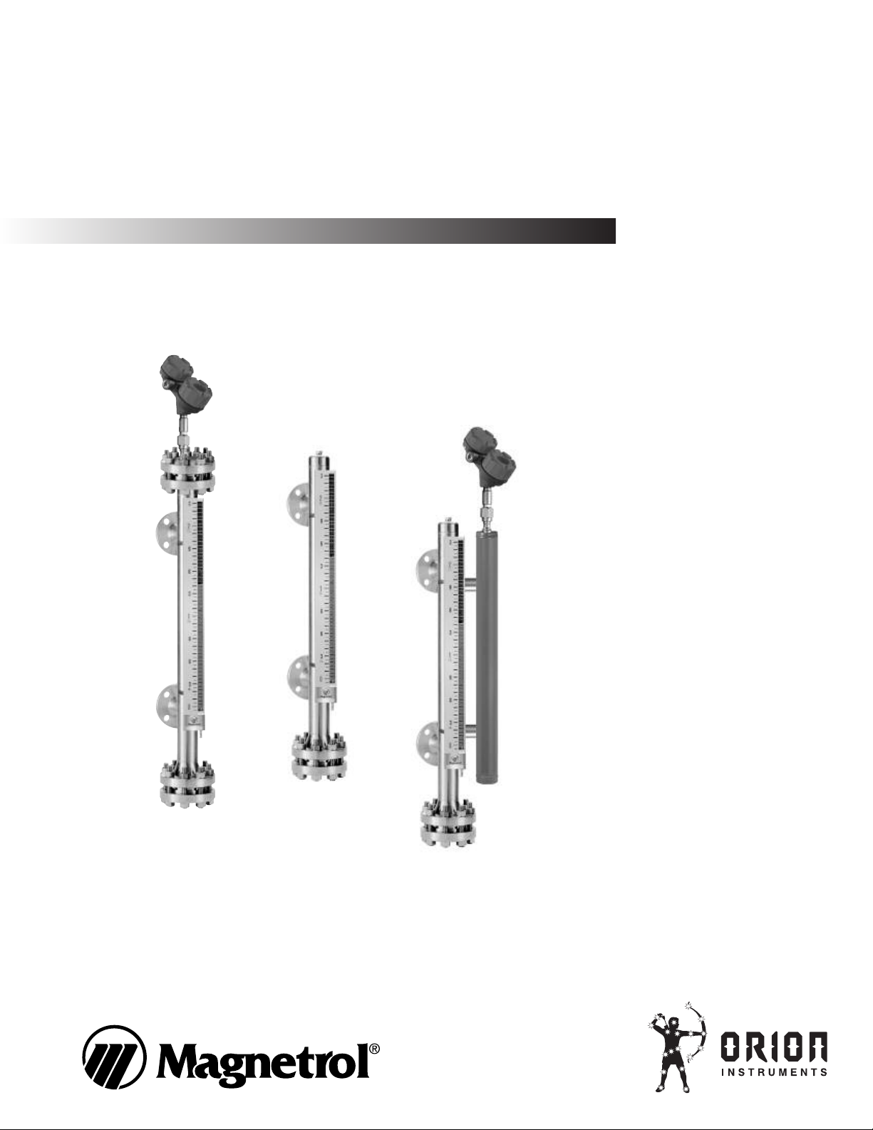
Magnetic Liquid
Level Indicators
Gauges
Switches
Transmitters
A Magnetrol Company
Page 2

Read this Manual Before Installing
his manual provides information on Magnetic Liquid
T
Level Indicators. It is important that all instructions are
read carefully and followed in sequence.
Notice of Trademark, Copyright, and Limitations
agnetrol & Magnetrol logotype, Orion Instruments,
M
Aurora, Eclipse, and Jupiter are trademarks of Magnetrol
International.
Conventions Used in this Manual
Certain conventions are used in this manual to convey
specific types of information. General technical material,
support data, and safety information are presented in
narrative form. The following styles are used for notes,
cautions, and warnings.
Notes
Notes contain information that augments or clarifies
an operating step. Notes do not normally contain
actions. They follow the procedural steps to which
they refer.
Cautions
Cautions alert the technician to special conditions that
could injure personnel, damage equipment, or reduce
a component’s mechanical integrity. Cautions are also
used to alert the technician to unsafe practices or the
need for special protective equipment or specific
materials. In this manual, a caution box indicates a
potentially hazardous situation which, if not avoided,
may result in minor or moderate injury.
Warnings
Warnings identify potentially dangerous situations or
serious hazards. In this manual, a warning indicates an
imminently hazardous situation which, if not avoided,
could result in serious injury or death.
Safety Messages
Follow all standard industry procedures for servicing
electrical equipment when working with or around high
voltage. Always shut off the power supply before touching any components.
WARNING! Explosion hazard. Do not connect or
disconnect equipment unless power has been switched off
or the area is known to be non-hazardous.
Low Voltage Directive
For use in Installation Category II, Pollution Degree 2.
If equipment is used in a manner not specified by the
manufacturer, protection provided by the equipment
may be impaired.
Copyright © 2010 Magnetrol International.
All rights reserved.
Performance specifications are effective with date of issue
and are subject to change without notice. Magnetrol
reserves the right to make changes to the product
described in this manual at any time without notice.
Magnetrol makes no warranty with respect to the accuracy
of the information in this manual.
Warranty
All Magnetrol/Orion mechanical level controls are
warranted free of defects in materials or workmanship for
five full years from the date of original factory shipment.
All Magnetrol/Orion electronic level controls are
warranted free of defects in materials or workmanship for
one full year from the date of original factory shipment.
If returned within the warranty period; and, upon factory
inspection of the control, the cause of the claim is
determined to be covered under the warranty; then,
Magnetrol/Orion will repair or replace the control at no
cost to the purchaser (or owner) other than transportation.
Magnetrol/Orion shall not be liable for misapplication,
labor claims, direct or consequential damage or expense
arising from the installation or use of equipment. There
are no other warranties expressed or implied, except special
written warranties covering some Magnetrol products.
Quality Assurance
The quality assurance system in place at Magnetrol guarantees the highest level of quality throughout the company. Magnetrol is committed to providing full customer
satisfaction both in quality products and quality service.
Magnetrol’s Corporate quality assurance system is registered to ISO 9001
affirming its commitment to known
international quality standards providing the strongest assurance of
product/service quality available.
Page 3

Table of Contents
Magnetic
Liquid Level Indicators
1.0 Installation
1.1 Unpacking.............................................................4
1.2 Pre-installation Checklist .......................................4
1.3 Equipment and Tools ............................................4
1.4 Side Mount Installation.........................................5
1.5 Top Mount Installation .........................................6
1.6 Top/Bottom Connection Installation.....................6
1.7 Start-up .................................................................6
1.8 Special Accessory Installation.................................7
1.8.1 Insulation or Blanket Installation................7
1.8.2 Steam Heat Tracing Installation..................8
1.8.3 Electric Heat Tracing Installation................8
1.8.3.1 Units with a fixed-point
thermostatic switch..............................8
1.8.3.2 Units with an adjustable “bulb-type”
thermostatic switch..............................9
1.9 Switch Installation ...............................................10
1.9.1 OES Cam Operated Switch......................10
1.9.1.1 Mounting to an
Atlas™or Gemini™MLI ....................10
1.9.1.2 Mounting to an Aurora®MLI ...........10
1.9.1.3 Wiring ...............................................11
1.9.2 ORS Electric Reed Switch ........................11
1.9.2.1 Mounting to an
Atlas or Gemini MLI.........................12
1.9.2.2 Mounting to an Aurora MLI .............12
1.9.2.3 Wiring ...............................................12
1.10 Analog Transmitter Installation............................13
1.10.1 OCT Reed Transmitter.............................13
1.11 Internal Electronic Transmitter Installation .........13
1.12 Internal Eclipse®Transmitter Installation.............14
2.0 Reference Information
2.1 Description..........................................................14
2.2 Theory of Operation ...........................................15
2.2.1 Side Mount...............................................15
2.2.2 Top Mount ...............................................15
2.3 Troubleshooting...................................................16
2.3.1 Side Mount...............................................16
2.3.2 Top Mount ...............................................17
2.4 Spare Parts...........................................................17
2.5 Maintenance........................................................17
2.6 Specifications.......................................................18
2.6.1 Magnetic Level Indicator ..........................18
2.6.2 Model OES Switch ...................................19
2.6.3 Model ORS Switch...................................19
2.6.4 Model OCT Analog Transmitter ..............19
2.6.5 Model 2XX Jupiter™ Magnetostrictive
Transmitter ...............................................19
2.6.6 Model 705 Eclipse Transmitter .................19
Page 4

1.0 Installation
Caution: If equipment is used in a manner not specified by manu-
acturer, protection provided by equipment may be
f
impaired.
1.1 Unpacking
Unpack the instrument carefully. Inspect all units for
damage. Report any concealed damage to carrier within
24 hours. Check the contents of the packing slip and
purchase order. Check and record the serial number for
future reference when ordering parts.
Caution: Do not discard the shipping container until all parts are
checked.
1.2 Pre-installation Checklist
1. Manually move the float from 0% to 100% to 0% prior
to start up/check out in order to reinitialize accessory
products, if so equipped. Accessories may inadvertently
change state due to rough handling in shipment.
2. Remove float prior to pressure testing tank.
Caution: Float damage will occur if not removed from chamber prior
to pressure testing the tank.
3. Verify the MLI’s center to center distance equals the
vessel’s center to center.
1.3 Equipment and Tools
• Open-end wrenches or adjustable wrench to fit the process
studs and nuts. A torque wrench is highly desirable.
• Flat-blade screwdriver
• Digital multimeter or digital volt/ammeter if transmitters
or switches are attached
• Level
• Gasket for mating flanges
• Teflon tape & “never seize” for threaded units
• Pipe wrench for threaded units
4
46-638 Magnetic Liquid Level Indicators
Page 5

1.4 Side Mount Installation
Caution: This instrument is intended for use in Installation
ategory II, Pollution Degree 2 locations.
C
NOTE: Top of gauge nameplates are available as an option.
The MLI nameplate can be used as bottom reference of
the external cage. Install the cage to the vessel with nameplate at bottom. Isolation valves are recommended for
installation between vessel and external cage. Check to
ensure the external cage is vertical. All piping should be
straight and free of “low spots” or “pockets” so that the
lower liquid connection will drain toward the external
cage. Adjust piping as required.
It is recommended a drain valve be installed in the bottom
flange to allow cleaning and checking level. Close the
isolation valves until start up.
Initial installation of the Magnetic Level Indicator is simple. Unless otherwise specified, MLIs will be shipped from
the factory fully assembled. All flanges will be torqued to
ANSI specifications. Make sure all process connections
attached to the vessel which the gauge will be mounted to
are vertically level, and flanges, if any are level.
Carefully unpack the MLI and stand it up vertically.
NOTE: Longer units require support of the entire length of the cham-
ber while being lifted in place vertically. This will prevent bowing of the chamber, that could result in glass breakage. Once
the gauge is mounted to the vessel and the liquid level rises
inside the vessel, the gauge will become operational
Isolation valves are recommended, but not required. If
isolation valves are used, care must be used when opening
the valves to prevent a surge of fluid or gases through the
chamber. A surge can cause the float to be propelled to the
far end of the chamber, and float damage could result.
Caution: If for any reason the MLI is pressurized higher than the
maximum pressure indicated on the name tag, the float
inside the chamber is subject to collapsing and causing
float failure.
NOTE: Float is shipped in chamber.
46-638 Magnetic Liquid Level Indicators
5
Page 6

1.5 Top Mount Installation
Caution: This instrument is intended for use in Installation
Category II, Pollution Degree 2 locations.
The top mount gauge can be installed as one complete
unit or disassembled to allow access from inside the tank.
Correct vertical installation is required to assure proper
float movement.
To disassemble you need only to unscrew the threaded cap
at the bottom mounting flange or connection.
Caution: Proper precautions should be taken to prevent the
bending of the guide rod.
1.6 Top/Bottom Connection Installation
Caution: This instrument is intended for use in Installation
Category II, Pollution Degree 2 locations.
Carefully unpack the MLI and stand the unit up vertically.
Note the float stop disc at the bottom flange. Note the
float stop bar (welded in place) at the top of the gauge.
This always indicates the top of gauge.
The float is shipped in the chamber.
Caution: Overall length should be ±1⁄16". Smooth float travel must be
assured by no bending of the chamber pipe.
1.7 Start-up
Increase system pressure slowly while commissioning the
instrument. Thoroughly check for leaks, and verify that
the local indicator device accurately tracks the liquid level.
Verify external accessory devices (switches, transmitter, etc.)
are functional and properly calibrated.
Caution: Do not open the bottom isolation valve quickly. Allow the
level to rise until the MLI displays the correct level in the
vessel.
6
46-638 Magnetic Liquid Level Indicators
Page 7

1.8 Special Accessory Installation
1.8.1 Insulation or Blanket Installation
Factory recommended high temperature insulation specifications:
Temperature Thickness Liner Jacket
0° to +250° F (-18° to +121° C)
+251° to +500° F (+122° to +260° C) 1" Weather resistant silicone cloth
+501° to +1000° F (+261° to +538° C) 2" Weather resistant aluminized silicone cloth
1
⁄2"
Weather resistant silicone cloth
• Thickness is1⁄2" when the MLI has switches or a transmitter.
• Insulation used is 8 lb. density ceramic blanket
• All removable insulated blankets are fastened to the MLI by
velcro and straps. Quilting pins available as an option.
• All removable insulation blankets are sewn with fire retardant
teflon thread.
• High temperature guide for the level flow gauge side mount:
Consult factory for specific temperature guide lines.
Figure 1
Low Temperature
Insulated Magnetic
Level Indicator
Factory recommended cryogenic insulation specifications:
Temperature Thickness Liner Jacket
+32° to -100° F (0° to -73° C) 2"
-101° to -320° F (-74° to -196° C) 4"
Outdoor .016 smooth aluminum Polyurethane with all
jacket with vapor barrier service jacket vapor barrier
• Purpose: To maintain the required low temperature of the
service fluid to be measured.
• All insulation joints will be staggered.
• All insulation joints will be sealed with a non-breathing
moisture resistant mastic.
• All weather resisting jacketing seams will be sealed with a
weather resistant caulk.
• The weather resistant jacket will be sealed to the 2" or 4"
plexiglass frost extension, with weather resistant caulk.
• The face of the frost extension must always be exposed.
• Cryogenic units will be flipper style indicators.
46-638 Magnetic Liquid Level Indicators
7
Page 8

Figure 2
1.8.2 Steam Heat Tracing Installation
Steam Heat Tracing is available as a factory installed
option. Steam traced units are generally supplied with a
factory installed insulation blanket (also optional).
3
Two steam connections (typically
⁄8" × 0.035" tubing)
protrude from the unit. See Figure 2. The following
installation procedure is suggested:
• Remove factory installed plastic caps from the tube ends.
• Inspect tube ends for dents and burrs. Tubing length may
be adjusted (cut), if required.
• Compressed air may be applied to either end to verify that
no foreign material exists in the tube tracing assembly.
• A suitable saturated steam source and drain should be connected. Do not exceed applicable pressure ratings for the
particular tubing size. Standard compression fittings may
be used to make the connections, and either connection
may be used as inlet or outlet.
• Apply steam to the unit and check for leaks.
Figure 3
• Contact factory or local representative for assistance, if
required.
1.8.3 Electric Heat Tracing Installation
Electric Heat Tracing is available as a factory installed
option. Electric traced units are generally supplied with a
factory installed insulation blanket (also optional).
Electrical connections are supplied, based on specific
customer requirements. Operating voltage and power
consumption will vary for each particular configuration.
More specific information is supplied with each unit,
and is also available from the factory (unit serial number
is required).
The two most common configurations are units with a
fixed-point thermostatic switch or units with an adjustable
“bulb-type” thermostatic switch.
1.8.3.1 Units with a fixed-point thermostatic switch
With a fixed-point thermostatic switch (customer specified
temperature set point), a wiring harness, or optional
junction box with terminal strip will be available to
accommodate field wiring. See Figure 3 (typical).
NOTE: It is the responsibility of the customer to comply with applica-
ble installation codes and practices. Installation should be
performed by qualified personnel.
8
46-638 Magnetic Liquid Level Indicators
Page 9

1. Locate specific power specification and wiring diagram
supplied with unit.
2. Provide appropriate conduit and wiring to the unit.
3. Apply sufficient operating power.
4. Verify that unit will generate sufficient heat and maintain
proper temperature.
NOTE: Wiring diagrams are supplied with units manufactured with
this option.
1.8.3.2 Units with an adjustable “bulb-type” thermostatic switch
With an adjustable “bulb-type” thermostatic switch, the
temperature may be preset at the factory, however field
personnel should verify this setting during installation. A
wiring harness, or optional junction box with terminal
strip will be available to accommodate field wiring.
NOTE: For supply connections, use wire with a minimum rating of
+167° F (+75° C) as required by process conditions. Use a
minimum of 14 AWG wire for power and ground field wires.
NOTE: Housing must be grounded via protective ground screw in the
base of the housing.
NOTE: It is the responsibility of the customer to comply with applica-
ble installation codes and practices. Class I, Division 1 locations may contain explosive gas mixtures. Appropriate
precautions must be taken. Installation should be performed
by qualified personnel.
1. Locate specific power specification and wiring diagram
supplied with unit.
2. Provide appropriate conduit and wiring to the unit.
3. Verify thermostat setting. Adjust, if necessary.
4. Apply sufficient operating power. Circuit breaker should
be a GFI (ground fault interrupter) type with maximum
30 mA ground leakage current trip setting. GFI should
be sized at 125% of rated load.
5. Verify that unit will generate sufficient heat and maintain
proper temperature.
NOTE: Wiring diagrams are supplied with units manufactured with
this option.
46-638 Magnetic Liquid Level Indicators
Caution: In hazardous areas, do not power the unit until the conduit
is sealed and the enclosure cover is screwed down securely.
9
Page 10

3.0 (76)
REF.
5.5 (139)
REF.
8.375 (212)
REF.
(2) 3/4" NPT
conduit connections
.5 (12)
REF.
INSTALL
THIS SIDE
UP
ORION INSTRUMENTS
FLOAT BELOW SWITCH
inches (mm)
1.9 Switch Installation
1.9.1 OES Cam Operated Switch
The Model OES snap switch is utilized to expand the control capabilities of Orion’s extensive line of magnetic level
indicators. This cam-operated double pole double throw
mechanism is clamp-mounted to the outside of the MLI.
This mounting style allows easy addition or repositioning
of switches without disruption of the process.
The OES switch(es) are pre-installed, calibrated, and
checked for proper orientation at the factory. Your unit
may be equipped with one or more switches for alarming
or control. To change the location of the switch in the
field, simply unscrew the clamp and slide the switch to a
new location. See Figure 4.
1.9.1.1 Mounting to an Atlas™or Gemini™MLI
Caution: If equipment is used in a manner not specified by the
manufacturer, protection provided by the equipment may
be impaired.
Figure 4
Contact closure is shown with the
magnetic float below the switch
Figure 5
Wiring of OES
cam operated switch
Remove the cover of the enclosure. Position the OES camoperated snap switch on the MLI body so that the centerline of the switch enclosure is at the desired switch point
level. Ensure that the switch is oriented so that the arrow
on the switch mechanism is pointing toward the top of the
MLI. Install the clamps around the MLI and over the
mounting brackets on the top and bottom of the switch
housing. Tighten the clamps so that the switch is secured
to the MLI. Replace housing cover. If required, place the
insulation between the MLI body and the switch before
tightening the clamps.
1.9.1.2 Mounting to an Aurora®MLI
The Aurora may be ordered with one or more OES clampon switches. During assembly Orion can ensure proper
function of the switches. Special care must be taken when
adding OES switches to an Aurora after initial purchase.
For proper function, the switch must be located as close to
the internal float magnet as possible. This is achieved by
marking the location of the indicator on the Aurora body.
The indicator must be rotated on the chamber so that the
switch can be positioned closest to the float. Loosen the
indicator clamps, rotate the indicator 90 degrees around the
chamber and retighten the clamps. Mount the OES switch
where the indicator was originally located. Move the float,
or move level, to verify proper operation of the switch.
10
46-638 Magnetic Liquid Level Indicators
Page 11

1.9.1.3 Wiring
The lower conduit opening is protected with a plastic
shipping plug. The upper opening is sealed with a steel
plug. If it is preferable to wire through the upper conduit
entry, the steel plug may be moved to the lower opening.
NOTE: For supply connections, use wire with a minimum rating of
+167˚ F (+75˚ C) as required by the process conditions. Use a
minimum of 14 AWG wire for power and ground field wires.
NOTE: Housing must be grounded via protective ground screw in
base of housing.
Caution: In hazardous areas, do not power the unit until the conduit
is sealed and the enclosure is screwed down securely.
The DPDT switch has two sets of contacts. See Figure 5
on page 7 and label on mechanism. To wire switch, strip
about
1
⁄2" of insulation from end of wire. Using a flat head
screwdriver or pliers, push orange tab away from the wire
opening on the terminal block. DO NOT pry up on the
orange tab as damage to the terminal block may result.
Insert wire into opening and release tab. Check that the
wire is securely fastened within the terminal block. Repeat
for balance of connections.
1.9.2 ORS Electric Reed Switch
The Model ORS reed switch is available to augment the
control capabilities of Orion’s extensive line of magnetic
level indicators. Housed in an explosion proof stainless
steel enclosure, the ORS mounts to the outside of the
MLI via clamps. This mounting style allows addition or
repositioning of switches at any time, without disruption
of the process.
The ORS switch(es) are pre-installed, calibrated, and
checked for proper orientation at the factory. Your unit
may be equipped with one or more switches for alarming
or control. To change the location of the switch in the
field, simply unscrew the clamp and slide the switch to a
new location.
46-638 Magnetic Liquid Level Indicators
11
Page 12

FLOAT ABOVE SWITCH
FLOAT BELOW SWITCH
1 (RED)
C
(WHITE)
C (WHITE)
2 (BLACK)
1 (RED)
2 (BLACK)
8-32 Ground Screw
3.00
(76.2)
3.00
(76.2)
1/2"
MNPT
1.00
(25.4)
0.84
(21.3)
inches (mm)
1.9.2.1 Mounting to an Atlas or Gemini MLI
aution: If equipment is used in a manner not specified by the
C
manufacturer, protection provided by the equipment may
be impaired.
With mounting clamps loosened, position ORS reed
switch on the MLI body so that the centerline of the stainless steel tube which houses the switch is at the desired
switch point level. The switch should be oriented so that
the green ground screw is closest to the top of the MLI.
See Figure 8. Tighten the clamps so that the switch is
secured to the MLI. If required, place the insulation
between the MLI body and the switch before tightening
the clamps.
Figure 8
Figure 9
Wiring of ORS
Reed Switch
Contact closure shown for
both conditions of the switch
relative to the magnetic float
1.9.2.2 Mounting to an Aurora MLI
Follow procedure for mounting to Atlas or Gemini, but
ensure that the switch is positioned on the circumference
of the Aurora body as close to the indicator as possible.
1.9.2.3 Wiring
The leads protruding from the potted end of the switch
housing are color coded as follows:
White = Common
Black = Normally Closed
Red = Normally Open
NOTE: For supply connections, use wire with a minimum rating of
+167° F (+75° C) as required by the process conditions. Use a
minimum of 14 AWG wire for power and ground field wires.
NOTE: Housing must be grounded via protective ground screw on
upper mounting tab.
12
46-638 Magnetic Liquid Level Indicators
Page 13

4.0 (102) REF.
Inactive length
XXX = Span
active length
3.8 (140)
REF.
3.5 (90)
REF.
4.5 (115)
REF.
0.4 (10) REF.
Label bracket
3/4" NPT
conduit
connection
red
yellow
black
Resistor
Chain
Reed
Switch
inches (mm)
Figure 10
1.10 Analog Transmitter Installation
1.10.1 OCT Reed Transmitter
The OCT analog transmitter mounts directly to the side
of the Atlas or Gemini chamber, providing a continuous
4–20 mA output signal proportional to liquid level. Using
simple and reliable reed switches surface mounted to a
printed circuit board, the unit provides level accuracy of
±0.50" (13 mm).
The OCT reed transmitter is shipped attached to the MLI
gauge and is precalibrated to the customer specified span.
See Figure 10. Refer to Figure 11 for wire terminations for
the OCT.
Installation is simplified by utilizing gear clamps that can
be repositioned with a screw driver.
Caution: If the MLI is insulated, the analog transmitter probe must be
located outside of the insulation blanket.
NOTE: For supply connections, use wire with a minimum rating of
+167° F (+75° C) as required by process conditions. Use a
minimum of 14 AWG wire for power and ground field wires.
black: common connection of reed contacts
yellow: upper end of the resistor chain
red: lower end of the resistor chain
46-638 Magnetic Liquid Level Indicators
Figure 11
NOTE: Housing must be grounded via protective ground screw in the
base of the housing.
NOTE: It is the responsibility of the customer to comply with applicable
installation codes and practices. Class I, Division 1 locations
may contain explosive gas mixtures. Appropriate precautions
must be taken. Installation should be performed by qualified
personnel.
Caution: In hazardous areas, do not power the unit until the conduit
is sealed and the enclosure cover is screwed down securely.
1.11 Internal Electronic Transmitter Installation
The Gemini Model enables the customer to install several
different types of either continuous measuring instruments
(transmitters) or point level control devices (switches). The
electronic instrument is installed in the 2" or 3" secondary
chamber of the Gemini MLI. The factory should be consulted for these applications to review operating parameters
and to ensure that the desired instrument is properly
applied.
As the electronic instrument is supplied separately from
the Gemini MLI, the instruction manual for the electronic
unit should be carefully reviewed prior to installation in
the chamber. The instruction manual will be shipped with
the instrument.
13
Page 14

1.12 Internal Eclipse Transmitter Installation
The Eclipse Guided Wave Radar Transmitter can be
mounted in either the Gemini or the Aurora MLIs. The
Aurora is designed to support operation of the Eclipse in
the same chamber as the float. Due to this, the coaxial
type probe must be used. With the dual chamber Gemini
design, either the twin rod, coaxial, or single rod types
may be used. Caution should be exercised in probe selection to take into account, media dielectric, viscosity, temperature, pressure, transition zone distances and overfill
requirements. Each Eclipse will be supplied complete with
an instruction manual. A review of the manual is recommended prior to installation of the Eclipse transmitter in
the Gemini or Aurora MLI.
NOTE: Flag or shuttle indicator can be designed for mounting at any
angle. Do not rotate indicator after gauge is manufactured,
due to inability to rotate baffle plate once welding has been
completed.
2.0 Reference Information
2.1 Description
Magnetic Level Indicators (MLIs) are suitable for installation on process applications that will not restrict float travel
in the piping column. It is a magnetic coupled, local level
indicator which is isolated from the process in a sealed
non-magnetic external cage. Bi-color flags provide visual
indication of level up to 100 feet. Field-adjustable level
switches and transmitters are available as options.
The Atlas is a magnetically coupled local level indicator
isolated from the process via a sealed non-magnetic external chamber. A fluorescent orange shuttle or series of bicolored flags provide visual indication of liquid level from
distances of up to 100 feet. Available switches for point
alarms include electronic DPDT, reed and pneumatic
technologies. Transmitter technologies for continuous
4–20 mA outputs include reed and guided wave radar.
Atlas is suitable for installation on process applications
including corrosive services that do not impede the movement of the float in the piping column.
14
Aurora and Gemini incorporate a combination of the
Atlas magnetic level gauge and Magnetrol’s Eclipse
Guided Wave Radar. This represents the industries first
totally redundant mag gauge/transmitter combination.
46-638 Magnetic Liquid Level Indicators
Page 15

Local indication, 4–20 mA output, HART and Fieldbus
Stainless steel
chamber wall
Float
magnets
Liquid
level
Float
Flux ring
Indicating
flags
Flux
ring
Magnet
spacer
protocols are available. Float damage will not result in loss
of the 4–20 mA signal
Aurora: The Eclipse Guided Wave Radar probe is mounted directly inside of the Gemini chamber. a minimum
3" chamber is utilized to accommodate the Eclipse probe
and allow unobstructed float travel. Patent pending.
Gemini: The dual chamber approach also accomplishes
total redundancy but increases the ease of gauge or transmitter isolation. The Atlas gauge provides local indication
while the Eclipse is mounted directly inside a connected
second chamber. The units perform independently of
each other.
2.2 Theory of Operation
2.2.1 Side Mount
A float equipped with a strong magnet assembly inside and
weighted to the specific gravity of the fluid to be measured,
moves up and down in a non-magnetic chamber, as the
fluid inside rises and falls with the level of the liquid in
the vessel.
Figure 12
Figure 13
Attached to the external wall of the non-magnetic chamber
is a non-porous glass tube. Inside this hermetically sealed
glass tube is a highly visible fluorescent orange indicator or
flags with a strong magnetic assembly inside. See Figures
12 and 13.
The indicator is always coupled to the float magnetically,
to indicate the exact measurement of the fluid.
2.2.2 Top Mount
A top mounted float assembly consisting of a magnet
assembly at the top, a guide rod in the middle, and a float
at the bottom. The float at the bottom is submerged in the
liquid inside the vessel. The entire guide rod assembly is
weighted to the specific gravity of the fluid to be measured.
Attached to the external wall of the non-magnetic chamber
is a non-porous glass tube. Inside this hermetically sealed
glass tube is a highly visible fluorescent orange indicator or
flags with a strong magnetic assembly inside. See Figures
12 and 13.
The indicator or flags are always coupled to the magnetic
assembly, to indicate the exact measurement of the fluid.
46-638 Magnetic Liquid Level Indicators
15
Page 16

2.3 Troubleshooting
2.3.1 Side Mount
Problem Solution
Flags do not rotate with level change. Test flags with a magnet from bottom to top (magnet not
ncluded). If flags test okay, check for float obstruction.
i
(See Section 2.5, Maintenance on page 16)
Flags rotate at different height than actual level. Float selected for different specific gravity. Replace float with
a float with correct specific gravity rating. Confirm correctness
of float orientation. Top is up.
Float inside the level gauge is moving Make sure the MLI is level vertically.
slow or not at all.
The process fluid being measured may be too viscous and
heat tracing may be required to make the material more fluid.
Heat tracing can be purchased from the factory.
The specific gravity of the process fluid and the float weight
may need to be reverified.
The liquid being measured may contain magnetic particles
collecting on the magnetic section of the float causing drag.
If this happens, magnetic trap assemblies can be purchased
from the factory.
Visual inspection of the float may be required to see if the float
has collapsed.
Switch does not actuate with level change. Check micro switch for continuity. Replace if damaged. If
okay, remove switch from piping column and test switch magnet assembly with re-alignment magnet, by moving magnet
over the housing face. If the switch magnet assembly fails to
respond, replace the switch. If the switch tests okay, check
float travel.
Reed transmitter does not track level. Remove transmitter assembly from piping column and test
with re-alignment magnet. Run magnet from bottom to top of
reed chain. Check zero and span calibration. If no change in
output, replace.
Scale is at zero to the center of the bottom The scale assembly is mounted to the chamber using stainless
process connection, but the indicator is above steel gear clamps. It can be easily adjusted in the field using a
or below zero. screwdriver. Make sure the scale zero is in line with the center
of the process connection.
The float stop spring at each end of the chamber is there to
cushion as well as position the float assembly to the center of
the process connection. Make sure top or bottom float stop
springs are not bent or broken.
Shuttle indicator has uncoupled and In some “flashing” applications, the float may rise or fall quickly.
fallen to the bottom of the glass tube. Consult factory for suggestions to help avoid this.
To re-couple the indicator to the float, simply use a small magnet and run it along the length of the chamber to locate the
float. Mark the location of the float on the outside chamber.
Use the small magnet to couple with the indicator and pull the
indicator up to meet and couple with the float.
16
Make sure all stainless steel gear clamps are tight. The scale
channel must be tight against the chamber.
NOTE: Ensure unit installation is level.
46-638 Magnetic Liquid Level Indicators
Page 17

2.3.2 Top Mount
Problem Solution
The float assembly or visual indicator is Make sure the vessel opening or flange connection that the to
moving slowly or not at all. mount flange connects to is level.
he top mount guide rod assembly may be bent. Visual inspec-
T
tion is required.
The process fluid in the vessel may be too viscous, Heating the
vessel to make the process fluid more liquid may be required.
The specific gravity of the process fluid and the float may need
to be reverified.
Visual inspection of the float inside the process fluid may be
required to see if the float has collapsed.
My scale is at the center of the zero mark on The scale assembly is mounted to the chamber using stainless
the outside of the top mount chamber but steel gear clamps. It can be easily adjusted in the field using a
the indicator is above or below zero. screwdriver. Make sure the scale zero is in line with the zero
mark on the outside of the top mount chamber.
The float stop spring at the top of the chamber is there to cushion the magnet assembly. Make sure the bottom float stop tube
is not bent or broken
The float stop tube is at the bottom inside the chamber. It is
there to stop the magnet assembly at the zero mark on the outside of the chamber
2.4 Spare Parts
Spare parts are available for Magnetrol/Orion MLIs and
certain switches and transmitters. Please consult the factory.
Have the unit model number and serial number available
for reference.
2.5 Maintenance
Periodic inspections are a necessary means to keep your
level control in good working order. This control is a safety
device to protect the valuable equipment it serves.
If the process liquid is clean (no solids or deposits), the
MLI should require minimum maintenance. If the process
liquid is dirty (solids and deposits), it is recommended the
external cage be isolated from the process and flushed periodically. For complete cleaning, after draining the unit,
remove the bottom flange and float, inspect cage and float
for buildup and clean if required.
46-638 Magnetic Liquid Level Indicators
Magnetic traps are available to prevent magnetic particulate travel from the vessel to the chamber.
17
Page 18

2.6 Specifications
2.6.1 Magnetic Level Indicator
Design Atlas and Aurora – single chamber
Gemini – dual chamber
Materials of construction – MLI Metal alloys 316/316L or 304/304L stainless steel,
321 stainless steel, 347 stainless steel,
Titanium, Monel, Hastelloy B,
Hastelloy C-276, Inconel 625, Inconel 825,
Alloy 20, Electropolished 316 stainless steel,
904L stainless steel and other non-magnetic alloys
Plastics Fiberglass, PVC, CPVC, kynar, polypropylene
Materials of construction – Float Same as chamber materials, 316 SS or titanium standard
Construction options Conformance to ASME B31.1, ASME B31.3 or NACE MR0175
available
Certified material test reports (CMTR) Available upon request
Pressure class ratings ANSI 150#, 300#, 600#, 900#, 1500#, 2500#
DIN PN16, PN25/40, PN64, PN100, PN160, PN250, PN320
Process connection sizes
Process connection types MNPT, FNPT, weldolet®, sockolet®, threaded couplings,
Measuring range 12 to 600 inch (30 to 1524 centimeters) standard
Temperature range -320° to +1000° F (-196° to +538° C)
Pressure range Full vacuum to 4500 psig (310 bar)
Specific gravity range As low as 0.35 S.G.U.
Indicators Magnetically actuated flag assembly in contrasting orange/black,
Flag assembly seal Inert gas filled and hermetically sealed with Insta-seal valve
Visual indication Easily visible from 75 to 100 feet (23 to 30 meters)
Scale options Etched stainless steel with either height, volume, or
Switch options Model OES electric cam operated snap action
Transmitter options Model 705 Eclipse Guided Wave Radar
High temperature options Electric or steam tracing with or without special high
Low temperature options Cryogenic insulation with special polymeric frost extension
1
⁄2" to 8"
DN 20 to DN 150
threaded nipples, buttweld nipples, plain-end nipples,
slip-on flanges, weldneck flanges, lap joint flanges,
tri-clamp fitting, Van Stone flanges
Consult factory for lengths over 600 inch (50 feet)
yellow/black, red/white colors, or high visibility shuttle follower
percentage units
Model ORS electric reed type
Model 2xx Jupiter Magnetostrictive
Model OCT analog reed chain
temperature insulation
18
46-638 Magnetic Liquid Level Indicators
Page 19

2.6.2 Model OES Switch
• Electric snap action switch
• 10 amp DPDT
• ±0.75" (19 mm) float travel
• -58° to +392° F (-50° to +200° C)
• Cast aluminum enclosure, (2)1⁄2" NPT conduit entries
See bulletin OES for further information
2.6.3 Model ORS Switch
• Electric reed switch, hermetically sealed
• 1 amp SPDT
• Stainless steel enclosure with mounting tabs
• ±0.5" (13 mm) float travel
• -58° to +482° F (-50° to +250° C)
• Stainless steel enclosure with mounting tabs
See bulletin ORS for further information
2.6.4 Model OCT Analog Transmitter
Power: 24 VDC
Maximum Range: Up to 20 feet standard
(Consult factory for longer lengths)
Accuracy: ±0.5" (13 mm)
Output: 4–20 mA
Temperature range: -40° to +500° F (-40° to +260°C)
See bulletin OCT for further information
2.6.5 Model 2XX Jupiter™Magnetostrictive Transmitter
Power: 24 VDC
Maximum Range: Up to 35 feet (10.67 meters)
Accuracy: ±0.015" (0.38 mm)
Output: 4–20 mA (HART optional)
Temperature range: -40° to +175° F (-40° to +79°C)
See bulletin ORI-148 for further information
2.6.6 Model 705 Eclipse Transmitter
See bulletin 57-101 for details
46-638 Magnetic Liquid Level Indicators
19
Page 20

ASSURED QUALITY & SERVICE COST LESS
5300 B elmont Roa d • D owners Grov e, Il linois 605 15-4499 • 6 30-969 -4000 • F ax 630 -969-9489 • www.ma gnetro l.com
145 Ja rdin Dr ive, Unit s 1 & 2 • Conc ord, O ntario Can ada L 4K 1X7 • 9 05-738-9600 • F ax 905-738- 1306
Heiken sstraa t 6 • B 9 240 Ze le, Belgium • 0 52 45. 11.11 • F ax 052 45. 09.93
Regent Bus iness Ctr., Ju bilee Rd. • Bu rgess Hil l, Sus sex RH15 9T L U.K. • 01444-8713 13 • F ax 01 444-87 1317
6646 C omplex Dri ve • Bato n Roug e, Louisian a 7080 9 • 2 25-906 -2343 • Fax 225 -906-2 344 • www.or ioninstrume nts.co m
Copyright © 2010 Magnetrol International, Incorporated. All rights reserved. Printed in the USA.
Service Policy
Owners of Magnetrol/Orion Instruments controls may
request the return of a or any part of an instrument for
complete rebuilding or replacement. They will be rebuilt
or replaced promptly. Instruments returned under our
service policy must be returned by prepaid transportation. Magnetrol will repair or replace the control at no
cost to the purchaser (or owner) other than transportation if:
1. Returned within the warranty period; and
2. The factory inspection finds the cause of the claim
to be covered under the warranty.
If the trouble is the result of conditions beyond our
control; or, is NOT covered by the warranty, there will
be charges for labor and the parts required to rebuild or
replace the equipment.
In some cases it may be expedient to ship replacement
parts; or, in extreme cases a complete new instrument,
to replace the original equipment before it is returned. If
this is desired, notify the factory of both the model and
serial numbers of the instrument to be replaced. In such
cases, credit for the materials returned will be determined on the basis of the applicability of our warranty.
Return Material Procedure
So that we may efficiently process any materials that are
returned, it is essential that a “Return Material
Authorization” (RMA) number be obtained from the
factory, prior to the material's return. This is available
through Magnetrol’s local representative or by contacting the factory. Please supply the following information:
1. Company Name
2. Description of Material
3. Serial Number
4. Reason for Return
5. Application
Any unit that was used in a process must be properly
cleaned in accordance with OSHA standards, before it is
returned to the factory.
A Material Safety Data Sheet (MSDS) must accompany
material that was used in any media.
All shipments returned to the factory must be by prepaid transportation.
All replacements will be shipped F.O.B. factory.
No claims for misapplication, labor, direct or consequential damage will be allowed.
Viton® is a registered trademark of DuPont Performance Elastomers.
BULLETIN: 46-638.5
EFFECTIVE: August 2010
SUPERSEDES: August 2004
 Loading...