

Page 1
IN 104 Rev.B 0199
Providing Exceptional Consumer Optical Products Since 1975
Customer Support (800) 676-1343
E-mail: support@telescope.com
Corporate Offices (831) 763-7000
P.O. Box 1815, Santa Cruz, CA 95061
INSTRUCTION MANUAL
Orion
®
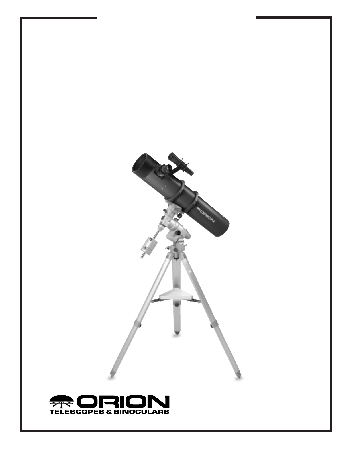
Argonaut
™
6"
Maksutov-Newtonian
#9068 Optical Tube Assembly
#21481 With GP-DX Equatorial Mount
Page 2

2
1. Parts List
Qty. Description
1 Optical tube assembly
1 10x50 finder scope
1 Finder scope bracket
2 Tube mounting rings
1 Standard mounting plate
1 Dust cover
If you purchased the #21481 package, the following items
should also be included (in one or more additional boxes):
1 GP-DX equatorial mount
1 Aluminum tripod
1 Dovetail mounting plate
1 Extra 8.1-lb. counterweight
2 6mmx1 socket head cap screws
2. Unpacking and Assembly
Exercise care when unpacking the shipping box(es). We recommend keeping the original shipping box and packing
materials; in the event the telescope needs to be shipped to
another location or returned to Orion for warranty repair, having the proper shipping container will help ensure that your
telescope will survive the journey intact.
The only assembly required for the Argonaut 6" optical tube is
to attach the finder scope bracket (the finder scope comes
already installed in the bracket. Locate the mounting block
adjacent to the telescope’s focuser. Line up the tab on the bottom of the finder bracket base with the slot on the mounting
block. Thread the thumbscrew on the base of the bracket into
the threaded hole on the mounting block until tight. Make sure
the finder scope is positioned in the bracket so the wide (objective) end points toward the front of the telescope; you may have
to remove the finder scope from the bracket and turn it around.
Do so by first loosening all the nylon adjustment screws.
If you have purchased the package with the GP-DX mount,
refer to the instructions that come with the mount in order to
assemble it. Before the telescope can be attached to the GPDX mount, the optical tube will need to be connected to the
dovetail mounting plate. First, remove the standard mounting
plate that is already attached to the tube rings. Use a 5mm
Allen wrench to unthread the four socket head cap screws.
Locate the two 6mmx1 socket head cap screws that are
included with the package. These are not the screws that
come taped to the dovetail mounting plate; those screws
have no purpose here, and may be discarded. Attach the
dovetail mounting plate to the tube rings with the 6mmx1
screws. Of the three holes on the bottom of each tube mounting ring, use the one that is in the center. You will need to
position the tube rings slightly closer to each other in order to
achieve the hole spacing on the dovetail bracket. This is done
by loosening the tube ring lock knob on the side of the ring,
C
ongratulations on purchasing an Orion telescope!
The Argonaut 6" Maksutov-Newtonian is a precision instrument designed for high-performance astronomical observation. With its Maksutov-Newtonian
optical system expertly crafted in Russia, you’ll enjoy exquisite views of countless celestial objects.
These instructions will help you properly use and care for your telescope. Please read them over thoroughly before getting started.
Table of Contents
1. Parts List................................................................................................................................. 3
2. Unpacking and Assembly....................................................................................................... 3
3. The Optics .............................................................................................................................. 4
4. Using the Telescope ............................................................................................................... 5
5. Care and Maintenance........................................................................................................... 6
6. Specifications.......................................................................................................................... 6
7. Suggested Accessories.......................................................................................................... 6
WARNING:
Never look directly at the
Sun through your telescope or its finder
scope—even for an instant—without
a professionally made solar filter that
completely covers the front of the
instrument, or permanent eye damage
could result. Be sure to also cover the
front of the finder scope with aluminum
foil or another opaque material to prevent
physical damage to the internal
components of the scope itself as well as to
your eye. Young children should use this
telescope only with adult supervision.
Page 3

3
and then moving the ring down the telescope optical tube
until properly positioned. Retighten the tube ring lock knob
when done. Attach the dovetail mounting plate so that the
smooth, flat side of it faces the telescope optical tube.
Now that the dovetail mounting plate is attached to the tube
rings, the optical tube fits into the dovetail slot on the head of
the GP-DX mount. Make sure both included counterweights
are placed on the counterweight shaft; both weights are necessary to properly balance the load. Secure the optical tube
in place with the dovetail tube plate lock screw. Also tighten
the knurled metal safety screw. Refer to the manual that
comes with the GP-DX mount for instructions on how to balance and properly use the mount.
3. The Optics
The Maksutov-Newtonian optical design yields exquisite,
refractor-like images yet has a much more compact optical
tube than an equivalent 6" refractor. It employs a spherical
primary mirror. A spherical mirror of this aperture would, by
itself, yield an unacceptable degree of spherical aberration,
so the design incorporates a deeply concave “corrector” lens,
often called a “meniscus,” at the front of the scope. This lens,
at the center of which the secondary mirror holder is mounted, provides sufficient correction to render a sharp,
undistorted image. The diameter of the central obstruction
has also been minimized to further increase image contrast.
The purplish tint of the meniscus is caused by multi-layer
coatings that have been applied to the surfaces of the glass
to enhance light transmission and image contrast.
Collimation
Collimation is the process of adjusting the optical components of a telescope so they are perfectly aligned with each
other. Your telescope’s optics were aligned at the
factory, and should not need much adjustment unless the
telescope was roughly handled during shipment. You will
never need to adjust the positioning of the front corrector
lens; only the primary and secondary mirrors. Accurate alignment is important to insure the peak performance of your
telescope, so it should be checked occasionally. Collimation
of the mirrors is easy to do and should be done in daylight.
To check the collimation, remove the eyepiece and look
straight down the focuser drawtube. Turn the focus knob until
the drawtube is in its most recessed position, and hold your
eye just above the end of the drawtube. Make sure you are
looking straight down the focuser, or your adjustments will not
be correct. You should see the secondary mirror centered in
the drawtube, the reflection of the primary mirror centered in
the secondary mirror, and the reflection of the secondary mirror centered in the reflection of the primary mirror (behind the
reflection of the primary mirror’s central black circle), as in
Figure 1D, page 7. If anything is off-center, follow the
collimation procedure below.
Use a Collimation Tool
To aid in centering your line of sight down the focuser drawtube, and in centering the mirror reflections during collimation,
it is very helpful to use a precision collimating tool containing
crosshairs, such as the Orion Collimating Eyepiece #3640.
We highly recommend you purchase one.
Aligning the Secondary Mirror
With the eyepiece removed, look straight down the open
focuser drawtube at the secondary (diagonal) mirror. It helps
to adjust the secondary mirror in a brightly lit room with the
telescope pointed toward a bright surface, such as white
paper or a wall. Ignoring the reflections, the secondary mirror
itself should be centered in the field of view. If it isn’t, it must
be returned to Orion Telescopes to be adjusted, as this cannot be corrected by the user. This has been checked during
assembly at the factory, so there should not be a problem.
If the entire primary mirror reflection is not visible in the secondary mirror (as it is not in Figure 1B), you will need to adjust
the tilt of the secondary mirror. This is done by alternately
loosening one of the three alignment screws visible in the
center of the corrector lens a turn or two and tightening another one. You will need a flat-head screwdriver to do this. (Do
not adjust the central Phillips-head screw!) The goal is to center the primary mirror reflection in the secondary mirror, as
depicted in Figure 1C. Don’t worry that the reflection of the
secondary mirror (the smallest circle, with your eye reflected
in it) is off-center behind the reflection of the primary’s central
black circle (as also is the case in Figure 1C); you will fix that
in the next step.
Adjusting the Primary Mirror
The final adjustment is made to the primary mirror. It will need
adjustment if, as in Figure 1C, the secondary mirror is centered under the focuser and the reflection of the primary
mirror is centered in the secondary mirror, but the small
reflection of the secondary mirror (with your eye inside) is offcenter behind the reflection of the black circle in the center of
the primary. The tilt of the primary mirror is adjusted with the
three sets of collimation screws on the back end of the optical tube (bottom of the mirror cell). The collimation screws
can be turned with Allen-head wrenches.
Each set of collimation screws works together to adjust the
tilt. The smaller screw pushes the mirror cell forward, while
the larger screw pulls the mirror cell back. One must be loosened and the other tightened by the same amount to adjust
the tilt. Try tightening and loosening one set of collimation
screws one turn. Look into the focuser and see if the secondary mirror reflection has moved closer to the center of the
primary mirror reflection. Repeat this process on the other
two sets of collimation screws, if necessary. It will take a little
trial and error to get a feel for how to tilt the mirror in this way
to center the reflection. (It helps to have two people for primary mirror collimation, one to look in the focuser while the
other adjusts the collimation screws.)
The view through the Collimating Eyepiece should now
resemble Figure 1D. The secondary mirror is centered in the
focuser; the reflection of the primary mirror is centered in the
Page 4

4
secondary mirror, and the reflection of the secondary mirror is
centered in the reflection of the primary mirror (behind the
central black circle).
A simple star test will tell you whether the optics are
accurately collimated.
Star-Testing Your Telescope
When it is dark, point the telescope at a bright star and center it in the eyepiece’s field-of-view (with the right ascension
and declination slow-motion controls on your equatorial
mount). Slowly rack the image out of focus with the focusing
knob. If the telescope is correctly collimated, the expanding
disk should be a perfect circle. If it is unsymmetrical, the
scope is out of collimation. The dark shadow cast by the secondary mirror should appear in the very center of the
out-of-focus circle, like the hole in a doughnut. If the “hole”
appears off-center, the telescope is out of collimation.
Cooling the Telescope
All optical instruments need time to reach “thermal equilibrium” to achieve maximum stability of the lenses and mirrors,
which is essential for peak imaging performance. When
moved from a warm indoor location to cooler outdoor air, a
telescope needs time to equilibrate to the outdoor temperature. The bigger the instrument and the larger the
temperature change, the more time is needed.
For your Argonaut 6", allow at least one hour for temperature
equilibration. If the scope has to adjust to more than a 40° temperature differential, allow two to four hours. In the winter, storing
the telescope outdoors in an enclosed shed or garage greatly
reduces the amount of time needed for the optics to stabilize.
4. Using the Telescope
Your Orion Argonaut 6" Maksutov-Newtonian telescope
yields high-quality images, yet is very easy to use. You will be
surprised at the simplicity of operation and the exceptional
optical performance. To get the most out of your telescope,
read this section carefully.
Mounting Options
For astronomy we highly recommend a sturdy equatorial
mount. If you have purchased the #21481 package, then you
already have an excellent equatorial mount to use with your
Argonaut 6". Refer to the instructions that come with the GPDX Equatorial Mount for details on how to properly use it.
The Argonaut 6" comes with a standard mounting plate
attached to the tube rings. The plate has two holes in it for
attaching the telescope to an equatorial mount (we supply a
separate mounting plate for use with the GP-DX mount). If
the two holes do not line up with the bolts on your equatorial
mount’s head, you may need to have new holes drilled in the
plate. We suggest contacting a local machining or metal
working shop for this. Alternatively, the tube rings themselves
have threaded mounting holes in them; you can remove the
mounting plate and connect the tube rings directly to an
equatorial mount’s head.
Focusing the Telescope
The Argonaut 6" is equipped with a 2" Crayford-type focuser that
smoothly moves the focuser drawtube in and out. If you are using
1.25" eyepieces, you must first insert a 2"-to-1.25" adapter (Orion
item #8768) into the drawtube. Then insert an eyepiece into the
focuser and secure it with the thumbscrew on the drawtube.
To test the focusing procedure, look through the eyepiece and find
a bright star or a land object over a quarter-mile away. Center it in
the field of view. Now, using your fingers, slowly rotate one of the
focusing knobs until the object comes into sharp focus. The
Argonaut 6" has a minimum focusing distance of about 100 yards.
There are two thumbscrews on the underside of the focuser.
The one nearest to the drawtube adjusts the focusing tension. Tighten this thumbscrew finger-tight so the drawtube
moves in and out smoothly and easily when the focus knob is
rotated. This thumbscrew may need to be readjusted when
changing to a heavier or lighter eyepiece. The other thumbscrew locks the focuser drawtube in place.
Aligning the Finder Scope
The finder scope and the telescope should be aligned to point
to exactly the same spot in the sky. Alignment is easiest to do
in daylight hours, before your observing session. Choose a
treetop, telephone pole, street sign—anything that is far off in
the distance, at least a quarter-mile away. Put that image in
the center of the field of your telescope’s eyepiece. Where is
it in your finder scope’s eyepiece? Hopefully, the image will
be in the field of view and some simple adjustments of the
alignment screws of the finder scope bracket will put the
image dead-center in the crosshairs. Otherwise, coarser
adjustments to the alignment screws will be necessary. Focus
the finder scope by rotating its eyepiece assembly.
By loosening one alignment screw and tightening another,
you can change the line of sight of the finder scope. Continue
making adjustments to the alignment screws until the image
in both the finder scope and the telescope’s eyepiece are
exactly centered. Check the alignment by moving the main
telescope to another object and fixing the finder scope’s
crosshairs on the exact point you want to look at. Then, look
through the telescope’s eyepiece to see if that point is centered in the field of view. If it is, the job is done. If not, make
the necessary adjustments until the two images match up.
Finder scopes often come out of alignment during transportation of the telescope from site to site, so check the
alignment before each observing session.
Eyepiece Selection
Always start viewing with your lowest-power, widest-field
eyepiece. After you’ve located and looked at the object with a
low-power eyepiece, switch to a higher-power eyepiece and
see if the object looks better or worse. Keep in mind that at
higher power, an image will always be fainter and less sharp
(this is a fundamental law of optics). Many observers use the
lowest-power eyepiece practically all the time. Naturally, higher magnifications are desirable for viewing some celestial
objects, but stay with low powers when searching for an
object and for extended viewing.
Page 5

5
To calculate the power, or magnification of a telescope, divide the
focal length of the telescope by the focal length of the eyepiece.
Telescope f.l. ÷ Eyepiece f.l. = Magnification
For example, with the Argonaut 6", which has a focal length
of 900mm, and a 25mm eyepiece, the power would be
900 ÷ 25 = 36x.
We recommend having a selection of three to six eyepieces
of different focal lengths, so you can choose the optimal magnification, brightness level, and contrast for each object and
for different observing conditions.
5. Care and Maintenance
Give your telescope reasonable care and it will last a lifetime.
Store it indoors or in a dry garage. When the telescope is not
in use, keep it covered and keep the dust covers in place.
Any quality optical lens cleaning tissue and optical lens cleaning
fluid specifically designed for multi-coated optics can be used to
clean the front corrector lens of the telescope and exposed lenses of your eyepieces and finder scope. Never use regular glass
cleaner or cleaning fluid designed for eyeglasses. Always apply
the fluid to the tissue, never directly on the optics. After cleaning
the lens surface, gently wipe the lens with a dry tissue taking
care not to rub too hard. Use lots of tissue on larger lenses or if
the lens surface has grease on it. If any tissue fibers remain after
wiping, use a blower bulb to blow them off. Repeat the entire
process if necessary. Don’t take any lenses apart for cleaning!
Since the mirrors are housed within the sealed optical tube,
they will not get dirty and should not need to be cleaned.
Make sure to cover the focuser opening when the telescope
is idle. If the primary mirror does become dirty, contact Orion
Customer Support for instructions on how to remove and
clean it. Also, never remove the front corrector lens.
With very little maintenance, your Argonaut 6" MaksutovNewtonian will provide years of outstanding viewing. Enjoy!
6. Specifications
Optical system design: Maksutov-Newtonian
Primary mirror diameter: 152mm (6.0")
Primary mirror composition: Pyrex, aluminized and overcoated
with silicon monoxide
Primary mirror focal length: 900mm
Focal ratio: f/5.9
Meniscus lens: BK-7 glass, multi-coated on both sides
Size of central obstruction: 28mm
Finder scope: 10x50 achromatic, 6° field of view
Tube length: 38.5 inches
Weight: 20.1 lbs.
7. Suggested Accessories
Orion Observer 50mm Plössl 2" Eyepiece (#8490)
Nice low-power eyepiece that fits directly in the Argonaut’s
2" focuser. Yields a 50° apparent field of view. Multi-coated
lenses. Threaded for filters.
2"-to-1.25" Step-Down Adapter (#8768)
Allows use of 1.25"-diameter eyepieces in the telescope’s
2" focuser.
Orion Ultrascopic 1.25" Eyepieces
Our highest-quality eyepieces, Ultra Multi-Coated on every
air-to-glass surface for superior transmission and contrast
properties. Five- or seven-element lens design provides
exceptional flat-field images. Wide 52° apparent field. Focal
lengths from 3.8mm to 35mm.
Orion DeepMap 600 (#4150)
Large-format, folding star chart that shows the locations of
the 600 finest objects for observing with a telescope.
Coordinates, data, and a brief visual description are provided
for each object. Printed on waterproof plastic.
Accessory Tray (#7073)
Fits on the tripod of GP and GP-DX mounts, to hold eyepieces and other accessories.
Motor Drive (#2392) and Single-Axis Controller (#4426)
Allows hands-free tracking for GP or GP-DX mount.
SkySensor 2000-PC (#21174)
Provides “GO TO” pointing and slewing capability for GP or
GP-DX mount. May be used with
TheSky
astronomy software.
Orion Collimating Eyepiece (#3640)
Recommended for quick, accurate optical collimation.
Page 6

6
Figure 1C. Secondary mirror correctly aligned (tilted).
Figure 1A. The view down the focuser tube of a Newtonian
reflector with eyepiece removed. In this example, the optical
system is badly out of collimation.
Figure 1D. Primary mirror correctly aligned. The telescope’s
optical system is now collimated.
Figure 1B. Secondary mirror centered under focuser tube,
viewed through the Collimating Eyepiece (as are the next
two illustrations).
Page 7

7
Orion Telescopes & Binoculars
Post Office Box 1815, Santa Cruz, CA 95061
Customer Support Help Line (800) 676-1343 • Day or Evening
One-Year Limited Warranty
This Orion Argonaut 6" Maksutov-Newtonian is warranted against defects in materials or workmanship for a period of one year from the date of purchase. This warranty is for the benefit of
the original retail purchaser only . During this warranty period Orion Telescopes & Binoculars will
repair or replace, at Orion’s option, any warranted instrument that proves to be defective,
provided it is returned postage paid to: Orion Warranty Repair, 89 Hangar Way, Watsonville,
CA 95076. If the product is not registered, proof of purchase (such as a copy of the original
invoice) is required.
This warranty does not apply if, in Orion’s judgment, the instrument has been abused,
mishandled, or modified, nor does it apply to normal wear and tear. This warranty gives you
specific legal rights, and you may also have other rights, which vary from state to state. For
further warranty service information, contact: Customer Service Department, Orion Telescopes
& Binoculars, P. O. Box 1815, Santa Cruz, CA 95061; (800) 676-1343.
 Loading...