

Page 1
PROFESSIONAL
SECURITY SYSTEM
INSTRUCTIONS FOR USE
IMPORTANT! PLEASE READ THESE INSTRUCTIONS CAREFULLY.
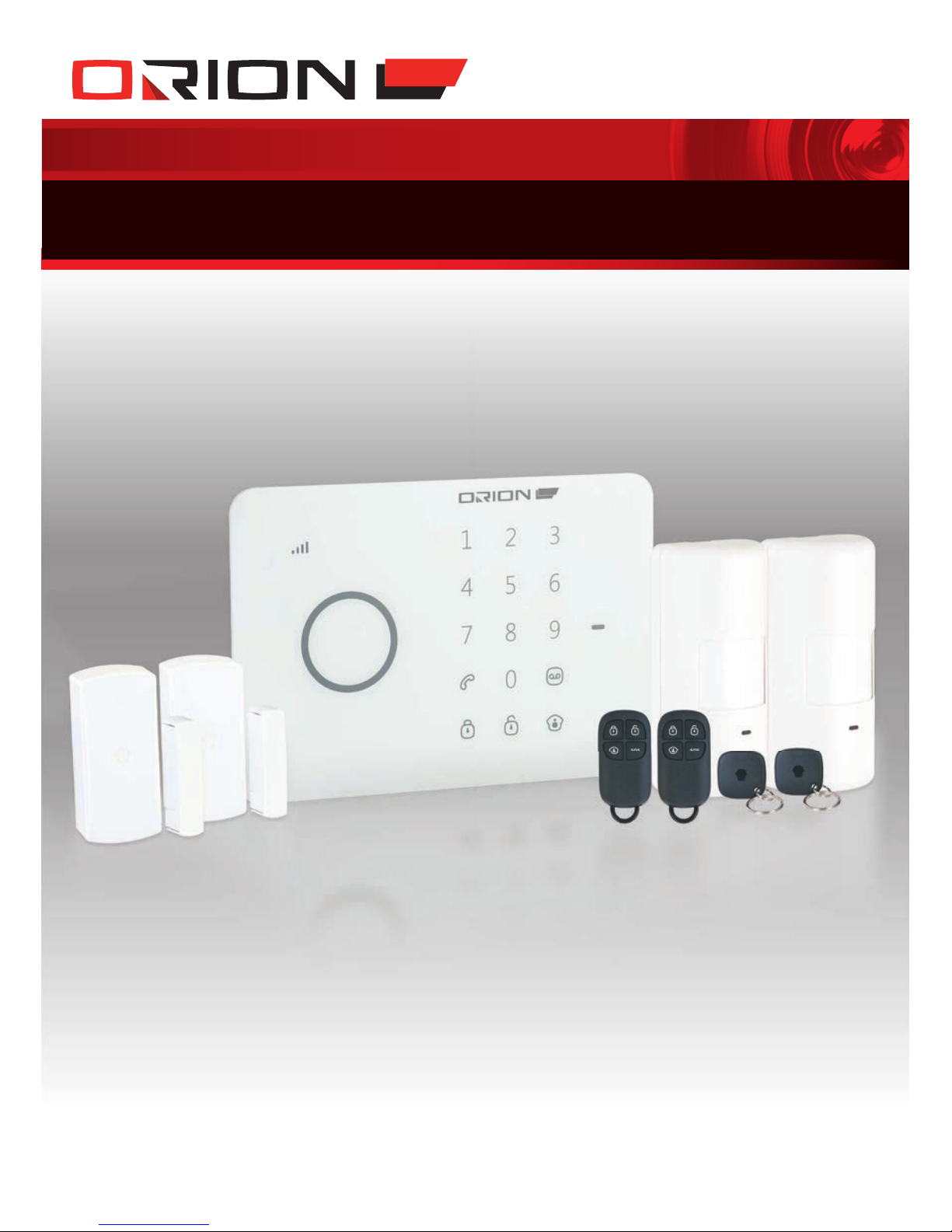
AM2000
WIRELESS AUTODIAL
HOME ALARM SYSTEM
Page 2
2
WIRELESS AUTODIAL HOME ALARM SYSTEM AM2000
PROFESSIONAL
SECURITY SYSTEM
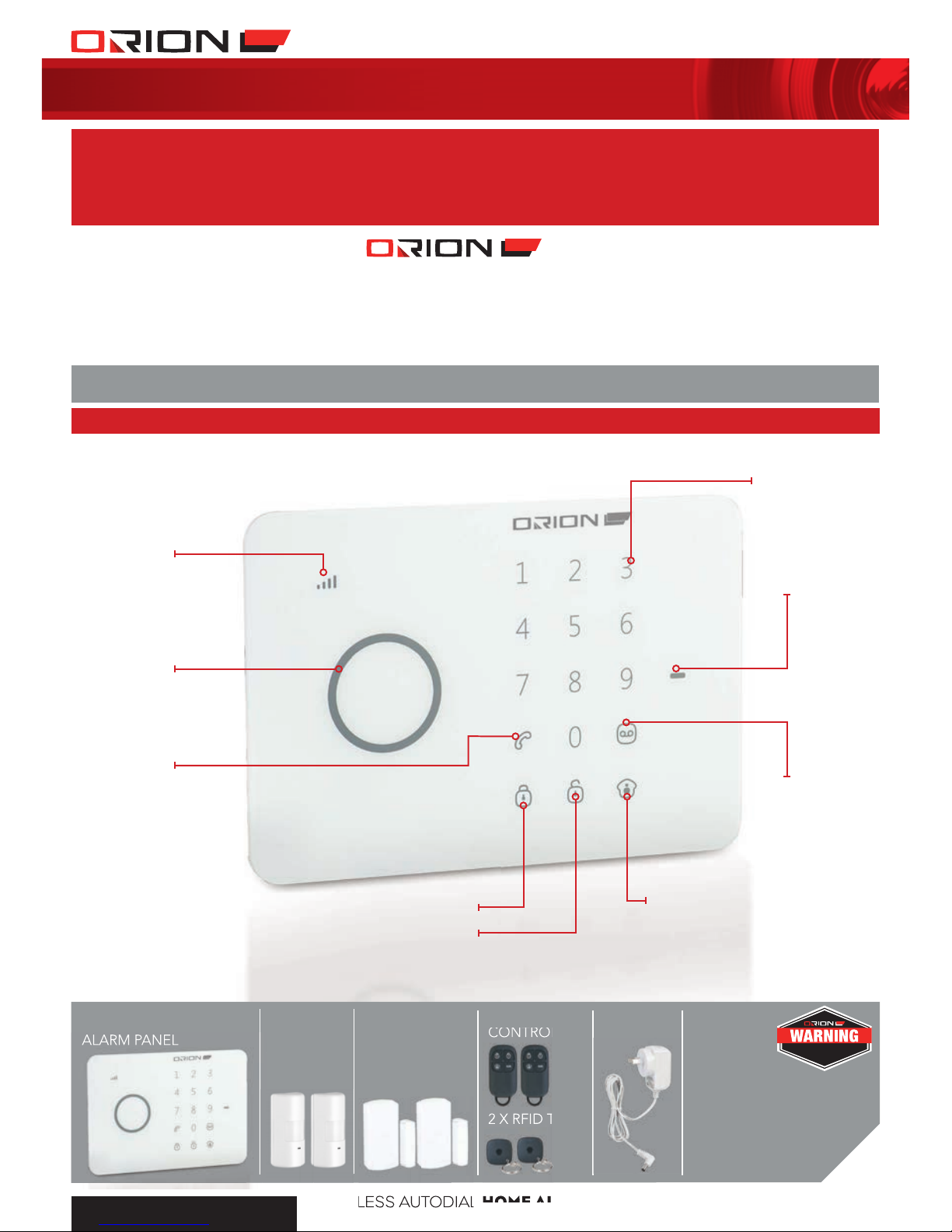
RECORD VOICE
MEMO/ CONNECT
BUTTON
STAY ARM
(HOME MODE)
DISARM
ARM
RFID READER
/ PLAY BACK
VOICE MEMO
CALL
STAT U S
INDICATOR
GSM SIGNAL
INDICATOR
ILLUMINATED
TOUCH KEYPAD
1 IDENTIFICATION
Customer Service Phone: (03) 9982 5111 (Monday to Friday 8.30am – 5.30pm EST)
Email: customerservice@orionlive.com.au
For further information visit www.orionlive.com.au
PLEASE CONTACT IF YOU HAVE ANY
CONCERNS OR PROBLEMS WITH THIS PRODUCT
IMPORTANT
BEFORE RETURNING THIS
PRODUCT TO THE RETAILER
CONTENTS:
ALARM PANEL
2 X DOOR/
WINDOW
CONTACT
SENSORS
POWER
SUPPLY
DETERRENT
STICKERS
MOUNTING SCREWS,
PLUGS AND BRACKETS
USER MANUAL
2 X PIR
MOTION
SENSORS
2 X REMOTE
CONTROLS
2 X RFID TAGS
THESE PREMISES ARE PROTECTED BY A
MULTI-DETECTION POINT
SECURITY SYSTEM
Page 3
3
WIRELESS AUTODIAL HOME ALARM SYSTEM AM2000
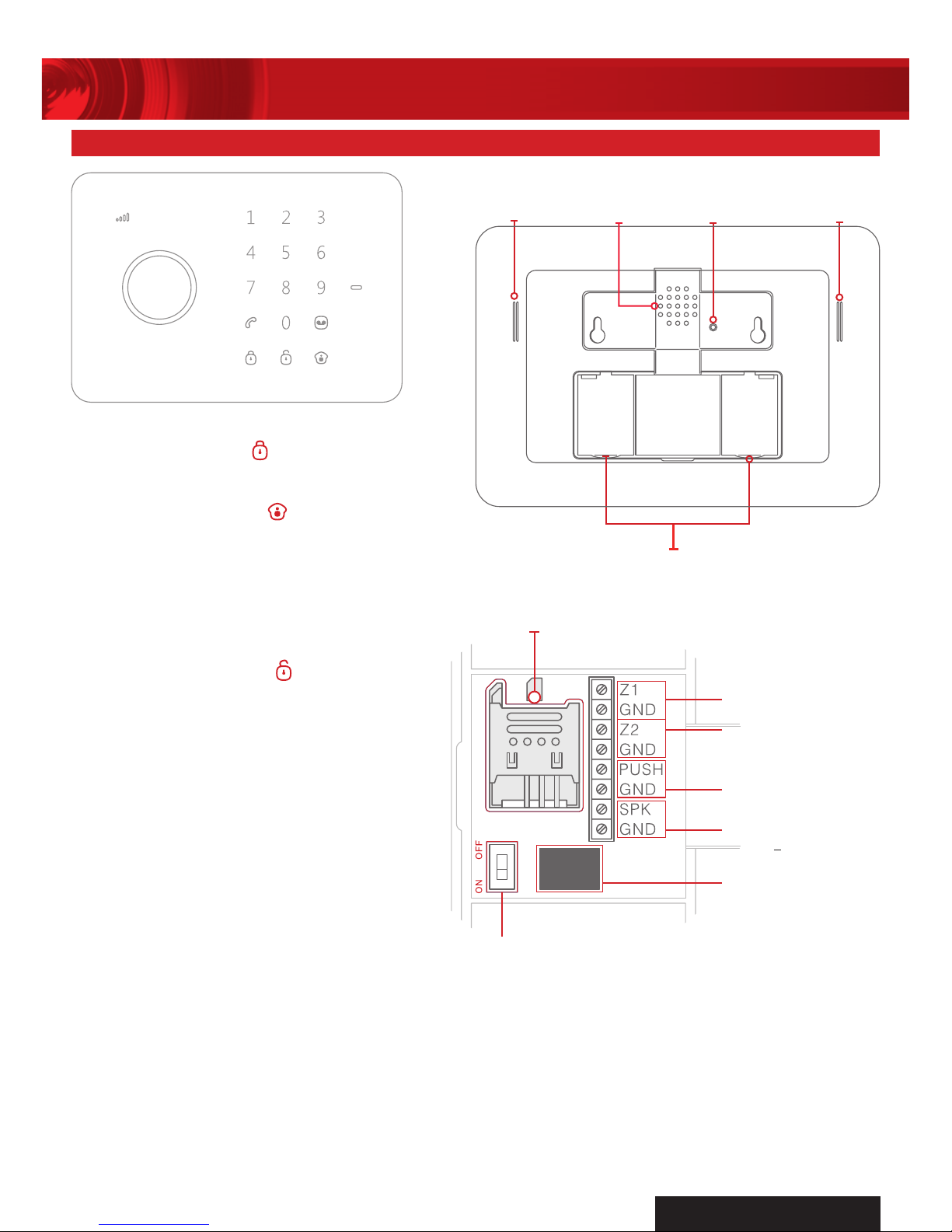
BACK-UP
BATTERIES
MICROPHONE BUZZER
TAMPER
SWITCH
LOUD
SPEAKER
2 ALARM PANEL
ARM
Press the Arm Button
to arm the system.
HOME MODE
Press the Home Button
to arm the system
in home mode. All the sensors in Normal Zone
are armed except those in Home Mode Zone
which are disarmed so that user can move
freely at home.
DISARM ON KEYPAD
Input 4 digits password (Default:1234), and
press the Disarm Button
to disarm the
system after one beep. If three beeps are
heard, password is wrong and please
input again.
DISARM BY RFID TAG
Wave the RFID tag near the RFID Reader area
to disarm the system.
GSM SIGNAL INDICATOR
GSM Networking searching:
- Flashes once every second.
GSM signal normal:
- Flashes once every 2 seconds.
IMPORTANT
A SIM card is required to access most functions of AM2000 Home Alarm System.
1. Restart the alarm panel after inserting a new SIM card.
2. SIM card not included. Please use a valid SIM card that is compatible to the GSM network with
sufficient credit to enable the GSM SMS function of AM2000 Home Alarm System.
3. Please store the AM2000 SIM card number in a safe place and keep as a secret because
AM2000 Home Alarm System can be controlled via SMS operation.
INPUT FOR POWER
SUPPLY
OUTPUT FOR WIRED
SIREN
<
500MA
OUTPUT FOR
ELECTRONIC LOCK
INPUT FOR
WIRED SENSORS
(NORMAL ZONE)
INPUT FOR
WIRED SENSORS
(24-HOUR ZONE)
POWER ON/OFF
SIM CARD SLOT
Page 4
4
WIRELESS AUTODIAL HOME ALARM SYSTEM AM2000
PROFESSIONAL
SECURITY SYSTEM
Press and hold Record Button
for 3 seconds
to record 10 seconds voice message. Or send
SMS to system for calling back to record the
voice messages (Refer to section 2.13). The
Play Voice Memo Button will be flashing in
blue to remind you. Users can touch the center
of circle to listen to the voice memo. The LED
indicator blacks out when the voice is played.
Replay by
touching
it again.
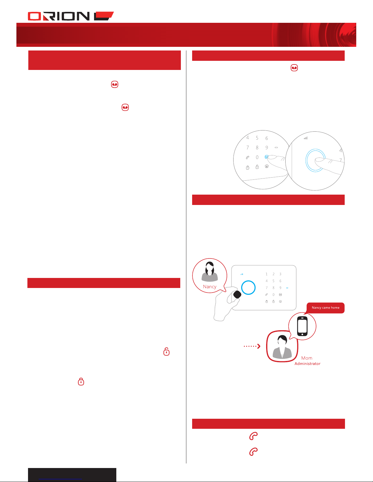
The RFID tag is for disarming the system and
unlocking the electronic door lock (if connected).
You can rename the RFID tags and store a
mobile phone number to send SMS notice
when family members come home and disarm
the system (Refer to section 2.19 and 2.24).
NOTE:
1. Only after SMS No. is stored and the RFID tags SMS
notice is changed (4 RFID tags can be renamed), users
can receive notice SMS once someone disarms the
system by RFID tag.
2. RFID tags only operate when AM2000 alarm panel is
powered by power supply.
2.3 RECORD/PLAY VOICE MEMO
2.4 RFID TAG
2.5 SPEED DIAL
1. Enter alarm panel password (Default:1234).
2. Press Connect Button
and button
illuminates.
3. Trigger signal within 15 seconds after
pressing Connect Button
.
a. AM2010 PIR Motion Sensor: Press test
button twice.
b. AM2020 Door/Window Contact Sensor:
Break contact by moving magnet away
from sensor.
c. Remote Control: Press any button on the
remote control.
d. RFID Tag: Wave RFID tag near alarm
panel RFID reader.
4. Connection successful when alarm panel
beeps once.
NOTE:
• Ifalarmpanelbeepstwice,accessoryhas
been added before.
• Alarmpanelassignszonessequentially.
The first connected accessory is assigned in
Zone 1, the second one in Zone 2 and
so on.
• Alarmpanelsupportsupto10remote
controls, 50 wireless sensors or sirens and
50 RFID tags.
2.2 CONNECT WIRELESS STROBE SIREN
2.1 CONNECT WIRELESS SENSORS,
REMOTE CONTROLS & RFID TAGS
AM2030 Strobe Siren can be added to
increase alarm visibility and audibility.
1. Open AM2030 siren front cover.
2. Press and hold tamper switch for the entire
pairing setup to avoid false tamper alarm.
3. Connect power supply to AM2030 siren.
4. Disarm AM2000 control panel by keying in
password and pressing Disarm Button
.
5. Press and hold AM2030 siren Pairing
Button for 0.5 second.
6. Arm AM2000 control panel by pressing
Arm Button
to pair with AM2030 siren.
7. When AM2030 siren beeps once, they are
paired successfully.
8. After pairing, disconnect power supply and
reassemble front cover.
9. AM2030 siren is ready for use and fixed
mounting installation.
When intruder is detected, both AM2000
control panel and AM2030 strobe light siren
will hoot to deter the intruder. The siren will
turn off in 1 minute on factory default setting.
Press Call Button
, the panel auto dials
to pre-stored phone number of the host.
Press Call Button
again to end phone call
(Refer to section 2.20).
Page 5

5
WIRELESS AUTODIAL HOME ALARM SYSTEM AM2000
Dial phone number and then press Call Button
to make phone call. Press Call Button
again to end phone call.
When system is disarmed, the output signal
opens electronic lock automatically.
Open back cover, insert SIM card and turn on
alarm panel. Wait until alarm panel acquires
GSM signal. When the GSM signal indicator
flashes every two seconds, network connection
is established.
NOTE: Please check credit on the SIM card
account periodically to ensure the GSM SMS
functionality operates correctly.
Send a text of “?” to the SIM card number,
the operation guide message will be replied.
You can control the alarm system by following
the guide message:
Send:
System replies first grade guide menu:
Send:
System replies second grade guide menu:
Send:
System replies third grade guide menu:
Send:
Send:
0
1
2.6 PHONE CALL
2.9 DISARM
2.10 ARM
2.7 ELECTRONIC LOCK OUTPUT
2.8 SMS OPERATION
Page 6
6
WIRELESS AUTODIAL HOME ALARM SYSTEM AM2000
PROFESSIONAL
SECURITY SYSTEM
Send:
NOTE:
Value of default setting will be changed once users
finish programming.
Alarm panel makes phone calls to stored
phone numbers when alarm is triggered.
Send:
Forward > Edit
00
5
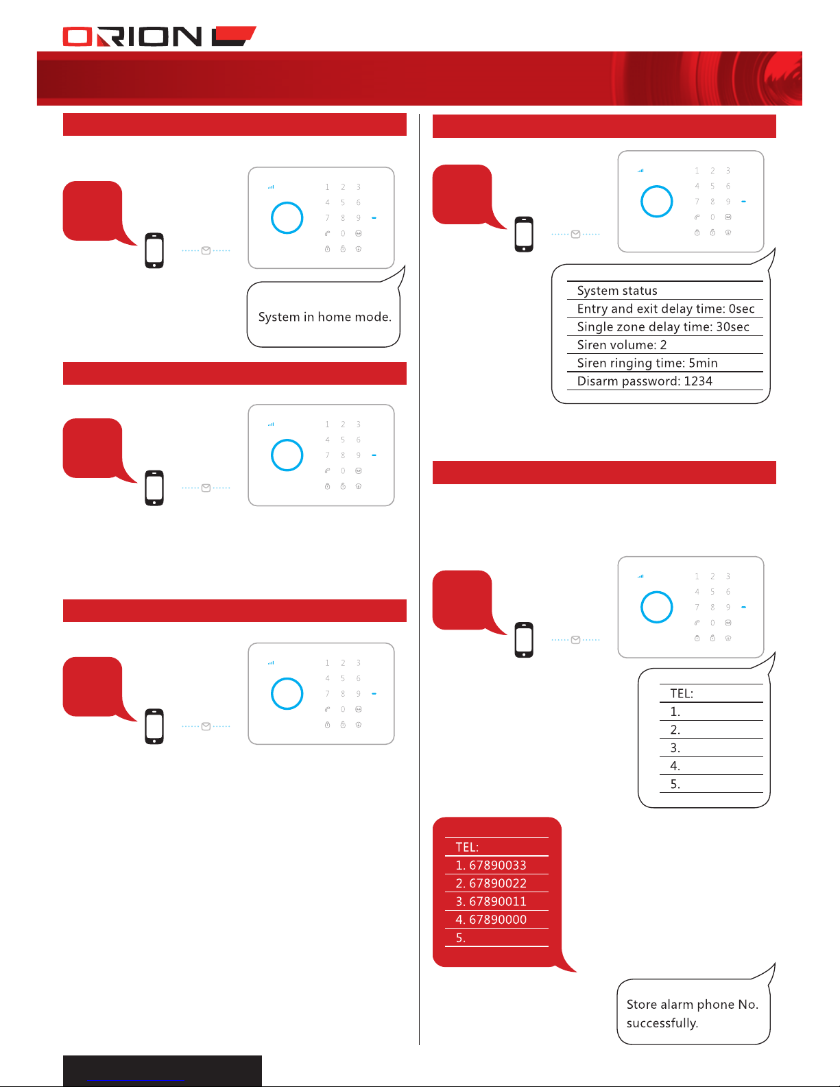
2.14 SETTINGS INQUIRY
2.15 STORE ALARM PHONE NO.
2
3
4
Send:
Send:
Send ‘3’ to the SIM card number, the alarm
will call back. Pick up the phone and start
two-way talk.
Send:
Send ‘4’ to the SIM card number, the alarm
will call back. Pick up the phone, and leave
10 seconds message. The panel will hang up
after 10 seconds.
2.11 STAY ARM (HOME MODE)
2.12 TWO-WAY TALK
2.13 CALL-BACK TO RECORD VOICE MEMO
Page 7
7
WIRELESS AUTODIAL HOME ALARM SYSTEM AM2000
6
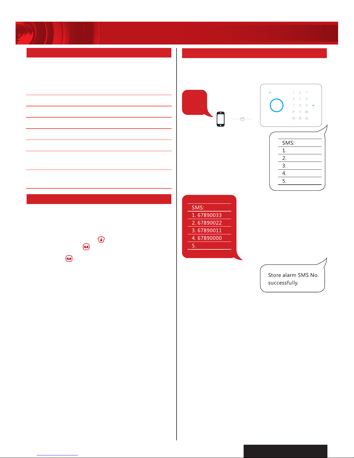
Alarm panel sends SMS notifications to stored
phone numbers when alarm is triggered.
Send:
Forward > Edit
2.16 PHONE REMOTE OPERATION
2.17 RECORD ALARM VOICE MESSAGE
2.18 STORE ALARM SMS NO.
When receiving an alarm call from alarm
panel for an emergency, the alarm system
can be controlled to perform the appropriate
operation.
ACTION OPERATION
Press 1
Arm alarm system
Press 0
Disarm alarm system
Press 9
Turn on siren to deter intruder
Press 6
Turn off siren
Press *
Two-way talk between phone
and alarm panel
Press #
Replay recorded alarm
voice message
This alarm voice message will be played when
user picks up alarm phone call.
1. Enter alarm panel password (Default:1234).
2. Press Home button
, then press
Record button
.
3. After the
button illuminates, the alarm
panel starts recording for 10 seconds.
4. Communicate an alarm message clearly to
the alarm panel microphone.
5. If the recording is successful, this voice
message will be played upon picking up
an alarm call.
Page 8

8
WIRELESS AUTODIAL HOME ALARM SYSTEM AM2000
PROFESSIONAL
SECURITY SYSTEM
2.23 SMS ALERT FOR TAMPER
ALARM OF ACCESSORIES
2.20
STORE SPEED DIAL PHONE NUMBER
Userscanchangethe1st~9thzonenames.
Thezonenameshouldbe30charactersat
most for each line due to SMS character limit.
OtheralarmzonesarexedasZone10alarm,
Zone 11 alarm and so on.
Send: Code 91 ~ 99
Forward > Edit
(Available for AM2010 only)
SMS will be sent for
1-9zoneswithits
zonenameas“Zone
name + low battery”
SMS alert for 10~50
zoneswillbe“Zone
number + low battery”
(Available for AM2010, AM2020 and AM2030)
SMS will be sent
for1-9zoneswith
itszonenameas
“Zone name +
tamper alarm”
SMS alert for
10~50zoneswill
be “Zone number
+ tamper alarm”
2.21 CHANGE ZONE NAME
2.22 SMS ALERT FOR LOW BATTERY
OF ACCESSORIES
7
8
2.19 STORE SMS NO. FOR RFID TAGS
Alarm panel sends SMS notification to stored
phone number when system is disarmed using
RFID tag.
Send:
Forward > Edit
Alarm panel speed dials stored phone number
when Call Button
is pressed.
Send:
Forward > Edit
NOTE:
1 Only after SMS No. is
stored and the RFID
tags SMS notice is changed, users can receive notice SMS once
someone disarms the system by RFID tag.
2. RFID tags only operate when AM2000 alarm panel
is powered by power supply.
91
Page 9
9
WIRELESS AUTODIAL HOME ALARM SYSTEM AM2000
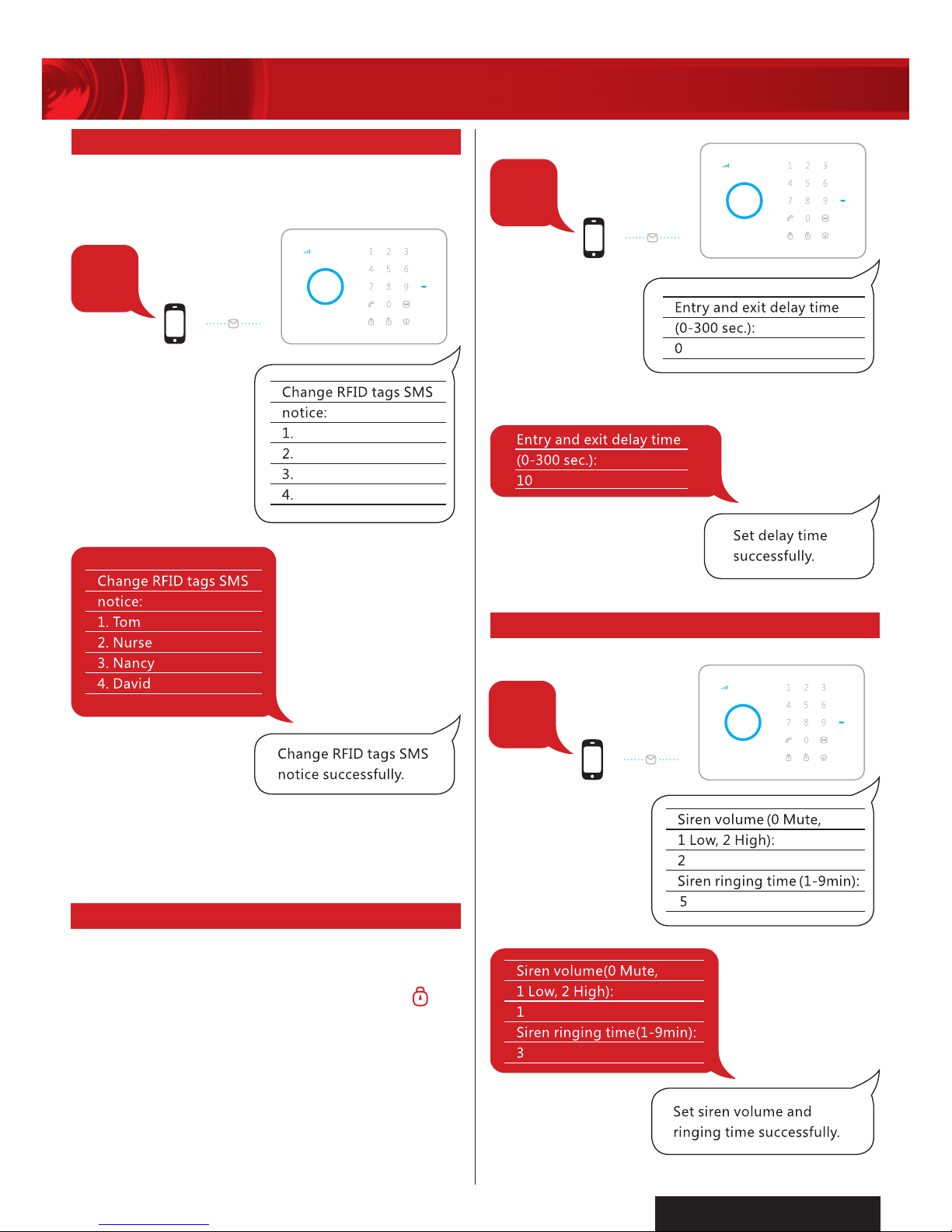
RFID tags can be associated with users by
assigning names to the tags.
Send
Forward > Edit
NOTE:
Only after SMS No. is stored and the RFID tags SMS notice
is changed, users can receive notice SMS once someone disarms the
system by RFID tag.
Delay time is required when arming or
disarming without the use of remote control
and RFID tag. After pressing Arm Button
,
the alarm panel will change to Armed state
after this delay time. This allows the user to
exit the premises without triggering the alarm.
Alarm will beep every second to remind
user to exit premises. The reminder beep
speeds up in the last 15 seconds. If intruder is
detected, the alarm is delayed based on this
delay time.
10
11
Send:
Forward > Edit
2.24 CHANGE RFID TAGS SMS NOTICE
2.25 ENTRY AND EXIT DELAY TIME
12
Send:
Forward > Edit
2.26 SIREN VOLUME AND RINGING TIME
Page 10

10
WIRELESS AUTODIAL HOME ALARM SYSTEM AM2000
PROFESSIONAL
SECURITY SYSTEM
Send:
22
2.31 DELETE RFID TAGS BY SMS
Send:
Or press Tamper Switch 3 times within 3 sec.,
accessories will be cleared after two beeps.
21
2.30 DELETE WIRELESS
ACCESSORIES BY SMS
14
0086
0001
When a sensor which is set to Single Zone
Delay mode detects intruder, alarm panel will
only trigger alarm after this delay time.
Send:
Forward > Edit
Send: 0086 to change language to Chinese
Send: 0001 to change language to English
13
Send:
Forward > Edit
2.27 CHANGE DISARM PASSWORD
2.28 SINGLE ZONE DELAY TIME
2.29 CHANGE SYSTEM LANGUAGE
NOTE:
It is recommended to change alarm panel password
immediately after installation.
Page 11
11
WIRELESS AUTODIAL HOME ALARM SYSTEM AM2000
› Arm
1. Call alarm panel by dialling SIM card number.
2. Hang up after hearing ring tone.
3. Alarm panel will call back.
4. Reject the call back.
5. Alarm panel is armed.
› Disarm
1. Call alarm panel by dialling SIM card number.
2. Hold on until alarm panel hangs up the call.
3. Alarm panel will not call back.
4. Alarm panel is disarmed.
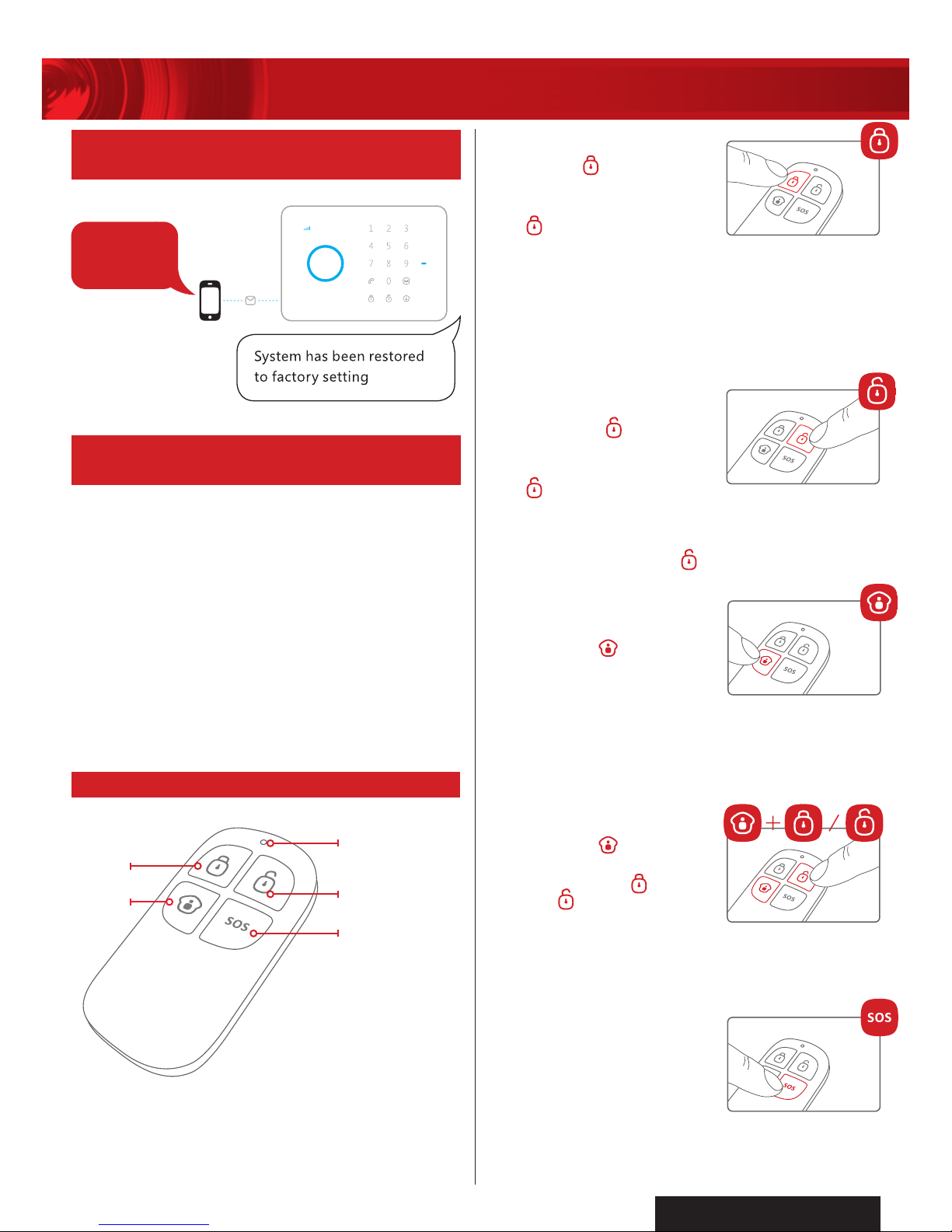
› Arm
Press (Arm
) to arm the
alarm panel.When the
alarm panel beeps once
and
button illuminates,
the system is armed.
When intruders are detected, the siren will
hoot to deter the intruder. (The siren turns off
after ringing for 1 minute in default setting.)
At the same time, the alarm panel dials the
pre-stored phone numbers automatically.
› Disarm
Press (Disarm
) to disarm
the alarm panel. When the
alarm panel beeps twice
and
button illuminates,
the system is disarmed.
When intruders are detected, siren will keep
hooting. Press (Disarm
) to stop
siren hooting.
› Home Mode
Press (Home
) to arm the
home mode.
All the sensors in Normal Zone are armed
except those in Home Mode Zone which
are disarmed so that user can move freely at
home.
› Mute Mode
Press (Home
) button
on the remote control,
then press (Arm
) or
(Disarm
) button, the
siren keeps silent to
finish the operation. The system is armed or
disarmed in mute without hooting to avoid
disturbing other people.
› Emergency Call
No matter what state the
control panel is in, once
SOS Button on the remote
is pressed, the system
immediately goes into
emergency alarm state.
0000
3 WIRELESS REMOTE CONTROL
LED INDICATOR
DISARM
ARM
HOME
PANIC
2.33 ARM & DISARM BY FREE
PHONE CALL
2.32 RESTORE SYSTEM TO DEFAULT
SETTING BY SMS
Send:
NOTE:
Do not press and hold more than one button at the time.
After a button is pressed, please wait for 5 seconds for the
command to be completed.
Page 12

12
WIRELESS AUTODIAL HOME ALARM SYSTEM AM2000
PROFESSIONAL
SECURITY SYSTEM
4 WIRELESS MOTION SENSOR
110˚/8m
GROUND
TOP VIEW SIDE VIEW
DETECTION
WINDOW
LED INDICATOR
OUTER
ENCLOSURE
REAR VIEW
FRONT VIEW
BRACKET
TEST
BUTTON
1. Fix the mounting bracket on the wall
with screws and attach the sensor
to the bracket.
2. Adjust installation height or bracket to
change the detection distance and angle.
It is recommended to mount the sensor at
the height of 2m from the ground.
NOTE – the sensor is more sensitive
to movement across the sensor rather than
towards it, so the sensor functions best when it
is positioned to one side of a walkway.
SENSOR – detects the motion of infra-red rays
released by human body and animals, or heat
sources. Do not touch the sensor and always
keep the detection window clean.
TAMPER SWITCH – when the case is opened
during armed state, the tamper switch will be
triggered and generate a signal to alarm the
AM2000 control panel.
LED ON/OFF – set the jumper to ON or OFF
position to activate or deactivate LED indication.
ZONE SETTING – set the jumpers to different
zonemodefordifferentalarmactivation
method.
4.1 INSTALLATION AND NOTICES
4.3 INTERNAL AND FUNCTIONS
NOTE – if two sensors are installed in the
same detection range, please adjust the
location and height of each unit to avoid
interference and false triggering.
4.2 DETECTION RANGE
TOP VIEW SIDE VIEW
Page 13

13
WIRELESS AUTODIAL HOME ALARM SYSTEM AM2000
IMPORTANT – WHEN THE ZONE SETTING
IS CHANGED, THE SENSOR MUST RE-PAIR
WITH AM2000 CONTROL PANEL.
HOME MODE
ZONE
NORMAL
ZONE
SINGLE DELAY
ZONE
TAMPER
SWITCH
ZONE SETUP
LED ON/OFF
SENSOR
HOME MODE ZONE – when home mode
button is pressed on AM2000 control panel
or the remote control, it will not trigger the
alarm, and therefore occupants can move
freelyinsidetheroom.Meanwhileotherzone
setting will remain armed.
NORMAL ZONE – when AM2000 is armed,
if intruder detected, it will trigger alarm
immediately.
SINGLE DELAY ZONE – when AM2000 is
armed, if intruder detected, it will trigger alarm
after 30 seconds time delay in default settings.
NOTE: AM2010 PIR motion sensor is set to
“HOME MODE ZONE” by default.
Open the case with a screw driver and remove
the battery insulation strip to power on the sensor.
Once the sensor is powered on, it will start
self testing for one minute.
TESTING MODE: After self testing, press
the test button on the rear of the sensor, the
sensor enters into testing mode, and detects
once every 10 seconds, walk within the
detection range, from left to right or right to
left and monitor the LED indicator to ensure
the detector is working.
Adjust the sensor angle accordingly to achieve
best detection effect. After 3 minutes, the LED
flashes twice, and the sensor enters working
mode.
WORKING MODE: in working mode, if the
sensor is triggered more than twice within
3 minutes, it will enter standby mode to save
power. After no movement within next 3 minutes,
the sensor goes back to the working mode.
› Pairing with AM2000 control panel
Key in the password and press the connect
key on AM2000 control panel, and then press
the test button twice on the back of the sensor
unit. When one beep sound from the AM2000
control panel is heard, they are paired.
To check if they are connected successfully,
arm the AM2000 control panel, trigger the
sensor by walking within the detection range
after exit delay time; if there is an alarm, the
connection is successful.
› LED indication
FLASH CONTINUOUSLY –
under self testing mode.
FLASH ONCE – intruder detected.
FLASH TWICE – self testing mode completed,
enter to working mode.
FLASH ONCE PER 3 SECONDS – low battery
indication, please change batteries immediately,
user will get alert SMS for low battery if the PIR
motion sensor is connected to AM2000 control
panel with GSM enabled.
4.4 OPERATION
Page 14

14
WIRELESS AUTODIAL HOME ALARM SYSTEM AM2000
PROFESSIONAL
SECURITY SYSTEM
LED INDICATOR
MAGNETSENSOR
5 WIRELESS MOTION SENSOR
TAMPER SWITCH – when the case
is opened during armed state, the
tamper switch will be triggered
and generate a signal to alarm the
AM2000 control panel.
TAMPER SWITCH
ZONE SETUP
1. Slide open the rear case and remove
battery insulation strip.
2. Mount the sensor on the door frame
and the magnet on the door.
3. Ensure the magnet is on the right side of
the sensor where the arrow is located.
4. Place the sensor in the desired location;
mount the magnet no more than 10mm
away from the sensor and secure the
sensor and magnet with double sided
tapes (supplied) or screws (not supplied).
5. Avoid mounting sensors in areas with large
quantity of metal or electrical wiring, such
as full metal frame and door, furnace or
utility room.
Pairing with AM2000 control panel
Key in the password and press the connect
key on AM2000 control panel, then trigger
the sensor by opening the door it is mounted
on. When one beep sound from the AM2000
control panel is heard, they are paired.
To check if they are connected successfully, arm
the AM2000 control panel, trigger the sensor
unit by opening the door it is mounted on; if
there is an alarm, the connection is successful.
5.1 INSTALLATION AND NOTICES
5.2 INTERNAL AND FUNCTIONS
5.3 OPERATION
IMPORTANT – Whenthezonesettingischanged,the
sensor must re-pair with am2000 control panel.
HOME MODE
ZONE
NORMAL
ZONE
SINGLE DELAY
ZONE
ZONE SETTING – set the jumpers to
differentzonemodefordifferentalarm
activation method.
HOME MODE ZONE – when home mode
button is pressed on AM2000 control panel
or the remote control, it will not trigger the
alarm, and therefore occupants can move
freelyinsidetheroom.Meanwhileotherzone
setting will remain armed.
NORMAL ZONE – when AM2000 is armed,
if intruder detected, it will trigger alarm
immediately.
SINGLE DELAY ZONE – when AM2000 is
armed, if intruder detected, it will trigger alarm
after 30 seconds time delay in default settings.
NOTE: AM2020 wireless door/window contact
sensor is set to “SINGLE DELAY ZONE”
by default.
Page 15

15
WIRELESS AUTODIAL HOME ALARM SYSTEM AM2000
6 SPECIFICATIONS
* Range depends on location, temperature and battery conditions.
›ALARM PANEL
Power Supply DC 12V 500mA
Power Consumption 5W Max
GSM Frequency 850/900/1800/1900MHz
Radio Frequency 433MHz
Backup Battery 2 x Lithium-ion
3.7V/800mAh (Included)
Inbuilt Siren 110dB
Operating Temperature 10°C~55°C
Operating Humidity < 80% (non-condensing)
Dimensions 188(L) x 132(W) x 26(H)mm
›PIR MOTION SENSOR
Power Supply DC 3V (2 x AA Alkaline
Battery Included)
Power Consumption 0.03W Max
Detection Scope 8m/110°
Wireless Range Up to 50m*
Radio Frequency 433MHz
Operating Temperature -10°C~55°C
Operating Humidity < 80%
Dimensions Sensor: 108(L) x
52(W) x 36.8(H)mm
Bracket: 52(L) x
30(W) x 26.5(H)mm
›DOOR/WINDOW CONTACT SENSOR
Power Supply DC 1.5V (AA Alkaline
Battery Included)
Power Consumption 0.06W Max
Wireless Range Up to 50m*
Radio Frequency 433MHz
Operating Temperature 10°C~55°C
Operating Humidity < 80%
Dimensions Sensor: 71(L) x
34(W) x 17.5(H)mm
Magnet: 51(L) x
12(W) x 13.5(H)mm
7 WARNING
› Do not drop, puncture, or violently
shake the unit.
› Do not mount, directly expose or put
near to the sun, water, air conditioner,
refrigerator radio transmitting devices,
metal objects, heater, oven, any heat
sources, rapid temperature changing or
high air flow locations.
› Do not cover the unit, mount the unit on
adequate locations and heights.
› Handle the unit with care, avoid
unnecessary force or impact.
› This unit is for indoor use only.
8 ALARM MONITORING SERVICE
For added security, use this alarm system in
conjunction with alarm monitoring service for
rapid response to an emergency.
Contact your local alarm monitoring service
provider to establish a response plan.
Page 16

CPIN002639/2
PROFESSIONAL
SECURITY SYSTEM
10 WARRANTY
Arlec guarantees this product in accordance with the Australian Consumer Law.
Arlec also warrants to the original first purchaser of this product (“you”)
from a retailer that this product will be free of defects in materials and
workmanship for a period of 12 months from the date of purchase;
provided the product is not used other than for the purpose, or in a
manner not within the scope of the recommendations and limitations,
specified by Arlec, is new and not damaged at the time of purchase, has
not been subjected to abuse, misuse, neglect or damage, has not been
modified or repaired without the approval of Arlec and has not been used
for commercial purposes (“Warranty”).
If you wish to claim on the Warranty, you must, at your own expense,
return the product, and provide proof of original purchase and your name,
address and telephone number, to Arlec at the address below or the
retailer from whom you originally purchased the product within 12 months
from the date of purchase.
Arlec will (or authorise the retailer to) assess any claim you may make on
the Warranty in the above manner and if, in Arlec’s reasonable opinion, the
Warranty applies, Arlec will at its own option and expense (or authorise
the retailer to) replace the product with the same or similar product or
repair the product and return it to you or refund the price you paid for the
product. Arlec will bear its own expenses of doing those things, and you
must bear any other expenses of claiming on the Warranty.
The Warranty is in addition to other rights and remedies you may have
under a law in relation to the product to which the Warranty relates.
Our goods come with guarantees that cannot be excluded under the
Australian Consumer Law. You are entitled to a replacement or refund for
a major failure and for compensation for any other reasonably foreseeable
loss or damage. You are also entitled to have the goods repaired or
replaced if the goods fail to be of acceptable quality and the failure does
not amount to a major failure.
Arlec Australia Pty. Ltd. ACN 009 322 105 (“Arlec”) gives the Warranty.
Arlec’s telephone number, address and email address are:
Customer Service: (03) 9982 5111
New Zealand Toll Free: 0800 003 329
Building 3, 31 – 41 Joseph Street, Blackburn North, Victoria, 3130
Blackburn North LPO, P.O. Box 1065, Blackburn North, 3130
Email: custservice@arlec.com.au
PROBLEM
POSSIBLE
CAUSE
SUGGESTED REMEDY
No power or
not powering up
Battery is loose/
low battery or
power supply is
unplugged.
Check battery and power supply installation.
Check power point. Ensure battery and
power supply are secured.
No LED indication
LED indication
is turned off.
Battery is loose,
unplugged or low
battery.
Replace battery, alkaline type battery
recommended. Ensure battery is secured.
Turn on AM2010 Motion Sensor LED by setting the
jumper to ON position.
Poor/No signal
on sensors
Signal interference,
out of transmission
range or low
battery.
Relocate sensors away from water, air conditioner,
refrigerator radio transmitting devices, metal objects,
heater, oven, any heat sources, rapid temperature
changing, high air flow locations or major obstacles.
Relocate sensors closer to AM2000 alarm panel.
Replace battery on all sensors and check power supply
on AM2000 alarm panel.
Poor/ No signal on
GSM network
Check the SIM card is activated and has sufficient credit.
Check the SIM card is compatible to the GSM network
850/900/1800/1900MHz.
Check the SIM card account periodically to ensure
there is sufficient credit for the GSM SMS function to
operate correctly.
No interaction
between sensor
and AM2000
control panel
The sensor and
AM2000 alarm
panel are not
paired.
Please pair the sensor and AM2000 alarm panel
following pairing instruction.
9 TROUBLESHOOTING GUIDE
 Loading...