

Page 1
Installation Guide
ALLED3 Series Area Light
SAVE THESE INSTRUCTIONS
BEFORE YOU
Read and follow
all
safety
BEGIN
instructions
WARNING
RISK OF FIRE, EXPLOSION AND ELECTRIC SHOCK
• This product should be installed, inspected, and maintained by a qualified electrician only,
in accordance with the NEC (National Electric Code) and all local codes.
• Turn off electrical power before inspection, installation or removal.
• Use only UL (or other NTRL) approved wire for input/output connections.
Minimum size 18 AWG or 14 AWG for continuous runs.
• Make sure LEDs and drivers are cool to touch when performing maintenance.
Make sure the supply voltage is the same as the rated voltage of the luminaire.
• Do not install in a hazardous atmosphere, except where the ambient temperature does
not exceed the rated operating temperature of the fixture.
•
Keep tightly closed when in operation
Prepare Electrical Wiring
Electrical Requirements
The LED driver must be supplied with 120 to 277V, 50/60 Hz
and connected to an individual, properly grounded branch circuit
protected by a 20 Ampere circuit breaker. Use min. 75°C supply.
Grounding Instructions
The grounding and bonding of the overall system shall be
done in accordance with NEC Article 600 and local codes
Page 2
LED Area Light
Tools Required:
Phillips Screw Drivers
Wire Strippers
of the pole.
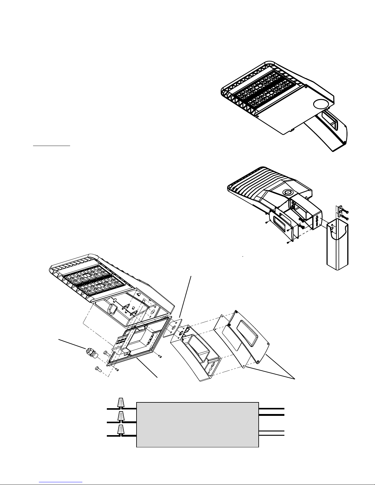
LED Driver
BLACK
WHITE
GREEN
LINE
NEUTRAL
GROUND
RED
BLACK
PURPLE
GRAY
V+
V-
DIM+
DIM-
Strain relief
Fixture mount gasket
Pole mount arm gasket and cover
LED driver door
Wiring Diagram
ALLED3 Series
Wire Cutters
Hex Bit Socket or Combo Wrench (1/
• Before starting ensure that the power is disconnected.
• Unpack fixture and ensure that there are no damaged part
• Pole Mounting:
• Remove the pole mounting arm cover and gasket.
• Feed the included bolts, lock and flat washers through the mounting arm holes.
• Align with the holes in the pole and thread through the plate on the inside
• Hand tighten the bolts to 20 lbf-in.
• Open the LED driver compartment from the underside of the fixture.
• Feed the included bolts, lock and flat washers through the inside of the driver
compartment, fixture mount gasket, and attach the fixture to the pole mount.
• Feed the power cable through the strain relief and pole mount arm and
connect the power leads with the included wire nuts according to the wiring
diagram below.
• Close the LED driver compartment door and secure with the supplied screws.
• Replace the pole mount arm gasket and attach the cover with the supplied screws.
Make sure the strain relief is installed correctly.
2")
s.
Installation
Guide
IS-6090-180827
 Loading...