

Page 1
AGB-21G
SERVICE MANUAL
Page 2
Page 3
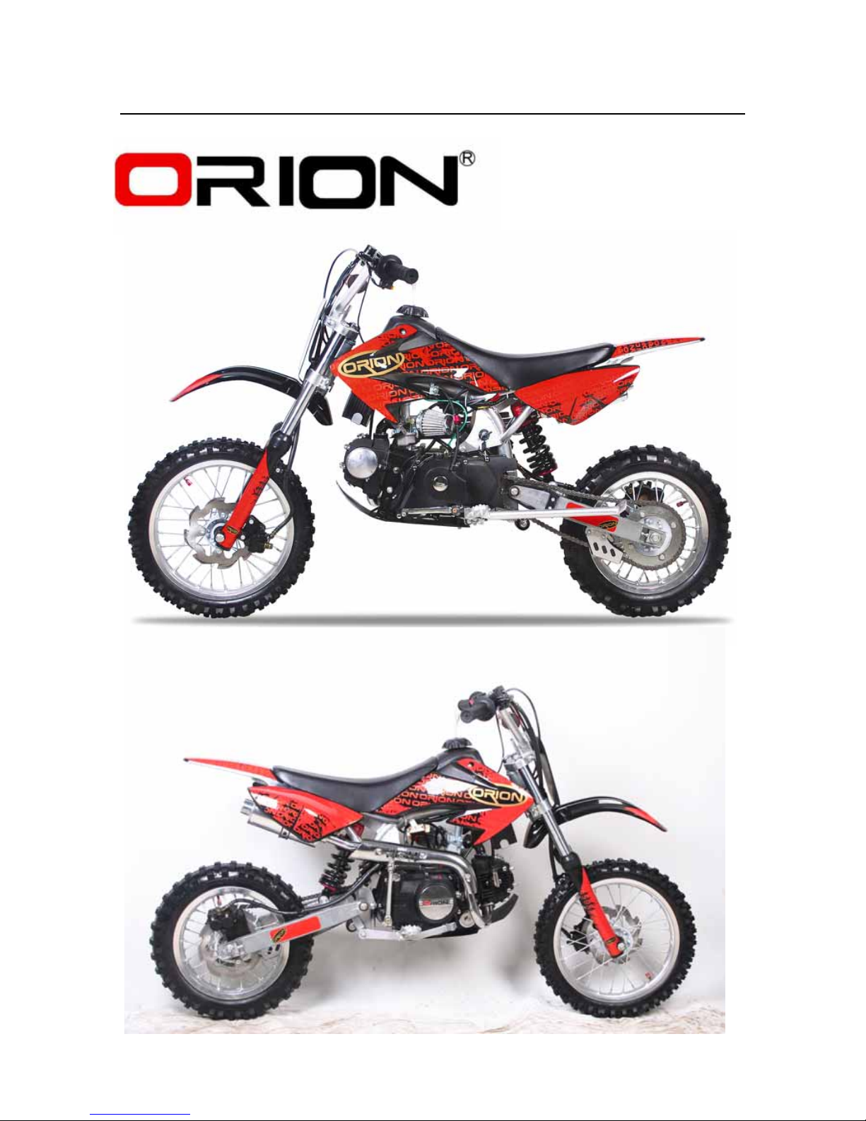
Congratulations on your purchase of an
Apollo AGB-21G.
127(
As improvements are made on this model,
some data in this manual may become out-
dated. If you have any questions, please con-
sult your dealer.
WARNING
PLEASE READ THIS MANUAL CAREFULLY
AND COMPLETELY BEFORE OPERATING
THIS MACHINE. DO NOT ATTEMPT TO
OPERATE THIS MACHINE UNTIL YOU
HAVE ATTAINED A SATISFACTORY
KNOWLEDGE OF ITS CONTROLS AND
OPERATING FEATURES AND UNTIL YOU
HAVE BEEN TRAINED IN SAFE AND
PROPER RIDING TECHNIQUES. REGULAR
INSPECTIONS AND CAREFUL MAINTENANCE, ALONG WITH GOOD RIDING
SKILLS, WILL ENSURE THAT YOU SAFETY
ENJOY THE CAPABILITIES AND THE RELIABILITY OF THIS MACHINE.
IMPORTANT NOTICE
THIS MACHINE IS DESIGNED STRICTLY
FOR COMPETITION USE, ONLY ON A
CLOSED COURSE. It is illegal for this
machine to be operated on any public street,
road, or highway. Off-road use on public lands
may also be illegal. Please check local regulations before riding.
1. THIS MACHINE IS TO BE OPERATED
BY AN EXPERIENCED RIDER ONLY.
Do not attempt to operate this
machine at maximum power until you
are totally familiar with its characteristics.
2. THIS MACHINE IS DESIGNED TO BE
RIDDEN BY THE OPERATOR ONLY.
Do not carry passengers on this
machine.
3. ALWAYS WEAR PROTECTIVE
APPAREL.
When operating this machine, always
wear an approved helmet with goggles or a face shield. Also wear heavy
boots, gloves, and protective clothing. Always wear proper fitting clothing that will not be caught in any of
the moving parts or controls of the
machine.
4. ALWAYS MAINTAIN YOUR MACHINE
IN PROPER WORKING ORDER.
For safety and reliability, the machine
must be properly maintained. Always
perform the pre-operation checks
indicated in this manual. Correcting a
mechanical problem before you ride
may prevent an accident.
5. GASOLINE IS HIGHLY FLAMMABLE.
Always turn off the engine while refueling. Take care to not spill any gasoline on the engine or exhaust system.
Never refuel in the vicinity of an open
flame, or while smoking.
SAFETY INFORMATION
II
INTRODUCTION
Page 4

6. GASOLINE CAN CAUSE INJURY.
If you should swallow some gasoline,
inhale excess gasoline vapors, or
allow any gasoline to get into your
eyes, contact a doctor immediately. If
any gasoline spills onto your skin or
clothing, immediately wash skin areas
with soap and water, and change your
clothes.
7. ONLY OPERATE THE MACHINE IN AN
AREA WITH ADEQUATE VENTILATION.
Never start the engine or let it run for
any length of time in an enclosed area.
Exhaust fumes are poisonous. These
fumes contain carbon monoxide,
which by itself is odorless and colorless. Carbon monoxide is a dangerous
gas which can cause unconsciousness or can be lethal.
8. PARK THE MACHINE CAREFULLY;
TURN OFF THE ENGINE.
Always turn off the engine if you are
going to leave the machine. Do not
park the machine on a slope or soft
ground as it may fall over.
9. THE ENGINE, EXHAUST PIPE, MUFFLER, AND OIL TANK WILL BE VERY
HOT AFTER THE ENGINE HAS BEEN
RUN.
Be careful not to touch them or to
allow any clothing item to contact
them during inspection or repair.
10. PROPERLY SECURE THE MACHINE
BEFORE TRANSPORTING IT.
When transporting the machine in
another vehicle, always be sure it is
properly secured and in an upright
position and that the fuel cock is in
the “ OFF ” position. Otherwise, fuel
may leak out of the carburetor or fuel
tank.
Page 5
TO THE NEW OWNER
This manual will provide you with a good basic
understanding of features, operation, and
basic maintenance and inspection items of this
machine. Please read this manual carefully
and completely before operating your new
machine. If you have any questions regarding
the operation or maintenance of your machine,
please consult your dealer.
NOTE:
This manual should be considered a permanent part of this machine and should remain
with it even if the machine is subsequently
sold.
NOTICE
Some data in this manual may become outdated due to improvements made to this
model in the future. If there is any question
you have regarding this manual or your
machine, please consult your dealer.
F.I.M. MACHINE WEIGHTS:
Weights of machines without fuel
The minimum weights for motocross
machines are:
for the class 125cc.......................minimum
64 kg
In modifying your machine (e.g., for weight
reduction), take note of the above limits of
weight.
HOW TO USE
THIS MANUAL
PARTICULARLY IMPORTANT
INFORMATION
The Safety Alert Symbol means ATTENTION!
BECOME ALERT! YOUR SAFETY IS
INVOLVED!
Failure to follow WARNING instructions could
result in severe injury or death to the machine
operator, a bystander, or a person inspecting
or repairing the machine.
A CAUTION indicates special precautions that
must be taken to avoid damage to the
machine.
NOTE:
A NOTE provides key information to make procedures easier or clearer.
WARNING
CAUTION:
MANUAL FORMAT
All of the procedures in this manual are organized
in a sequential, step-by-step format. The information has been complied to provide the mechanic
with an easy to read, handy reference that contains
comprehensive explanations of all disassembly,
repair, assembly, and inspection operations.
In this revised format, the condition of a faulty
component will precede an arrow symbol and the
course of action required will follow the symbol, e.g.,
Bearings
Pitting/damage → Replace.
Page 6
INDEX
GENERAL INFORMATION
1
SPECIFICATIONS
2
REGULAR INSPECTION AND ADJUSTMENTS
ENGINE
CHASSIS
ELECTRICAL
3
4
5
6
7
Page 7
1 - 1
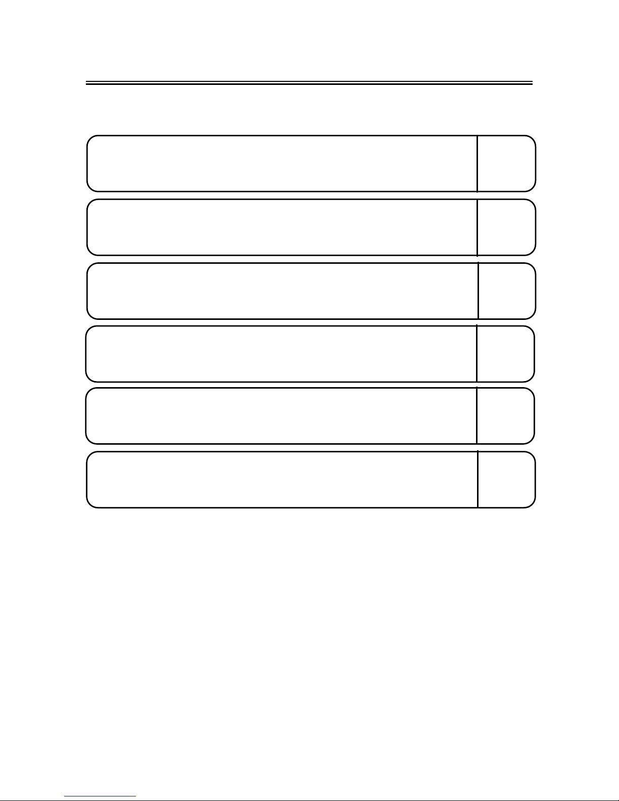
DESCRIPTION
GENERAL INFORMATION
DESCRIPTION
2 Clutch lever
3 Engine stop switch
4 Front brake lever
5 Throttle grip
6 Fuel tank cap
7 Engine start switch
8
9
:
Fuel tank
21
Air filter
22
Left side cover
23
Drive chain
24
Shift pedal
25
Side stand
26
Fuel cock
27
Spark plug
28
Right side cover
29
Kick starter cank
2:
Front fork
NOTE:
The machine you have purchased may differ
slightly from those shown in the following.
Designs and specifications are subject to
change without notice.
Rear brake pedal
Front axle
Page 8
1 - 2
MACHINE IDENTIFICATION
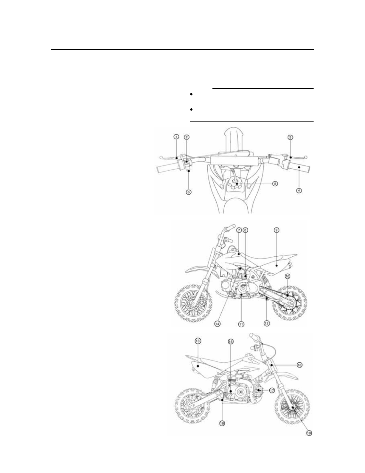
MACHINE IDENTIFICATION
There are two significant reasons for knowing
the serial number of your machine:
1. When ordering parts, you can give the
number to your dealer for positive
identification of the model you own.
2. If your machine is stolen, the authorities
will need the number to search for and
identify your machine.
VEHICLE IDENTIFICATION NUMBER
The vehicle identification number ① is
stamped on the right of the steering head pipe.
ENGINE SERIAL NUMBER
The engine serial number ② is stamped into
the elevated part of the right-side of the
engine.
ķ
Page 9

1 - 3
IMPORTANT INFORMATION
IMPORTANT INFORMATION
PREPARATION FOR REMOVAL AND
DISASSEMBLY
1. Remove all dirt, mud, dust, and foreign
material before removal and disassembly.
When washing the machine with high
pressured water, cover the parts follows.
Silencer exhaust port
Side cover air intake port
2. Use proper tools and cleaning equipment. Refer to “SPECIAL TOOLS” section.
3. When disassembling the machine, keep
mated parts together. They include
gears, cylinders, pistons, and other
mated parts that have been “mated”
through normal wear. Mated parts must
be reused as an assembly or replaced.
4. During the machine disassembly, clean
all parts and place them in trays in the
order of disassembly. This will speed up
assembly time and help assure that all
parts are correctly reinstalled.
5. Keep away from fire.
Page 10
1 - 4
IMPORTANT INFORMATION
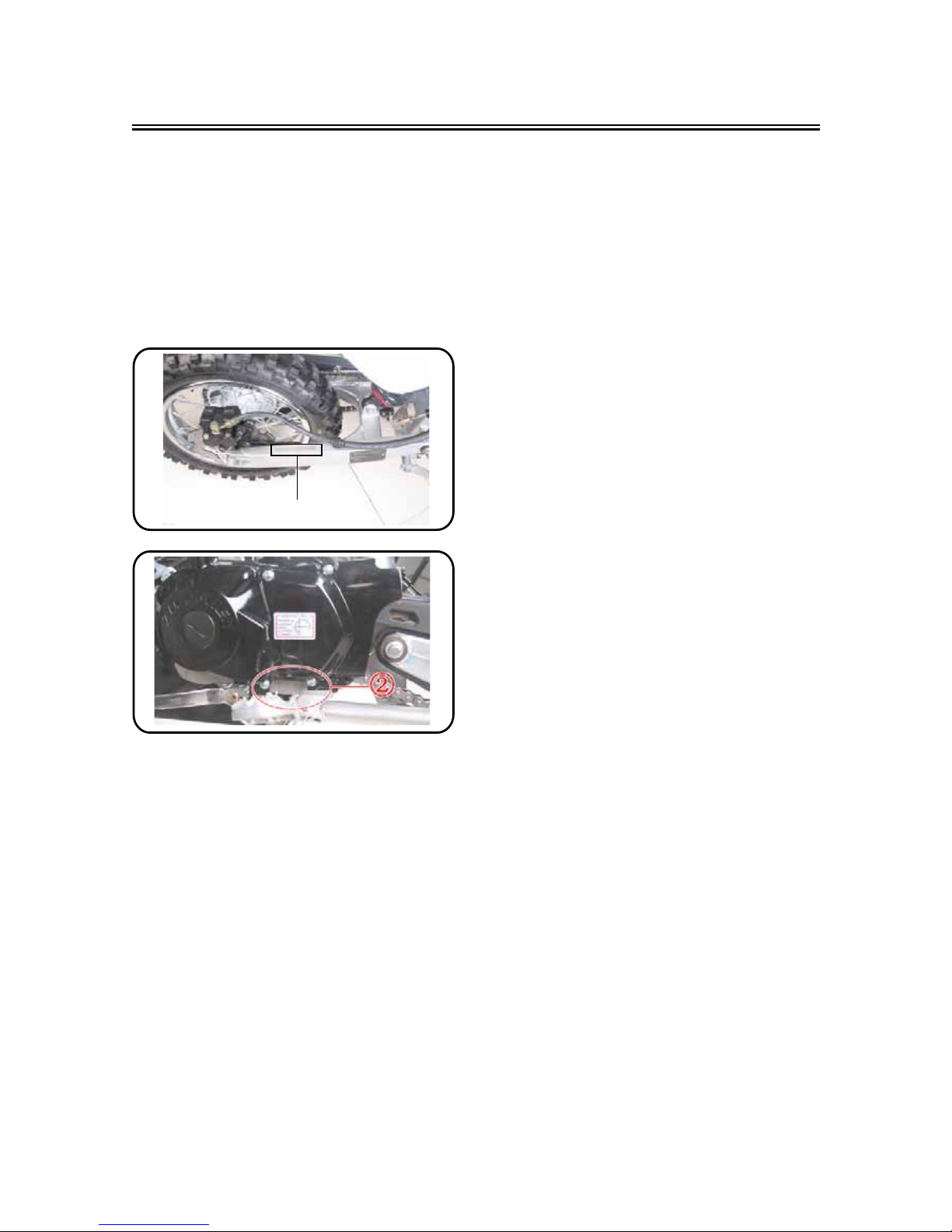
GASKETS, OIL SEALS AND O-RINGS
1. All gaskets, oil seals, and O-rings should
be replaced when an engine is overhauled. All gasket surfaces, oil seal lips,
and O-rings must be cleaned.
2. Properly oil all mating parts and bearings
during reassembly. Apply grease to the
oil seal lips.
LOCK WASHERS/PLATES AND COTTER
PINS
1. All lock washers/plates ① and cotter pins
must be replaced when they are
removed. Lock tab(s) should be bent
along the bolt or nut flat(s) after the bolt
or nut has been properly tightened.
BEARINGS AND OIL SEALS
1. Install the bearing(s) ① and oil seal(s) ②
with their manufacturer’s marks or numbers facing outward. (In other words, the
stamped letters must be on the side
exposed to view.) When installing oil
seal(s), apply a light coating of lightweight lithium base grease to the seal
lip(s). Oil the bearings liberally when
installing.
CAUTION:
Do not use compressed air to spin the
bearings dry. This causes damage to the
bearing surfaces.
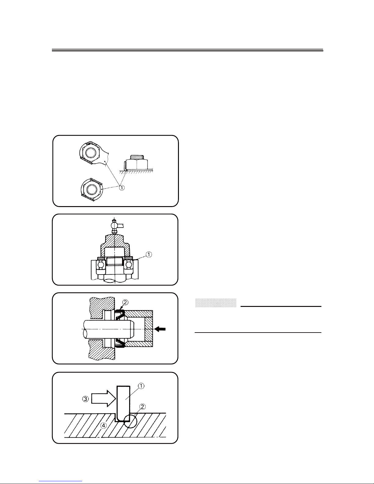
CIRCLIPS
1. All circlips should be inspected carefully
before reassembly. Always replace piston pin clips after one use. Replace distorted circlips. When installing a circlip
①, make sure that the sharp-edged cor-
ner ② is positioned opposite to the thrust
③ it receives. See the sectional view.
④ Shaft
Page 11
1 - 5
CHECKING OF CONNECTION
CHECKING OF CONNECTION
Dealing with stains, rust, moisture, etc. on the
connector.
1. Disconnect:
Connector
2. Dry each terminal with an air blower.
3. Connect and disconnect the connector
two or three times.
4. Pull the lead to check that it will not come
off.
5. If the terminal comes off, bend up the pin
① and reinsert the terminal into the con-
nector.
6. Connect:
Connector
NOTE:
The two connectors “click” together.
7. Check for continuity with a tester.
NOTE:
If there in no continuity, clean the terminals.
Be sure to perform the steps 1 to 7 listed
above when checking the wireharness.
For a field remedy, use a contact revitalizer
available on the market.
Use the tester on the connector as shown.
Page 12
1 - 6
SPECIAL TOOLS
SPECIAL TOOLS
The proper special tools are necessary for complete and accurate tune-up and assembly. Using the
correct special tool will help prevent damage caused by the use of improper tools or improvised
techniques. The shape and part number used for the special tool differ by country, so two types are
provided. Refer to the list provided to avoid errors when placing an order.
Tool name/How to us Illustration Tool name/How to us Illustration
Crankcase separating tool
These tool is used to remove the
crankshaft from either case.
Flywheel puller
This tool is used to remove the flywheel
magneto.
Rotor holding tool
This tool is used when loosening or
tightening the fly-wheel magneto
securing nut
Dial gauge and stand
Stand
These tools are used to check each part
for runout or bent.
Crankshaft installing tool/pot/bolt
Spacer (crankshaft installer)
Adapter (M12)
These tools are used to install the
crankshaft.
Piston pin puller set
This tool is used to remove the piston
pin.
Steering nut wrench
This tool is used when tighten the
steering ring nut to specification.
Pocket tester
Use this tool to inspect the coil
resistance, output voltage and amperage.
Valve spring compressor
This tool is needed to remove and
install the valve assemblies.
Clutch holding tool
This tool is used to hold the clutch
when removing or installing the clutch
boss securing nut.
Valve guide remover
This tool is needed to remove and
install the valve guide.
Page 13
1 - 7
CONTROL FUNCTIONS
CONTROL FUNCTIONS
ENGINE STOP SWITCH
The engine stop switch ① is located on the left
handlebar. Continue pushing the engine stop
switch till the engine comes to a stop.
CLUTCH LEVER
The clutch lever ② is located on the left han-
dlebar; it disengages or engages the clutch.
Pull the clutch lever to the handlebar to disengage the clutch, and release the lever to
engage the clutch. The lever should be pulled
rapidly and released slowly for smooth starts.
SHIFT PEDAL
The gear ratios of the constant-mesh 4 speed
transmission are ideally spaced. The gears
can be shifted by using the shift pedal ① on
the left side of the engine.
KICKSTARTER CRANK
Rotate the kickstarter crank ① away from the
engine. Push the starter down lightly with your
foot until the gears engage, then kick smoothly
and forcefully to start the engine. This model
has a primary kickstarter crank so the engine
can be started in any gear if the clutch is disengaged. In normal practices, however, shift to
neutral before starting.
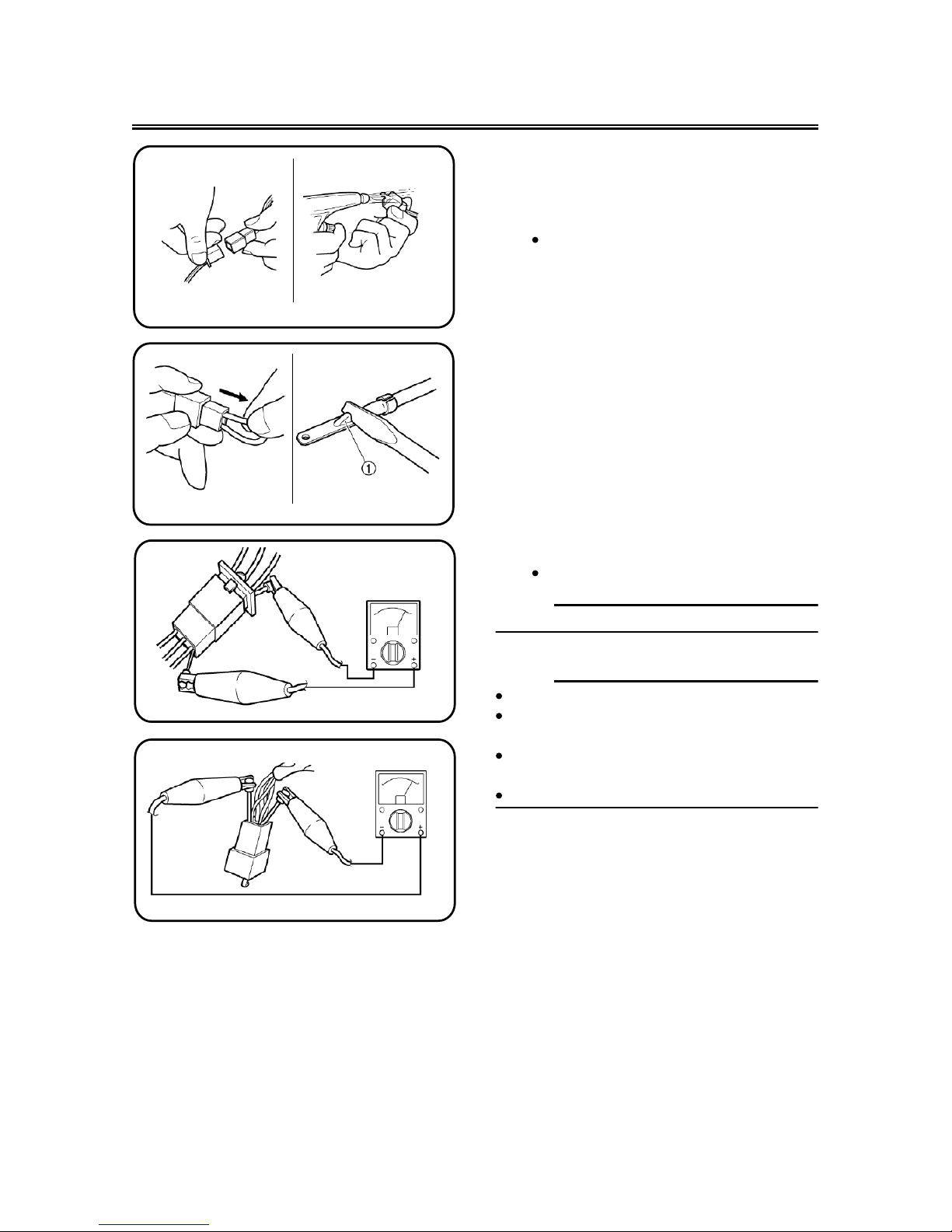
THROTTLE GRIP
The throttle grip ① is located on the right han-
dlebar; it accelerates or decelerates the
engine. For acceleration, turn the grip toward
you; for deceleration, turn it away from you.
Page 14
1 - 8
CONTROL FUNCTIONS
FRONT BRAKE LEVER
The front brake lever ① is located on the right
handlebar. Pull it toward the handlebar to activate the front brake.
REAR BRAKE PEDAL
The rear brake pedal ① is located on the right
side of the machine. Press down on the brake
pedal to activate the rear brake.
FUEL COCK
The fuel cock supplies fuel from the tank to
carburetor while filtering the fuel. The fuel cock
has the two positions:
OFF:With the lever in this position, fuel will not
flow. Always return the lever to this position when the engine is not running.
ON: With the lever in this position, fuel flows
to the carburetor. Normal riding is done
with the lever in this position
SPARK PLUG WRENCH
This spark plug wrench ① is used to remove
and install the spark plug.
NIPPLE WRENCH
This nipple wrench ① is used to tighten the
spoke.
①
NO
OFF
Page 15

2 - 1
SPECIFICATIONS
21G:emanledoM
:rebmunedocledoM
AGB-21G
Dimensions:
mm550,1,htgnelllarevO
mm006htdiwllarevO
mm038thgiehllarevO
mm096thgiehtaeS
mm501
,1esableehW
Minimum ground clearance 260 mm
Basic weight:
knatleufllufdnaliohtiW
Engine:
Air cooled 4-stroke epytenignE
denilcnidrawrof,rednilycelgniStnemegnarrarednilyC
m c3.6712t
nemecalpsiD
3
Bore s 0.54ekorts s 54 mm
1: 9oitarnoisserpmoC
retratskciKmetsysgnitratS
pmusyrD:metsysnoitacirbuL
Oil type or grade:
At 5 ˚C (40 ˚F) or higher
SF15W/40 type
SG motor oil
(Non-Friction modified)
At 15 ˚C (60 ˚F) or lower
2
2
GENERAL SPECIFICATIONS
66kg
and Electrical Starting
Page 16

2 - 2
GENERAL SPECIFICATIONS
Oil capacity:
Engine oil
L8.0egnahcliocidoireP
With oil filter replacement 0.85 L
L9.0tnuomalatoT
tnemeleepytteW:retlifriA
Fuel:
ahtiwylnoenilosagdedaelnumuimerPepyT
research octane number of 90 or higher.
Premium gasoline
L5.3yticapacknaT
Carburetor:
Z26-5KPepyT
rerutcafunaM
Spark plug:
A7RTC/NGK
rerutcafunam/epyT
mm7.0~6.0paG
csid-elpitlum,teW:epythctulC
Transmission:
Primary reduction system Gear
)277
.3(81/76oitarnoitcuderyramirP
Secondary reduction system Chain drive
Secondary reduction ratio 43/15 (2.867)
deeps-4,hsemtnatsnoCepytnoissimsnarT
noitarepotooftfeLnoitarepO
)818.2(11
/63ts1:oitarraeG
)839.1(61/13dn2
)053.1(02/72dr3
)340.1
(32/42ht4
Chassis:
eldarcelbuodimeSepytemarF
3.72elgnarets
aC˚
Tire:
ebuthtiWepyT
)tnorf(eziS
)raer(eziS
Tire pressure (front and rear) 130 kPa (1.3 kgf/cm
2
)
JINGKE
60/100-14 30M
80/100-12 41M
Page 17

2 - 3
GENERAL SPECIFICATIONS
Brake:
ekarbcsidelgniSepytekarbtnorF
noitarepodnahthgiRnoitarepO
ekarbcsidelgniSepytekarbraeR
noitarepotoofthg
iRnoitarepO
Suspension:
krofcipocseleTnoisnepsustnorF
)noisnepsusssorconomepytknil(mragniwSnoisnepsusraeR
Shock absorber:
repmadli
o/gnirpslioCrebrosbakcohstnorF
re
pm
a
dlio
/gnirpslioCrebrosbakcohsraeR
Wheel travel:
mm002levartleehwtnorF
mm002levartl
eehwraeR
Electrical:
otengamIDCmetsysnoitingI
Page 18
2 - 4
MAINTENANCE SPECIFICATIONS
ENGINE
timiLdradnatSmetI
Cylinder head:
mm30.0----timilpraW
Cylinder:
mm150.45~00.45eziseroB ----
mm50.0----timildnuorfotuO
Camshaft:
----)tfeL(evirdn
iahCdohtemevirD
Camshaft cap inside diameter
31.963 ~ 31.979 mm
----
Camshaft outside diameter
32.009 ~ 32.034 mm
----
mm071.0~030.0ecnaraelcpac-ot-tfahS
Cam dimensions
Intake “A” 26.555 ~ 26.675 mm 26.30 mm
“B” 20.99 ~ 21.01 mm 20.95 mm
Exhaust “A” 26.316 ~ 26.436 mm 26.00 mm
“B” 20.99 ~ 21.01 mm 20.95 mm
mm30.0----timiltuonurtfahsmaC
A
B
Page 19
2 - 5
MAINTENANCE SPECIFICATIONS
Timing chain:
Timing chain type / No. of links 90T/90 ----
----citamotuAdohtemtnemtsujdaniahcgnimiT
Valve, valve seat, valve guide:
Valve clearance (cold) IN 0.02 ~ 0.04 mm ----
EX 0.02 ~ 0.04 mm ----
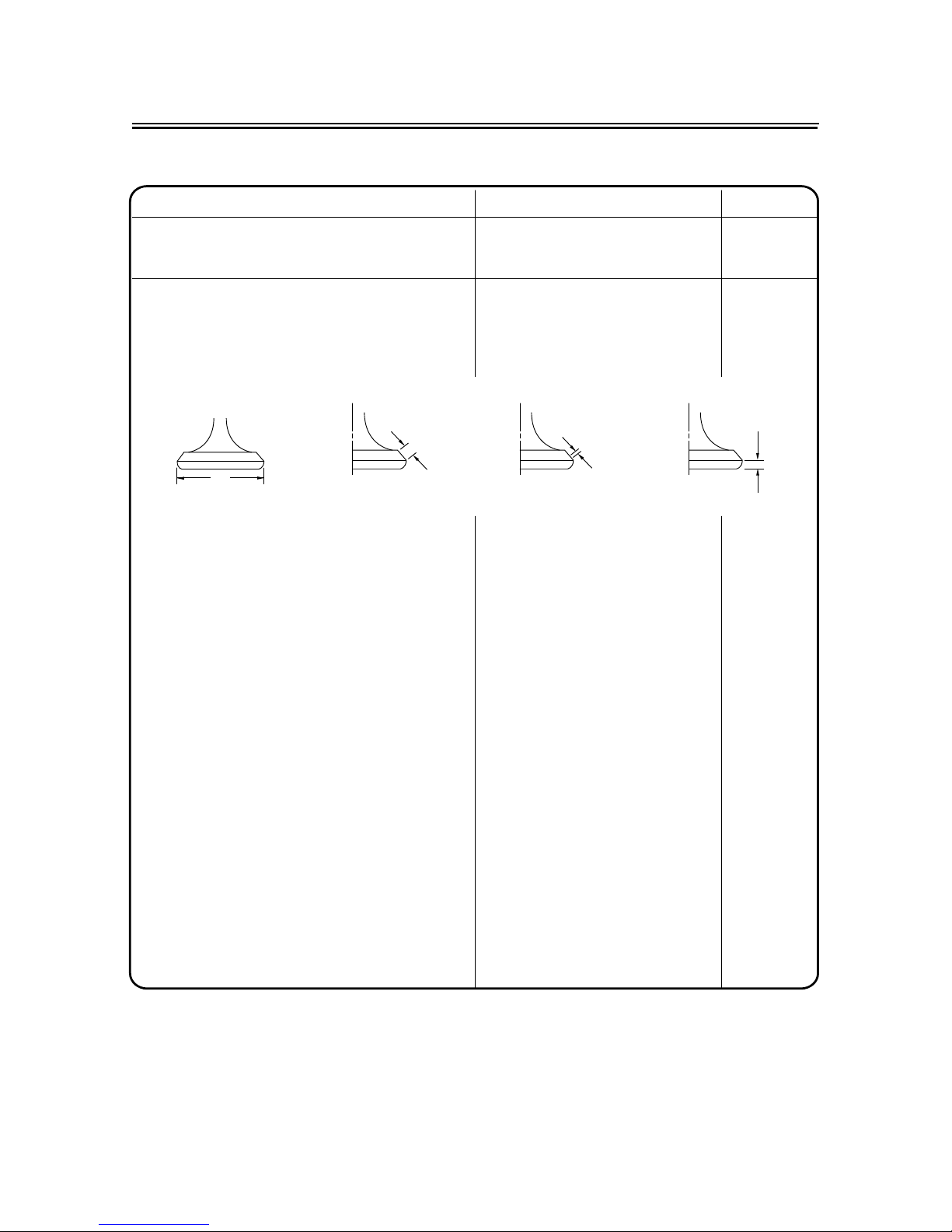
Valve dimensions:
“A” head diameter IN 26.9 ~ 27.1 mm ----
EX 22.9 ~ 23.1 mm ----
“B” face width IN 1.1~1.5 mm ----
EX 1.1~1.5 mm ----
“C” seat width IN 0.9 ~ 1.1 mm 1.6 mm
EX 0.8 ~ 1.0 mm 1.6 mm
“D” margin thickness IN 0.65~0.95 mm ----
EX 0.65~0.95 mm ----
Stem outside diameter IN 4.97~4.985 mm 4.94 mm
EX 4.955 ~ 4.97 mm 4.925 mm
Guide inside diameter IN 5.000 ~ 5.012 mm 5.050 mm
EX 5.500 ~ 5.512 mm 5.550 mm
Stem-to-guide clearance IN 0.015 ~ 0.042 mm 0.08 mm
EX 0.030 ~ 0.057 mm 0.10 mm
timiLdradnatSmetI
Head Diameter
B
Face Width
C
Seat Width
D
Margin Thickness
A
Page 20
2 - 6
MAINTENANCE SPECIFICATIONS
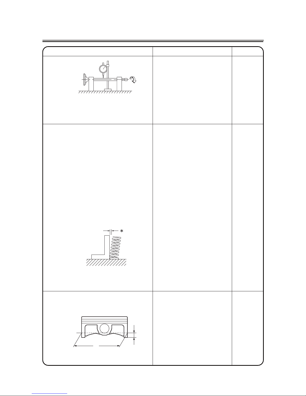
mm30.0----timiltuonurmetS
Valve seat width IN 0.8 ~ 1.2 mm 1.6 mm
EX 0.8 ~ 1.2 mm 1.6 mm
Valve spring:
mm5.23mm87.33NIhtgneleerF
EX 35.55 mm 34.0 mm
Set length (valve closed) IN 22.45 mm ----
EX 25.45 mm ----
Compressed force
mm54.22taN46~52NI)dellatsni( ----
EX 105 ~ 129 N at 25.45 mm ----
3.1----NItimilt
liT ˚/ 0.8 mm
35.1----XE ˚/0.8 mm
Direction of winding
----esiwkcolCNI)weivpot(
----esiwkcolCXE
Piston:
Piston to cylinder clearance 0.025 ~ 0.05 mm 0.1 mm
Piston size “D” 53.965 ~ 53.975 mm ----
Measuring point “H” 10 mm ----
----
edis-NI/
mm4.0tes-ffonotsiP
timiLdradnatSm
etI
H
D
Page 21
2 - 7
MAINTENANCE SPECIFICATIONS
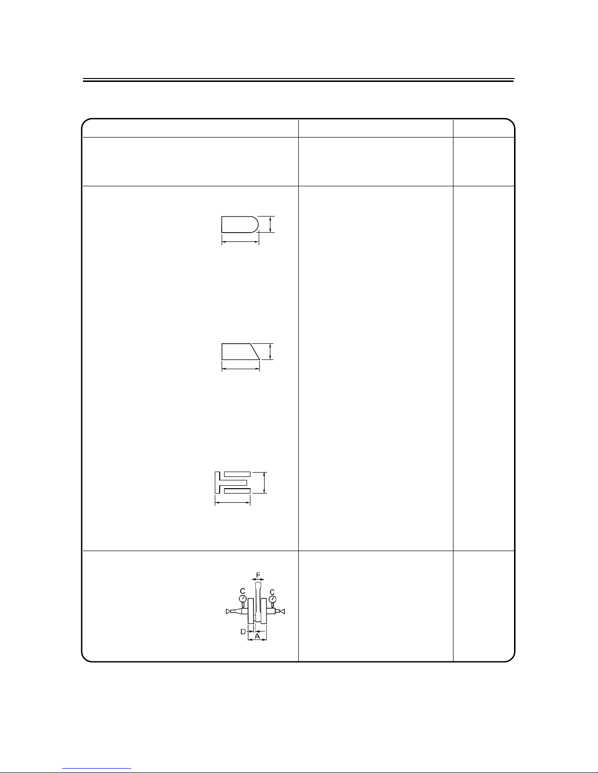
Piston pin bore inside diameter 14.002 ~ 14.013 mm 14.04 mm
Piston pin outside diameter 13.994 ~ 14.000 mm 13.98 mm
Piston rings:
Top ring:
----lerraBepyT
Dimensions (B s .980)T s 2.00mm ----
mm52.0~01.0)dellatsni(pagdnE 0.60 mm
Side clearance (installed) 0.040 ~ 0.080 mm 0.12 mm
2nd ring:
----repaTepyT
Dimensions (B s 98.0)T s 2.20 mm ----
mm03.0~51.0)dellatsni(
pagdnE 0.60 mm
mm080.0~040.0ecnaraelcediS 0.12 mm
Oil ring:
Dimensions (B s 29.1)T s 2.45 mm ----
mm05.0~02.0)dellatsni(pagdnE ----
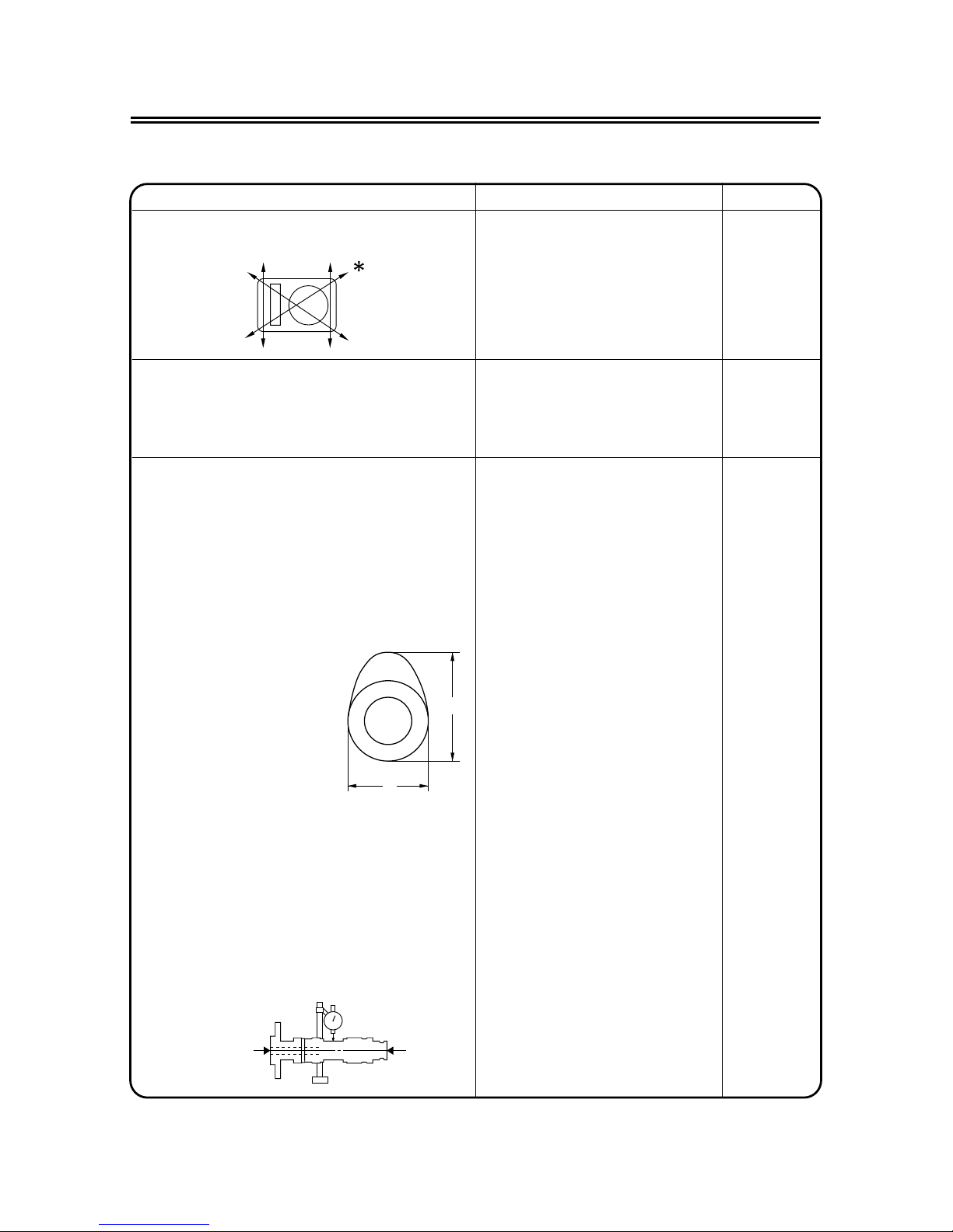
Crankshaft:
Crank width “A” 40.15~ 40.20 mm ----
Runout limit “C” 0.03 mm 0.05 mm
Big end side clearance “D” 0.15 ~ 0.35mm 0.60 mm
Small end free play “F” 0.4 ~ 1.0 mm 2.0 mm
timiLdradnatSmetI
7
%
B
T
B
T
Page 22

2 - 8
MAINTENANCE SPECIFICATIONS
Clutch:
mm95.2~85.2ssenkcihtetalpnoitcirF 2.7 mm
----3ytitnauQ
----mm6.1~4.1ssenkcihtetalphctulC
----3ytitnauQ
mm1.0----t
imilpraW
mm5.91mm5.02htgneleerfgnirpshctulC
----4ytitnauQ
----
----
----hsupmac,hsuprennIdohtemesaelerhctulC
Shifter:
---
-rabediugdnamurdmaCepytretfihS
mm50.0----timilgnidnebrabediuG
Kickstarter:
----epyttehctardnakciKepyT
:roterubraC
/Z26-5KP
rerutcafunam/epyT
JINGKE
¾
----KJkram.D.I
#58)J.M(tejniaM ¾ ----
)J.A.M(tejrianiaM ø1.0 ¾
¾
----
----26-5
38#
ø2.0
8 g
2.0 ~ 3.0 mm
)N.J(eldeenteJ
)
I.J(Idle jet
Float needle valve size (F.N.A)
Float weight (F.W)
Float height (F.H)
¾ ---¾ ---¾ ---¾ ----
Air throttle (A.T) B6L ¾ ----
timiLdradnatSmetI
Page 23

3 - 1
MAINTENANCE INTERVALS
REGULAR INSPECTION AND ADJUSTMENTS
MAINTENANCE INTERVALS
The following schedule is intended as a general guide to maintenance and lubrication. Bear in mind
that such factors as weather, terrain, geographical location, and individual usage will alter the
required maintenance and lubrication intervals. If you are a doubt as to what intervals to follow in
maintaining and lubricating your machine, consult your dealer.
Item
After
break-in
Every
race
Every
third
(or
500 km)
Every
fifth
(or
1,000 km)
As required
Remarks
ENGINE OIL
Replace
Inspect
ƽ
ƽ
ƽ
ƽ
OIL FILTER ELEMENT, OIL STRAINER
Clean
ƽ
VALVES
Check the valve clearances
Inspect
Replace
ƽ
ƽ
ƽ
ƽ
The engine must be cold.
Check the valve seats
and valve stems for wear.
VALVE SPRINGS
Inspect
Replace
ƽ
ƽ
Check the free length and
the tilt.
VALVE LIFTERS
Inspect
Replace
ƽ
ƽ
Check for scratches and
wear.
CAMSHAFTS
Inspect
Replace
ƽ
ƽ
Inspect the camshaft surface.
Inspect the decompres-
sion system.
TIMING CHAIN SPROCKETS, TIMING
CHAIN
Inspect
Replace
ƽ
ƽ
Check for wear on the
teeth and for damage.
PISTON
Inspect
Clean
Replace
ƽ
ƽ
ƽ
ƽ
Inspect crack
Inspect carbon deposits
and eliminate them.
PISTON RING
Inspect
Replace
ƽ
ƽ
ƽ
Check ring end gap
PISTON PIN
Inspect
Replace
ƽ
ƽ
CYLINDER HEAD
Inspect and clean
ƽ
Inspect carbon deposits
and eliminate them.
Change gasket
CYLINDER
Inspect and clean
Replace
ƽ
ƽ
Inspect score marks
Inspect wear
CLUTCH
Inspect and adjust
Replace
ƽ
ƽ
ƽ
Inspect housing, friction
plate, clutch plate and
spring
TRANSMISSION
Inspect
Replace bearing
ƽ
ƽ
Page 24

3 - 2
MAINTENANCE INTERVALS
SHIFT FORK, SHIFT CAM, GUIDE BAR
Inspect
ƽ
Inspect wear
ROTOR NUT
Retighten
ƽ
ƽ
EXHAUST PIPE, SILENCER, PROTECTOR
Inspect and retighten
Clean
Replace
ƽ
ƽ
ƽ
ƽ
* Whichever comes first
CRANK
Inspect and clean
ƽ
ƽ
CARBURETOR
Inspect, adjust and clean
ƽ
ƽ
When using a high-pres-
sure washer, make sure
that water does not enter
the accelerator pump.
SPARK PLUG
Inspect and clean
Replace
ƽ
ƽ
ƽ
DRIVE CHAIN
Lubricate, slack, alignment
Replace
ƽ
ƽ
ƽ
Use chain lube
Chain slack: 30 ~ 40 mm
OUTSIDE NUTS AND BOLTS
Retighten
ƽ
ƽ
Refer to “STARTING
AND BREAK-IN” section
in the CHAPTER 1.
AIR FILTER
Clean and lubricate
Replace
ƽ
ƽ
ƽ
Use foam air-filter oil or
equivalent oil
OIL FILTER
Replace
ƽƽ
OIL STRAINER (frame)
Clean
ƽ
FRAME
Clean and inspect
ƽ
ƽ
FUEL TANK, COCK
Clean and inspect
ƽ
ƽ
BRAKES
Adjust lever position and pedal height
Lubricate pivot point
Check brake disc surface
Check fluid level and leakage
Retighten brake disc bolts, caliper
bolts, master cylinder bolts and union
bolts
Replace pads
Replace brake fluid
ƽ
ƽ
ƽ
ƽ
ƽ
ƽ
ƽ
ƽ
ƽ
ƽ
ƽ
ƽ
Every one year
Item
After
break-in
Every
race
Every
third
(or
500 km)
Every
fifth
(or
1,000 km)
As required
Remarks
Page 25

3 - 3
MAINTENANCE INTERVALS
FRONT FORKS
Inspect and adjust
Replace oil
Replace oil seal
ƽ
ƽ
ƽ
ƽ
ƽ
FRONT FORK OIL SEAL AND DUST
SEAL
Clean and lube
ƽ
ƽ
esaerg esab muihtiL
REAR SHOCK ABSORBER
Inspect and adjust
Lube
Retighten
ƽ
ƽ
ƽ
ƽ
ƽ
(After
rain ride)
ƽ
Molybdenum disulfide
grease
DRIVE CHAIN GUIDE AND ROLLERS
Inspect
ƽ
ƽ
SWINGARM
Inspect, lube and retighten
ƽ ƽ
Molybdenum disulfide
grease
RELAY ARM, CONNECTING ROD
Inspect, lube and retighten
ƽ ƽ
Molybdenum disulfide
grease
STEERING HEAD
Inspect free play and retighten
Clean and lube
Replace bearing
ƽ ƽ
ƽ
ƽ
Lithium base grease
TIRE, WHEELS
Inspect air pressure, wheel run-out,
tire wear and spoke looseness
Retighten sprocket bolt
Inspect bearings
Replace bearings
Lubricate
ƽ
ƽ
ƽ
ƽ
ƽ
ƽ
ƽ
Lithium base grease
THROTTLE, CONTROL CABLE
Check routing and connection
Lubricate
Inspect and clean (throttle cable)
ƽ
ƽ
ƽ
ƽ
ƽ
ƽ
SAE 10W-30 motor oil
Inspect dirt and wear on
the throttle cable on the
carburetor side.
Item
After
break-in
Every
race
Every
third
(or
500 km)
Every
fifth
(or
1,000 km)
As required
Remarks
Page 26

3 - 4
PRE-OPERATION INSPECTION AND MAINTENANCE
PRE-OPERATION INSPECTION AND MAINTENANCE
Before riding for break-in operation, practice or a race, make sure the machine is in good operating
condition.
Before using this machine, check the following points.
GENERAL INSPECTION AND MAINTENANCE
enituoRmetI
Fuel
Check that a fresh gasoline is filled in the fuel tank. Check the
fuel line for leakage.
Engine oil
Check that the oil level is correct. Check the crankcase and
frame oil line for leakage.
Gear shifter and clutch
Check that gears can be shifted correctly in order and that the
clutch operates smoothly.
Throttle grip/Housing
Check that the throttle grip operation and free play are correctly
adjusted. Lubricate the throttle grip and housing, if necessary.
.ekarb raer dna tnorf fo tceffe dna ekarb tnorf fo yalp eht kcehCsekarB
Drive chain
Check drive chain slack and alignment. Check that the drive
chain is lubricated properly.
Wheels
Check for excessive wear and tire pressure. Check for loose
spokes and have no excessive play.
Steering
Check that the handlebar can be turned smoothly and have no
excessive play.
Front forks and rear shock
absorber
Check that they operate smoothly and there is no oil leakage.
Cables (wires)
Check that the clutch and throttle cables move smoothly. Check
that they are not caught when the handlebars are turned or
when the front forks travel up and down.
Exhaust pipe
Check that the exhaust pipe is tightly mounted and has no
cracks.
Rear wheel sprocket Check that the rear wheel sprocket tightening bolt is not loose.
Lubrication Check for smooth operation. Lubricate if necessary.
Bolts and nuts Check the chassis and engine for loose bolts and nuts.
Lead connectors
Check that the CDI magneto, CDI unit, and ignition coil are con-
nected tightly.
Page 27
3 - 5
CLUTCH ADJUSTMENT
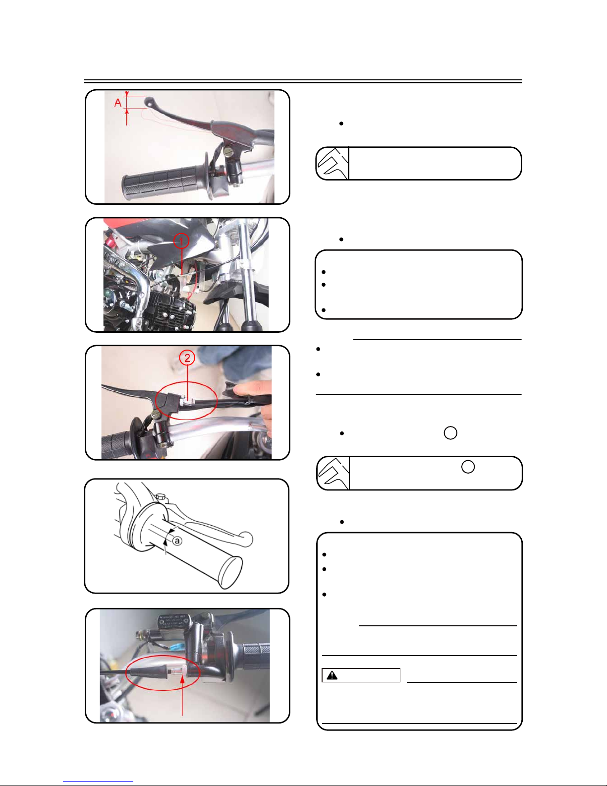
CLUTCH ADJUSTMENT
1. Check:
Clutch lever free play $
Out of specification m Adjust.
Clutch lever free play $ :
5 ~ 10 mm
2. Adjust:
Clutch lever free play
NOTE:
Make minute adjustment on the lever side
using the adjuster ② .
After adjustment, check proper operation of
clutch lever.
Clutch lever free play adjustment steps:
Loosen the locknuts ① .
Adjust the free play by changing their
tightening position.
Tighten the locknuts.
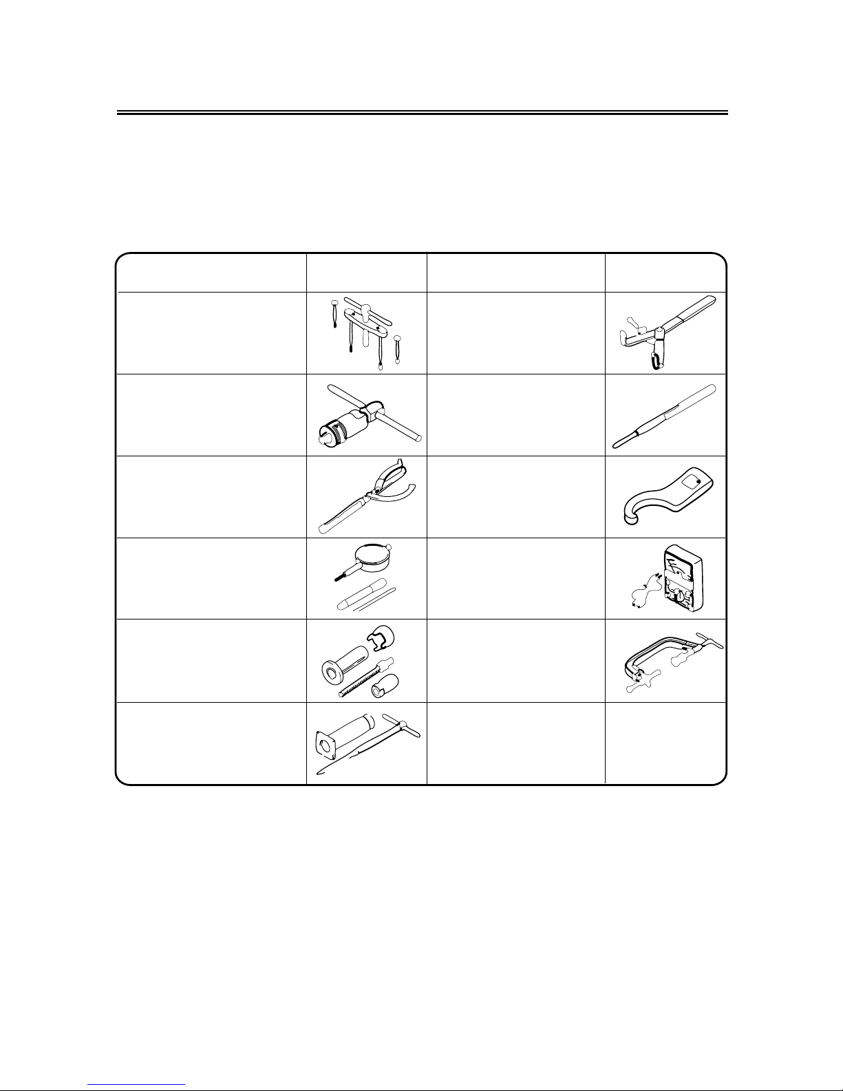
THROTTLE CABLE ADJUSTMENT
1. Check:
Throttle grip free play a
Out of specification m Adjust.
Throttle grip free play a :
3 ~ 5 mm
2. Adjust:
Throttle grip free play
Throttle grip free play adjustment steps:
Slide the adjuster cover.
Turn the adjuster ① until the specified free
play is obtained.
Tighten the locknut.
NOTE:
Before adjusting the throttle cable free play,
the engine idle speed should be adjusted.
WARNING
After adjusting, turn the handlebar to
right and left and make sure that the
engine idling does not run faster.
①
Page 28
3 - 6
THROTTLE CABLE ADJUSTMENT/
THROTTLE LUBRICATION
THROTTLE LUBRICATION
1. Remove:
Screw (throttle grip cap)
2. Apply:
Lithium soap base grease
On the throttle cable end
3. Install:
Screw (throttle grip cap)
T
R
.
.
4 Nm (0.4 m · kg)
AIR FILTER REPLACE
NOTE:
Proper air filter maintenance is the biggest key
to preventing premature engine wear and
damage.
CAUTION:
Never run the engine without the air filter
element in place; this would allow dirt and
dust to enter the engine and cause rapid
wear and possible engine damage.
1. Remove:
Screw
Page 29
3 - 7
2. Install:
T
R
.
.
5 Nm (0.5 m · kg)
ENGINE OIL LEVEL INSPECTION
1. Start the engine, warm it up for several
minutes, and then turn off the engine and
wait for five minutes.
2. Place the machine on a level place and
hold it up on upright position by placing
the suitable stand under the engine.
3. Remove:
Oil tank cap ①
ENGINE OIL LEVEL INSPECTION
Fitting Screw
Page 30
3 - 8
ENGINE OIL LEVEL INSPECTION
CAUTION:
Do not add any chemical additives or use
oils with a grade of CD D or higher.
Do not use oils labeled “ENERGY CONSERVING II” E or higher. Engine oil also
lubricates the clutch and additives could
cause clutch slippage.
Do not allow foreign materials to enter the
crankcase.
5. Install:
Oil tank cap
6. Start the engine and let it warm up for
several minutes.
7. Turn off the engine and inspect the oil
level once again.
NOTE:
Wait a few minutes until the oil settles before
inspecting the oil level.
Recommended oil:
Refer to the following chart for
selection of oils which are suited
to the atmospheric temperatures.
Recommended engine oil classification:
API STANDARD:
API “SG” or higher grade
(Designed primarily for motor-
cycles)
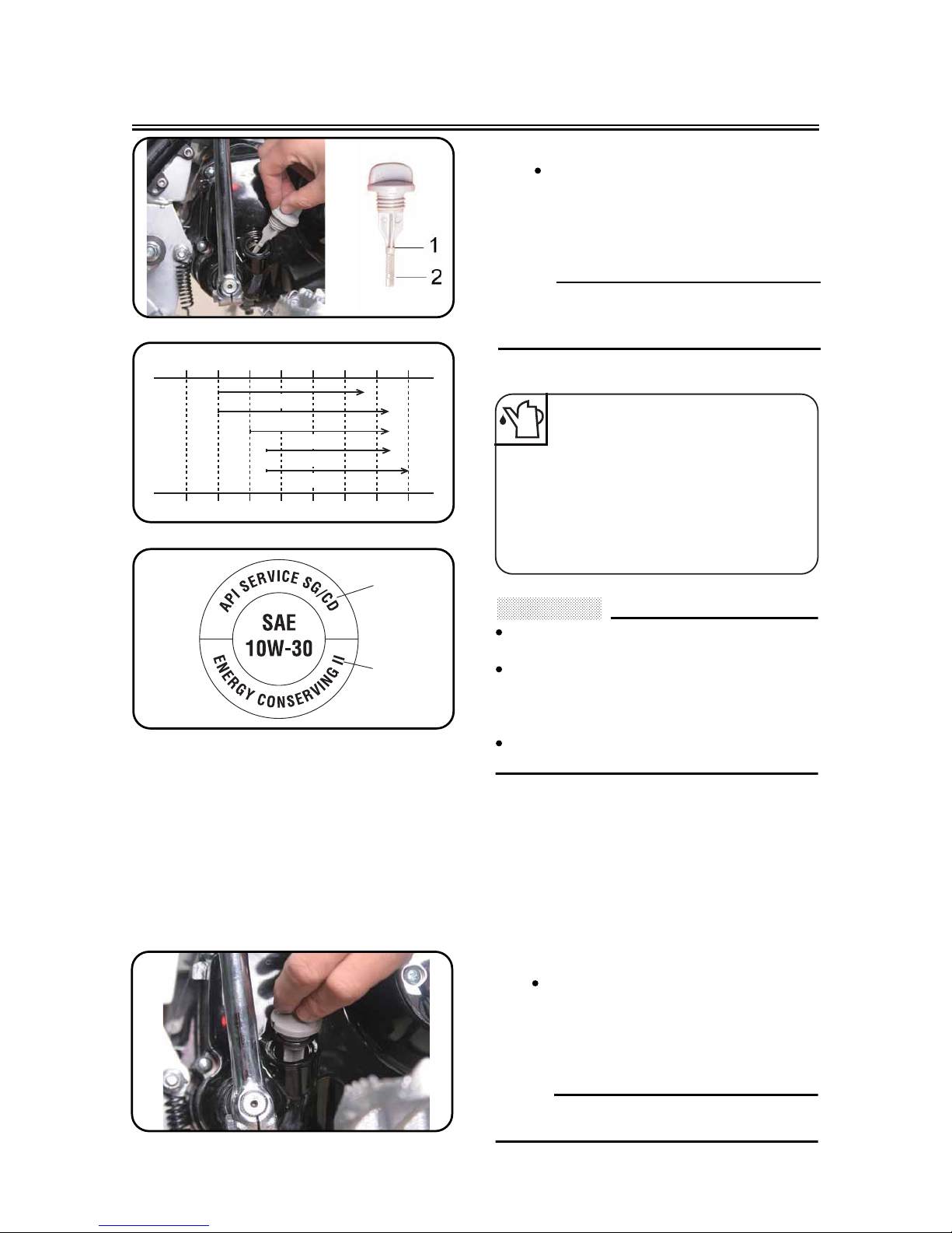
4. Inspect:
Oil level
Oil level should be between maximum
and minimum marks.
Oil level is low m Add oil to proper
level.
NOTE:
When inspecting the oil level, do not screw the
oil tank cap into the oil tank. Insert the gauge
lightly.
-20-4-101403010502068308640 50
104
122
oCTemp.
oF
10W-30
10W-40
20W-40
20W-50
15W-40
D
E
Page 31

3 - 9
ENGINE OIL REPLACEMENT
ENGINE OIL REPLACEMENT
1. Start the engine and warm it up for several minutes, and then turn off the engine
and wait for five minute.
2. Place the machine on a level place and
hold it on upright position by placing the
suitable stand under the engine.
3. Place a suitable container under the
engine.
4. Remove:
Oil cap
5. Fill:
Engine oil
6. Check:
Oil leakage
7. Check:
Engine oil level
Oil quantity:
Total amount:
0.9 L
Periodic oil change:
0.8 L
With oil filter replacement:
0.85 L
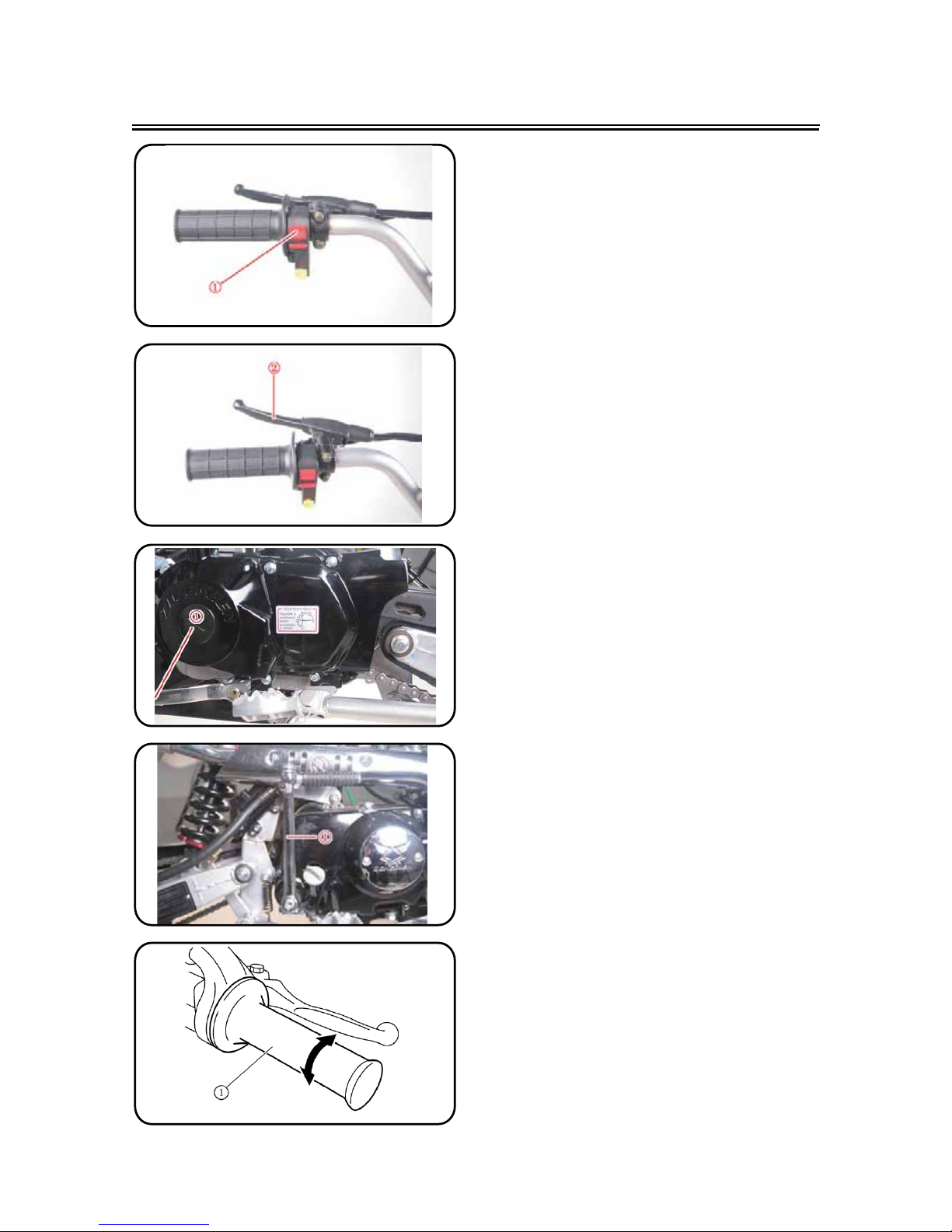
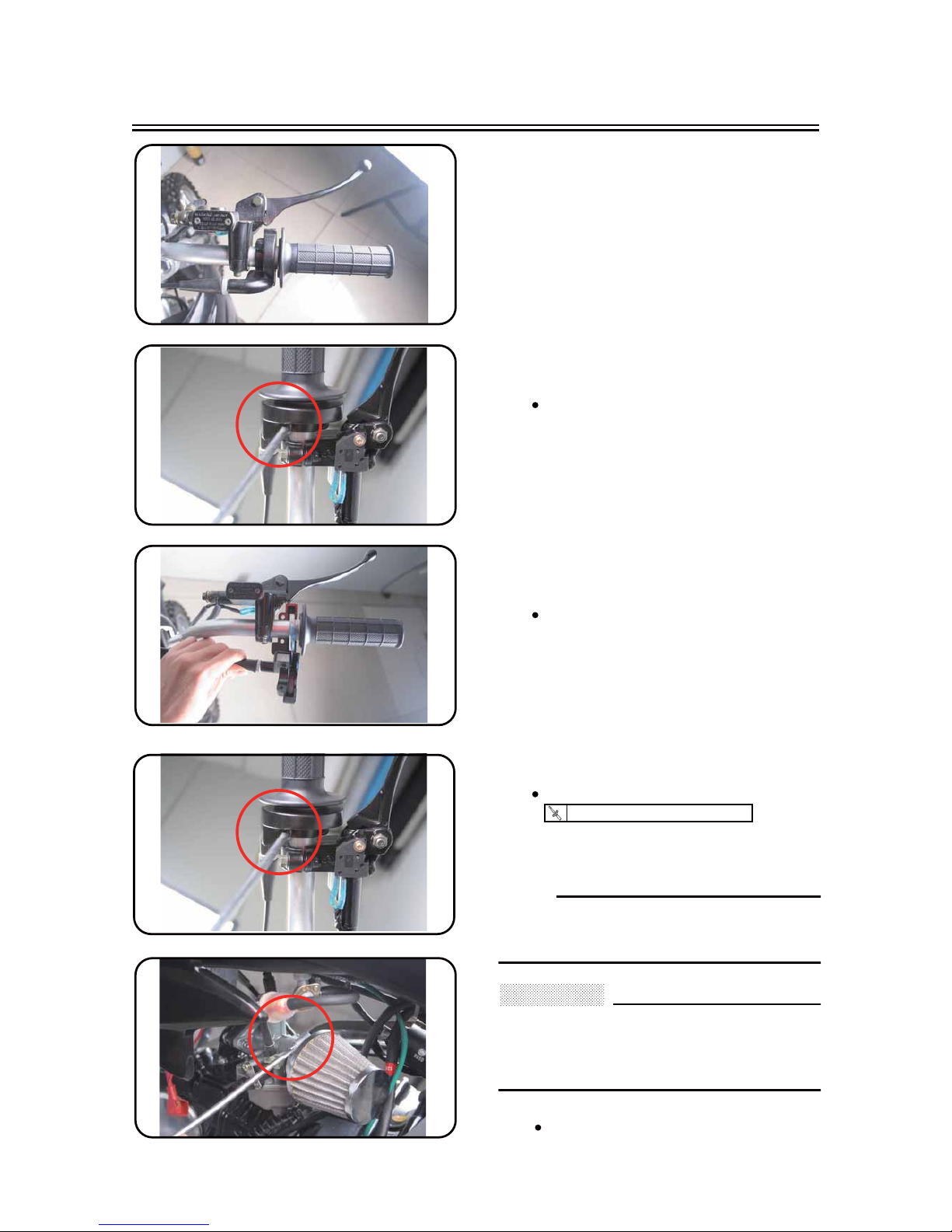
OIL PRESSURE INSPECTION
1. Check:
Oil pressure
Checking steps:
Slightly loosen the oil pressure check bolt
.
Start the engine and keep it idling until oil
starts to seep from the oil pressure check
bolt. If no oil comes out after one minute,
turn the engine off so it will not seize.
Check oil passages and oil pump for damage or leakage.
Start the engine after solving the problem(s) and recheck the oil pressure.
Tighten the oil pressure check bolt.
T
R
.
.
Oil pressure check bolt:
10 Nm (1.0 m • kg)
①
①
a
Page 32

3 - 10
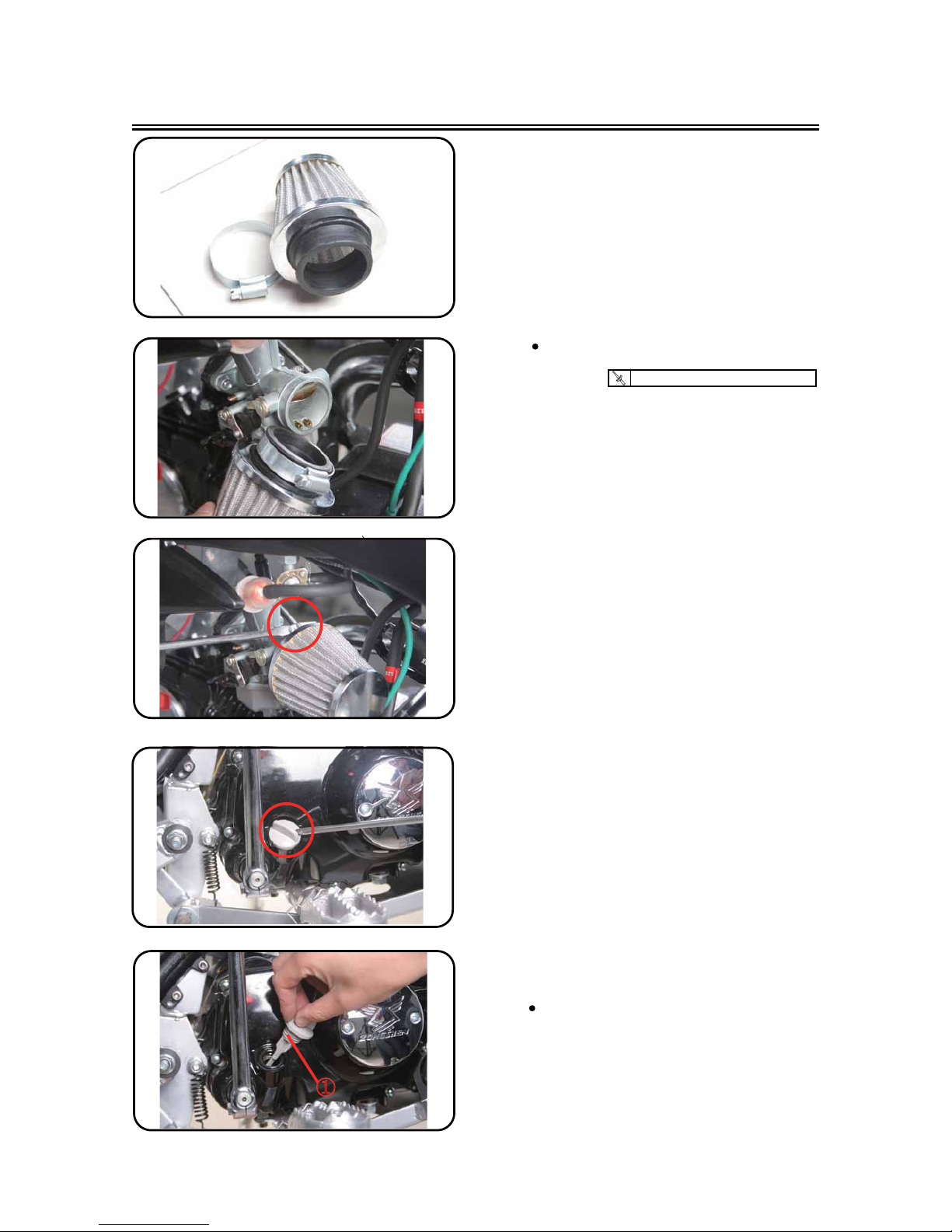
PILOT SCREW ADJUSTMENT
1. Adjust:
Pilot screw ①
Adjustment steps:
NOTE:
To optimize the fuel flow at a smaller throttle
opening, each machine’s pilot screw has
been individually set at the factory. Before
adjusting the pilot screw, turn it in fully and
count the number of turns. Record this number as the factory-set number of turns out.
Turn in the pilot screw until it is lightly
seated.
Turn out the pilot screw by the factory-set
number of turns.
Pilot screw:
1-5/8 turns out (example)
PILOT SCREW ADJUSTMENT
ENGINE IDLING SPEED ADJUSTMENT
1. Start the engine and thoroughly warm it
up.
2. Attach:
Inductive tachometer
To spark plug lead.
3. Adjust:
Engine idling speed
Adjustment steps:
Adjust the pilot screw.
Refer to “PILOT SCREW ADJUSTMENT”
section.
Turn the throttle stop screw ① until the
engine runs at the lowest possible speed.
To increase idle speed m Turn the throt-
tle stop screw ① in .
To decrease idle speed m Turn the throt-
tle stop screw ① out B .
Engine idling speed:
1,400 ~ 1,600 r/min
A
ENGINE IDLING SPEED ADJUSTMENT
Page 33

3 - 11
CHASSIS/BRAKE SYSTEM AIR BLEEDING
CHASSIS
BRAKE SYSTEM AIR BLEEDING
Bleed the brake system if:
The system has been disassembled.
A brake hose has been loosened or
removed.
The brake fluid is very low.
The brake operation is faulty.
A dangerous loss of braking performance
may occur if the brake system is not properly bleed.
1. Remove:
Reservoir cap
Diaphragm
2. Bleed:
Brake fluid
Front
Rear
Air bleeding steps:
a. Add proper brake fluid to the reservoir.
b. Install the diaphragm. Be careful not to
spill any fluid or allow the reservoir to
overflow.
c. Connect the clear plastic tube ② tightly
to the caliper bleed screw ① .
d. Place the other end of the tube into a
container.
e. Slowly apply the brake lever or pedal
several times.
f. Pull the lever in or push down on the
pedal. Hold the lever or pedal in position.
g. Loosen the bleed screw and allow the
lever or pedal to travel towards its limit.
h. Tighten the bleed screw when the lever
or pedal limit has been reached; then
release the lever or pedal.
T
R
.
.
Bleed screw:
6 Nm (0.6 m • kg)
i. Repeat steps (e) to (h) until of the air
bubbles have been removed from the
system.
B
A
B
A
WARNING
①
②
①
②
Page 34

3 - 12
FRONT BRAKE ADJUSTMENT
3. Install:
Diaphragm
Reservoir cap
If bleeding is difficult, it may be necessary to
let the brake fluid system stabilize for a few
hours. Repeat the bleeding procedure when
the tiny bubbles in the system have disappeared.
j. Add brake fluid to the level line on the
reservoir.
Check the operation of the brake after
bleeding the brake system.
FRONT BRAKE
1. Check:
Brake lever position A
Brake lever position A :
Standard position Extent of adjustment
100 mm
Unavailable
REAR BRAKE ADJUSTMENT
REAR BRAKE ADJUSTMENT
1. Check:
Brake pedal height A
Out of specification m Adjust.
Brake pedal height A :
10 mm
2. Adjust:
Brake pedal height
Pedal height adjustment steps:
Loosen the locknut ① .
Turn the adjusting nut ② until the pedal
height D is within specified height.
Tighten the locknut.
Adjust the pedal height between the
maximum and the minimum
After the pedal height adjustment, make
sure that the rear brake does not drag.
WARNING
NOTE:
WARNING
Page 35

3 - 13
FRONT BRAKE PAD INSPECTION AND REPLACEMENT
FRONT BRAKE PAD INSPECTION AND
REPLACEMENT
1. Inspect:
Brake pad thickness A
Out of specification m Replace as a
set.
2. Replace:
Brake pad
Brake pad thickness:
4.0 mm
<Limit>: 1.0 mm
Brake pad replacement steps:
Remove Bolt 1 and 2
Loosen the Caliper
CAUTION:
Do not reuse the drained brake fluid.
Tighten the bleed screw.
T
R
.
.
Bleed screw 3 and 4 :
18 Nm (1.8 m • kg)
Install the Caliper Bolt 1 and 2
T
R
.
.
Bolt (brake caliper):
25 Nm (2.5 m • kg)
Remove Bolt 3 and 4
Replace the Brake pad
3. Inspect:
Brake fluid level
Refer to “BRAKE FLUID LEVEL
INSPECTION” section.
4. Check:
Brake lever operation
A softy or spongy feeling m Bleed
brake system.
Refer to “BRAKE SYSTEM AIR
BLEEDING” section.
Page 36

3 - 14
REAR BRAKE PAD INSPECTION AND REPLACEMENT
REAR BRAKE PAD INSPECTION AND
REPLACEMENT
1. Inspect:
Brake pad thickness A
Out of specification m Replace as a
set.
2. Replace:
Brake pad
Brake pad thickness:
4 mm
<Limit>: 1.0 mm
Brake pad replacement steps:
Remove the Screw 1 and 2.
Loosen the Caliper
Remove the Nut 3.
.
Reeplace the Brake pad.
Page 37

3 - 15
REAR BRAKE PAD INSPECTION AND REPLACEMENT
CAUTION:
Do not reuse the drained brake fluid.
Tighten the bleed screw 1 and 2.
T
R
.
.
Bleed screw 1 and 2:
18 Nm (1.8m kg)
T
R
.
.
Nut 3 (brake caliper):
20 Nm (2.0m kg)
3. Inspect:
Brake fluid level
Refer to “BRAKE FLUID LEVEL
INSPECTION” section.
4. Check:
Brake pedal operation
A softy or spongy feeling m Bleed
brake system.
Refer to “BRAKE SYSTEM AIR
BLEEDING” section.
BRAKE FLUID LEVEL INSPECTION
1. Place the brake master cylinder so that
its top is in a horizontal position.
2. Inspect:
Brake fluid level
Fluid at lower level m Fill up.
D Lower level
A Front
B Rear
Use only designated quality brake fluid to
avoid poor brake performance.
Refill with same type and brand of brake
fluid; mixing fluids could result in poor
brake performance.
Be sure that water or other contaminants
do not enter master cylinder when refilling.
Clean up spilled fluid immediately to
avoid erosion of painted surfaces or plastic parts.
Recommended brake fluid:
DOT #3 or DOT #4
A
B
WARNING
Page 38

3 - 16
SPROCKETS INSPECTION/DRIVE CHAIN INSPECTION
SPROCKETS INSPECTION
1. Inspect:
Sprocket teeth a
Excessive wear m Replace.
NOTE:
Replace the drive sprocket, rear wheel
sprocket and drive chain as a set.
DRIVE CHAIN INSPECTION
1. Remove:
Master link clip
Joint
Drive chain
2. Clean:
Drive chain
Place it in kerosene, and brush off as
much dirt as possible. Then remove the
drive chain from the kerosene and dry
the drive chain.
3. Measure:
Drive chain length (10 links) a
Out of specification m Replace.
Drive chain length (10 links):
<Limit>: 144.4 mm
4. Check:
Drive chain stiffness a
Clean and oil the drive chain and hold
as illustrated.
Stiff m Replace drive chain.
Page 39

3 - 17
DRIVE CHAIN SLACK ADJUSTMENT
5. Install:
Drive chain
Joint
Master link clip
CAUTION:
Be sure to install the master link clip to the
direction as shown.
Turning direction
6. Lubricate:
Drive chain
Drive chain lubricant:
SAE 10W-30 motor oil or suitable chain lubricants
DRIVE CHAIN SLACK ADJUSTMENT
1. Elevate the rear wheel by placing the
suitable stand under the engine.
2. Check:
Drive chain slack A
Above the seal guard installation bolt.
Out of specification m Adjust.
NOTE:
Before checking or adjusting, rotate the
rear wheel through several revolutions and
check the slack several times to find the tightest point. Check and/or adjust the drive chain
slack with the rear wheel in this “tight chain”
position.
Drive chain slack:
30 ~ 50 mm
ķ
ĸ
Ĺ
A
A
Page 40

3 - 18
FRONT FORK INSPECTION
3. Adjust:
Drive chain slack
Drive chain slack adjustment steps:
Loosen the axle nut ① and locknuts ② .
Adjust the drive chain slack by turning the
adjusters ③ .
To tighten m Turn the adjuster ③ coun-
terclockwise.
To loosen m Turn the adjuster ③ clock-
wise and push wheel forward.
Turn each adjuster exactly the same
amount to maintain correct axle alignment.
NOTE:
Turn the adjuster so that the drive chain is in
line with the sprocket, as viewed from the
rear.
CAUTION:
Too small drive chain slack will overload
the engine and other vital parts; keep the
slack within the specified limits.
Tighten the axle nut while pushing down
the drive chain.
T
R
.
.
Axle nut:
65 Nm (6.5 m • kg)
Tighten the locknuts.
T
R
.
.
Locknut:
12 Nm (1.2 m
FRONT FORK INSPECTION
1. Inspect:
Front fork smooth action
Operate the front brake and stroke the
front fork.
Unsmooth action/oil leakage m Repair
or replace.
• kg)
Page 41

3-19
CHECKING THE BATTERY
CAUTION:
ELECTRICAL SYSTEM
CHECKING THE BATTERY
Batteries generate explosive hydrogen gas
and contain electrolyte which is made of
poisonous and highly caustic sulfuric acid.
Therefore, always follow these preventive
measures:
Wear protective eye gear when handling or
working near batteries.
Charge batteries in a well-ventilated area.
Keep batteries away from fire, sparks or
open flames (e.g., welding equipment,
lighted cigarettes).
DO NOT SMOKE when charging or handling batteries.
KEEP BATTERIES AND ELECTROLYTE
OUT OF REACH OF CHILDREN.
Avoid bodily contact with electrolyte as it
can cause severe burns or permanent eye
injury.
First aid in case of bodily contact:
External
SKIN – Wash with water.
EYES – Flush with water for 15 minutes and
get immediate medical attention.
Internal
Drink large quantities of water or milk fol-
lowed with milk of magnesia, beaten egg or
vegetable oil. Get immediate medical
attention.
1. Disconnect:
battery leads
(from the battery terminals)
First, disconnect the negative lead
1
, then
the positive lead
2
.
2. Remove:
Screw (Battery bracket ) :
WARNING
Page 42

3-20
CHECKING THE BATTERY
CAUTION:
CAUTION:
Add only distilled water. Tap water contains
minerals which are harmful to the battery.
3. Charge:
battery
Battery charging amperage and time
0.4 amps/10 hrs
Do not quick charge a battery.
To ensure maximum performance, always
charge a new battery before using it.
Do not use a high-rate battery charger.
They force a high-amperage current into
the battery quickly and can cause battery
overheating and battery plate damage.
If it is impossible to regulate the charging
current on the battery charger, be careful
not to overcharge the battery.
When charging a battery, be sure to re-
move it from the motorcycle. (If charging
has to be done with the battery mounted on
the motorcycle, disconnect the negative
lead from the battery terminal.)
To reduce the chance of sparks, do not
plug in the battery charger until the battery
charger leads are connected to the battery.
NOTE:
Before removing the battery charger lead
clips from the battery terminals, be sure to
turn off the battery charger.
Make sure that the battery charger lead
clips are in full contact with the battery terminal and that they are not shorted. A corroded battery charger lead clip may generate heat in the contact area and a weak clip
spring may cause sparks.
If the battery becomes hot to the touch at
any time during the charging process, disconnect the battery charger and let the battery cool before reconnecting it. Hot batteries can explode!
Replace the battery whenever:
battery voltage does not rise to specification or
bubbles fail to rise during charging,
sulphation of one or more battery cells occurs
(as indicated by the battery plates turning
white or material accumulating in the bottom of
the battery cell),
specific gravity readings after a long, slow
charge indicate that one battery cell’s charge
is lower than the rest,
warpage or buckling of the battery plates or insulators is evident.
WARNING
Page 43

3-21
CHECKING THE FUSES
CAUTION:
NOTE:
CHECKING THE FUSE
The following procedure applies to all of the
fuses.
To avoid a short circuit, always turn the main
switch to “OFF” when checking or replacing
a fuse.
Check:
fuse
a. Connect the pocket tester to the fuse and
check it for continuity.
Set the pocket tester selector to “7
1”.
b. If the pocket tester indicates “d”, replace the
fuse.
REAR SHOCK ABSORBER INSPECTION
1. Inspect:
Swingarm smooth action
Abnormal noise/unsmooth action m
Grease the pivoting points or repair the
pivoting points.
Damage/oil leakage m Replace.
REAR SHOCK ABSORBER INSPECTION
Page 44

3 - 22
REAR SHOCK ABSORBER SPRING PRELOAD
ADJUSTMENT
REAR SHOCK ABSORBER SPRING
PRELOAD ADJUSTMENT
1. Elevate the rear wheel by placing the
suitable stand under the engine.
2. Remove:
Rear frame
3. Loosen:
Locknut
4. Adjust:
Spring preload
By turning the adjuster .
* For EUROPE
NOTE:
Be sure to remove all dirt and mud from
around the locknut and adjuster before
adjustment.
The length of the spring (installed) changes
1.5 mm (0.06 in) per turn of the adjuster.
CAUTION:
Never attempt to turn the adjuster beyond
the maximum or minimum setting.
5. Tighten:
Locknut
6. Install:
Rear frame (upper)
Rear frame (lower)
Stiffer m Increase the spring preload.
(Turn the adjuster in.)
Softer m Decrease the spring preload.
(Turn the adjuster out.)
Spring length (installed) A :
Standard length Extent of adjustment
140 mm 135 ~ 140 mm
T
R
.
.
40 Nm
T
R
.
.
①
②
②
②
( 4 m • kg )
40 Nm
( 4 m • kg )
Page 45

3 - 23
TIRE PRESSURE CHECK/SPOKES INSPECTION AND
TIGHTENING/WHEEL INSPECTION
TIRE PRESSURE CHECK
1. Measure:
Tire pressure
Out of specification m Adjust.
NOTE:
Check the tire while it is cold.
Loose bead stoppers allow the tire to slip off
its position on the rim when the tire pressure
is low.
A tilted tire valve stem indicates that the tire
slips off its position on the rim.
If the tire valve stem is found tilted, the tire is
considered to be slipping off its position. Correct the tire position.
Standard tire pressure:
130 kPa ( 1.3 kgf/cm )
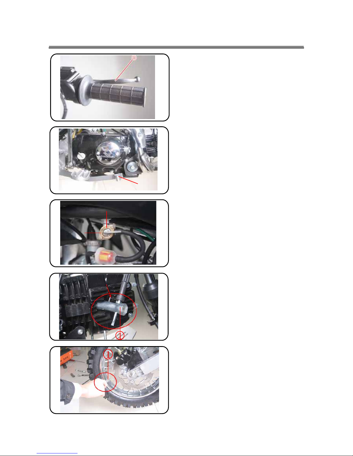
SPOKES INSPECTION AND TIGHTENING
1. Inspect:
Spokes
Bend/damagem Replace.
Loose spoke m Retighten.
2. Tighten:
Spokes
NOTE:
Be sure to retighten these spokes before and
after break-in. After a practice or a race check
spokes for looseness.
T
R
.
.
3 Nm (0.3 m · kg)
WHEEL INSPECTION
1. Inspect:
Wheel runout
Elevate the wheel and turn it.
Abnormal runout m Replace.
①
2
Page 46

3 - 24
STEERING HEAD INSPECTION AND ADJUSTMENT
2. Inspect:
Bearing free play
Exist play m Replace.
STEERING HEAD INSPECTION AND
ADJUSTMENT
1. Elevate the front wheel by placing a suitable stand under the engine.
2. Check:
Steering stem
Grasp the bottom of the forks and gently rock the fork assembly back and
forth.
Free play m Adjust steering head.
3. Check:
Steering smooth action
Turn the handlebar lock to lock.
Unsmooth action m Adjust steering ring
nut.
4. Adjust:
Steering ring nut
Steering ring nut adjustment steps:
Remove the number plate.
Remove the handlebar and handlebar
upper bracket.
Loosen the steering ring nut using the
steering nut wrench .
①
ĸ
Page 47

3 - 25
STEERING HEAD INSPECTION AND ADJUSTMENT
Tighten the steering ring nut using
steering nut wrench .
NOTE:
Apply the lithium soap base grease on the
thread of the steering stem.
Set the torque wrench to the steering nut
wrench so that they form a right angle.
T
R
.
.
Steering ring nut (initial tightening):
30 Nm ( 3 m • kg )
Loosen the steering ring nut one turn.
Retighten the steering ring nut using the
steering nut wrench.
Avoid over-tightening.
Check the steering stem by turning it lock
to lock. If there is any binding, remove the
steering stem assembly and inspect the
steering bearings.
Install the upper bracket ⑤ , washer, steer-
ing stem nut ⑥ , handlebar ⑦ , handlebar
upper holder ⑧
.
CAUTION:
First tighten the bolts on the front side of
the handlebar holder, and then tighten
the bolts on the rear side.
T
R
.
.
Steering stem nut:
70 Nm ( 7 m • kg )
Handlebar upper holder:
25 Nm ( 2.5 m • kg )
③
ĺ
WARNING
Page 48

3 - 26
ELECTRICAL/SPARK PLUG INSPECTION
ELECTRICAL
SPARK PLUG INSPECTION
1. Remove:
Spark plug
2. Inspect:
Electrode ①
Wear/damage m Replace.
Insulator color ②
Normal condition is a medium to light
tan color.
Distinctly different color m Check the
engine condition.
NOTE:
When the engine runs for many hours at low
speeds, the spark plug insulator will become
sooty, even if the engine and carburetor are in
good operating condition.
3. Measure:
Plug gap D
Use a wire gauge or thickness gauge.
Out of specification m Regap.
4. Clean the plug with a spark plug cleaner
if necessary.
Spark plug gap:
0.6 ~ 0.7 mm
5. Tighten:
Spark plug
NOTE:
Before installing a spark plug, clean the gasket surface and plug surface.
Finger-tighten D the spark plug before
torquing to specification E .
T
R
.
.
15 Nm (1.5 m • kg)
Page 49

3 - 27
IGNITION TIMING CHECK
IGNITION TIMING CHECK
1. Remove:
Timing mark accessing screw
2. Check:
Ignition timing
Checking steps:
Start the engine and let it warm up. Let the
engine run at the specified speed.
Engine speed:
1,400 ~ 1,600 r/min
Visually check the stationary pointer D is
within the firing range E on the rotor.
Incorrect firing range m Check rotor and
pickup assembly.
3. Install:
Timing mark accessing screw
Page 50

4 - 1
! ! ! !
Order Job / Part name Q’ty Remarks
1 LEFT TANK COVER
2 RIGHT TANK COVER
3 SEAT
4 LEFT FENDER PLATE
5 RIGHT FENDER PLATE
6 TAIL FENDER
7 FUEL TANK
8 FUEL CAP
9 PET-COCK
Remove the parts in the order listed.
For installation, reverse the removal procedure.
1
1
1
1
1
1
1
1
1
ENGINE
SEAT, FUEL TANK AND SIDE COVERS
2
5
3
6
1
4
7
8
9
SEAT, FUEL TANK AND SIDE COVERS
Page 51

4 - 2
REMOVAL POINTS
Fuel Tank , Side covers and Seat
Remove:
! ! !
SEAT, FUEL TANK AND SIDE COVERS
Bolt for Tank Cover
Right Tank Cover
Seat Bolt
Bolt for Fuel Tank
Fuel Tank
Screw for Tank Cover and Seat
Left Tank Cover
Screw for Fender plate
Left Fender plate
Right Fender plate
Screw for Fender plate
Seat
Page 52

4 - 3
Order Job / Part name Q’ty Remarks
1 BOLT
2 HOOP
3 RUBBER MAT
4 NUT M6×14
5 EXHAUST MUFFLER
6 EXHAUST PIPE SEAL
Remove the parts in the order listed.
For installation, reverse the removal procedure.
1
1
1
2
1
1
5
3
2
4
6
1
NEW
EXHAUST PIPE AND SILENCER
EXHAUST PIPE AND SILENCER
Page 53

4 - 4
EXHAUST PIPE AND SILENCER
INSPECTION
Silencer and exhaust pipe
1. Inspect:
Gasket ①
Damage
Replace.
ASSEMBLY AND INSTALLATION
Silencer and exhaust pipe
1. Install:
Gasket ①
Exhaust muffler
Nut (exhaust pipe)
NOTE:
First, temporarily tighten the Nut ķ (exhaust
pipe), then tighten
the bolt ĸ
T
R
.
.
15 Nm (1.5 m • kg)
2. Install:
Washer
Bolt (silencer)
T
R
.
.
25 Nm (2.5 m • kg)
m
Page 54

4 - 5
Order Job / Part name Q’ty Remarks
1 SCREW FOR AIR-FITER CLAMP
2 AIR-FITER
3 CRBURETOR
4 GASKET,HEAT INSULATING,
CRBURETOR
5 O-RING
6 INLET PIPE
7 O-RING
8 GASKET
Remove the parts in the order listed.
For installation, reverse the removal procedure.
CRBURETOR & AIR-FITER
CRBURETOR & AIR-FITER
1
1
1
2
1
1
1
1
NEW
NEW
NEW
Page 55

4 - 6
CARBURETOR DISASSEMBLY
! ! ! !
Order Job / Part name Q’ty Remarks
1 UPPER COVER
2 GASKET,UPPER COVER
3 RETURN SPRING,AIR THROTTLE
4 V-CLIP
5 E-CIRCLIP
6 NEEDLE,JET
7 AIR THROTTLE
8 O-RING
9 ADJUSTING SCREW,AIR THROTTLE
Remove the parts in the order listed.
For installation, reverse the removal procedure.
10 SPRING,ADJUSTING SCREW
11 O-RING
12 WASHER
13 ADJUSTING SCREW SPRING
14 IDLE FOAM JET
15 MAIN JET,OIL
16 MAIN JET,FOAM
17 MAIN MEASURING HOLE
18 IDLE JET
1
1
1
1
1
1
1
1
1
1
1
1
1
1
1
1
1
1
NEW
NEW
CARBURETOR DISASSEMBLY
Page 56

4 - 7
CARBURETOR DISASSEMBLY
Order Job / Part name Q’ty Remarks
Remove the parts in the order listed.
For installation, reverse the removal procedure.
19 FLOAT COMP
20 NEEDLE VALVE,CARBURETOR
FLOAT
21 HOOK,NEEDLE VALVE
22 FLOAT PIN
23 GASKET,FLOAT CHAMBER
24 DRAIN SCREW
25 O-RING
27 SCREW UNIT,FLOAT CHAMPER
28 PIPE CLIP
29 HOSE
1
1
1
1
1
1
3
1
1
1
NEW
NEW
CARBURETOR DISASSEMBLY
Page 57

4 - 8
CARBURETOR
INSPECTION
Carburetor
1. Inspect:
Carburetor body
Contamination → Clean.
NOTE:
Use a petroleum based solvent for cleaning.
Blow out all passages and jets with compressed air.
Never use a wire.
2. Inspect:
Adjust Screw,Mixture ①
Idle Jet ②
Main Measuring Hole and Main Nozzi ③
Main Jet ④
Drain Screw ⑤
Damage → Replace.
Contamination → Clean.
NOTE:
Use a petroleum based solvent for cleaning.
Blow out all passages and jets with compressed air.
Never use a wire.
Needle valve
1. Inspect:
Needle valve ①
Valve seat ②
Grooved wear b → Replace.
Dust c → Clean.
Jet needle
1. Inspect:
Jet needle ①
Bends/wear → Replace.
Clip groove
Free play exists/wear → Replace.
Clip position
Standard clip position:
No.4 Groove
Page 58

4 - 9
! ! ! !
Order Job / Part name Q’ty Remarks
1 COVER,L.RR.CRANKCASE
2 INITIATIVE CHAIN DRIVER RIVET
PLANK
3 DRIVING GEAR
4 SHIFT PEDAL
5 GUAGE OIL LEVER
6 KICK STARTER
7 SPARK PLUG CAP
8 ENGINE SKID PLATE
Remove the parts in the order listed.
For installation, reverse the removal procedure.
1
1
1
1
1
1
1
1
1
1
1
1
2
SPROCKET REPLACEMENT
1
12
2
3
4
6
7
13
13
10
11
9
9 SIDE STAND
10 RIGHT FOOT PAGS
11 LEFT FOOT PEGS
12 BRACKET FOR PEDAL
13 AXLE
SPROCKET REPLACEMENT
8
5
Page 59

4 - 10
CYLINDER HEAD
CYLINDER HEAD
6
3
2
8
9
7
1
4
5
10
11
Order Job / Part name Q’ty Remarks
1 Spark plug
2 Bolt M6 x 110
3 Cylinder cover L / Gasket
4 Timing driven sprocket
5 Valve cover / O-ring
6 Valve cover / O-ring
7 Cylinder cover
8 Gasket,cylinder cover
9 Cylinder head
Remove the parts in the order listed.
For installation, reverse the removal procedure.
10 Gasket,cylinder head
11 Rectangle ring
1
1
1
1
1
1
1
1
1
1
1
NEW
NEW
NEW
NEW
NEW
NEW
Page 60

4 - 11
CYLINDER HEAD
REMOVING THE CYLINDER HEAD
2. Align:
“I” mark
a
on the generator rotor (with the
stationary pointer
b
on the crankcase cov-
er)
a. Turn the primary pulley counterclockwise.
b. When the piston is at TDC on the compres-
sion stroke, align the “I” mark
c
on the cam-
shaft sprocket with the mark
d
on the cylin-
der head.
3. Loosen:
Bolt
1
1. Remove:
Long Bolt A
4. Remove:
Bolt
2
Nut B
Page 61

4 - 12
CYLINDER HEAD
Bolt
1
Washer
2
Spring Chain Tensioner Push Road ③
NOTE:
To prevent the timing chain from falling into the
crankcase, fasten it with a wire
a
.
While holding the generator rotor bolt with a
wrench, remove the bolt.
Chain Tensioner Push Road Assembly④
5 Remove Chain Tensioner
Page 62

4 - 13
CYLINDER HEAD
NOTE:
NOTE:
NOTE:
6. Remove:
cylinder head
Loosen the
nuts ķĸĹĺĻ
in the proper sequence.
Loosen each nut 1/2 of a turn at a time.
After all of the nuts are fully loosened, remove
them.
CHECKING THE CYLINDER HEAD
1. Eliminate:
combustion chamber carbon deposits
(with a rounded scraper)
Do not use a sharp instrument to avoid damaging or scratching:
spark plug threads
valve seats
2. Check:
cylinder head
Damage/scratches
Replace.
3. Measure:
cylinder head warpage
Out of specification
Resurface the cylin-
der head.
Cylinder head warpage
Less than 0.03 mm
a. Place a straightedge
1
and a thickness
gauge
2
across the cylinder head.
b. Measure the warpage.
c. If the limited isexceeded, resurface the cylin-
der head as follows.
d. Place a 400
600 grit wet abrasive paper
on the surface plate and resurface the cylinder head using a figure-eight sanding pattern.
To ensure an even surface, rotate the cylinder
head several times.
Page 63

4 - 14
CYLINDER HEAD
NOTE:
CHECKING THE TIMING CHAIN TENSIONER
1. Check:
timing chain tensioner
Cracks/damage
Replace.
CHECKING THE TAPPET COVERS AND
CAMSHAFT SPROCKET COVER
The following procedure applies to both of the
tappet covers and O-rings.
1. Check:
tappet cover
camshaft sprocket cover
O-ring
Damage/wear
Replace the defective
part(-s).
INSTALLING THE CYLINDER HEAD
1. Install:
dowel pins
1
O-ring (New)
2
gasket (New)
3
2. Install:
cylinder head
Apply engine oil onto the threads of the cylinder head nuts.
Tighten the cylinder head nuts in the proper
tightening sequence as shown and torque
them in two stages.
Cylinder head nut and bolt
M7 (
1 4
) 15Nm
M6 (
5
) 10Nm
M6 (
6
) 10Nm
M6 (
7
) 10Nm
M30(
8
) 20Nm
1
1
Page 64

4 - 15
CYLINDER HEAD
NOTE:
NOTE:
CAUTION:
6 Nm (0.6 m kg)
INSTALLING THE CAMSHAFT SPROCKET
1. Align:
“I” mark on the generator rotor
(with the mark on the generator rotor cover)
a. Turn the crankshaft counterclockwise.
b. When the piston is at TDC on the compres-
sion stroke, align the “I” mark
a
on the gen-
erator rotor with the mark
b
on the genera-
tor rotor cover.
Be sure to keep the timing chain as tight as possible.
2. Install:
timing chain
(onto the camshaft sprocket)
camshaft sprocket
(onto the camshaft)
The notch
a
on the camshaft should face towards the intake side of the engine.
Align the camshaft marks
a
with the edge of
the cylinder head as shown.
Do not turn the crankshaft when installing
the camshaft to avoid damage or improper
valve timing.
3. Install:
Timing chain tensioner bolt and washer (New)
1
Camshaft sprocket bolts
2
12 Nm (1.2 m kg)
Page 65

4 - 16
Order Job / Part name Q’ty Remarks
1 RIGHT COVER,CYLINDER HEAD
2 GASKET
3 SHAFT,VALVE RROCKER ARM
4 ADJUSTING NUT
5 ADJUSTING SCREW
6 VALVE RROCKER ARM
7 CAM SHAFT
8 VALVE COTTER
9 PETAINER,VALVE SPRING
Remove the parts in the order listed.
For installation, reverse the removal procedure.
1
1
2
2
2
2
1
4
2
2
2
2
1
1
10 VALVE INNER SPRING
11 VALVE OUTER SPRING
12 VALVE STEM SEAL
13 INTAKE VALVE
14 EXHAUST VALVE
CAMSHAFT /VALVES AND VALVE SPRINGS
CAMSHAFT /VALVES AND VALVE SPRINGS
4
3
6
8
9
7
1
2
5
10
11
12
13
14
NEW
NEW
Page 66

4 - 17
CAMSHAFT /VALVES AND VALVE SPRINGS
REMOVING THE ROCKER ARMS AND CAMSHAFT
1. Loosen:
locknuts
1
adjusting screws
2
2. Remove:
3. Remove:
camshaft
1
intake rocker arm shaft ①
exhaust rocker arm shaft ②
intake rocker arm
exhaust rocker arm
CHECKING THE CAMSHAFTS
1. Check:
camshaft bushings
Damage/wear
Replace.
camshaft lobes
Blue discoloration/pitting/ scratches
Replace the camshaft.
3
4
4
3
Page 67

4 - 18
CAMSHAFT /VALVES AND VALVE SPRINGS
A
2 Measure:
camshaft lobe dimensions
A
Out of specification Replace the camshaft.
Camshaft lobe dimension limit
Intake
26.30 mm
Exhaust
26.00 mm
3. Check:
camshaft oil passage
Obstruction
Blow out with compressed air.
CHECKING THE ROCKER ARMS AND
ROCKER ARM SHAFTS
The following procedure applies to all of the
rocker arms and rocker arm shafts.
1. Check:
rocker arm
Damage/wear
Replace.
2. Check:
rocker arm shaft
Blue discoloration / excessive wear/pitting/scratches
Replace or check the lu-
brication system.
3. Check:
camshaft lobe
Excessive wear
Replace the camshaft.
4. Measure:
rocker arm inside diameter
Out of specification
Replace.
Rocker arm inside diameter
10.000
10.015 mm
Limit 10.1 mm
5. Measure:
rocker arm shaft outside diameter
Out of specification
Replace.
Rocker arm shaft outside
diameter
9.98 9.995 mm
Limit 9.910
mm
Page 68

4 - 19
CAMSHAFT /VALVES AND VALVE SPRINGS
NOTE:
NOTE:
NOTE:
6. Calculate:
rocker-arm-to-rocker-arm-shaft clearance
Calculate the clearance by subtracting the rocker arm shaft outside diameter from the rocker
arm inside diameter.
Out of specification
Replace the defective
part(-s).
Rocker-arm-to-rocker-arm-shaft
clearance
0.005
0.035 mm
INSTALLING THE CAMSHAFT AND ROCKER ARMS
1. Lubricate:
rocker arm shaft
Recommended lubricant
Molybdenum disulfide oil
2. Install:
exhaust rocker arm
exhaust rocker arm shaft
Make sure that the exhaust rocker arm shaft is
completely pushed into the cylinder head.
3. Install:
intake rocker arm
intake rocker arm shaft
1
Insert the camshaft into the hole in the cylinder
head and the intake rockerarm shaft as shown .
4. Lubricate:
Camshaft
Recommended lubricant
Camshaft
Molybdenum disulfide oil
Camshaft bearing
Engine oil
3
2
4
Page 69

4 - 20
CAMSHAFT /VALVES AND VALVE SPRINGS
NOTE:
NOTE:
NOTE:
REMOVING THE VALVES
The following procedure applies to all of the
valves and related components.
Before removing the internal parts of the cylinder head (e.g., valves, valve springs, valve
seats), make sure that the valves properly seal.
1. Check:
valve sealing
Leakage at the valve seat
Check the valve
face, valve seat, and valve seat width.
Refer to “CHECKING THE VALVE SEATS”.
a. Pour a clean solvent
a
into the intake and
exhaust ports.
b. Check that the valves properly seal.
There should be no leakage at the valve seat
1
.
2. Remove:
valve cotters
1
Remove the valve cotters by compressing the
valve springs with the valve spring compressor
2
and attachment 3.
3. Remove:
upper spring seat
1
valve springs
2
oil seal
3
4
valve
Identify the position of each part very carefully
so that it can be reinstalled in its original place.
Page 70

4 - 21
CAMSHAFT /VALVES AND VALVE SPRINGS
NOTE:
NOTE:
CHECKING THE VALVES AND VALVE GUIDES
The following procedure applies to all of the
valves and valve guides.
1. Measure:
valve-stem-to-valve-guide clearance
Valve-stem-to-valve-guide clearance =
Valve guide inside diameter
a
–
Valve stem diameter
b
Out of specification Replace the valve
guide.
Valve-stem-to-valve-guide clearance
Intake
0.015
0.042 mm
Limit: 0.08 mm
Exhaust
0.030
0.057 mm
Limit: 0.10 mm
2. Replace:
valve guide
To ease valve guide removal and installation,
and to maintain the correct fit, heat the cylinder
head to 100
C in an oven.
a. Remove the valve guide with a valve guide
remover
1
.
b. Install the new valve guide with a valve guide
installer
2
and valve guide remover 1.
c. After installing the valve guide, bore the
valve guide with a valve guide reamer
3
to
obtain the proper valve-stem-to-valve-guide
clearance.
After replacing the valve guide, reface the valve
seat.
Page 71

4 - 22
CAMSHAFT /VALVES AND VALVE SPRINGS
NOTE:
3. Eliminate:
carbon deposits
(from the valve face and valve seat)
4. Check:
valve face
Pitting/wear
Grind the valve face.
valve stem end
Mushroom shape or diameter larger than the
body of the valve stem
Replace the valve.
5. Measure:
valve margin thickness
a
Out of specification Replace the valve.
Valve margin thickness
0.65
0.95 mm
6. Measure:
valve stem runout
Out of specification
Replace the valve.
When installing a new valve, always replace
the valve guide.
If the valve is removed or replaced, always replace the oil seal.
Valve stem runout
Limit: 0.03 mm
CHECKING THE VALVE SEATS
The following procedure applies to all of the
valves and valve seats.
1. Eliminate:
carbon deposits
(from the valve face and valve seat)
2. Check:
valve seat
Pitting/wear
Replace the cylinder head.
3. Measure:
valve seat width
a
Out of specification Replace the cylinder
head.
Valve seat width
Intake: 0.8
1.2mm
Limit: 1.6 mm
Exhaust: 0.8
1.2mm
Limit: 1.6 mm
Page 72

4 - 23
CAMSHAFT /VALVES AND VALVE SPRINGS
NOTE:
CAUTION:
NOTE:
a. Apply Mechanic’s blueing dye (Dykem)
1
onto the valve face.
b. Install the valve into the cylinder head.
c. Press the valve through the valve guide and
onto the valve seat to make a clear pattern.
d. Measure the valve seat width. Where the
valve seat and valve face contacted one
another, the blueing will have been removed.
4. Lap:
valve face
valve seat
After replacing the cylinder head or replacing
the valve and valve guide, the valve seat and
valve face should be lapped.
a. Apply a coarse lapping compound
a
to the
valve face.
Do not let the lapping compound enter the
gap between the valve stem and the valve
guide.
b. Apply molybdenum disulfide oil onto the
valve stem.
c. Install the valve into the cylinder head.
d. Turn the valve until the valve face and valve
seat are evenly polished, then clean off all of
the lapping compound.
For the best lapping results, lightly tap the valve
seat while rotating the valve back and forth between your hand.
Page 73

4 - 24
CAMSHAFT /VALVES AND VALVE SPRINGS
e. Apply a fine lapping compound to the valve
face and repeat the above steps.
f. After every lapping procedure, be sure to
clean off all of the lapping compound from
the valve face and valve seat.
g. Apply Mechanic’s blueing dye (Dykem)
b
onto the valve face.
h. Install the valve into the cylinder head.
i. Press the valve through the valve guide and
onto the valve seat to make a clear impres-
sion.
j. Measure the valve seat width
c
again. If the
valve seat width is out of specification,reface
and lap the valve seat.
CHECKING THE VALVE SPRINGS
The following procedure applies to all of the
valve springs.
1. Measure:
valve spring free length
a
Out of specification Replace the valve
spring.
Valve spring free length (intake
and exhaust)
Inner spring
33.78 mm Limit: 32.5 mm
Outer spring
35.55 mm Limit: 34.0 mm
2. Measure:
compressed spring force
a
Out of specification Replace the valve
spring.
b
Installed length
Compressed spring force
Intake and exhaust inner
spring
52
64 Nm at 22.45 mm
Intake and exhaust outer
spring
105
129
Nm
at
25.45 mm
3. Measure:
valve spring tilt
a
Out of specification Replace the valve
spring.
Spring tilt limit
Intake and exhaust inner spring
1.3
/0.8 mm
Intake and exhaust outer spring
1.35
/0.8 mm
Page 74

4 - 25
CAMSHAFT /VALVES AND VALVE SPRINGS
NOTE:
NOTE:
CAUTION:
INSTALLING THE VALVES
The following procedure applies to all of the
valves and related components.
1. Deburr:
valve stem end
(with an oil stone)
2. Lubricate:
valve stem
oil seal
(with the recommended lubricant)
Recommended lubricant
Molybdenum disulfide oil
3. Install:
valve
1
oil seal
2
valve springs
3
upper spring seat
4
(into the cylinder head)
Install the valve springs with the larger pitch a
facing up.
4. Install:
valve cotters
1
Install the valve cotters by compressing the
valve springs with the valve spring compressor
2
and attachment3.
5. To secure the valve cotters onto the valve
stem, lightly tap the valve tip with a soft-face
hammer.
Hitting the valve tip with excessive force
could damage the valve.
Page 75

4 - 26
CYLINDER AND PISTON
Order Job / Part name Q’ty Remarks
1 PIN SHAFT,GUIDEROLLER
2 CAM CHAIN GUIDE
ROLLER
3 CYLINDER BLOCK
4 GASKET,CYLINDER BLOCK
5 DOWEL PIN
6 RECTANGLE RING
7 CIRCLIP,PISTON PIN
8 PISTON PIN
9 PISTON
Remove the parts in the order listed.
For installation, reverse the removal procedure.
5
3
2
6
1
4
CYLINDER AND PISTON
7
NEW
NEW
7
8
1
1
1
1
1
1
1
2
1
1
1
NEW
NEW
9
10 PISTON RING
Page 76

4 - 27
CYLINDER AND PISTON
NOTE:
NOTE:
NOTE:
REMOVING THE PISTON AND PISTON
RINGS
1. Remove:
piston pin circlip
1
piston pin
2
piston
3
Before removing the piston pin circlip, cover the
crankcase opening with a clean towel or rag to
prevent the circlip from falling into the crankcase cavity.
2. Remove:
top ring
2nd ring
oil ring
When removing the piston ring, open the end
gap of the ring by fingers, and push up the other
side of the ring.
CHECKING THE CYLINDER AND PISTON
1. Check:
piston wall
cylinder wall
Vertical scratches
Rebore or replace the
cylinder, and replace the piston and piston
rings as a set.
2. Measure:
piston-to-cylinder clearance
a. Measure cylinder bore “C” with the cylinder
bore gauge.
Measure cylinder bore “C” by taking side-toside and front-to-back measurements of the
cylinder. Then, find theaverage of themeasurements.
Cylinder bore “C”
54.00 54.015 mm
Taper limit ”T” 0.05 mm
Out of round “R” 0.005 mm
”C” = Maximum D
”T” = (Maximum D1 or D2)–
(Maximum D
5
or D6)
”R” = (Maximum D1, D3 or D5)
– (Minimum D
2
, D4 or D6)
Page 77

4 - 28
CYLINDER AND PISTON
NOTE:
b. If out of specification, rebore or replace the
cylinder, and replace the piston and piston
rings as a set.
c. Measure piston skirt diameter “P” with the
micrometer.
1
7.0 mm from the bottom edge of the piston.
Piston size “P”
Standard 53.965 53.975 mm
d. If out of specification, replace the piston and
piston rings as a set.
e. Calculate the piston-to-cylinder clearance
with the following formula.
Piston-to-cylinder clearance =
Cylinder bore “C” –
Piston skirt diameter “P”
Piston-to-cylinder clearance
0.025
0.05 mm
f. If out of specification, rebore or replace the
cylinder, and replace the piston and piston
rings as a set.
CHECKING THE PISTON RINGS
1. Measure:
piston ring side clearance
Out of specification
Replace the piston
and piston rings as a set.
Before measuring the piston ring side clearance, eliminate any carbon deposits from the
piston ring grooves and piston rings.
Piston ring side clearance
Top ring
0.04
0.08 mm
<Limit>: 0.12mm
2nd ring
0.04
0.08 mm
<Limit>: 0.12mm
Page 78

4 - 29
CYLINDER AND PISTON
NOTE:
NOTE:
2. Install:
piston ring
(into the cylinder)
Level the piston ring in the cylinder with the piston crown as shown.
a
5.0 mm
3. Measure:
piston ring end gap
Out of specification
Replace the piston
ring.
The oil ring expander spacer’s end gap cannot
be measured. If the oil ring rail’s gap is excessive, replace all three piston rings.
Piston ring end gap
Top ring
0.10
0.25 mm
<Limit>: 0.60 mm
2nd ring
0.15
0.30 mm
<Limit>: 0.60 mm
Oil ring
0.2
0.5 mm
CHECKING THE PISTON PIN
1. Check:
piston pin
Blue discoloration / grooves
Replace the
piston pin and then check the lubrication system.
2. Measure:
piston pin outside diameter
a
Out of specification Replace the piston
pin.
Piston pin outside diameter
13.994
14.000 mm
3. Calculate:
piston-pin-to-piston clearance
Out of specification Replace the piston pin
and piston as a set.
Page 79

4 - 30
CYLINDER AND PISTON
NOTE:
New
NOTE:
New
Piston-pin-to-piston clearance =
Piston pin bore size
b
–
Piston pin outside diameter
a
Piston-pin-to-piston clearance
0.002
0.019 mm
INSTALLING THE PISTON AND CYLINDER
1. Install:
top ring
1
2nd ring
2
lower oil ring rail
5
upper oil ring rail
oil ring expander
Be sure to install the piston rings so that the
manufacturer’s marks or numbers face up.
2. Install:
piston
1
piston pin
2
piston pin clip
3
Apply engine oil onto the poston pin.
Make sure that the mark “IN” on the piston
points towards the intake side ofthe cylinder.
Before installing the piston pin clip, cover the
crankcase opening with a clean rag to prevent
the clip from falling into the crankcase.
3. Install:
gasket
1
dowel pins
2
4. Lubricate:
piston
piston rings
cylinder
(with the recommended lubricant)
Recommended lubricant
Engine oil
4
3
Page 80

4 - 31
CYLINDER AND PISTON
NOTE:
5. Offset:
piston ring end gaps
a
Top ring
b
Lower oil ring rail
c
Upper oil ring rail
d
2nd ring
6. Install:
cylinder
1
While compressing the piston rings with one
hand, install the cylinder with the other hand.
Pass the timing chain and timing chain guide
(exhaust side) through the timing chain cavity.
Page 81

4 - 32
! ! ! !
CLUTCH
Order Job / Part name Q’ty Remarks
1 DECORATE COVER,R CRANK
CASE COVER
2 GASKET,DECORATE COVER
3 CLUTCHLEVER PIN
4 CLUTCHLEVER ASSY
5 CLUTCH CAM SHAFT SPRING
6 O-RING
7 CLUTCH SHIFTING PLATE
8 CLUTCH PRESSURE PLATE
9 OIL SEAL
Remove the parts in the order listed.
For installation, reverse the removal procedure.
CLUTCH
1
1
1
1
1
1
1
1
1
1
1
1
1
1
1
1
1
1
1
2
ˠ
ˡ
ˢ
ˣ
7
8
10
11
9
12
13
14
15
16
18
19
20
2122
17
23
24
25
26
27
28
10 OIL SEAL
11 R ,CRANK CASE COVER
12 GASKET,R ,CRANK CASE COVER
13 CLUTCH PUSH ROD
14 OIL TUBE
15 OIL THIMBLE SPRING
16 OIL THIMBLE
17 BEARING
18 CLUTCH END COVER
NEW
NEW
NEW
NEW
NEW
NEW
Page 82

4 - 33
! ! ! !
CLUTCH
Order Job / Part name Q’ty Remarks
Remove the parts in the order listed.
For installation, reverse the removal procedure.
CLUTCH
1
1
1
1
1
1
1
1
1
1
19 GASKET,END COVER
20 NUT
21 WASHER
22 THURST WASHER
23 CLUTCH ASSY
24 DRIVER GEAR
25 SLEEVE
26 BUSH
27 CIRCLIP
28 DRIVEN GEAR CAM
1
2
ˠ
ˡ
ˢ
ˣ
7
8
10
11
9
12
13
14
15
16
18
19
20
2122
17
23
24
25
26
27
28
NEW
NEW
NEW
NEW
NEW
NEW
Page 83

1 CIRCLIP
2 PLATE
3 CLUTCH DRIVE FRICTION PLATE
4 CLUTCH CENTER SLEEVE
5 DRIVE PLATE
6 CLUTCH CUSHION SPRING
7 CLUTCH SPRING
8 CLUTCH OUTER CASE
4 - 34
! ! ! !
CLUTCH
Order Job / Part name Q’ty Remarks
Remove the parts in the order listed.
For installation, reverse the removal procedure.
CLUTCH
1
3
3
1
1
1
1
1
1
1
2
3
4
3
5
6
8
7
2
2
3
Page 84

4 - 35
CLUTCH
NOTE:
NOTE:
REMOVING THE CLUTCH
2. Straighten the lock washer tab ③
3. Remove:
clutch boss nut ①
While holding the clutch boss with the universal clutch holder , loosen the clutch boss nut.
CHECKING THE FRICTION PLATES
The following procedure applies to all of the friction plates.
1. Check:
friction plate
Damage/wear
Replace the friction plates
as a set.
2. Measure:
friction plate thickness
Out of specification
Replace the friction
plates as a set.
Measure the friction plate at four places.
Friction plate thickness
2.85
2.95 mm
<Limit>: 2.7 mm
CHECKING THE CLUTCH PLATES
The following procedure applies to all of the
clutch plates.
1. Check:
clutch plate
Damage
Replace the clutch plates as a
set.
1. Remove:
Screw
-
4. Remove:
snap spring ①
washer ②
Page 85

4 - 36
CLUTCH
NOTE:
NOTE:
2. Measure:
clutch plate warpage
(with a surface plate and thickness gauge
1
)
Out of specification
Replace the clutch
plates as a set.
Clutch plate warpage limit
Less than 0.1
mm
CHECKING THE CLUTCH SPRINGS
The following procedure applies to all of the
clutch springs.
1. Check:
clutch spring
Damage
Replace the clutch springs as a
set.
2. Measure:
clutch spring free length
Out of specification
Replace the clutch
springs as a set.
Clutch spring free length
20.5 mm
<Limit>: 19.5 mm
CHECKING THE CLUTCH OUTER CASE
1. Check:
clutch outer case dogs
Damage/pitting/ wear
Deburr the clutch
outer case dogs or replace it.
Pitting on the clutch housing dogs will cause erratic clutch operation.
CHECKING THE CLUTCH CENTER SLEEVE
1. Check:
clutch center sleeve splines
Damage/pitting/ wear
Replace the clutch
center sleeve.
Pitting on the clutch sleeve splines will cause erratic clutch operation.
Page 86

4 - 37
CLUTCH
NOTE:
2. Lubricate:
friction plates ③
upper plates ④
First, install a friction plate and then alternate
between a upper plate and a friction plate.
(with the recommended lubricant)
Recommended lubricant
Engine oil
INSTALLING THE CLUTCH ASSY
1. Install:
put the clutch spring ① into the clutch outer case.
put the drive plate ② into the clutch outer case.
3. Install:
friction plates ③
upper plates ④
4. Install:
pressure plate and install clutch circlip ⑤
Page 87

4 - 38
CLUTCH
NOTE:
60 Nm (6.0 m kg)
NOTE:
CHECKING THE CLUTCH PUSH RODS
1. Check:
oil tube
1
oil thimble spring
2
oil thimble
3
Cracks/damage/ wear Replace the defective part(-s).
2. Measure:
oil thimble spring ② free length
Out of specification Replace the oil thimble spring.
Oil thimble spring free length
17.5 mm
INSTALLING THE CLUTCH
1. Install:
clutch assy
1
thrust washer④,make sure the “OUT SIDE”
mark on the washer is upturned.
Make sure that the teeth on the lock washer are
correctly aligned with the grooves on the clutch
boss.
2. Tighten:
clutch boss nut
5
While holding the clutch boss with the universal
clutch holder , tighten the clutch boss nut.
3. Bend the lock washer tab ③ along a flat side
of the nut.
Page 88

4 - 39
CLUTCH
NOTE:
6 Nm (0.6 m • kg)
4. Install:
oil tube
1
oil thimble spring
2
oil thimble
3
screw ķĺ
5. Check
clutch assy
Make sure that the teeth on the lock washer are
correctly aligned with the grooves on the clutch
boss.
Page 89

4 - 40
! ! ! !
Order Job / Part name Q’ty Remarks
Remove the parts in the order listed.
For installation, reverse the removal procedure.
OIL PUMP
1
1
1
1 OIL PUMP
2 OIL FILTER SCREEN
3 GEAR
OIL PUMP
1
2
NEW
3
Page 90

4 - 41
OIL PUMP
NOTE:
REMOVING THE OIL PUMP
2. Remove:
gasket of oil pump ①
Remove the gasket of oil pump and check the
state.Replace if worn or if reuse if questionable.
1. Remove:
Screw ① - ③.
gear of oil pump ②
3. Check:
Remove the oil pump and inspect oil way for
smoothness.clean oil way as necessary.
Check whether the gear is worn.
Page 91

4 - 42
Order Job / Part name Q’ty Remarks
1 FRONT COVER, LEFT CRANKCASE
2 GASKET, LEFT CRANKCASE
3 STATOR , MAGNETO
4 NUT
5 COTOR , MAGNETO
6 CIRCLIP 10
7 DRIVEN SPROCKET, STARTING
MOTOR
8 DRIVE SPROCKET, STARTING
MOTOR
9 STARTING MOTOR DRIVE CHAIN
Remove the parts in the order listed.
For installation, reverse the removal procedure.
10 OIL SEAL 19×30×5
11 OIL SEAL
12 CHAIN PROTECT PLATE
13 CHAIN GUIDE PLATE
14 WOODRUFF KEY
1
1
1
1
1
1
1
1
1
1
1
1
1
1
MAGNETO AND STARTER GEAR
1
3
5
2
4
10
9
7
8
12
6
11
MAGNETO AND STARTER GEAR
13
NEW
NEW
NEW
NEW
14
Page 92

4 - 43
MAGNETO AND STARTER GEAR
NOTE:
REMOVING THE GENERATOR ROTOR
1. Remove:
bolt
1
(magneto)
Loosen the bolt (generator rotor) 1 while
holding the rotor with a sheave holder
2
.
Do not allow the sheave holder to touch the
projection on the rotor.
2. Remove:
generator rotor
1
woodruff key ②
CHECKING THE STARTER CLUTCH
1. Check:
1
starter clutch drive gear
2
starter clutch gear
Burrs/chips/ roughness / wear
Replace
the defective part(-s).
3. Remove:
circlip
1
bolt ②
Page 93

4 - 44
MAGNETO AND STARTER GEAR
30 Nm (3.0 m kg)
b. When turning the starter clutch gear clock-
wise
a
, the starter clutch and the starter
clutch gear should engage.
If the starter clutch gear and starter clutch do
not engage, the starter clutch is faulty and
must be replaced.
c. When turning the starter clutch gear counter-
clockwise
b
, it should turn freely.
If the starter clutch gear does not turn freely,
the starter clutch is faulty and must be replaced.
3. Inspect:
dowel pins
1
compression springs
2
spring caps
3
Wear/Damage Replace.
4. Inspect:
starter wheel gear
(contacting surface)
Pitting/Wear/Damage
Replace.
INSTALLING THE STARTER CLUTCH
1. Install:
starter clutch assembly
1
2. Unloosen the starter clutch assembly by using the center punch.
3. Install:
compression springs
1
spring caps
2
dowel pins
3
2. Check:
starter clutch operation
a. Hold the starter clutch.
Page 94

4 - 45
MAGNETO AND STARTER GEAR
NOTE:
50 Nm (5.0 m kg)
NOTE:
INSTALLING THE GENERATOR ROTOR
1. Install:
1
starter wheel gear
2
woodruff key
3. Install:
generator rotor
1
Clean the tapered portion of the crankshaft
and the rotor hub.
When installing the rotor, make sure the woodruff key is properly seated in the key way of the
crankshaft and turning the starter wheel gear
clockwise.
4. Tighten:
generator rotor
2
Tighten the bolt while holding the generator rotor with the sheave holder .
2. Install:
starting motor drive chain ①
drive gear ②
cirlip ③
bolt ④
chain protect plate ⑤
Page 95

4 - 46
Order Job / Part name Q’ty Remarks
1 CLIP, VOLTAGE WIRE
2 LOWER PAN, OIL INSULATING
3 O-RING
4 OIL SEAL
5 BOLT M14×1.5
6 WASHER
7 SPRING, CHAIN TENSIONER PUSH
ROD
8 CHAIN TENSIONER PUSH ROD
9 TIGHTENING ROD HEAD
Remove the parts in the order listed.
For installation, reverse the removal procedure.
10 TIMING CHAIN
11 TIGHTENING ARM SHAFT
12 TIGHTENING ARM
13 TIGHTENING IDLER WHEEL SET
14 OIL PUMP DRIVE SPROCKET
1
1
1
1
1
1
1
1
1
1
1
1
1
1
CAM CHAIN-TENSIOR
CAM CHAIN-TENSIOR
1
4
3
2
5
6
7
8
9
11
12
13
14
10
NEW
NEW
Page 96

4 - 47
CAM CHAIN-TENSIOR
20 Nm (2.0 m • kg)
1. Remove:
bolt of cam chain tensior ①
roller of cam chain tensior
2
cam chain
3
2. Check:
aluminium washer ①
Pitting/Wear/Damage Replace.
INSTALLING THE CAM CHAIN TENSIOR
1. Install:
bolt of cam chain tensior
1
spring of chain tensior push rod
Pitting/Wear/Damage Replace.
CAM CHAIN TENSIOR
Page 97

4 - 48
! ! ! !
Order Job / Part name Q’ty Remarks
1 BOLT, LOCATING PLATE
LOCATING PLATE GROUP
2 RETURN SPRING, LOCATING
PLATE
3 RETURN SPRING, GEARSHIFT
LEVER
4 BUSH
5 GEARSHIFT LEVER BODY ASSY
6 TENSION SPRING, GEARSHIFT
LEVER
7 STOP PLATE
8 BOLT M8×11
9 CIRCLIP 16
Remove the parts in the order listed.
For installation, reverse the removal procedure.
10 SPRING
11 SPRING SHAFE SPRING BASE
1
1
1
1
1
1
1
1
1
1
1
CRANKSHAFT AND GEARSHIFT ARM
CRANKSHAFT AND GEARSHIFT ARM
13
13
14
14
15
16
17
17
17
18
19
20
21
22
23
24
25
6
11
10
12
1
2
5
8
7
4
3
10
11
9
Page 98

4 - 49
! ! ! !
Order Job / Part name Q’ty Remarks
13 CYLINDER STUD BOLT B M7 X 204
14 CYLINDER STUD BOLT A M7 X 212
15 OIL DRAIN PLUG M12×1.5
16 WASHER 12.5×1.5×20
17 BOLT M6×65
18 BOLT M6×60
19 BOLT M6×45
20 BOLT M6×60
21 BREATHER TUBE C100-2#
Remove the parts in the order listed.
For installation, reverse the removal procedure.
22 LEFT CRANKCASE
23 GASKET, CRANKCASE
24 RIGHT CRANKCASE
25 TIE-IN, BREATHER TUBE
1
2
2
1
1
3
1
1
1
1
1
1
1
1
CRANKSHAFT AND GEARSHIFT ARM
CRANKSHAFT AND GEARSHIFT ARM
13
13
14
14
15
16
17
17
17
18
19
20
21
22
23
24
25
6
11
10
12
1
2
5
8
7
4
3
10
11
9
12 CONTACT, GEAR INDICATION
Page 99

4 - 50
CRANKSHAFT AND GEARSHIFT ARM
DISASSEMBLING THE CRANKCASE
1. Gearshift arm ①:
bolt of locating plate ②
2. Remove:
cirlip ①
Remove:
bolt of locating plate ③
spring ②
spring seat ③
Page 100

4 - 51
CRANKSHAFT
NOTE:
NOTE:
CAUTION:
DISASSEMBLING THE CRANKCASE
1. Remove:
crankcase bolts
Loosen each bolt 1/4 of a turn at a time, in
stages and in a crisscross pattern. After all of
the bolts are fully loosened, remove them.
Loosen the bolts in decreasing numerical order (refer to the numbers in the illustration).
The numbers embossed on the crankcase indicate the crankcase tightening sequence.
2. Remove:
right crankcase
Set the left crankcase half under then put in the
flat head screw driver to the separating slit .
First check that the shift drum segment’s
teeth and the drive axle circlip are properly
positioned, then remove the right crankcase.
Do not damage the crankcase mating surfaces.
1
5
~
 Loading...