

Page 1

A10E/A28E/A28F
Configuration Guide
Page 2

Orion Networks provides customers with comprehensive technical support and services. For any assistance, please
contact our local office or company headquarters.
Website: http://www.orionnetworks.com
Tel: 512.646.4025
Email: info@orionnetworks.com
Address: 4262 Entry Ct STE K, Chantilly, VA 20151 USA
-----------------------------------------------------------------------------------------------------------------------------------------
Notice
Copyright © 2013
Orion Networks
All rights reserved.
No part of this publication may be excerpted, reproduced, translated or utilized in any form or by any means,
electronic or mechanical, including photocopying and microfilm, without permission in Writing from Orion
Networks.
is the trademark of Orion Networks.
All other trademarks and trade names mentioned in this document are the property of their respective holders.
The information in this document is subject to change without notice. Every effort has been made in the
preparation of this document to ensure accuracy of the contents, but all statements, information, and
recommendations in this document do not constitute the warranty of any kind, express or implied.
Page 3

Orion Networks
A10E/A28E/A28F Configuration Guide
Preface
Orion Networks
i
Product name
Hardware version
Software version
A10E
A
NOS_4.14
A28E
A
NOS_4.14
Symbol
Description
Indicates a hazard with a medium or low level of risk which, if
not avoided, could result in minor or moderate injury.
Indicates a potentially hazardous situation that, if not avoided,
could cause equipment damage, data loss, and performance
degradation, or unexpected results.
Provides additional information to emphasize or supplement
important points of the main text.
Preface
Objectives
This guide describes features supported by the A10E/A28E, and related configurations,
including basic principles and configuration procedure of Ethernet, route, reliability, OAM,
security, and QoS, and related configuration examples.
The appendix lists terms, acronyms, and abbreviations involved in this document.
By reading this guide, you can master principles and configurations of the A10E/A28E, and
how to network with the A10E/A28E.
Versions
The following table lists the product versions related to this document.
Conventions
Symbol conventions
The symbols that may be found in this document are defined as follows.
Page 4

Orion Networks
A10E/A28E/A28F Configuration Guide
Preface
Orion Networks
ii
Symbol
Description
Indicates a tip that may help you solve a problem or save time.
Convention
Description
Times New Roman
Normal paragraphs are in Times New Roman.
Arial
Paragraphs in Warning, Caution, Notes, and Tip are in Arial.
Boldface
Names of files, directories, folders, and users are in boldface.
For example, log in as user root.
Italic
Book titles are in italics.
Lucida Console
Terminal display is in Lucida Console.
Convention
Description
Boldface
The keywords of a command line are in boldface.
Italic
Command arguments are in italics.
[]
Items (keywords or arguments) in square brackets [ ] are
optional.
{ x | y | ... }
Alternative items are grouped in braces and separated by
vertical bars. Only one is selected.
[ x | y | ... ]
Optional alternative items are grouped in square brackets and
separated by vertical bars. One or none is selected.
{ x | y | ... } *
Alternative items are grouped in braces and separated by
vertical bars. A minimum of one or a maximum of all can be
selected.
[ x | y | ... ] *
Optional alternative items are grouped in square brackets and
separated by vertical bars. A minimum of none or a maximum
of all can be selected.
General conventions
Command conventions
Page 5

Orion Networks
A10E/A28E/A28F Configuration Guide
Preface
Orion Networks
iii
Convention
Description
Boldface
Buttons, menus, parameters, tabs, windows, and dialog titles
are in boldface. For example, click OK.
>
Multi-level menus are in boldface and separated by the ">"
signs. For example, choose File > Create > Folder.
Format
Description
Key
Press the key. For example, press Enter and press Tab.
Key 1+Key 2
Press the keys concurrently. For example, pressing Ctrl+C
means the two keys should be pressed concurrently.
Key 1, Key 2
Press the keys in turn. For example, pressing Alt, A means the
two keys should be pressed in turn.
Action
Description
Click
Select and release the primary mouse button without moving
the pointer.
Double-click
Press the primary mouse button twice continuously and quickly
without moving the pointer.
Drag
Press and hold the primary mouse button and move the pointer
to a certain position.
GUI conventions
Keyboard operation
Mouse operation
Page 6

Orion Networks
A10E/A28E/A28F Configuration Guide
Contents
Orion Networks
iv
Contents
Preface ....................................................................................................................................... 1
Objectives .......................................................................................................................................... 1
Versions ............................................................................................................................................. 1
Conventions ....................................................................................................................................... 1
Symbol conventions ....................................................................................................................................1
General conventions ...................................................................................................................................2
Command conventions ...............................................................................................................................2
GUI conventions ..........................................................................................................................................3
Keyboard operation ....................................................................................................................................3
Mouse operation.........................................................................................................................................3
Contents .................................................................................................................................... 4
Figures ..................................................................................................................................... 16
Tables ...................................................................................................................................... 18
1 Basic configurations ................................................................................................................. 1
1.1 Accessing the device ..................................................................................................................... 1
1.1.1 Introduction .......................................................................................................................................1
1.1.2 Accessing from the Console interface ................................................................................................2
1.1.3 Accessing from Telnet ........................................................................................................................3
1.1.4 Accessing from SSHv2 ........................................................................................................................4
1.1.5 Checking configurations .....................................................................................................................6
1.2 CLI ................................................................................................................................................ 6
1.2.1 Introduction .......................................................................................................................................6
1.2.2 Command line level ...........................................................................................................................7
1.2.3 Command line mode ..........................................................................................................................7
1.2.4 Command line shortcuts ....................................................................................................................9
1.2.5 Command line help message .......................................................................................................... 10
1.2.6 CLI message ..................................................................................................................................... 12
1.2.7 Command line history message ...................................................................................................... 13
1.2.8 Restoring default value of command line ....................................................................................... 14
1.3 Managing users ........................................................................................................................... 14
1.3.1 Checking configurations .................................................................................................................. 15
1.4 Managing files ............................................................................................................................ 15
1.4.1 Managing BootROM files ................................................................................................................ 15
1.4.2 Managing system files ..................................................................................................................... 17
1.4.3 Managing configuration files .......................................................................................................... 18
1.4.4 Checking configurations .................................................................................................................. 19
Page 7

Orion Networks
A10E/A28E/A28F Configuration Guide
Contents
Orion Networks
v
1.5 Configuring clock management.................................................................................................... 19
1.5.1 Configuring time and time zone...................................................................................................... 19
1.5.2 Configuring DST ............................................................................................................................... 20
1.5.3 Configuring NTP .............................................................................................................................. 20
1.5.4 Configuring SNTP ............................................................................................................................ 21
1.5.5 Checking configurations .................................................................................................................. 22
1.6 Configuring interface management .............................................................................................. 22
1.6.1 Default configurations of interfaces ................................................................................................ 22
1.6.2 Configuring basic attributes for interfaces ...................................................................................... 23
1.6.3 Configuring flow control on interfaces ........................................................................................... 23
1.6.4 Configuring the Combo interface .................................................................................................... 24
1.6.5 Configuring interface rate statistics ................................................................................................ 24
1.6.6 Configuring interface statistics ........................................................................................................ 25
1.6.7 Enabling/Disabling interfaces ......................................................................................................... 25
1.6.8 Checking configurations .................................................................................................................. 25
1.7 Configuring basic information ...................................................................................................... 26
1.8 Task scheduling ........................................................................................................................... 27
1.9 Watchdog ................................................................................................................................... 27
1.10 Load and upgrade...................................................................................................................... 28
1.10.1 Introduction .................................................................................................................................. 28
1.10.2 Configuring TFTP auto-upload method ......................................................................................... 29
1.10.3 Upgrading system software by BootROM ..................................................................................... 29
1.10.4 Upgrading system software by CLI ................................................................................................ 31
1.10.5 Checking configurations ................................................................................................................ 32
1.10.6 Exampe for configuring TFTP auto-loading ................................................................................... 32
2 Ethernet ................................................................................................................................ 34
2.1 MAC address table ...................................................................................................................... 34
2.1.1 Introduction .................................................................................................................................... 34
2.1.2 Preparing for configurations ........................................................................................................... 36
2.1.3 Default configurations of MAC address table ................................................................................. 36
2.1.4 Configuring static MAC address ...................................................................................................... 36
2.1.5 Configuring multicast filtering mode for MAC address table ......................................................... 37
2.1.6 Configuring MAC address learning.................................................................................................. 37
2.1.7 Configuring MAC address limit ....................................................................................................... 38
2.1.8 Configuring the aging time of MAC addresses ................................................................................ 38
2.1.9 Checking configurations .................................................................................................................. 38
2.1.10 Maintenance ................................................................................................................................. 39
2.1.11 Example for configuring the MAC address table........................................................................... 39
2.2 VLAN .......................................................................................................................................... 40
2.2.1 Introduction .................................................................................................................................... 40
2.2.2 Preparing for configurations ........................................................................................................... 42
2.2.3 Default configurations of VLAN ....................................................................................................... 42
2.2.4 Configuring VLAN attributes ........................................................................................................... 43
2.2.5 Configuring interface mode ............................................................................................................ 43
2.2.6 Configuring VLAN on Access interface ............................................................................................ 44
2.2.7 Configuring VLAN on the Trunk interface ....................................................................................... 44
2.2.8 Checking configurations .................................................................................................................. 45
2.3 QinQ ........................................................................................................................................... 46
2.3.1 Introduction .................................................................................................................................... 46
Page 8

Orion Networks
A10E/A28E/A28F Configuration Guide
Contents
Orion Networks
vi
2.3.2 Preparing for configurations ........................................................................................................... 47
2.3.3 Default configurations of QinQ ....................................................................................................... 47
2.3.4 Configuring basic QinQ ................................................................................................................... 47
2.3.5 Configuring selective QinQ ............................................................................................................. 47
2.3.6 Configuring the egress interface toTrunk mode ............................................................................. 48
2.3.7 Checking configurations .................................................................................................................. 48
2.3.8 Maintenance ................................................................................................................................... 48
2.3.9 Example for configuring basic QinQ ................................................................................................ 49
2.3.10 Example for configuring selective QinQ ........................................................................................ 51
2.4 VLAN mapping ............................................................................................................................ 54
2.4.1 Introduction .................................................................................................................................... 54
2.4.2 Preparing for configurations ........................................................................................................... 55
2.4.3 Configuring 1:1 VLAN mapping ....................................................................................................... 55
2.4.4 Configuring N:1 VLAN mapping ...................................................................................................... 55
2.4.5 Checking configurations .................................................................................................................. 56
2.4.6 Example for configuring VLAN mapping ......................................................................................... 56
2.5 Interface protection .................................................................................................................... 58
2.5.1 Introduction .................................................................................................................................... 58
2.5.2 Preparing for configurations ........................................................................................................... 59
2.5.3 Default configurations of interface protection ............................................................................... 59
2.5.4 Configuring interface protection ..................................................................................................... 59
2.5.5 Checking configurations .................................................................................................................. 59
2.5.6 Example for configuring interface protection ................................................................................. 60
2.6 Port mirroring ............................................................................................................................. 63
2.6.1 Introduction .................................................................................................................................... 63
2.6.2 Preparing for configurations ........................................................................................................... 63
2.6.3 Default configurations of port mirroring ........................................................................................ 64
2.6.4 Configuring port mirroring on a local port ...................................................................................... 64
2.6.5 Checking configurations .................................................................................................................. 65
2.6.6 Example for configuring port mirroring .......................................................................................... 65
2.7 Layer 2 protocol transparent transmission ................................................................................... 66
2.7.1 Introduction .................................................................................................................................... 66
2.7.2 Preparing for configurations ........................................................................................................... 67
2.7.3 Default configurations of Layer 2 protocol transparent transmission ............................................ 67
2.7.4 Configuring transparent transmission parameters ......................................................................... 67
2.7.5 Checking configuration ................................................................................................................... 68
2.7.6 Maintenance ................................................................................................................................... 68
2.7.7 Configuring Layer 2 protocol transparent transmission.................................................................. 68
3 IP services ............................................................................................................................. 72
3.1 ARP ............................................................................................................................................ 72
3.1.1 Introduction .................................................................................................................................... 72
3.1.2 Preparing for configurations ........................................................................................................... 73
3.1.3 Default configurations of ARP ......................................................................................................... 73
3.1.4 Configuring static ARP table entries ................................................................................................ 73
3.1.5 Configuring aging time of dynamic ARP entries ............................................................................. 74
3.1.6 Configuring dynamic ARP entry learning mode .............................................................................. 74
3.1.7 Checking configurations .................................................................................................................. 74
3.1.8 Maintenance ................................................................................................................................... 74
3.1.9 Configuring ARP .............................................................................................................................. 75
Page 9

Orion Networks
A10E/A28E/A28F Configuration Guide
Contents
Orion Networks
vii
3.2 Layer 3 interface ......................................................................................................................... 76
3.2.1 Introduction .................................................................................................................................... 76
3.2.2 Preparing for configurations ........................................................................................................... 76
3.2.3 Configuring the Layer 3 interface .................................................................................................... 76
3.2.4 Checking configurations .................................................................................................................. 77
3.2.5 Example for configuring Layer 3 interface to interconnect with host ............................................. 77
3.3 Default gateway .......................................................................................................................... 79
3.3.1 Introduction .................................................................................................................................... 79
3.3.2 Preparing for configurations ........................................................................................................... 79
3.3.3 Configuring the default gateway ..................................................................................................... 79
3.3.4 Configuring static route ................................................................................................................... 80
3.3.5 Checking configurations .................................................................................................................. 80
3.4 DHCP Client ................................................................................................................................ 80
3.4.1 Introduction .................................................................................................................................... 80
3.4.2 Preparing for configurations ........................................................................................................... 83
3.4.3 Default configurations of DHCP client ............................................................................................. 83
3.4.4 Applying the IP address through DHCP ........................................................................................... 83
3.4.5 (Optional) configuring DHCP client ................................................................................................. 84
3.4.6 (Optional) Renewing or releasing the IP address ............................................................................ 84
3.4.7 Checking configurations .................................................................................................................. 85
3.4.8 Configuring DHCP clients application .............................................................................................. 85
3.5 DHCP Relay ................................................................................................................................. 86
3.5.1 Introduction .................................................................................................................................... 86
3.5.2 Preparing for configurations ........................................................................................................... 87
3.5.3 Default configurations of DHCP Relay ............................................................................................. 87
3.5.4 Configuring global DHCP Relay ....................................................................................................... 87
3.5.5 Configuring interface DHCP Relay ................................................................................................... 87
3.5.6 Configuring the destination IP address for forwarding packets ...................................................... 88
3.5.7 (Optional) configuring DHCP Relay to support Option 82 .............................................................. 88
3.5.8 Checking configurations .................................................................................................................. 88
3.6 DHCP Snooping ........................................................................................................................... 89
3.6.1 Introduction .................................................................................................................................... 89
3.6.2 Preparing for configurations ........................................................................................................... 90
3.6.3 Default configurations of DHCP Snooping ...................................................................................... 90
3.6.4 Configuring DHCP Snooping ............................................................................................................ 90
3.6.5 Checking configurations .................................................................................................................. 91
3.6.6 Example for configuring DHCP Snooping ........................................................................................ 91
3.7 DHCP options .............................................................................................................................. 93
3.7.1 Introduction .................................................................................................................................... 93
3.7.2 Preparing for configurations ........................................................................................................... 94
3.7.3 Default configurations of DHCP Option .......................................................................................... 94
3.7.4 Configuring DHCP Option field ........................................................................................................ 95
3.7.5 Checking configurations .................................................................................................................. 95
4 QoS ....................................................................................................................................... 96
4.1 Introduction ................................................................................................................................ 96
4.1.1 Service model .................................................................................................................................. 96
4.1.2 Priority trust .................................................................................................................................... 97
4.1.3 Traffic classification ......................................................................................................................... 97
4.1.4 Traffic policy .................................................................................................................................... 99
Page 10

Orion Networks
A10E/A28E/A28F Configuration Guide
Contents
Orion Networks
viii
4.1.5 Priority mapping ........................................................................................................................... 100
4.1.6 Congestion management .............................................................................................................. 100
4.1.7 Rate limiting based on interface and VLAN .................................................................................. 101
4.2 Configuring basic QoS................................................................................................................ 102
4.2.1 Preparing for configurations ......................................................................................................... 102
4.2.2 Default configurations of basic QoS .............................................................................................. 102
4.2.3 Enabling global QoS ...................................................................................................................... 102
4.2.4 Checking configurations ................................................................................................................ 102
4.3 Configuring traffic classification and traffic policy ....................................................................... 103
4.3.1 Preparing for configurations ......................................................................................................... 103
4.3.2 Default configurations of traffic classification and traffic policy ................................................... 103
4.3.3 Creating traffic classification ......................................................................................................... 103
4.3.4 Configuring traffic classification rules ........................................................................................... 103
4.3.5 Creating token bucket and rate limiting rules ............................................................................... 104
4.3.6 Creating traffic policy .................................................................................................................... 105
4.3.7 Defining traffic policy mapping ..................................................................................................... 105
4.3.8 Defining traffic policy operations .................................................................................................. 105
4.3.9 Applying traffic policy to interfaces .............................................................................................. 106
4.3.10 Checking configurations .............................................................................................................. 107
4.3.11 Maintenance ............................................................................................................................... 107
4.4 Configuring priority mapping ..................................................................................................... 107
4.4.1 Preparing for configurations ......................................................................................................... 107
4.4.2 Default configurations of basic QoS .............................................................................................. 108
4.4.3 Configuring interface trust priority type ....................................................................................... 108
4.4.4 Configuring CoS to local priority ................................................................................................... 109
4.4.5 Configuring mapping from DSCP to local priority ......................................................................... 109
4.4.6 Configuring mapping from local priority to DSCP ......................................................................... 109
4.4.7 Configuring all-traffic modification on the interface .................................................................... 110
4.4.8 Configuring specific-traffic modification ....................................................................................... 110
4.4.9 Configuring CoS copying ............................................................................................................... 110
4.4.10 Checking configurations .............................................................................................................. 111
4.5 Configuring congestion management ......................................................................................... 111
4.5.1 Preparing for configurations ......................................................................................................... 111
4.5.2 Default configurations of congestion management ..................................................................... 112
4.5.3 Configuring SP queue scheduling .................................................................................................. 112
4.5.4 Configuring WRR or SP+WRR queue scheduling ........................................................................... 112
4.5.5 Configuring queue transmission rate ............................................................................................ 112
4.5.6 Checking configurations ................................................................................................................ 113
4.6 Configuring rate limiting based on interface and VLAN ............................................................... 113
4.6.1 Preparing for configurations ......................................................................................................... 113
4.6.2 Configuring rate limiting based on interface ................................................................................ 113
4.6.3 Configuring rate limiting based on VLAN ...................................................................................... 114
4.6.4 Configuring rate limiting based on QinQ ...................................................................................... 114
4.6.5 Checking configurations ................................................................................................................ 114
4.6.6 Maintenance ................................................................................................................................. 114
4.7 Configuring examples ................................................................................................................ 115
4.7.1 Example for configuring congestion management ....................................................................... 115
4.7.2 Example for configuring rate limiting based on interface ............................................................. 117
5 Multicast ............................................................................................................................. 119
Page 11

Orion Networks
A10E/A28E/A28F Configuration Guide
Contents
Orion Networks
ix
5.1 Overview .................................................................................................................................. 119
5.1.2 IGMP Snooping ............................................................................................................................. 121
5.1.3 MVR ............................................................................................................................................... 122
5.1.4 MVR Proxy ..................................................................................................................................... 122
5.1.5 IGMP filtering ................................................................................................................................ 123
5.2 Configuring IGMP Snooping ....................................................................................................... 124
5.2.1 Preparing for configurations ......................................................................................................... 124
5.2.2 Default configurations of IGMP Snooping .................................................................................... 124
5.2.3 Enabling global IGMP Snooping .................................................................................................... 125
5.2.4 (Optional) enabling IGMP Snooping on VLANs ............................................................................. 125
5.2.5 Configuring the multicast router interface ................................................................................... 125
5.2.6 (Optional) configuring the aging time of IGMP Snooping ............................................................. 126
5.2.7 (Optional) configuring instance leaving ........................................................................................ 126
5.2.8 (Optional) configuring static multicast forwarding table .............................................................. 127
5.2.9 Checking configurations ................................................................................................................ 127
5.3 Configuring MVR ....................................................................................................................... 128
5.3.1 Preparing for configurations ......................................................................................................... 128
5.3.2 Default configurations of MVR ...................................................................................................... 128
5.3.3 Configuring MVR basic information .............................................................................................. 128
5.3.4 Configuring MVR interface information ........................................................................................ 129
5.3.5 Checking configurations ................................................................................................................ 130
5.4 Configuring MVR Proxy ............................................................................................................. 130
5.4.1 Preparing for configurations ......................................................................................................... 130
5.4.2 Default configurations of IGMP Proxy ........................................................................................... 131
5.4.3 Configuring IGMP Proxy ................................................................................................................ 131
5.4.4 Checking configurations ................................................................................................................ 132
5.5 Configuring IGMP filtering ......................................................................................................... 132
5.5.1 Preparing for configurations ......................................................................................................... 132
5.5.2 Default configurations of IGMP filtering ....................................................................................... 133
5.5.3 Enabling global IGMP filtering ...................................................................................................... 133
5.5.4 Configuring IGMP filtering rules.................................................................................................... 133
5.5.5 Applying IGMP filtering rules ........................................................................................................ 134
5.5.6 Configuring the maximum multicast group number .................................................................... 134
5.5.7 Checking configuration ................................................................................................................. 135
5.6 Maintenance ............................................................................................................................. 135
5.7 Configuration examples ............................................................................................................. 136
5.7.1 Example for configuring IGMP Snooping ...................................................................................... 136
5.7.2 Example for configuring MVR and MVR Proxy .............................................................................. 137
5.7.3 Example for applying IGMP filtering and maximum multicast group number to the interface ... 140
5.7.4 Example for applying IGMP filtering and maximum multicast group number to the VLAN ......... 142
6 Security ............................................................................................................................... 145
6.1 ACL ........................................................................................................................................... 145
6.1.1 Introduction .................................................................................................................................. 145
6.1.2 Preparing for configurations ......................................................................................................... 146
6.1.3 Default configurations of ACL ....................................................................................................... 146
6.1.4 Configuring IP ACL ......................................................................................................................... 147
6.1.5 Configuring MAC ACL .................................................................................................................... 147
6.1.6 Configuring MAP ACL .................................................................................................................... 147
6.1.7 Applying ACL ................................................................................................................................. 150
Page 12

Orion Networks
A10E/A28E/A28F Configuration Guide
Contents
Orion Networks
x
6.1.8 Checking configurations ................................................................................................................ 152
6.1.9 Maintenance ................................................................................................................................. 152
6.2 Secure MAC address .................................................................................................................. 152
6.2.1 Introduction .................................................................................................................................. 152
6.2.2 Preparing for configurations ......................................................................................................... 154
6.2.3 Default configurations of secure MAC address ............................................................................. 154
6.2.4 Configuring basic functions of secure MAC address ..................................................................... 154
6.2.5 Configuring static secure MAC address......................................................................................... 155
6.2.6 Configuring dynamic secure MAC address ................................................................................... 156
6.2.7 Configuring Sticky secure MAC address ........................................................................................ 156
6.2.8 Checking configurations ................................................................................................................ 157
6.2.9 Maintenance ................................................................................................................................. 157
6.2.10 Example for configuring secure MAC address ............................................................................ 157
6.3 Dynamic ARP inspection ............................................................................................................ 159
6.3.1 Introduction .................................................................................................................................. 159
6.3.2 Preparing for configurations ......................................................................................................... 161
6.3.3 Default configurations of dynamic ARP inspection ....................................................................... 161
6.3.4 Configuring trusted interfaces of dynamic ARP inspection .......................................................... 161
6.3.5 Configuring static binding of dynamic ARP inspection ................................................................. 162
6.3.6 Configuring dynamic binding of dynamic ARP inspection ............................................................ 162
6.3.7 Configuring protection VLAN of dynamic ARP inspection ............................................................ 162
6.3.8 Configuring rate limiting on ARP packets on the interface ........................................................... 162
6.3.9 Configuring global ARP packet rate limiting auto-recovery time .................................................. 163
6.3.10 Checking configurations .............................................................................................................. 163
6.3.11 Example for configuring dynamic ARP inspection ...................................................................... 163
6.4 RADIUS ..................................................................................................................................... 166
6.4.1 Introduction .................................................................................................................................. 166
6.4.2 Preparing for configurations ......................................................................................................... 166
6.4.3 Default configurations of RADIUS ................................................................................................. 167
6.4.4 Configuring RADIUS authentication .............................................................................................. 167
6.4.5 Configuring RADIUS accounting .................................................................................................... 168
6.4.6 Checking configurations ................................................................................................................ 168
6.4.7 Example for configuring RADIUS ................................................................................................... 169
6.5 TACACS+ ................................................................................................................................... 170
6.5.1 Introduction .................................................................................................................................. 170
6.5.2 Preparing for configurations ......................................................................................................... 170
6.5.3 Default configurations of TACACS+ ............................................................................................... 171
6.5.4 Configuring TACACS+ authentication ............................................................................................ 171
6.5.5 Configuring TACACS+ accounting .................................................................................................. 172
6.5.6 Configuring TACACS+ authorization .............................................................................................. 172
6.5.7 Checking configurations ................................................................................................................ 173
6.5.8 Maintenance ................................................................................................................................. 173
6.5.9 Example for configuring TACACS+ ................................................................................................. 173
6.6 Storm control ............................................................................................................................ 174
6.6.1 Preparing for configurations ......................................................................................................... 175
6.6.2 Default configurations of storm control ........................................................................................ 175
6.6.3 Configuring storm control ............................................................................................................. 175
6.6.4 Configuring DLF packet forwarding ............................................................................................... 176
6.6.5 Checking configurations ................................................................................................................ 176
6.6.6 Example for configuring storm control ......................................................................................... 176
Page 13

Orion Networks
A10E/A28E/A28F Configuration Guide
Contents
Orion Networks
xi
6.7 802.1x ...................................................................................................................................... 177
6.7.1 Introduction .................................................................................................................................. 177
6.7.2 Preparing for configruations ......................................................................................................... 179
6.7.3 Default configurations of 802.1x ................................................................................................... 180
6.7.4 Configuring basic functions of 802.1x ........................................................................................... 180
6.7.5 Configuring 802.1x re-authentication ........................................................................................... 181
6.7.6 Configuring 802.1x timers ............................................................................................................. 181
6.7.7 Checking configurations ................................................................................................................ 182
6.7.8 Maintenance ................................................................................................................................. 182
6.7.9 Example for configuring 802.1x .................................................................................................... 183
6.8 IP Source Guard ........................................................................................................................ 184
6.8.1 Introduction .................................................................................................................................. 184
6.8.2 Preparing for configurations ......................................................................................................... 186
6.8.3 Default configurations of IP Source Guard .................................................................................... 186
6.8.4 Configuring interface trust status of IP Source Guard .................................................................. 186
6.8.5 Configuring IP Source Guide binding ............................................................................................ 186
6.8.6 Checking configurations ................................................................................................................ 188
6.8.7 Example for configuring IP Source Guard ..................................................................................... 188
6.9 PPPoE+ ..................................................................................................................................... 190
6.9.1 Introduction .................................................................................................................................. 190
6.9.2 Preparing for configurations ......................................................................................................... 191
6.9.3 Default configurations of PPPoE+ ................................................................................................. 192
6.9.4 Configuring basic functions of PPPoE+ ......................................................................................... 192
6.9.5 Configuring PPPoE+ packet information ....................................................................................... 193
6.9.6 Checking configurations ................................................................................................................ 195
6.9.7 Maintenance ................................................................................................................................. 195
6.9.8 Example for configuring PPPoE+ ................................................................................................... 195
6.10 Loopback detection ................................................................................................................. 197
6.10.1 Introduction ................................................................................................................................ 197
6.10.2 Preparing for configurations ....................................................................................................... 198
6.10.3 Default configurations of loopback detection ............................................................................ 198
6.10.4 Configuring loopback detection .................................................................................................. 199
6.10.5 Checking configurations .............................................................................................................. 200
6.10.6 Maintenance ............................................................................................................................... 200
6.10.7 Example for configuring loopback detection .............................................................................. 200
6.11 Line detection ......................................................................................................................... 202
6.11.1 Introduction ................................................................................................................................ 202
6.11.2 Preparing for configurations ....................................................................................................... 202
6.11.3 Configuring line detection........................................................................................................... 202
6.11.4 Checking configurations .............................................................................................................. 202
6.11.5 Example for configuring line detection ....................................................................................... 203
7 Reliability ............................................................................................................................ 205
7.1 Link aggregation ........................................................................................................................ 205
7.1.1 Introduction .................................................................................................................................. 205
7.1.2 Preparing for configurations ......................................................................................................... 206
7.1.3 Default configurations of link aggregation .................................................................................... 206
7.1.4 Configuring manual link aggregation ............................................................................................ 207
7.1.5 Configuring static LACP link aggregation....................................................................................... 207
7.1.6 Checking configurations ................................................................................................................ 209
Page 14

Orion Networks
A10E/A28E/A28F Configuration Guide
Contents
Orion Networks
xii
7.1.7 Example for configuring manual link aggregation ........................................................................ 209
7.1.8 Example for configuring static LACP link aggregation ................................................................... 211
7.2 Interface backup ....................................................................................................................... 213
7.2.1 Introduction .................................................................................................................................. 213
7.2.2 Preparing for configurations ......................................................................................................... 215
7.2.3 Default configurations of interface backup ................................................................................... 215
7.2.4 Configuring basic functions of interface backup ........................................................................... 215
7.2.5 (Optional) configuring force switching on interfaces .................................................................... 216
7.2.6 Checking configurations ................................................................................................................ 216
7.2.7 Example for configuring interface backup .................................................................................... 217
7.3 Failover ..................................................................................................................................... 219
7.3.1 Introduction .................................................................................................................................. 219
7.3.2 Preparing for configurations ......................................................................................................... 219
7.3.3 Default configurations of failover ................................................................................................. 219
7.3.4 Configuring failover ....................................................................................................................... 220
7.3.5 Checking configurations ................................................................................................................ 220
7.3.6 Example for configuring failover ................................................................................................... 221
7.4 STP ........................................................................................................................................... 223
7.4.1 Introduction .................................................................................................................................. 223
7.4.2 Preparation for configuration ....................................................................................................... 225
7.4.3 Default configurations of STP ........................................................................................................ 225
7.4.4 Enabling STP .................................................................................................................................. 226
7.4.5 Configuring STP parameters .......................................................................................................... 226
7.4.6 Checking configurations ................................................................................................................ 227
7.4.7 Example for configuring STP ......................................................................................................... 227
7.5 MSTP ........................................................................................................................................ 230
7.5.1 Introduction .................................................................................................................................. 230
7.5.2 Preparation for configuration ....................................................................................................... 233
7.5.3 Default configurations of MSTP .................................................................................................... 233
7.5.4 Enable MSTP ................................................................................................................................. 234
7.5.5 Configuring MST domain and its maximum hop count ................................................................ 234
7.5.6 Configuring root bridge/backup bridge ........................................................................................ 235
7.5.7 Configuring device interface and system priority ......................................................................... 236
7.5.8 Configuring network diameter for switch network ...................................................................... 236
7.5.9 Configuring inner path overhead for interfaces............................................................................ 237
7.5.10 Configuring external path cost for interface ............................................................................... 237
7.5.11 Configuring maximum transmitting speed for interface............................................................. 238
7.5.12 Configuring MSTP timer .............................................................................................................. 238
7.5.13 Configuring edge interface .......................................................................................................... 239
7.5.14 Configuring STP/MSTP mode switching ...................................................................................... 239
7.5.15 Configuring link type ................................................................................................................... 240
7.5.16 Configuring root interface protection ......................................................................................... 240
7.5.17 Configuring interface loopguard ................................................................................................. 241
7.5.18 Executing mcheck operation ....................................................................................................... 241
7.5.19 Checking configuration ............................................................................................................... 242
7.5.20 Maintenance ............................................................................................................................... 242
7.5.21 Example for configuring MSTP .................................................................................................... 242
7.6 ERPS ......................................................................................................................................... 248
7.6.1 Introduction .................................................................................................................................. 248
7.6.2 Preparing for configurations ......................................................................................................... 248
Page 15

Orion Networks
A10E/A28E/A28F Configuration Guide
Contents
Orion Networks
xiii
7.6.3 Default configurations of ERPS ..................................................................................................... 249
7.6.4 Creating ERPS ring ......................................................................................................................... 249
7.6.5 (Optional) creating ERPS sub-ring ................................................................................................. 251
7.6.6 Configuring ERPS fault detection .................................................................................................. 252
7.6.7 (Optional) configuring ERPS switching control ............................................................................. 253
7.6.8 Checking configurations ................................................................................................................ 254
7.6.9 Maintenance ................................................................................................................................. 254
7.7 RRPS ......................................................................................................................................... 254
7.7.1 Introduction .................................................................................................................................. 254
7.7.2 Preparing for configurations ......................................................................................................... 256
7.7.3 Default configurations of RRPS ..................................................................................................... 257
7.7.4 Creating RRPS ................................................................................................................................ 257
7.7.5 Configuring basic functions of RRPS ............................................................................................. 257
7.7.6 Checking configuration ................................................................................................................. 259
7.7.7 Maintenance ................................................................................................................................. 259
7.7.8 Example for configuring Ethernet ring .......................................................................................... 259
8 OAM ................................................................................................................................... 262
8.1 EFM .......................................................................................................................................... 262
8.1.1 Introduction .................................................................................................................................. 262
8.1.2 Preparing for configurations ......................................................................................................... 263
8.1.3 Default configurations of EFM ...................................................................................................... 264
8.1.4 Configuring basic functions of EFM .............................................................................................. 264
8.1.5 Configuring active functions of EFM ............................................................................................. 265
8.1.6 Configuring passive functions of EFM ........................................................................................... 267
8.1.7 Checking configurations ................................................................................................................ 268
8.1.8 Maintenance ................................................................................................................................. 269
8.1.9 Example for configuring EFM ........................................................................................................ 269
8.2 CFM .......................................................................................................................................... 270
8.2.1 Introduction .................................................................................................................................. 271
8.2.2 Preparing for configurations ......................................................................................................... 272
8.2.3 Default configurations of CFM ...................................................................................................... 273
8.2.4 Enabling CFM ................................................................................................................................ 274
8.2.5 Configuring basic CFM functions .................................................................................................. 274
8.2.6 Configuring fault detection ........................................................................................................... 275
8.2.7 Configuring fault acknowledgement ............................................................................................. 277
8.2.8 Configuring fault location .............................................................................................................. 278
8.2.9 Checking configurations ................................................................................................................ 279
8.2.10 Maintenance ............................................................................................................................... 279
8.2.11 Example for configuring CFM ...................................................................................................... 280
8.3 SLA ........................................................................................................................................... 283
8.3.1 Introduction .................................................................................................................................. 283
8.3.2 Preparing for configurations ......................................................................................................... 283
8.3.3 Default configurations of SLA ........................................................................................................ 284
8.3.4 Creating SLA operations ................................................................................................................ 284
8.3.5 Configuring SLA scheduling ........................................................................................................... 285
8.3.6 Checking configuration ................................................................................................................. 285
8.3.7 Example for configuring SLA ......................................................................................................... 286
9 System management ........................................................................................................... 288
Page 16

Orion Networks
A10E/A28E/A28F Configuration Guide
Contents
Orion Networks
xiv
9.1 SNMP ....................................................................................................................................... 288
9.1.1 Introduction .................................................................................................................................. 288
9.1.2 Preparing for configurations ......................................................................................................... 290
9.1.3 Default configurations of SNMP .................................................................................................... 290
9.1.4 Configuring basic functions of SNMP v1/v2c ................................................................................ 291
9.1.5 Configuring basic functions of SNMP v3 ....................................................................................... 292
9.1.6 Configuring other information of SNMP ....................................................................................... 294
9.1.7 Configuring Trap ............................................................................................................................ 294
9.1.8 Checking configurations ................................................................................................................ 295
9.1.9 Example for configuring SNMP v1/v2c and Trap ........................................................................... 296
9.1.10 Example for configuring SNMP v3 and Trap ................................................................................ 298
9.2 KeepAlive ................................................................................................................................. 300
9.2.1 Introduction .................................................................................................................................. 300
9.2.2 Preparing for configurations ......................................................................................................... 300
9.2.3 Default configurations of KeepAlive .............................................................................................. 301
9.2.4 Configuring KeepAlive ................................................................................................................... 301
9.2.5 Checking configurations ................................................................................................................ 301
9.2.6 Example for configuring KeepAlive ............................................................................................... 302
9.3 RMON ...................................................................................................................................... 303
9.3.1 Introduction .................................................................................................................................. 303
9.3.2 Preparing for configurations ......................................................................................................... 304
9.3.3 Default configurations of RMON ................................................................................................... 304
9.3.4 Configuring RMON statistics ......................................................................................................... 304
9.3.5 Configuring RMON historical statistics .......................................................................................... 305
9.3.6 Configuring RMON alarm group ................................................................................................... 305
9.3.7 Configuring RMON event group .................................................................................................... 306
9.3.8 Checking configurations ................................................................................................................ 306
9.3.9 Maintenance ................................................................................................................................. 307
9.3.10 Example for configuring RMON alarm group .............................................................................. 307
9.4 LLDP ......................................................................................................................................... 308
9.4.1 Introduction .................................................................................................................................. 308
9.4.2 Preparing for configurations ......................................................................................................... 310
9.4.3 Default configurations of LLDP ...................................................................................................... 310
9.4.4 Enabling global LLDP ..................................................................................................................... 311
9.4.5 Enabling interface LLDP ................................................................................................................. 311
9.4.6 Configuring basic functions of LLDP .............................................................................................. 311
9.4.7 Configuring LLDP alarm ................................................................................................................. 312
9.4.8 Checking configurations ................................................................................................................ 312
9.4.9 Maintenance ................................................................................................................................. 313
9.4.10 Example for configuring basic functions of LLDP ........................................................................ 313
9.5 Extended OAM .......................................................................................................................... 316
9.5.1 Introduction .................................................................................................................................. 316
9.5.2 Preparation for configuration ....................................................................................................... 317
9.5.3 Default configurations of extended OAM ..................................................................................... 318
9.5.4 Establishing OAM link ................................................................................................................... 318
9.5.5 Configure extended OAM protocols ............................................................................................. 318
9.5.6 Entering remote configuration mode ........................................................................................... 319
9.5.7 (Optional) showing remote extended OAM capacity ................................................................... 319
9.5.8 Configuring remote host name ..................................................................................................... 320
9.5.9 Configuring MTU for the remote device ....................................................................................... 320
Page 17

Orion Networks
A10E/A28E/A28F Configuration Guide
Contents
Orion Networks
xv
9.5.10 Configuring the IP address of the remote device ....................................................................... 321
9.5.11 Configuring interface parameters on the remote device............................................................ 321
9.5.12 Uploading and downloading files on the remote device ............................................................ 323
9.5.13 Configuring remote network management ................................................................................ 326
9.5.14 Configuring remote VLAN ........................................................................................................... 327
9.5.15 Configuring remote QinQ ............................................................................................................ 328
9.5.16 Managing remote configuration files .......................................................................................... 329
9.5.17 Rebooting remote device ............................................................................................................ 330
9.5.18 Checking configuration ............................................................................................................... 330
9.5.19 Maintenance ............................................................................................................................... 331
9.5.20 Example for configuring extended OAM to manage the remote device .................................... 331
9.6 Optical module DDM ................................................................................................................. 333
9.6.1 Introduction .................................................................................................................................. 333
9.6.2 Preparing for configurations ......................................................................................................... 333
9.6.3 Default configurations of optical module DDM ............................................................................ 333
9.6.4 Enabling optical module DDM ...................................................................................................... 334
9.6.5 Enabling optical module DDM to send Trap messages ................................................................. 334
9.6.6 Checking configurations ................................................................................................................ 334
9.7 System log ................................................................................................................................ 335
9.7.1 Introduction .................................................................................................................................. 335
9.7.2 Preparing for configurations ......................................................................................................... 336
9.7.3 Default configurations of system log ............................................................................................ 336
9.7.4 Configuring basic information of system log................................................................................. 337
9.7.5 Configuring system log output ...................................................................................................... 337
9.7.6 Checking configurations ................................................................................................................ 338
9.7.7 Example for outputting system logs to log server......................................................................... 338
9.8 Power monitoring ..................................................................................................................... 339
9.8.1 Introduction .................................................................................................................................. 339
9.8.2 Preparing for configurations ......................................................................................................... 339
9.8.3 Default configurations of power monitoring ................................................................................ 339
9.8.4 Configuring power monitoring alarm ........................................................................................... 340
9.8.5 Checking configurations ................................................................................................................ 340
9.9 CPU monitoring......................................................................................................................... 340
9.9.1 Introduction .................................................................................................................................. 340
9.9.2 Preparing for configurations ......................................................................................................... 341
9.9.3 Default configurations of CPU monitoring .................................................................................... 341
9.9.4 Viewing CPU monitoring information ........................................................................................... 341
9.9.5 Configuring CPU monitoring alarm ............................................................................................... 341
9.9.6 Checking configurations ................................................................................................................ 342
9.10 Ping ........................................................................................................................................ 342
9.11 Traceroute .............................................................................................................................. 342
10 Appendix ........................................................................................................................... 344
10.1 Terms ...................................................................................................................................... 344
10.2 Abbreviations.......................................................................................................................... 349
Page 18

Orion Networks
A10E/A28E/A28F Configuration Guide
Figures
Orion Networks
xvi
Figures
Figure 1-1 Accessing the A10E/A28E through PC connected with Console interface 2
Figure 1-2 Communication parameters configuration in Hyper Terminal 3
Figure 1-3 Networking with the A10E/A28E as Telnet server 3
Figure 1-4 A10E/A28E as Telnet client networking 4
Figure 1-5 Configuring auto-loading 32
Figure 2-1 MAC application networking 39
Figure 2-2 Dividing VLANs 41
Figure 2-3 Typical networking with basic QinQ 46
Figure 2-4 Basic QinQ networking application 49
Figure 2-5 Selective QinQ networking application 52
Figure 2-6 Networking with VLAN mapping based on single Tag 54
Figure 2-7 VLAN mapping application networking 57
Figure 2-8 Interface protection application networking 60
Figure 2-9 Port mirroring principle 63
Figure 2-10 Port mirroring application networking 65
Figure 2-11 Layer 2 protocol transparent transmission application networking 69
Figure 3-1 Configuring ARP networking application 75
Figure 3-2 Layer 3 interface configuration networking 78
Figure 3-3 DHCP typical application networking 81
Figure 3-4 Structure of DHCP packets 81
Figure 3-5 DHCP client networking 83
Figure 3-6 DHCP client networking 85
Figure 3-7 DHCP Relay application networking 86
Figure 3-8 DHCP Snooping networking 89
Figure 3-9 DHCP Snooping networking application 92
Figure 4-1 Traffic classification 98
Figure 4-2 Structure of IP packet head 98
Figure 4-3 Structure of IP priority and DSCP priority 98
Figure 4-4 Structure of VLAN packets 98
Figure 4-5 Structure of CoS priority packets 99
Figure 4-6 SP scheduling 101
Figure 4-7 WRR scheduling 101
Figure 4-8 Configure queue schedule networking 115
Figure 4-9 Rate limiting based on interface 117
Figure 5-1 Mapping relation between IPv4 multicast address and multicast MAC address 121
Figure 5-2 IGMP Snooping application networking 136
Figure 5-3 MVR application networking 138
Figure 5-4 Applying IGMP filtering on the interface 141
Figure 5-5 Applying IGMP filtering in the VLAN 143
Figure 6-1 Configuring secure MAC address 158
Figure 6-2 Principle of dynamic ARP inspection 160
Figure 6-3 Configuring dynamic ARP inspection 164
Page 19

Orion Networks
A10E/A28E/A28F Configuration Guide
Figures
Orion Networks
xvii
Figure 6-4 Configuring RADIUS 169
Figure 6-5 Configuring TACACS+ 174
Figure 6-6 Configuring storm control 177
Figure 6-7 802.1x structure 178
Figure 6-8 Configuring 802.1x 183
Figure 6-9 IP Source Guard principle 185
Figure 6-10 Configuring IP Source Guard 189
Figure 6-11 Accessing the network through PPPoE authentication 191
Figure 6-12 Configuring PPPoE+ 196
Figure 6-13 Loopback detection networking 198
Figure 6-14 Loopback detection application 201
Figure 6-15 Line detection application networking 203
Figure 7-1 Configuring manual link aggregation 210
Figure 7-2 Configuring static LACP link aggregation 211
Figure 7-3 Principles of interface backup 214
Figure 7-4 Application of interface backup in different VLANs 214
Figure 7-5 Configuring interface backup 217
Figure 7-6 Configuring failover 221
Figure 7-7 Network storm due to loopback 223
Figure 7-8 Loop networking with STP 224
Figure 7-9 VLAN packet forward failure due to RSTP 225
Figure 7-10 STP application networking 227
Figure 7-11 Basic concepts of the MSTI network 231
Figure 7-12 MSTI concepts 232
Figure 7-13 Networking of multiple spanning trees instances in MST domain 233
Figure 7-14 MSTP application networking 243
Figure 7-15 RRPS in normal status 255
Figure 7-16 RRPS in switching status 256
Figure 7-17 RRPS application networking 259
Figure 8-1 OAM classification 263
Figure 8-2 Configuring EFM 269
Figure 8-3 Different MD Levels 271
Figure 8-4 Network Sketch Map of MEP and MIP 272
Figure 8-5 CFM application 280
Figure 8-6 SLA application networking 286
Figure 9-1 Working mechanism of SNMP 289
Figure 9-2 SNMP v3 authentication mechanism 293
Figure 9-3 Configuring SNMP v1/v2c and Trap 296
Figure 9-4 Configuring SNMP v3 and Trap 298
Figure 9-5 Configuring KeepAlive 302
Figure 9-6 RMON 303
Figure 9-7 Configuring RMON alarm group 307
Figure 9-8 LLDPDU structure 309
Figure 9-9 Basic TLV structure 309
Figure 9-10 Configuring basic functions of LLDP 314
Figure 9-11 Extended OAM application networking 316
Figure 9-12 Configuring extended OAM to manage the remote device 331
Figure 9-13 Outputting system logs to log servers 338
Page 20

Orion Networks
A10E/A28E/A28F Configuration Guide
Tables
Orion Networks
xviii
Tables
Table 1-1 Function keys description for command line message display characteristics 13
Table 2-1 Interface mode and packet processing 41
Table 3-1 Fields definition of DHCP packets 81
Table 3-2 Common DHCP options 93
Table 4-1 Mapping relationship of local priority, DSCP priority, and CoS priority 100
Table 4-2 Mapping between local priority and queue 100
Table 4-3 Default CoS to local priority and color mapping relationship 108
Table 4-4 Default DSCP to local priority and color mapping relationship 108
Table 9-1 TLV type 309
Table 9-2 Log level 335
Page 21

Orion Networks
A10E/A28E/A28F Configuration Guide
1 Basic configurations
Orion Networks
1
1 Basic configurations
This chapter introduces the basic configuration and configuration process about the
A10E/A28E and provides the related configuration applications, including the following
chapters:
Accessing the device
CLI
Managing users
Managing files
Configuring clock management
Configuring interface management
Configuring basic information
Task scheduling
Watchdog
Load and upgrade
1.1 Accessing the device
1.1.1 Introduction
The A10E/A28E can be configured and managed in Command Line Interface (CLI) mode or
NView NNM network management mode.
The A10E/A28E CLI mode has a variety of configuration modes:
Console mode: it must be used for the first configuration. The A10E/A28E supports the
Console interface of RJ-45 type or USB type.
Telnet mode: log in through the Console mode, open Telnet service on the Switch,
configure Layer 3 interface IP address, set the user name and password, and then take
remote Telnet configuration.
SSHv2 mode: before accessing the A10E/A28E through SSHv2, you need to log in to the
A10E/A28E and start the SSHv2 service through the Console interface.
When configuring the A10E/A28E in network management mode, you must first configure
Layer 3 interface IP address in CLI, and then configure the A10E/A28E through NView NNM
system.
Page 22

Orion Networks
A10E/A28E/A28F Configuration Guide
1 Basic configurations
Orion Networks
2
Note
Note
The configuration steps in this manual are in command line mode.
1.1.2 Accessing from the Console interface
The Console interface is a command interface used for network device to connect to a PC
with terminal emulation program. You can take this interface to configure and manage the
local device. In this management method, the A10E/A28E can communicate directly without
a network, so it is called out-of-band management. You can also perform configuration and
management on the A10E/A28E through the Console interface when the network runs out of
order.
In the below two conditions, you can only log in to the A10E/A28E and configure it through
the Console port:
The A10E/A28E is powered on to start for the first time.
You cannot access the A10E/A28E through Telnet.
When logging in to the A10E/A28E through the Console interface, use the CBLRS232-DB9F/RJ45-2m cable delivered with the A10E/A28E. If you need to make the
Console serial port cable, see A10E/A28E Hardware Description.
If you want to access the A10E/A28E through PC via Console interface, connect Console
interface and PC RS-232 serial port, as shown in Figure 1-1; then run the terminal emulation
program such as Windows XP Hyper Terminal program in PC to configure communication
parameters as shown in Figure 1-2, and then log in to the A10E/A28E.
Figure 1-1 Accessing the A10E/A28E through PC connected with Console interface
Page 23
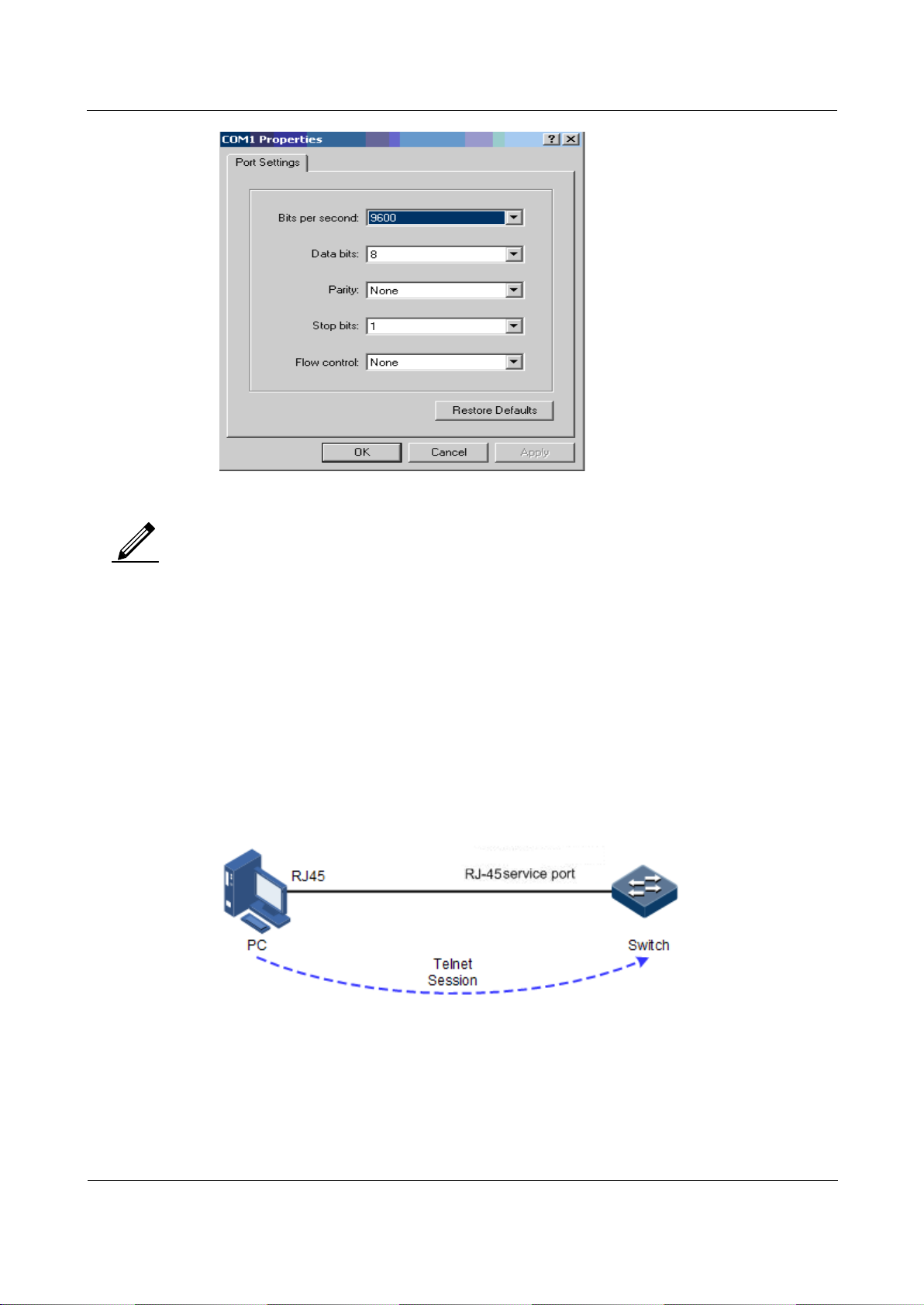
Orion Networks
A10E/A28E/A28F Configuration Guide
1 Basic configurations
Orion Networks
3
Note
Figure 1-2 Communication parameters configuration in Hyper Terminal
Microsoft is not in support of Hyper Terminal since Windows Vista system. For
Windows Vista or Windows 7, download Hyper Terminal program from internet. It is
free to download HyperTerminal program.
1.1.3 Accessing from Telnet
You can use a PC to log in to the A10E/A28E remotely through Telnet. You can log in to an
A10E/A28E from PC at first, then Telnet other A10E/A28E devices on the network. You do
not need to connect a PC to each A10E/A28E.
Telnet service provided by the A10E/A28E includes:
Telnet Server: run the Telnet client program on a PC to log in to the A10E/A28E, and
take configuration and management. As shown in Figure 1-3, the A10E/A28E is
providing Telnet Server service at this time.
Figure 1-3 Networking with the A10E/A28E as Telnet server
Before accessing the A10E/A28E through Telnet, you need to log in to the A10E/A28E
through the Console interface and start the Telnet service. Take the following configurations
on the A10E/A28E that needs to start Telnet service.
Page 24
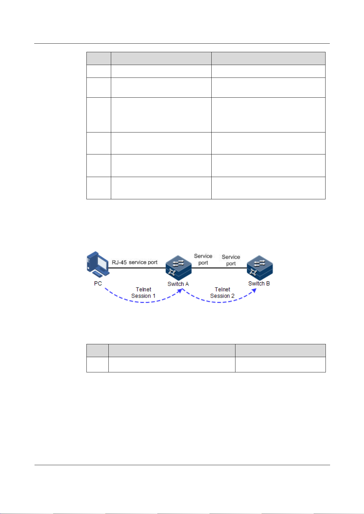
Orion Networks
A10E/A28E/A28F Configuration Guide
1 Basic configurations
Orion Networks
4
Step
Configuration
Description
1
Alpha-A28E#config
Enter global configuration mode.
2
Alpha-A28E(config)#interface
ip
if-number
Enter Layer 3 interface configuration
mode.
3
Alpha-A28E(config-ip)#ip
address
ip-address
[
ip-
mask
] [
vlan-id ]
Alpha-A28E(config-ip)#quit
Configure the IP address for the
A10E/A28E and bind the VLAN of
specified ID. This VLAN is used to open
the Telnet service interface.
4
Alpha-A28E(config)#telnetserver accept port-list
{ all |
port-list
}
(Optional) configure the interface in
support of Telnet function.
5
Alpha-A28E(config)#telnetserver close terminal-telnet
session-number
(Optional) release the specified Telnet
connection.
6
Alpha-A28E(config)#telnetserver max-session
session-
number
(Optional) configure device supports
maximal Telnet sessions.
Step
Configuration
Description
1
Alpha-A28E#telnet
ip-address
[ port
port-id
]
Log in to a device from Telnet.
Telnet Client: when you connect the A10E/A28E through the PC terminal emulation
program or Telnet client program on a PC, then telnet other A10E/A28E and
configure/manage them. As shown in Figure 1-4, Switch A not only acts as Telnet server
but also provides Telnet client service.
Figure 1-4 A10E/A28E as Telnet client networking
Configure Telnet Client device as below.
1.1.4 Accessing from SSHv2
Telnet is lack of security authentication and it transports packet by Transmission Control
Protocol (TCP) which exists with big potential security hazard. Telnet service may cause
hostile attacks, such as Deny of Service (DoS), host IP deceive, and routing deceiving.
The traditional Telnet and File Transfer Protocol (FTP) transmits password and data in
plaintext cannot satisfy users' security demands. SSHv2 is a network security protocol, which
can effectively prevent the disclosure of information in remote management through data
Page 25

Orion Networks
A10E/A28E/A28F Configuration Guide
1 Basic configurations
Orion Networks
5
Function
Default value
SSHv2 server function status
Disable
Local SSHv2 key pair length
512 bits
SSHv2 authentication method
password
SSHv2 authentication timeout
600s
Allowable failure times for SSHv2 authentication
20
SSHv2 snooping port number
22
SSHv2 session function status
Enable
Step
Configuration
Description
1
Alpha-A28E#config
Enter global configuration mode.
2
AlphaA28E(config)#generate
ssh-key [
length
]
Generate local SSHv2 key pair and designate its
length.
3
AlphaA28E(config)#ssh2
server
(Optional) start the SSHv2 server.
Use the no ssh2 server command to shut down the
SSHv2 server.
4
AlphaA28E(config)#ssh2
server authentication
{ password | rsakey }
(Optional) configure SSHv2 authentication mode.
5
AlphaA28E(config)#ssh2
server authentication
public-key
(Optional) type the public key of clients to the
A10E/A28E in rsa-key authentication mode.
6
AlphaA28E(config)#ssh2
server
authenticationtimeout
period
(Optional) configure SSHv2 authentication
timeout. The A10E/A28E refuses to authenticate
and then closes the connection when the client
authentication time exceeds this overtemperature
threshold.
encryption, and provides greater security for remote login and other network services in
network environment.
SSHv2 allows data to be exchanged via TCP and it builds up a secure channel over TCP.
Besides, SSHv2 supports other service ports besides standard port 22, thus to avoid illegal
attack from network.
Before accessing the A10E/A28E via SSHv2, you must log in to the A10E/A28E through
Console interface and starts up SSHv2 service.
The default configuration to accessing the A10E/A28E through SSHv2 is as follows.
Configure SSHv2 service for the A10E/A28E as below.
Page 26

Orion Networks
A10E/A28E/A28F Configuration Guide
1 Basic configurations
Orion Networks
6
Step
Configuration
Description
7
AlphaA28E(config)#ssh2
server
authenticationretries
times
(Optional) configure the allowable failure times
for SSHv2 authentication. The A10E/A28E refuses
to authenticate and then closes the connection
when client authentication failure numbers exceeds
this overtemperature threshold.
8
AlphaA28E(config)#ssh2
server port
port-id
(Optional) configure SSHv2 snooping port
number.
When configuring SSHv2 snooping port
number, the input parameter cannot take
effect until SSHv2 is restarted.
9
AlphaA28E(config)#ssh2
server session
session-list
enable
(Optional) enable SSHv2 session on the
A10E/A28E.
No.
Configuration
Description
1
Alpha-A28E#show telnet-server
Show configurations of the Telnet
server.
2
Alpha-A28E#show ssh2 public-key
[ authentication | rsa ]
Show the public key used for SSHv2
authentication on the A10E/A28E and
client.
3
Alpha-A28E#show ssh2 { server |
session }
Show SSHv2 server or session
information.
Note
1.1.5 Checking configurations
Use the following commands to check the configuration results.
1.2 CLI
1.2.1 Introduction
CLI is the path for communication between user and the A10E/A28E. You can complete
device configuration, monitor and management by executing relative commands.
You can log in to the A10E/A28E through PC that run terminal emulation program or the
CPE device, enter into CLI once the command prompt appears.
The features of CLI:
Local configuration via Console interface is available.
Page 27

Orion Networks
A10E/A28E/A28F Configuration Guide
1 Basic configurations
Orion Networks
7
Local or remote configuration via Telnet, Secure Shell v2 (SSHv2) is available.
Protection for different command levels, users in different level can only execute
commands in related level.
Different command types belong to different command modes. You can only execute a
type of configuration in its related command mode.
You can operate the commands by shortcut keys.
You can view or execute a historical command by transferring history record. The
A10E/A28E supports saving the latest 20 historical commands.
Online help is available by inputting "?" at any time.
Smart analysis methods such as incomplete matching and context association, etc.
facilitate user input.
1.2.2 Command line level
The A10E/A28E uses hierarchy protection methods to divide command line into 16 levels
from low to high.
0–4: visitor, users can execute the commands of ping, clear, and history, etc. in this
level;
5–10: monitor, users can execute the command of show and so on;
11–14: operator, users can execute commands for different services like VLAN, IP, etc.;
15: administrator, used for system basic running commands.
1.2.3 Command line mode
Command line mode is the CLI environment. All system commands are registered in one (or
some) command line mode, the command can only run under the corresponding mode.
Establish a connection with the A10E/A28E. If the A10E/A28E is in default configuration, it
will enter user EXEC mode, and the screen will display:
Alpha-A28E>
Input the enable command and correct password, and then enter privileged EXEC mode. The
default password is admin.
Alpha-A28E>enable
Password:
Alpha-A28E#
In privileged EXEC mode, input the command of config terminal to enter global
configuration mode.
Alpha-A28E#config terminal
Alpha-A28E(config)#
Page 28

Orion Networks
A10E/A28E/A28F Configuration Guide
1 Basic configurations
Orion Networks
8
Mode
Enter method
Description
User EXEC
Log in to the A10E/A28E, input
correct username and password
Alpha-A28E>
Privileged EXEC
In user EXEC mode, input the
enable command and correct
password.
Alpha-A28E#
Global configuration
In privileged EXEC mode, input
the config terminal command.
Alpha-A28E(config)#
Physical layer interface
configuration
In global configuration mode,
input the interface port port-id
command.
Alpha-A28E(configport)#
Layer 3 interface
configuration
In global configuration mode,
input the interface ip if-number
command.
Alpha-A28E(configip)#
VLAN configuration
In global configuration mode,
input the vlan vlan-id command.
Alpha-A28E(configvlan)#
Traffic classification
configuration
In global configuration mode,
input the class-map class-map-
name command.
Alpha-A28E(configcmap)#
Traffic policy
configuration
In global configuration mode,
input the policy-map policy-
map-name command.
Alpha-A28E(configpmap)#
Traffic policy
configuration binding
with traffic classification
In traffic policy configuration
mode, input the class-map class-
map-name command.
Alpha-A28E(configpmap-c)#
Access control list
configuration
In global configuration mode,
input the access-list-map acl-
number { deny | permit }
command.
Alpha-A28E(configaclmap)#
Note
Command line prompt "Alpha-A28E" is the default host name. You can use the
command of hostname string to modify the host name in privileged EXEC mode.
Some commands can be used both in global configuration mode and other modes,
but the accomplished functions are closely related to command line modes.
Generally, in a command line mode, you can go back to the previous level
command line mode by the command of quit or exit, but in the privileged EXEC
mode, you need to use disable command to go back to user EXEC mode.
Users can go back to privileged EXEC mode through the end command from any
command line mode except the user EXEC mode or privileged EXEC mode.
The A10E/A28E supports the following command line modes:
Page 29

Orion Networks
A10E/A28E/A28F Configuration Guide
1 Basic configurations
Orion Networks
9
Mode
Enter method
Description
Service instance
configuration
In global configuration mode,
input the service cisid level level
command.
Alpha-A28E(configservice)#
MST region
configuration
In global configuration mode,
input the spanning-tree region-
configuration command.
Alpha-A28E(configregion)#
Profile configuration
In global configuration mode,
input the igmp filter profile
profile-number command.
Alpha-A28E(configigmp-profile)#
Cluster configuration
In global configuration mode,
input the cluster command.
Alpha-A28E(configcluster)#
Shortcut
Description
Up cursor key (↑)
Show previous command if there is any command input
earlier; the display has no change if the current command is
the earliest one in history records.
Down cursor key (↓)
Show next command if there is any newer command; the
display has no change if the current command is the newest
one in history records.
Left cursor key (←)
Move the cursor one character to left; the display has no
change if the cursor is at the beginning of command.
Right cursor key (→)
Move the cursor one character to right; the display has no
change if the cursor is at the end of command.
Backspace
Delete the character before the cursor; the display has no
change if the cursor is at the beginning of command.
Tab
Click Tab after inputting a complete keyword, cursor will
automatically appear a space to the end; click Tab again, the
system will show the follow-up inputting keywords.
Click Tab after inputting an incomplete keyword, system
automatically executes partial helps:
System take the complete keyword to replace input if the
matched keyword is the one and only, and leave one word
space between the cursor and end of keyword;
In case of mismatch or matched keyword is not the one and
only, display prefix at first, then click Tab to check words
circularly, no space from cursor to the end of keyword, click
Space key to input the next word;
If input incorrect keyword, click Tab will change to the
next line and prompt error, the input keyword will not
change.
1.2.4 Command line shortcuts
The A10E/A28E supports the following command line shortcuts:
Page 30

Orion Networks
A10E/A28E/A28F Configuration Guide
1 Basic configurations
Orion Networks
10
Shortcut
Description
Ctrl+A
Move the cursor to the head of line.
Ctrl+C
Break off some running operation, such as ping, traceroute
and so on.
Ctrl+D or Delete
Delete the cursor location characters
Ctrl+E
Move the cursor to the end of line.
Ctrl+K
Delete all characters behind the cursor (including cursor
location).
Ctrl+X
Delete all characters before the cursor (except cursor
location).
Ctrl+Z
Return to privileged EXEC mode from other modes (except
user EXEC mode).
Space or y
When the terminal printing command line information
exceeds the screen, continue to show the information in next
screen.
Enter
When the terminal printing command line information
exceeds the screen, continue to show the information in next
line.
1.2.5 Command line help message
Complete help
You can get complete help in the below three conditions:
Click "?" in any command mode to get all commands and their brief description under
the command view.
Alpha-A28E>?
The command output is as below.
clear Clear screen
enable Turn on privileged mode command
exit Exit current mode and down to previous mode
help Message about help
history Most recent historical command
language Language of help message
list List command
quit Exit current mode and down to previous mode
terminal Configure terminal
test Test command .
Page 31

Orion Networks
A10E/A28E/A28F Configuration Guide
1 Basic configurations
Orion Networks
11
Input a command and followed by a "?" after one character space, if the position of "?" is
keyword, list all keyword and brief description.
Alpha-A28E(config)#ntp ?
The command output is as below.
peer Configure NTP peer
refclock-master Set local clock as reference clock
server Configure NTP server
Input a command and followed by a "?" after one character space, if the position of "?" is
parameter, list the range and brief description.
Alpha-A28E(config)#interface ip ?
Partial help
The command output is as below.
<0-14> IP interface number
You can get partial help in the below three conditions:
Input a character string and start with a "?", the A10E/A28E will list all keywords
starting with the character string under current mode.
Alpha-A28E(config)#c?
The command output is as below.
class-map Set class map
clear Clear screen
console-cli Console CLI
cpu Configure cpu parameters
create Create static VLAN
Input a command and followed by a character string with "?", the A10E/A28E will list
all keywords start with the character string in the command of current mode.
Page 32

Orion Networks
A10E/A28E/A28F Configuration Guide
1 Basic configurations
Orion Networks
12
Shortcut
Description
% " * " Incomplete command..
User inputs incomplete command.
% Invalid input at '^' marked.
Keyword marked "^" are invalid or do not exist.
% Ambiguous input at '^' marked,
follow keywords match it.
Keyword marked with "^" is not clear.
% Unconfirmed command.
The command line input by the user is not
unique.
% Unknown command.
The command line input by the user does not
exist.
% You Need higher priority!
The user does not have enough right to execute
the command line.
Note
Alpha-A28E(config)#show li?
The command output is as below.
link-admin-status link administrator status
link-state-tracking Link state tracking
Input the first few letters of a command keyword and click Tab to show complete
keyword. The precondition is the input letters can identify the keyword clearly, otherwise,
different keywords will be shown circularly after click Tab, you can choose the right
keyword from them.
Error prompt message
The A10E/A28E prints out the following error prompt according to error type when you input
incorrect commands.
If there is error prompt message mentioned above, please use the command line
help message to solve the problem.
1.2.6 CLI message
Displaying characteristics
CLI provides the following display characteristics:
The help message and prompt message in CLI are displayed in both Chinese and English
languages.
Page 33

Orion Networks
A10E/A28E/A28F Configuration Guide
1 Basic configurations
Orion Networks
13
Function key
Description
Press Space or y
Continue to display next screen message
Press Enter
Continue to display next line message
Press any letter key (except y)
Stop the display and command execution
Step
Configuration
Description
1
Alpha-A28E#terminal pagebreak enable
Enable display message page-break
function
Provide pause function when one time display message exceeds one screen, you have the
following options at this time, as shown below.
Table 1-1 Function keys description for command line message display characteristics
Filtering displayed information
The A10E/A28E supports a series commands starting with show, for checking device
configuration, operation and diagnostic information. Generally speaking, these commands can
output more information, and then user needs to add filter rules to filter out unnecessary
information.
The show command of the A10E/A28E supports three kinds of filter modes:
| begin string: show all lines starting from the assigned string;
| exclude string: show all lines mismatch with the assigned string;
| include string: show all lines only match with the assigned string.
Terminal page-break
Terminal page-break refers to the pause function when displayed message exceeds one screen,
you can use the display function keys in Table 1-1 to control message display. If message
page-break is disabled, it will not provide pause function when displayed message exceeds
one screen; all the messages will be displayed circularly at one time.
By default, terminal page-break is enabled.
Configure the A10E/A28E as below.
1.2.7 Command line history message
Command line interface can save the user historical command automatically; you can use the
up cursor key (↑) or down cursor key (↓) to call the historical command saved by command
line repeatedly at any time.
By default, the system saves the recent 20 historical commands in the cache. You can set the
number of system stored historical command.
Configure the A10E/A28E as below.
Page 34

Orion Networks
A10E/A28E/A28F Configuration Guide
1 Basic configurations
Orion Networks
14
Step
Configuration
Description
1
Alpha-A28E>terminal history
number
(Optional) configure the number of
system stored historical command.
2
Alpha-A28E>terminal time-out
period
(Optional) configure the Console
terminal timeout period.
3
Alpha-A28E>enable
Enter privileged EXEC mode.
4
Alpha-A28E#history
Show historical commands input by
the user.
5
Alpha-A28E#show terminal
Show terminal configurations by the
user.
Note
1.2.8 Restoring default value of command line
The default value of command line can be restored by no format or enable | disable format.
no option: providing in the front of command line to restore the default value, disable
some function, delete some setting, etc.; perform some operations opposite to command
itself. Commands with no option are also known as reverse commands.
enable | disable option: providing in the back or center of command line; enable is to
enable some feature or function, while disable is to prohibit some feature or function.
For example:
Perform description text command in physical layer interface mode to modify the
interface description; perform no description command to delete the interface description
and restore the default values.
Use the shutdown command in physical layer interface mode to disable an interface; use
the no shutdown command to enable an interface.
Use the shutdown command in global configuration mode to disable an interface; use
the no shutdown to enable an interface.
Use the terminal page-break enable command in global configuration mode to enable
terminal page-break; use the terminal page-break disable command to disable terminal
page-break.
Most configuration commands have default values, which often are restored by no
option.
1.3 Managing users
When you start the A10E/A28E for the first time, connect the PC through Console interface to
the A10E/A28E, input the initial user name and password in HyperTerminal to log in and
configure the A10E/A28E.
Page 35

Orion Networks
A10E/A28E/A28F Configuration Guide
1 Basic configurations
Orion Networks
15
Step
Configuration
Description
1
Alpha-A28E#user name
user-name
password
password
Create or modify the user name and password.
2
Alpha-A28E#user name
user-name
privilege
privilege-level
Configure login user privilege. The initial user
privilege is 15, which is the highest privilege.
3
Alpha-A28E#user
user-
name
{ allow-exec |
disallow-exec }
first-keyword
[
second-keyword
]
Configure the priority rule for login user to perform
the command line.
Specified allow-exec parameters will allow the user
to perform commands higher than the current
priority.
Specified disallow-exec parameter will allow the
user to perform commands lower than the current
priority only.
No.
Configuration
Description
1
Alpha-A28E#show user [ detail ]
Show information about the login
users
Note
Initially, both the user name and password are admin
If there is not any privilege restriction, any remote user can log in to the A10E/A28E via
Telnet or access network by building Point to Point Protocol (PPP) connection when the
Simple Network Management Protocol (SNMP) interface or other service interface of the
A10E/A28E are configured with IP address. This is unsafe to the A10E/A28E and network.
Creating user for the A10E/A28E and setting password and privilege help manage the login
users and ensures network and device security.
Configure login user management for the A10E/A28E of as below.
1.3.1 Checking configurations
Use the following commands to check configuration results.
1.4 Managing files
1.4.1 Managing BootROM files
The BootROM file is used to boot the A10E/A28E and finish device initialization. You can
upgrade the BootROM file through File Transfer Protocol (FTP) FTP or Trivial File Transfer
Protocol (TFTP). By default, the name of the BootROM file is bootrom or bootromfull.
After powering on the A10E/A28E, run the BootROM files at first, click Space to enter
BootROM menu when the prompt "Press space into Bootrom menu…" appears:
Page 36

Orion Networks
A10E/A28E/A28F Configuration Guide
1 Basic configurations
Orion Networks
16
Operation
Description
?
List all executable operations.
b
Quick execution for system bootrom software.
E
Format the memory of the A10E/A28E.
h
List all executable operations.
u
Download the system startup file through the XMODEM.
N
Set Medium Access Control (MAC) address.
R
Reboot the A10E/A28E.
T
Download the system startup software through TFTP and replace it.
V
Show device BootROM version.
Step
Configuration
Description
1
Alpha-A28E#download bootstrap { ftp
ip-address user-name password filename
| tftp
ip-address file-name
}
(Optional) download the
BootROM file through FTP or
TFTP.
begin...
ram size: 64M DDR testing...done
File System Version:1.0
Init flash ...Done
Bootstrap_3.1.6.Alpha-A28E.1.20130729, Orion Networks Compiled Jul 29
2013, 18:37:36
Base Ethernet MAC address: f8:f0:82:99:99:99
Press space into Bootstrap menu...
4
In Boot mode, you can do the following operations.
System files are the files needed for system operation (like system startup software,
configuration file). These files are usually saved in the memory, the A10E/A28E manages
them by a file system to facilitate user manage the memory. The file system contains
functions of creating, deleting and modifying file and directory.
Besides, the A10E/A28E supports dual system; that is to say, it can store two versions of
system software in memory. You can shift to the other version when one version cannot work
due to system upgrade failure.
Configure system files management for the A10E/A28E as below.
All the following steps are optional and no sequencing.
Page 37

Orion Networks
A10E/A28E/A28F Configuration Guide
1 Basic configurations
Orion Networks
17
Step
Configuration
Description
2
Alpha-A28E#download system-boot
{ ftp
ip-address user-name password
file-name
| tftp
ip-address file-
name
}
(Optional) download the
system startup file through
FTP or TFTP.
3
Alpha-A28E#upload system-boot { ftp
[
ip-address user-name password
file-name
] | tftp [
ip-address
file-name
] }
(Optional) upload the system
startup file through FTP or
TFTP.
4
Alpha-A28E#erase [
file-name
]
(Optional) delete files saved in
the memory.
Step
Configuration
Description
1
Alpha-A28E#download system
[ master | slave ] { ftp
ipaddress user-name password filename
| sftp
ip-address user-name
password file-name
| tftp
ip-
address file-name
}
(Optional) download the system boot
file through FTP or TFTP.
2
Alpha-A28E#erase [
file-name
]
(Optional) delete files saved in the
flash.
1.4.2 Managing system files
Configuration files are loaded after starting the system; different files are used in different
scenarios in order to achieve different service functions. After starting the system, you can
configure the A10E/A28E and save the configuration files. New configuration will take effect
in next boot.
Configuration file has an affix ".cfg", and these files can be open by text book program in
Windows system. The contents in the following format:
Saved as Mode+Command format;
Just reserve the non-defaulted parameters to save space (refer to command reference for
default values of configuration parameters);
Take the command mode for basic frame to organize commands, put commands of one
mode together to form a section, the sections are separated by "!".
The A10E/A28E starts initialization by reading configuration files from memory after
powering on. Thus, the configuration in configuration files are called initialization
configuration. If there is no configuration files in memory, the A10E/A28E takes the default
parameters for initialization.
The configuration that is currently used by the A10E/A28E is called running configuration.
You can modify the A10E/A28E current configuration through command line. The current
configuration can be used as initial configuration when next time power on, user must use the
write command to save current configuration into memory and form configuration file.
Configure the configuration files management for the A10E/A28E as below.
Page 38

Orion Networks
A10E/A28E/A28F Configuration Guide
1 Basic configurations
Orion Networks
18
Step
Configuration
Description
3
Alpha-A28E#upload system
[ master | slave ] { ftp
ipaddress user-name password filename
| sftp
ip-address user-name
password file-name
| tftp
ip-
address file-name
}
(Optional) upload the system boot file
through FTP or TFTP.
Step
Configuration
Description
1
Alpha-A28E#download startupconfig { ftp [
ip-address user-
name password file-name
]
[ reservedevcfg ] | tftp [
ip-
address file-name
]
[ reservedevcfg ] }
(Optional) download the startup
configuration file through FTP or
TFTP.
2
Alpha-A28E#erase [
file-name
]
(Optional) delete files saved in the
memory.
3
Alpha-A28E#upload startup-config
{ ftp [
ip-address user-name
password file-name
] | tftp [
ip-
address file-name
] }
(Optional) upload the startup
configuration file through FTP or
TFTP.
4
Alpha-A28E#write
(Optional) save the running
configuration file into the memory.
1.4.3 Managing configuration files
Configuration files are loaded after starting the system; different files are used in different
scenarios in order to achieve different service functions. After starting the system, you can
configure the A10E/A28E and save the configuration files. New configuration will take effect
in next boot.
Configuration file has an affix ".cfg", and these files can be opened by text program in
Windows system. The contents in the following format:
Saved as Mode+Command format.
Just reserve the non-defaulted parameters to save space (refer to command reference for
default values of configuration parameters).
Take the command mode for basic frame to organize commands, put commands of one
mode together to form a section, the sections are separated by "!".
The A10E/A28E starts initialization by reading configuration files from memory after
powering on. Thus, the configuration in configuration files are called initial configuration. If
there is no configuration files in memory, the A10E/A28E take the default parameters for
initialization.
The configuration that is currently used by the A10E/A28E is called running configuration.
You can modify the A10E/A28E current configuration through CLI. The running
configuration can be used as initial configuration when next time power on, you must use
command write to save current configuration into memory and form configuration file.
Configure the configuration files management for the A10E/A28E as below.
Page 39

Orion Networks
A10E/A28E/A28F Configuration Guide
1 Basic configurations
Orion Networks
19
No.
Item
Description
1
Alpha-A28E#show startup-config
[
file-name
]
Show configuration information loaded
upon device startup.
2
Alpha-A28E#show running-config
[ interface port [
port-id
] ]
Show the running configuration
information.
Function
Default value
System time
2000-01-01 08:00:00.000
System clock mode
default
System belonged time zone
UTC+8
Time zone offset
+08:00
Functional status of Daylight Saving Time
Disable
Step
Configuration
Description
1
Alpha-A28E#clock set
hour minute
second year month day
Configure system time.
2
Alpha-A28E#clock timezone { + |
- }
hour minute timezone-name
Configure system belonged time zone.
3
Alpha-A28E#clock mode
{ auxiliary | default |
timestamp }
Configure system clock mode.
1.4.4 Checking configurations
Use the following commands to check configuration results.
1.5 Configuring clock management
1.5.1 Configuring time and time zone
To ensure the A10E/A28E to work well with other devices, you must configure system time
and belonged time zone accurately.
The A10E/A28E supports three types of system time mode, which are time stamp mode,
auxiliary time mode, and default mode from high to low according to timing unit accuracy.
You need to select the most suitable system time mode by manual in accordance with actual
application environment.
The default configuration of time and time zone is as below.
Configure time and time zone for the A10E/A28E as below.
Page 40

Orion Networks
A10E/A28E/A28F Configuration Guide
1 Basic configurations
Orion Networks
20
Step
Configuration
Description
1
Alpha-A28E#clock summer-time enable
Enable DST.
Use the clock summer-time
disable command to disable this
function.
2
Alpha-A28E#clock summer-time
recurring {
week
| last } { fri |
mon | sat | sun | thu | tue | wed }
month hour minute
{
week
| last }
{ fri | mon | sat |sun | thu | tue
| wed }
month hour minute offset-mm
Configure calculation period for
system DST.
Note
1.5.2 Configuring DST
Daylight Saving Time (DST) is a kind of artificial regulation local time system for saving
energy. At present, there are nearly 110 countries operating DST every summer around the
world, but different countries have different stipulations for DST. Thus, you should consider
the local conditions when configuring DST.
Configure DST for the A10E/A28E as below.
When you set system time manually, if the system uses DST, such as DST from 2
a.m. on the second Sunday, April to 2 a.m. on the second Sunday, September
every year, you have to advance the clock one hour faster during this period, set
time offset as 60 minutes and from 2 a.m. to 3 a.m. on the second Sunday, April
each year is an inexistent time. The time setting by manual operation during this
period shows failure.
The summer time in southern hemisphere is opposite to northern hemisphere,
which is from September to April of next year. If user configures start time later
than ending time, system will suppose it is in the Southern Hemisphere. That is to
say, the summer time is the start time this year to the ending time of next year.
1.5.3 Configuring NTP
Network Time Protocol (NTP) is a time synchronization protocol defined by RFC1305, used
to synchronize time between distributed time servers and clients. NTP transportation is based
on UDP, using port 123.
The purpose of NTP is to synchronize all clocks in a network quickly and then the
A10E/A28E can provide different application over a unified time. Meanwhile, NTP can
ensure very high accuracy, with accuracy of 10ms around.
The A10E/A28E in support of NTP cannot only accept synchronization from other clock
source, but also to synchronize other devices as a clock source.
The A10E/A28E adopts multiple NTP working modes for time synchronization:
Server/Client mode
In this mode, client sends clock synchronization message to different servers. The server
works in server mode by automation after receiving synchronization message and send
Page 41

Orion Networks
A10E/A28E/A28F Configuration Guide
1 Basic configurations
Orion Networks
21
Function
Default value
Whether the A10E/A28E is NTP master clock
no
Global NTP server
inexistent
Global NTP equity
inexistent
Reference clock source
0.0.0.0
Step
Configuration
Description
1
Alpha-A28E#config
Enter global configuration mode.
2
Alpha-A28E(config)#ntp
server
ip-address
[ version
[ v1 | v2 | v3 ] ]
(Optional) configure NTP server address
for client device working in server/client
mode.
3
Alpha-A28E(config)#ntp peer
ip-address
[ version [ v1 |
v2 | v3 ] ]
(Optional) configure NTP equity address
for the A10E/A28E working in symmetric
peer mode.
4
Alpha-A28E(config)#ntp
refclock-master [
ip-
address
] [
stratum
]
Configure clock of the A10E/A28E as
NTP reference clock source for the
A10E/A28E.
Note
answering message. The client received answering message and perform clock filer and
selection, then synchronize it to privileged server.
In this mode, client can synchronize to server but the server cannot synchronize to client.
Symmetric peer mode
In this mode, active equity send clock synchronization message to passive equity. The passive
equity works in passive mode by automation after receiving message and send answering
message back. By exchanging messages, the two sides build up symmetric peer mode. The
active and passive equities in this mode can synchronize each other.
The NTP default configuration is as below.
Configure NTP for the A10E/A28E as below.
If the A10E/A28E is configured as NTP reference clock source, the NTP server or
NTP equity are not configurable; and vice versa, the A10E/A28E cannot be
configured as NTP reference clock if the NTP server or equity are configured.
1.5.4 Configuring SNTP
Simple Network Time Protocol (SNTP) is mainly used to synchronize Switch system time
with the SNTP device time in the network. The time synchronized by SNTP protocol is
Greenwich Mean Time (GMT), which can be changed to local time according to system
setting of time zone.
Page 42

Orion Networks
A10E/A28E/A28F Configuration Guide
1 Basic configurations
Orion Networks
22
Function
Default value
SNTP server address
inexistent
Step
Configuration
Description
1
Alpha-A28E#config
Enter global configuration mode.
2
AlphaA28E(config)#sntp
server
ip-address
(Optional) configure the IP address of the SNTP server
which works in server/client mode.
No.
Item
Description
1
Alpha-A28E#show clock
[ summer-time-recurring ]
Show the A10E/A28E system time, time
zone and DST configuration.
2
Alpha-A28E#show sntp
Show SNTP configurations.
3
Alpha-A28E#show ntp status
Show NTP configurations.
4
Alpha-A28E#show ntp
associations [ detail ]
Show NTP connection information.
Function
Default value
Maximum forwarding frame length of interface
9712 Bytes
Duplex mode of interface
Auto-negotiation
Note
The SNTP default configuration is as below.
Configure SNTP for the A10E/A28E as below.
After configuring SNTP server address, the A10E/A28E will try to get clock
information from SNTP server every 3s, and the maximum timeout for clock
information is 10s.
1.5.5 Checking configurations
Use the following commands to check configuration results.
1.6 Configuring interface management
1.6.1 Default configurations of interfaces
The default configuration of physical layer interface is as below.
Page 43

Orion Networks
A10E/A28E/A28F Configuration Guide
1 Basic configurations
Orion Networks
23
Function
Default value
Interface speed
Auto-negotiation
Interface flow control status
Disable
Optical/Electrical mode of the Combo interface
Automatical
Flow control of the Combo interface
Disable
Time interval of interface dynamic statistics
2s
Interface status
Enable
Step
Configuration
Description
1
Alpha-A28E#config
Enter global configuration mode.
2
AlphaA28E(config)#inte
rface port
port-
id
Enter physical layer interface configuration mode.
3
AlphaA28E(configport)#flowcontrol
{ off | on }
Enable/Disable flow control of 802.3x packets on the
interface.
Step
Configuration
Description
1
Alpha-A28E#config
Enter global configuration mode.
2
Alpha-A28E(config)#interface
port
port-id
Enter physical layer interface
configuration mode.
3
Alpha-A28E(configport)#flowcontrol { off | on }
Enable/Disable flow control over
802.3x packet on the interface.
1.6.2 Configuring basic attributes for interfaces
The interconnected devices cannot communicate normally if their interface attributes (such as
MTU, duplex mode, and speed) are inconsistent, and then you have to adjust the interface
attribute to make the devices at both ends match each other.
Configure the basic attributes for interface of the A10E/A28E.
1.6.3 Configuring flow control on interfaces
IEEE802.3x is flow control of full-duplex Ethernet data layer. Then the client sends request to
the server; the client sends PAUSE frame to server if there is system or network jam, so it
delays data transmission from server to client.
Configure flow control for the A10E/A28E as below.
Page 44

Orion Networks
A10E/A28E/A28F Configuration Guide
1 Basic configurations
Orion Networks
24
Step
Configuration
Description
1
Alpha-A28E#config
Enter global configuration mode.
2
Alpha-A28E(config)#interface
port
port-id
Enter physical layer interface
configuration mode.
3
Alpha-A28E(config-port)#mediapriority { fiber | copper }
Configure Combo interface
optical/electrical priority.
Optical/electrical priority selection
function can select to use optical port
or electrical port in prior when
inserting optical port or electrical port
at the same time.
4
Alpha-A28E(configport)#description medium-type
{ fiber | copper }
word
Configure Combo interface
optical/electrical description
information.
5
Alpha-A28E(config-port)#speed
medium-type { fiber | copper }
{ auto | 10 | 100 | 1000 }
Configure Combo interface
optical/electrical transmission speed.
The interface speed also depended on
the module specification used.
6
Alpha-A28E(config-port)#duplex
medium-type copper { full |
half }
Configure Combo interface electrical
duplex mode.
7
Alpha-A28E(config-port)#mdi
medium-type copper { auto |
normal | across }
Configure Combo interface as
electrical port MDI mode.
8
Alpha-A28E(configport)#flowcontrol medium-type
{ fiber | copper } { on | off }
Configure Combo interface
optical/electrical flow control.
1.6.4 Configuring the Combo interface
The A10E/A28E Combo interface supports both optical module and electrical module, so
transmission media can be optical fiber or cable according to interface media type supported
by the peer device. If using both two kinds of transmission media for connection, service
transmission can only use one of them at the same time.
The Combo interface has two modes to select transmission media: mandatory and automatic.
If the configuration mode is automatic selection and two kinds of transmission medium of
optical fiber and cable connections are normal, the interface will automatically choose one of
them as an effective transmission line as well as automatically select another transmission
medium for service transmission when current transmission medium breaks down.
In auto-selection mode, after the Combo optical interface and Combo electrical interface are
configured respectively, the device automatically use the optical/electrical interface if needed,
without configuring them every time upon use.
Configure the Combo interface for the A10E/A28E as below.
1.6.5 Configuring interface rate statistics
Configure the A10E/A28E as below.
Page 45

Orion Networks
A10E/A28E/A28F Configuration Guide
1 Basic configurations
Orion Networks
25
Step
Configuration
Description
1
Alpha-A28E#config
Enter global configuration mode.
2
AlphaA28E(config)#interface port
port-id
Enter physical layer interface configuration
mode.
3
Alpha-A28E(config-port)#sfp
detect-mode { auto-detect |
force-100base-x | force1000base-x }
Configure SFP interface detection mode.
Non-SFP interfaces cannot be configured
with detection mode.
Step
Configuration
Description
1
Alpha-A28E#config
Enter global configuration mode.
2
Alpha-A28E(config)#dynamic
statistics time
period
Configure period for interface dynamic
statistics.
By default, it is 2s.
3
Alpha-A28E(config)#clear
interface port
port-id
statistics
Clear interface statistics saved on the
A10E/A28E.
Step
Configuration
Description
1
Alpha-A28E#config
Enter global configuration mode.
2
Alpha-A28E(config)#interface
port
port-id
Enter physical layer interface
configuration mode.
3
Alpha-A28E(configport)#shutdown
Disable current interface.
Use the command of no shutdown to re-
open the closed interface.
No.
Item
Description
1
Alpha-A28E#show interface port [
port-
id
]
Show interface status.
1.6.6 Configuring interface statistics
Configure the A10E/A28E as below.
1.6.7 Enabling/Disabling interfaces
Configure the A10E/A28E as below.
1.6.8 Checking configurations
Use the following commands to check configuration results.
Page 46

Orion Networks
A10E/A28E/A28F Configuration Guide
1 Basic configurations
Orion Networks
26
No.
Item
Description
2
Alpha-A28E#show interface port
port-id
statistics dynamic [ detail ]
Show interface statistics.
3
Alpha-A28E#show interface port [
port-
id
] flowcontrol
Show flow control on the
interface.
4
Alpha-A28E#show system mtu
Show system MTU.
5
Alpha-A28E#show combo description port
[
port-id
]
Show information about the
Combo interface.
6
Alpha-A28E#show combo configuration
port [
port-id
]
Show configurations of the
Combo interface.
7
Alpha-A28E#show sfp detect-mode port
[
port-id
]
Show detection mode of the
SFP interface.
Step
Configuration
Description
1
AlphaA28E#hostname
name
(Optional) configure device name.
By default, the device name is Alpha-A28E.
The system supports changing device name to make users
distinguish different devices in the network. Device name
become effective immediately, which can be seen in terminal
prompt.
2
AlphaA28E#language
{ chinese |
english }
(Optional) configure switchover language mode.
By default, the language is English.
The system supports displaying help and prompt information
is both English and Chinese.
3
AlphaA28E#write
Save configuration.
Save configuration information to the A10E/A28E after
configuration, and the new saved configuration information
will cover the original configuration information.
Without saving, the new configuration information will lose
after rebooting, and the A10E/A28E will continue working
with the original configuration.
Use the command of erase file-name to delete the
configuration file. This operation cannot be restored,
so use this command with care.
1.7 Configuring basic information
Configure the A10E/A28E as below.
Page 47

Orion Networks
A10E/A28E/A28F Configuration Guide
1 Basic configurations
Orion Networks
27
Step
Configuration
Description
4
AlphaA28E#reboot
[ now ]
(Optional) configure reboot options.
When the A10E/A28E is in failure, please reboot it to solve
the problem according to actual condition.
5
AlphaA28E#erase
[
file-name
]
(Optional) delete files saved in the memory.
Step
Configuration
Description
1
Alpha-A28E#config
Enter global configuration
mode.
2
Alpha-A28E(config)#schedule-list
list-
number
start { date-time
month-day-year
hour:minute:second
[ every { day | week |
period hour:minute:second
} ] stop month-
day-year
hour:minute:second
| up-time
period hour:minute:second
[ every
period
hour:minute:second
] [ stop
period
hour:minute:second
] }
Create and configure
schedule list.
3
Alpha-A28E(config)#
command-string
schedule-list
list-number
Bind the command line
which needs periodic
execution and supports
schedule list to the
schedule list.
4
Alpha-A28E#show schedule-list [
list-
number
]
Show configurations of
the schedule list.
1.8 Task scheduling
When you need to use some commands periodically or at a specified time, configure task
scheduling.
The A10E/A28E supports realizing task scheduling by combining the program list to
command line. You just need to designate the task start time, period and end time in the
program list, and then bind the program list to command line so as to realize the periodic
operation of command line.
Configure task scheduling for the A10E/A28E as below.
1.9 Watchdog
The interference of outside electromagnetic field will influence the working of single chip
microcomputer, and cause program fleet and dead circulation so that the system cannot work
normally. Considering the real-time monitoring to the running state of single chip
Page 48

Orion Networks
A10E/A28E/A28F Configuration Guide
1 Basic configurations
Orion Networks
28
Step
Configuration
Description
1
Alpha-A28E#watchdog enable
Enable watchdog.
2
Alpha-A28E#show watchdog
Show watchdog status.
microcomputer, it generates a program specially used to monitoring the running status of
switch hardware, which is commonly known as the Watchdog.
The system will reboot when the Switch cannot continue to work for task suspension or dead
circulation, and without feeding the dog within a feeding dog cycle.
The watchdog function configuration can prevent the system program from dead circulation
caused by uncertainty fault so as to improve the stability of system.
Configure the A10E/A28E as below.
1.10 Load and upgrade
1.10.1 Introduction
Load
Upgrade
In traditional, configuration files are loaded by serial port, it takes a long time to load for the
low speed and remote loading is unavailable. FTP and TFTP loading modes can solve those
problems and make operation more convenient.
The A10E/A28E supports TFTP auto-loading mode.
TFTP auto-loading means users get the device configuration files from server and then
configure the device. Auto-loading function allows configuration files to contain loading
related commands for multiple configurations loading so as to meet file auto-loading
requirements in complex network environment.
The A10E/A28E provides several methods to confirm configuration file name in TFTP server,
such as input by manual, obtain by DHCP Client, use default configuration file name, etc.
Besides, users can assign certain denomination rule for configuration files and then, the
device confirms the name according to the rules and combines with itself attribution (device
type, MAC address, software version, and so on).
The A10E/A28E needs to upgrade if you want to add new features, optimize functions or
solve current software version bugs.
The A10E/A28E supports the following two upgrade modes:
Upgrade by BootROM
Upgrade by command line
Page 49

Orion Networks
A10E/A28E/A28F Configuration Guide
1 Basic configurations
Orion Networks
29
No.
Item
Description
1
Alpha-A28E#config
Enter global configuration mode.
2
AlphaA28E(config)#service
config tftp-server
ip-
address
Configure the IP address of the TFTP server. By
default, this address is not configured.
3
AlphaA28E(config)#service
config filename rule
[
rule-number
]
Set naming convention rule for file name. By
default, there is no naming convention, and the
system uses default file name as
startup_config.conf.
4
AlphaA28E(config)#service
config filename
file-
name
Specify the name of the configuration file to be
uploaded.
5
AlphaA28E(config)#service
config version { systemboot | bootstrap |
startup-config }
version
Configure file version No.
6
AlphaA28E(config)#service
config overwrite enable
Enable local configuration file overwriting.
7
AlphaA28E(config)#service
config
Enable configuration auto-loading.
8
AlphaA28E(config)#service
config trap enable
Enable Trap function.
Note
1.10.2 Configuring TFTP auto-upload method
You need to build TFTP environment before configuring TFTP auto-upload method to have
the A10E/A28E interconnect with TFTP server.
When you perform configuration auto-loading function, the IP address priority
configured by commands is higher than the one obtained by DHCP Client.
When you perform configuration auto-loading function, configuration file name
obtained from server in priority turn from higher to lower as file name confirmed by
naming convention > file name configured by command > file name obtained by
DHCP Client.
Configure TFTP auto-loading for the A10E/A28E as below.
1.10.3 Upgrading system software by BootROM
In the below conditions, user needs to upgrade system software by BootROM:
The device is started for the first time.
A system file is damaged.
Page 50

Orion Networks
A10E/A28E/A28F Configuration Guide
1 Basic configurations
Orion Networks
30
Step
Operation
1
Log in device through serial port as administrator and enter Privileged EXEC
mode, reboot the A10E/A28E by the command of reboot.
Alpha-A28E#reboot
Please input 'yes' to confirm:yes
Rebooting ...
2
Click Space key to enter interface when the display shows "Press space into
Bootstrap menu...", then input "?" to display command list:
[Alpha-A28E]:?
? - List all available commands
h - List all available commands
V - Show bootstrap version
b - Boot an executable image
E - Format both DOS file systems
T - Download system program
u - XMODEM download system boot image
N - set ethernet address
R - Reboot
The input letters are case sensitive.
The card cannot start up in order.
Before upgrading system software by BootROM, you should build FTP environment, take the
PC as FTP server and the A10E/A28E as client. Basic requirements are as below.
Configure FTP server, make sure the server is available.
Configure IP address for TFTP server; keep it in the same network segment with
A10E/A28E IP address.
Steps for upgrading system software by BootROM:
Page 51

Orion Networks
A10E/A28E/A28F Configuration Guide
1 Basic configurations
Orion Networks
31
Step
Operation
3
Input "T" to download system boot file through TFTP. The system displays the
following information.
[Alpha-A28E]:T
dev name:et
unit num:1
file name: system_boot.Z NOS_4.14.1921.Alpha-A28E.000.20130729
local ip: 192.168.1.1 192.168.18.250
server ip: 192.168.1.2 192.168.18.16
user:wrs 1
password:wrs 123456
Loading... Done
Saving file to flash...
Ensure the input file name here is correct, the file name should not be
longer than 80 characters.
4
Input "b" to quick execute bootstrap file. The A10E/A28E will reboot and load
the downloaded system boot file.
No.
Item
Description
1
Alpha-A28E#download system-boot
{ ftp [
ip-address user-name
password file-name
] | tftp
[
ip-address file-name
] }
Download system boot file through
FTP/TFTP.
2
Alpha-A28E#write
Write the configured file into the
memory.
3
Alpha-A28E#reboot [ now ]
Reboot the A10E/A28E, and it will
automatically load the downloaded
system boot file.
1.10.4 Upgrading system software by CLI
Before upgrading system software by command line, you should build FTP/TFTP
environment, take the PC as FTP/TFTP server and the A10E/A28E as client. Basic
requirements are as below.
The A10E/A28E connects to the TFTP server.
Configure the FTP/TFTP server. Ensure the server is available.
Configure IP address for FTP/TFTP server to make sure that A10E/A28E can access the
server.
Upgrade system software through CLI as below.
Page 52

Orion Networks
A10E/A28E/A28F Configuration Guide
1 Basic configurations
Orion Networks
32
No.
Item
Description
1
Alpha-A28E#show service
config
Show auto-configured loading information.
2
Alpha-A28E#show service
config filename rule
rule-
number
Show naming convention for configuration
files.
3
Alpha-A28E#show version
Show system version.
1.10.5 Checking configurations
Use the following commands to check configuration results.
1.10.6 Exampe for configuring TFTP auto-loading
Networking requirements
As shown in Figure 1-5, connect the TFTP server with the switch, and configure auto-loading
function on the switch to make the switch automatically load configuration file from TFTP
server. Hereinto, the IP address of the TFTP server is 192.168.1.1, subnet mask is
255.255.255.0, and the naming convention for configuration file name meets the following
conditions:
Device model is included in configuration file name.
Complete MAC address is included in configuration file name.
First 2 digits of software version are included in configuration file name.
No extension rules are supported.
Figure 1-5 Configuring auto-loading
Configuration steps
Step 1 Configure IP address for TFTP server.
Alpha-A28E#config
Alpha-A28E(config)#service config tftp-server 192.168.1.1
Step 2 Configure naming convention rules.
Alpha-A28E(config)#service config filename rule 81650
Page 53

Orion Networks
A10E/A28E/A28F Configuration Guide
1 Basic configurations
Orion Networks
33
Step 3 Configure file name.
Alpha-A28E(config)#service config filename ABC
Step 4 Enable local configuration file overwriting.
Alpha-A28E(config)#service config overwrite enable
Step 5 Enable auto-loading configuration.
Alpha-A28E(config)#service config
Checking results
View auto-loading configuration by the command of show service config.
Alpha-A28E#show service config
Auto upgrade : enable
Config server IP address: 192.168.1.1
Config filename rule: 81650
Config file name: ABC
System boot file version: 1107290
Bootstrap flie version : :48:050
Startup-config file version: 0000000
Overwrite local configuration file: enable
Send Completion trap: disable
Current File Type: none
Operation states: done
Result: none
Page 54

Orion Networks
A10E/A28E/A28F Configuration Guide
2 Ethernet
Orion Networks
34
2 Ethernet
This chapter describes the configuration and principle of Ethernet features, also provides
some related configuration instances, including the following chapters:
MAC address table
VLAN
QinQ
VLAN mapping
Interface protection
Port mirroring
Layer 2 protocol transparent transmission
2.1 MAC address table
2.1.1 Introduction
The MAC address table records mappings between MAC addresses and interfaces. It is the
basis for an Ethernet device to forward packets. When the Ethernet device forwards packets
on Layer 2, it searches for the forwarding interface according to the MAC address table,
implements fast forwarding of packets, and reduces broadcast traffic.
Item of MAC address table contains the below information:
Destination MAC address
Destination MAC address related interface ID
Interface belonged VLAN ID
Flag bits
The A10E/A28E supports showing MAC address information by device, interface, or VLAN.
MAC address forwarding modes
When forwarding packets, based on the information about MAC addresses, the A10E/A28E
adopts following modes:
Page 55

Orion Networks
A10E/A28E/A28F Configuration Guide
2 Ethernet
Orion Networks
35
Unicast: when a MAC address entry, related to the destination MAC address of a packet,
is listed in the MAC address table, the A10E/A28E will directly forward the packet to the
receiving port through the egress port of the MAC address entry. If the entry is not listed,
the A10E/A28E broadcasts the packet to other devices.
Multicast: when the A10E/A28E receives a packet of which the destination MAC
address is a multicast address, and multicast is enabled, the A10E/A28E sends the packet
to the specified Report interface. If an entry corresponding to the destination address of
the packet is listed in the MAC address table, the A10E/A28E transmits the packet from
the egress port of the entry. If the corresponding entry is not listed, the A10E/A28E
broadcasts the packet to other interfaces except the receiving interface.
Broadcast: when the A10E/A28E receives a packet with an all-F destination address, or
its MAC address is not listed in the MAC address table, the A10E/A28E forwards the
packet to all ports except the port that receives this packet.
Classification of MAC addresses
MAC address table is divided into static address entry and dynamic address entry.
Static MAC address entry: also called "permanent address", added and removed by the
user manually, does not age with time. For a network with small device change, adding
static address entry manually can reduce the network broadcast flow, improve the
security of the interface, and prevent table entry from losing after the system is reset.
Dynamic MAC address entry: the Switch can add dynamic MAC address entry through
MAC address learning mechanism. The table entries age according to the configured
aging time, and will be empty after the system is reset.
The A10E/A28E supports the maximum 16K dynamic MAC addresses, and each interface
supports 1024 static MAC addresses.
Aging time of MAC addresses
There is capacity restriction to the MAC address table of the A10E/A28E. In order to
maximize the use of address forwarding table resources, the A10E/A28E uses the aging
mechanism to update MAC address table, i.e.in the meantime of creating a certain dynamic
table entry, open the aging timer, if there is no MAC address packet from the table entry
during the aging time, the A10E/A28E will delete the MAC address entry.
The A10E/A28E supports aging for MAC addresses. The aging time ranges from 10s to
1000000s, and can be 0 which indicates no aging.
The aging mechanism takes effect on dynamic MAC addresses only.
MAC address forwarding policies
The MAC address table has two forwarding policies:
When receiving packets on an interface, the A10E/A28E searches the MAC address table for
the interface related to the destination MAC address of packets.
If successful, it forwards packets on the related interface, records the source MAC
address of packets, interface number of ingress packets, and VLAN ID in the MAC
Page 56

Orion Networks
A10E/A28E/A28F Configuration Guide
2 Ethernet
Orion Networks
36
Function
Default value
MAC address learning function status
Enable
MAC address aging time
300s
MAC address limit
Unlimited
address table. If packets from other interface are sent to the MAC address, the
A10E/A28E can send them to the related interface.
If failed, it broadcasts packets to all interfaces except the source interface, and records
the source MAC address in the MAC address table.
MAC address limit
MAC address learning amount limit function is mainly to restrict the number of MAC
addresses, avoid extending the checking time of forwarding table entry caused by too large
MAC address table and degrading the forwarding performance of Ethernet switch, and it is an
effective way to manage MAC address table.
MAC address learning amount limit is mainly used to restrict the size of MAC address table
and improve the speed of forwarding packets.
2.1.2 Preparing for configurations
Scenario
Configure static MAC address table in the following situations:
Static MAC address can be set for fixed server, special persons (manager, financial staff,
etc.) fixed and important hosts to make sure all data flow forwarding to these MAC
addresses are forwarded from static MAC address related interface in priority.
For the interface with fixed static MAC address, you can disable MAC address learning
to avoid other hosts visiting LAN data from the interface.
Configure aging time for dynamic MAC address table to avoid saving too many MAC address
table entries in MAC address table and running out of MAC address table resources so as to
achieve dynamic MAC address aging function.
Prerequisite
N/A
2.1.3 Default configurations of MAC address table
The default configuration of MAC address table is as below.
2.1.4 Configuring static MAC address
Configure static MAC address as below.
Page 57

Orion Networks
A10E/A28E/A28F Configuration Guide
2 Ethernet
Orion Networks
37
Step
Configuration
Description
1
Alpha-A28E#config
Enter global configuration mode.
2
Alpha-A28E(config)#mac-addresstable static unicast
mac-address
vlan
vlan-id
port
port-id
Configure static unicast MAC
addresses.
Alpha-A28E(config)#mac-addresstable static multicast
mac-
address
vlan
vlan-id
port-list
port-list
Configure static multicast MAC
addresses.
3
Alpha-A28E(config)#mac-addresstable blackhole { destination |
source }
mac-address
vlan
vlan-
id
Configure blackhole MAC
addresses.
Step
Configuration
Description
1
Alpha-A28E#config
Enter global configuration mode.
2
Alpha-A28E(config)#mac-addresstable multicast filter-mode
{ filter-all | forward-all |
filter-vlan
vlan-list
}
Configure multicast filtering mode
of MAC address table.
Step
Configuration
Description
1
Alpha-A28E#config
Enter global configuration mode.
2
Alpha-A28E(config)#mac-addresstable learning { enable |
disable } port-list { all |
port-list
}
Enable/Disable MAC address
learning.
The MAC address of the source device, multicast MAC address, FFFF.FFFF.FFFF,
and 0000.0000.0000 cannot be configured as static unicast MAC address.
The maximum number of static unicast MAC addresses supported by the
A10E/A28E is 1024.
2.1.5 Configuring multicast filtering mode for MAC address table
Configure the A10E/A28E as below.
2.1.6 Configuring MAC address learning
Configure the A10E/A28E as below.
Page 58

Orion Networks
A10E/A28E/A28F Configuration Guide
2 Ethernet
Orion Networks
38
Step
Configuration
Description
1
Alpha-A28E#config
Enter global configuration mode.
2
Alpha-A28E(config)#interface
interface-type interface-number
Enter physical layer interface
configuration mode.
3
Alpha-A28E(config-port)#macaddress-table threshold
threshold-value
Configure interface-based MAC
address limit.
Step
Configuration
Description
1
Alpha-A28E#config
Enter global configuration mode.
2
Alpha-A28E(config)#macaddress-table aging-time { 0
|
period
}
Configure the aging time of MAC
addresses. The aging time ranges from
10s to 1000000s, and can be 0 which
indicates no aging.
No.
Item
Description
1
Alpha-A28E#show mac-address-table
static [ port
port-id
| vlan
vlan-
id
]
Show static unicast MAC addresses.
2
Alpha-A28E#show mac-address-table
multicast [ vlan
vlan-id
]
[ count ]
Show all Layer 2 multicast
addresses and the current multicast
MAC address number.
3
Alpha-A28E#show mac-address-table
l2-address [ count ] [ vlan
vlan-
id
| port
port-id
]
Show all Layer 2 unicast MAC
addresses and the current unicast
MAC address number.
4
Alpha-A28E#show mac-address-table
threshold [ port-list
port-list
]
Show dynamic MAC address limit.
5
Alpha-A28E#show mac aging-time
Show the aging time of dynamic
MAC addresses.
2.1.7 Configuring MAC address limit
Configuring interface-based MAC address limit
Configure the A10E/A28E as below.
2.1.8 Configuring the aging time of MAC addresses
Configure the A10E/A28E as below.
2.1.9 Checking configurations
Use the following commands to check configuration results.
Page 59

Orion Networks
A10E/A28E/A28F Configuration Guide
2 Ethernet
Orion Networks
39
Command
Description
Alpha-A28E(config)#clear mac-address-table { all
| blackhole | dynamic | static } [ vlan
vlan-
id
]
Clear MAC address.
Alpha-A28E#search mac-address
mac-address
Search MAC address.
2.1.10 Maintenance
Maintain the A10E/A28E as below.
2.1.11 Example for configuring the MAC address table
Networking requirements
Configure static unicast MAC address for Port 2 on Switch A, and configure the aging time
for dynamic MAC addresses (it takes effect only after dynamic MAC address learning is
enabled).
As shown in Figure 2-1, configure Switch A as below:
Create VLAN 10 and activate it.
Configure a static unicast MAC address 0001.0203.0105 on Port 2 and set its VLAN to
VLAN 10.
Set the aging time to 500s.
Figure 2-1 MAC application networking
Configuration steps
Step 1 Create VLAN 10 and active it, and add Port 2 into VLAN 10.
Page 60

Orion Networks
A10E/A28E/A28F Configuration Guide
2 Ethernet
Orion Networks
40
Alpha-A28E#config
Alpha-A28E(config)#create vlan 10 active
Alpha-A28E(config)#interface port 2
Alpha-A28E(config-port)#switchport mode access
Alpha-A28E(config-port)#exit
Step 2 Configure a static unicast MAC address on Port 2, and set its VLAN to VLAN 10.
Alpha-A28E(config)#mac-address-table static unicast 0001.0203.0405 vlan
10 port 2
Step 3 Set the aging time to 500s.
Alpha-A28E(config)#mac-address-table aging-time 500
Checking results
Show MAC address configuration by the command of show mac-address-table l2-address
port port-id.
Alpha-A28E#show mac-address-table l2-address port 2
Aging time: 500 seconds
Mac Address Port Vlan Flags
-------------------------------------------------------
0001.0203.0405 2 10 Static
2.2 VLAN
2.2.1 Introduction
Overview
Virtual Local Area Network (VLAN) is a protocol to solve Ethernet broadcast and security
problems. It is a Layer 2 isolation technique that divides a LAN into different broadcast
domains logically rather than physically, and then the different broadcast domains can work as
virtual groups without any influence from one another. As for the function, VLAN has the
same features as LAN, but members in one VLAN can access one another without restriction
by physical location.
Page 61

Orion Networks
A10E/A28E/A28F Configuration Guide
2 Ethernet
Orion Networks
41
Interface
type
Dealing with ingress packets
Dealing with Egress
packet
Untag packet
Tag packet
Access
Add Access VLAN
Tag for packet.
VLAN ID = Access VLAN ID,
receive the packet
VLAN ID ≠ Access VLAN ID,
discard the packet.
VLAN ID = Access VLAN
ID, remove Tag and transmit
the packet.
The VLAN ID list does not
include the VLAN ID of the
packet, discard the packet.
Trunk
Add Native VLAN
Tag.
Receive the packet if the packet
VLAN ID is included in the permit
passing VLAN ID list.
Discard the packet if the packet
VLAN ID is not included in the
permit passing VLAN ID list.
VLAN ID = Native VLAN
ID, permit passing from
interface, remove Tag and
transmit the packet.
VLAN ID ≠ Native VLAN
ID, permit passing from
interface, transmit the packet
with Tag.
Figure 2-2 Dividing VLANs
VLAN technique can divide a physical LAN into different broadcast domains logically. Hosts
without intercommunication requirements can be isolated by VLAN and then, improve
network security, reduce broadcast flow and broadcast storm.
The A10E/A28E supports interface-based VLAN division.
The A10E/A28E complies with IEEE 802.1Q standard VLAN and supports 4094 concurrent
VLANs.
Interface mode and packet forwarding
The interface modes of the A10E/A28E include Access mode and Trunk mode. The method of
dealing with packet for the two modes shows as below.
Table 2-1 Interface mode and packet processing
Page 62

Orion Networks
A10E/A28E/A28F Configuration Guide
2 Ethernet
Orion Networks
42
Function
Default value
Create VLAN
VLAN 1
Active status of static VLAN
suspend
Interface mode
Access
Access VLAN of the Access interface
VLAN 1
Note
By default, the default VLAN on the A10E/A28E is VLAN 1.
By default, the Access VLAN of the Access interface is VLAN 1, and the Native
VLAN of the Trunk interface is VLAN 1.
By default, VLAN 1 is in the list permitted by all interfaces. Use the switchport
access egress-allowed vlan { { all | vlan-list } [ confirm ] | { add | remove } vlanlist } command to modify the VLAN list allowed to pass by the Access interface.
Use the switchport trunk allowed vlan { { all | vlan-list } [ confirm ] | { add |
remove } vlan-list } command to modify the VLAN list allowed to pass by the
Trunk interface.
2.2.2 Preparing for configurations
Scenario
Main function of VLAN is to divide logic network segments. There are 2 typical application
modes:
One kind is in small size LAN, one device is carved up to several VLAN, the hosts that
connect to the device are carved up by VLAN. So hosts in the same VLAN can
communicate, but hosts between different VLAN cannot communicate. For example, the
financial department needs to divide from other departments and they cannot access each
other. Generally, the interface to connect host is in Access mode.
The other kind is in bigger LAN or enterprise network, multiple devices connected to
multiple hosts and the devices are concatenated, data packet takes VLAN Tag for
forwarding. Identical VLAN interface of multiple devices can communicate, but hosts
between different VLAN cannot communicate. This mode is used in enterprise that has
many employees and needs a large number of hosts, in the same department but different
position, the hosts in one department can access one another, so customer has to divide
VLANs on multiple devices. Layer 3 devices like router is required if users want to
communicate among different VLAN. The concatenated interfaces among devices are set
in Trunk mode.
When configuring IP address for VLAN, you can associate a Layer 3 interface for it. Each
Layer 3 interface is corresponding to one IP address and one VLAN.
Prerequisite
N/A
2.2.3 Default configurations of VLAN
The default configuration of VLAN is as below.
Page 63

Orion Networks
A10E/A28E/A28F Configuration Guide
2 Ethernet
Orion Networks
43
Function
Default value
Native VLAN of the Trunk interface
VLAN 1
Allowed VLAN in Trunk mode
All VLANs
Allowed Untag VLAN in Trunk mode
VLAN 1
Step
Configuration
Description
1
Alpha-A28E#config
Enter global configuration
mode.
2
Alpha-A28E(config)#create vlan
vlan-
list
{ active | suspend }
Create VLAN.
The command can also be used
to create VLAN in batches.
3
Alpha-A28E(config)#vlan v
lan-id
Enter VLAN configuration
mode.
4
Alpha-A28E(config-vlan)#name
vlan-
name
(Optional) configure VLAN
name.
5
Alpha-A28E(config-vlan)#state
{ active | suspend }
Configure VLAN in active or
suspend status.
Step
Configuration
Description
1
Alpha-A28E#config
Enter global configuration mode.
Note
2.2.4 Configuring VLAN attributes
Configure VLAN attributes as below.
The VLAN created by the command vlan vlan-id is in suspend status, you need to
use the command of state active to activate VLAN if they want to make it effective
in system.
By default, there is VLAN 1, the default VLAN (VLAN 1), all interfaces in Access
mode belong to the default VLAN. VLAN 1 cannot be created and deleted.
By default, the default VLAN (VLAN 1) is called Default; cluster VLAN Other VLAN
is named as "VLAN + 4-digit VLAN ID", for example, VLAN 10 is named VLAN
0010 by default, and VLAN4094 is named as "VLAN 4094" by default.
All configurations of VLAN are not effective until the VLAN is activated. When
VLAN status is Suspend, you can configure the VLAN, such as delete/add
interface, set VLAN name, etc. The system will keep the configurations, once the
VLAN is activated, the configurations will take effect in the system.
2.2.5 Configuring interface mode
Configure interface mode as below.
Page 64

Orion Networks
A10E/A28E/A28F Configuration Guide
2 Ethernet
Orion Networks
44
Step
Configuration
Description
2
Alpha-A28E(config)#interface
port
port-id
Enter physical layer interface
configuration mode.
3
Alpha-A28E(configport)#switchport mode { access |
trunk }
Set the interface to Access or Trunk
mode.
Step
Configuration
Description
1
Alpha-A28E#config
Enter global configuration mode.
2
Alpha-A28E(config)#interface port
port-id
Enter physical layer interface
configuration mode.
3
Alpha-A28E(configport)#switchport mode access
Alpha-A28E(configport)#switchport access vlan
vlan-id
Configure interface in Access mode
and add Access interface into
VLAN.
4
Alpha-A28E(configport)#switchport access egressallowed vlan { { all |
vlan-
list
} [ confirm ] | { add |
remove }
vlan-list
}
(Optional) configure Access
interface permitted VLAN.
Step
Configuration
Description
1
Alpha-A28E#config
Enter global configuration mode.
Note
2.2.6 Configuring VLAN on Access interface
Configure VLAN on the Access interface for the A10E/A28E as below.
The interface allows Access VLAN packets to pass regardless of configuration for
VLAN permitted by Access interface. The forwarded packets do not carry VLAN
TAG.
When setting Access VLAN, the system creates and activates VLAN automatically
if you have not created and activated VLAN in advance.
If you delete or suspend Access VLAN manually, system will set the interface
Access VLAN as default VLAN by automation.
If the configured Access VLAN is not default VLAN and there is no default VLAN
in allowed VLAN list of Access interface, the interface does not permit default
VLAN packets to pass.
Allowed VLAN list of Access interface is only effective to static VLAN, and
ineffective to cluster VLAN, GVRP dynamic VLAN, etc.
2.2.7 Configuring VLAN on the Trunk interface
Configure VLAN on Trunk interface for the A10E/A28E as below.
Page 65

Orion Networks
A10E/A28E/A28F Configuration Guide
2 Ethernet
Orion Networks
45
Step
Configuration
Description
2
Alpha-A28E(config)#interface port
port-id
Enter physical layer interface
configuration mode.
3
Alpha-A28E(config-port)#switchport
mode trunk
Configure interface in Trunk
mode.
4
Alpha-A28E(config-port)#switchport
trunk native vlan
vlan-id
Configure interface Native
VLAN.
5
Alpha-A28E(config-port)#switchport
trunk allowed vlan { { all |
vlan-
list
} [ confirm ] | { add |
remove }
vlan-list
}
(Optional) configure VLANs
allowed to pass by the Trunk
interface.
6
Alpha-A28E(config-port)#switchport
trunk untagged vlan { { all |
vlan-
list
} [ confirm ] | { add |
remove }
vlan-list
}
(Optional) configure Untag
VLANs allowed to pass by the
Trunk interface.
No.
Item
Description
1
Alpha-A28E#show vlan [
vlan-
list
| static | dynamic ]
Show VLAN configuration.
2
Alpha-A28E#show interface port
[
port-id
] switchport
Show interface VLAN configuration.
Note
The interface permits Native VLAN packets passing regardless of configuration on
Trunk interface permitted VLAN list and Untagged VLAN list, the forwarded
packets do not take with VLAN TAG.
System will create and activate the VLAN if there is no VLAN was created and
activated in advance when setting Native VLAN.
System set the interface Trunk Native VLAN as default VLAN if user has deleted
or blocked Native VLAN by manual.
Interface permits in and out of Trunk Allowed VLAN packet. If the VLAN is Trunk
Untagged VLAN, the packets remove VLAN TAG at egress interface, otherwise,
do not modify the packets.
If the configured Native VLAN is not default VLAN, and there is no default VLAN in
Trunk interface permitted VLAN list, the interface will not permit default VLAN
packets to pass.
When setting Trunk Untagged VLAN list, system automatically adds all Untagged
VLAN into Trunk permitted VLAN.
Trunk permitted VLAN list and Trunk Untagged VLAN list are only effective to
static VLAN, and ineffective for cluster VLAN, GVRP dynamic VLAN, etc.
2.2.8 Checking configurations
Use the following commands to check configuration results.
Page 66

Orion Networks
A10E/A28E/A28F Configuration Guide
2 Ethernet
Orion Networks
46
2.3 QinQ
2.3.1 Introduction
QinQ (also known as Stacked VLAN or Double VLAN) technique is an extension for 802.1Q
defined in IEEE 802.1ad standard.
Basic QinQ is a simple Layer 2 VPN tunnel technique, which encapsulate outer VLAN Tag
for user private network packet at the carrier access end, then the packet takes double VLAN
Tag to transmit through backbone network (public network) of carrier. In public network,
packet just be transmitted in accordance with outer VLAN Tag (namely the public network
VLAN Tag), the user private network VALN Tag is transmitted as data in packet.
This technique can save public network VLAN ID resource. You can mark out private
network VLAN ID to avoid conflict with public network VLAN ID.
Basic QinQ
Figure 2-3 shows typical networking with basic QinQ, with the A10E/A28E as the Provider
Edge (PE).
Selective QinQ
Figure 2-3 Typical networking with basic QinQ
The packet transmitted to the switch from user device, and the VLAN ID of packet tag is 100.
The packet will be printed outer tag with VLAN 200 when passing through PE device user
side interface and then enter PE network.
The VLAN 200 packet is transmitted to PE device on the other end by the carrier, and then the
other Switch will strip the outer tag VLAN 200 and send it to the user device. So the packet
returns to VLAN 100 tag.
Selective QinQ is an enhancement of basic QinQ. This technique is realized by combination
of interface and VLAN. Selective QinQ can implement all functions of basic QinQ, and can
even perform different actions on different VLAN Tags received by one interface and add
different outer VLAN IDs for different inner VLAN IDs. By configuring mapping rules for
inner and outer Tag, you can encapsulate different outer Tag for different inner Tag packet.
Selective QinQ makes carrier network structure more flexible. You can classify different
terminal users at access device interface by VLAN Tag and then, encapsulate different outer
Tag for different class users. On the Internet, you can configure QoS policy according to outer
Page 67

Orion Networks
A10E/A28E/A28F Configuration Guide
2 Ethernet
Orion Networks
47
Function
Default value
Outer Tag TPID
0x8100
Basic QinQ status
Disable
Step
Configuration
Description
1
Alpha-A28E#config
Enter global configuration
mode.
2
Alpha-A28E(config)#mls double-tagging
tpid
tpid
(Optional) configure TPID.
3
Alpha-A28E(config)#interface port
port-id
Enter physical layer interface
configuration mode.
4
Alpha-A28E(config-port)#switchport
qinq dot1q-tunnel
Enable basic QinQ on the
interface.
Tag and configure data transmission priority flexibly so as to make users in different class
receive the corresponding services.
2.3.2 Preparing for configurations
Scenario
With application of basic QinQ, you can add outer VLAN Tag to plan Private VLAN ID
freely so as to make the user device data at both ends of carrier network take transparent
transmission without conflicting with VLAN ID in service provider network.
Prerequisite
Connect the interface and configure interface physical parameters to make the physical
status Up.
Create VLANs.
2.3.3 Default configurations of QinQ
The default configuration of QinQ is as below.
2.3.4 Configuring basic QinQ
Configure basic QinQ on the ingress interface as below.
2.3.5 Configuring selective QinQ
Configure selective QinQ on the ingress interface as below.
Page 68

Orion Networks
A10E/A28E/A28F Configuration Guide
2 Ethernet
Orion Networks
48
Step
Configuration
Description
1
Alpha-A28E#config
Enter global configuration
mode.
2
Alpha-A28E(config)#mls double-tagging
tpid
tpid
(Optional) configure TPID.
3
Alpha-A28E(config)#interface port
port-id
Enter physical layer interface
configuration mode.
4
Alpha-A28E(config-port)#switchport
vlan-mapping
vlan-list
add-outer
vlan-id [
cos
cos-value
]
Configure selective QinQ rules
on the interface.
Step
Configuration
Description
1
Alpha-A28E#config
Enter global configuration mode.
2
Alpha-A28E(config)#interface
port
port-id
Enter physical layer interface
configuration mode.
3
Alpha-A28E(configport)#switchport mode trunk
Configure interface trunk mode,
allowing double Tag packet to pass.
No.
Item
Description
1
Alpha-A28E#show switchport qinq
Show configurations of
basic QinQ.
2
Alpha-A28E#show interface
interface-type
interface-number
vlan-mapping add-outer
Show configurations of
selective QinQ.
Item
Description
Alpha-A28E(config)#clear double-tagging-vlan
statistics outer {
vlan-id
| any } inner
{
vlan-id
| any }
Clear statistics of double
VLAN Tag packets.
2.3.6 Configuring the egress interface toTrunk mode
Configure basic QinQ or selective QinQ on the network side interface as below.
2.3.7 Checking configurations
Use the following commands to check configuration results.
2.3.8 Maintenance
Use the following commands to check configuration results.
Page 69

Orion Networks
A10E/A28E/A28F Configuration Guide
2 Ethernet
Orion Networks
49
2.3.9 Example for configuring basic QinQ
Networking requirements
As shown in Figure 2-4, Switch A and Switch B are connected to VLAN 100 and VLAN 200
respectively. Department C and department E need to communicate through the carrier
network. Department D and Department F need to communicate, too. Thus, you need to set
the outer Tag to VLAN 1000. Set Port 2 and Port 3 to dot1q-tunnel mode on Switch A and
Switch B, and connect these two interfaces two different VLANs. Port 1 is the uplink
interface connected to the ISP, and it is set to the Trunk mode to allow double Tag packets to
pass. The carrier TPID is 9100.
Figure 2-4 Basic QinQ networking application
Configuration steps
Step 1 Create VLAN 100, VLAN 200, and VLAN 1000 and activate them. TPID is 9100.
Configure Switch A.
Alpha-A28E#hostname SwitchA
SwitchA#config
SwitchA(config)#mls double-tagging tpid 9100
SwitchA(config)#create vlan 100,200,1000 active
Page 70

Orion Networks
A10E/A28E/A28F Configuration Guide
2 Ethernet
Orion Networks
50
Configure Switch B.
Alpha-A28E#hostname SwitchB
SwitchB#config
SwitchB(config)#mls double-tagging tpid 9100
SwitchB(config)#create vlan 100,200,1000 active
Step 2 Set Port 2 and Port 3 to dot1q mode.
Configure Switch A.
SwitchA(config)#interface port 2
SwitchA(config-port)#switchport mode trunk
SwitchA(config-port)#switchport trunk native vlan 1000
SwitchA(config-port)#switchport qinq dot1q-tunnel
SwitchA(config-port)#exit
SwitchA(config)#interface port 3
SwitchA(config-port)#switchport mode trunk
SwitchA(config-port)#switchport trunk native vlan 1000
SwitchA(config-port)#switchport qinq dot1q-tunnel
SwitchA(config-port)#exit
Configure Switch B.
SwitchB(config)#interface port 2
SwitchB(config-port)#switchport mode trunk
SwitchB(config-port)#switchport trunk native vlan 1000
SwitchB(config-port)#switchport qinq dot1q-tunnel
SwitchB(config-port)#exit
SwitchB(config)#interface port 3
SwitchB(config-port)#switchport mode trunk
SwitchB(config-port)#switchport trunk native vlan 1000
SwitchB(config-port)#switchport qinq dot1q-tunnel
SwitchB(config-port)#exit
Step 3 Set Port 1 to allow double Tag packets to pass.
Configure Switch A.
SwitchA(config)#interface port 1
SwitchA(config-port)#switchport mode trunk
SwitchA(config-port)#switchport trunk allowed vlan 1000 confirm
Configure Switch B.
Page 71

Orion Networks
A10E/A28E/A28F Configuration Guide
2 Ethernet
Orion Networks
51
SwitchB(config)#interface port 1
SwitchB(config-port)#switchport mode trunk
SwitchB(config-port)#switchport trunk allowed vlan 1000 confirm
Checking result
Use the show switchport qinq command to view QinQ configurations.
Take Switch A for example.
SwitchA#show switchport qinq
Outer TPID: 0x9100
Interface QinQ Status
--------------------------- 1 - 2 Dot1q-tunnel
3 Dot1q-tunnel
…
2.3.10 Example for configuring selective QinQ
Networking requirements
As shown in Figure 2-5, the carrier network contains common PC Internet service and IP
phone service. PC Internet service is assigned to VLAN 1000, and IP phone service is
assigned to VLAN 2000.
Configure Switch A and Switch B as below to make client and server communicate through
carrier network:
Add outer Tag VLAN 1000 to the VLANs 100–150 assigned to PC Internet service.
Add outer Tag 2000 for VLANs 300–400 for IP phone service.
The carrier TPID is 9100.
Page 72

Orion Networks
A10E/A28E/A28F Configuration Guide
2 Ethernet
Orion Networks
52
Figure 2-5 Selective QinQ networking application
Configuration steps
Step 1 Create and activate VLAN 100, VLAN 200, and VLAN 1000. The TPID is 9100.
Configure Switch A.
Alpha-A28E#hostname SwitchA
SwitchA#config
SwitchA(config)#mls double-tagging tpid 9100
SwitchA(config)#create vlan 100-150,300-400,1000,2000 active
Configure Switch B.
Alpha-A28E#hostname SwitchB
SwitchB#config
SwitchB(config)#mls double-tagging tpid 9100
SwitchB(config)#create vlan 100-150,300-400,1000,2000 active
Step 2 Set Port 2 and Port 3 to dot1q mode.
Configure Switch A.
Page 73

Orion Networks
A10E/A28E/A28F Configuration Guide
2 Ethernet
Orion Networks
53
SwitchA(config)#interface port 2
SwitchA(config-port)#switchport mode trunk
SwitchA(config-port)#switchport vlan-mapping 100-150 add-outer 1000
SwitchA(config-port)#switchport trunk untagged vlan 1000,2000 confirm
SwitchA(config-port)#exit
SwitchA(config)#interface port 3
SwitchA(config-port)#switchport mode trunk
SwitchA(config-port)#switchport vlan-mapping 300-400 add-outer 2000
SwitchA(config-port)#switchport trunk untagged vlan 1000,2000 confirm
SwitchA(config-port)#exit
Configure Switch B.
SwitchB(config)#interface port 2
SwitchB(config-port)#switchport mode trunk
SwitchB(config-port)#switchport vlan-mapping cvlan 100-150 add-outer 1000
SwitchB(config-port)#switchport trunk untagged vlan 1000,2000 confirm
SwitchB(config-port)#exit
SwitchB(config)#interface port 3
SwitchB(config-port)#switchport mode trunk
SwitchB(config-port)#switchport vlan-mapping cvlan 300-400 add-outer 2000
SwitchB(config-port)#switchport trunk untagged vlan 1000,2000 confirm
SwitchB(config-port)#exit
Step 3 Set Port 1 to allow double Tag packets to pass.
Configure Switch A.
SwitchA(config)#interface port 1
SwitchA(config-port)#switchport mode trunk
SwitchA(config-port)#switchport trunk allowed vlan 1000,2000 confi rm
Configure Switch B.
SwitchB(config)#interface port 1
SwitchB(config-port)#switchport mode trunk
SwitchB(config-port)#switchport trunk allowed vlan 1000,2000 confirm
Checking result
Use the show interface port port-id vlan-mapping add-outer command to view QinQ
configuration.
Take Switch A for example.
Page 74

Orion Networks
A10E/A28E/A28F Configuration Guide
2 Ethernet
Orion Networks
54
SwitchA#show interface port 2 vlan-mapping add-outer
Based inner VLAN QinQ mapping rule:
Port Original Inner VLAN List Add-outer VLAN Hw Status Hw-ID
--------------------------------------------------------------------2 100-150 1000 Enable 1
SwitchA#show interface port 3 vlan-mapping add-outer
Based inner VLAN QinQ mapping rule:
Port Original Inner VLAN List Add-outer VLAN Hw Status Hw-ID
--------------------------------------------------------------------3 300-400 2000 Enable 2
2.4 VLAN mapping
2.4.1 Introduction
VLAN Mapping is mainly used to replace the private VLAN Tag of Ethernet packets with
ISP's VLAN Tag, making packets transmitted according to ISP's VLAN forwarding rules.
When packets are sent to the peer private network from the ISP network, the VLAN Tag is
restored to the original private VLAN Tag according to the same VLAN forwarding rules.
Therefore packets are correctly sent to the destination.
Figure 2-6 shows the principle of VLAN mapping.
Figure 2-6 Networking with VLAN mapping based on single Tag
After receiving a VLAN Tag contained in a user private network packet, the A10E/A28E
matches the packet according to configured VLAN mapping rules. If it matches successfully,
it maps the packet according to configured VLAN mapping rules. The A10E/A28E supports
the following mapping modes:
1:1 VLAN mapping: the A10E/A28E replaces the VLAN Tag carried by a packet from a
specified VLAN to the new VLAN Tag.
N:1 VLAN mapping: the A10E/A28E replaces the different VLAN Tags carried by
packets from two or more VLANs with the same VLAN Tag.
Different from QinQ, VLAN mapping does not encapsulate packets with multiple layers of
VLAN Tags, but needs to modify VLAN Tag so that packets are transmitted according to the
carrier's VLAN forwarding rules.
Page 75

Orion Networks
A10E/A28E/A28F Configuration Guide
2 Ethernet
Orion Networks
55
Step
Configuration
Description
1
Alpha-A28E#config
Enter global configuration mode.
2
AlphaA28E(config)#interface
port
port-id
Enter physical layer interface configuration
mode.
3
Alpha-A28E(configport)#switchport vlanmapping [ egress |
ingress ]
cvlan-list
translate
vlan-id
Configure interface-based 1:1 VLAN
mapping rules in the ingress or egress
direction.
Step
Configuration
Description
1
Alpha-A28E#config
Enter global configuration mode.
2
Alpha-A28E(config)#interface port
port-id
Enter physical layer interface
configuration mode.
3
Alpha-A28E(configport)#switchport vlan-mapping
both n-to-1
cvlan-list
translate
svlan-id
Configure rules of Tag-based N:1
VLAN mapping rules.
2.4.2 Preparing for configurations
Scenario
Different from QinQ, VLAN mapping is to change the VLAN Tag without encapsulating
multilayer VLAN Tag so that packets are transmitted according to the carrier's VLAN
mapping rules. VLAN mapping does not increase the frame length of the original packet. It
can be used in the following scenarios:
A user service needs to be mapped to a carrier's VLAN ID.
Multiple user services need to be mapped to a carrier's VLAN ID.
Prerequisite
Before configuring VLAN mapping,
Connect the interface and configure its physical parameters to make it Up.
Create a VLAN.
2.4.3 Configuring 1:1 VLAN mapping
Configure 1:1 VLAN mapping as below.
2.4.4 Configuring N:1 VLAN mapping
Configure N:1 VLAN mapping as below.
Page 76

Orion Networks
A10E/A28E/A28F Configuration Guide
2 Ethernet
Orion Networks
56
Step
Configuration
Description
4
Alpha-A28E(configport)#switchport vlan-mapping
both n-to-1
cvlan-list
translate
dtag
svlan-id cvlan-id
Configure rules of double-Tagbased N:1 VLAN mapping rules.
5
Alpha-A28E(configport)#switchport vlan-mapping
both untag translate dtag
svlan-
id cvlan-id
Configure selective QinQ and
double Tag rules on the interface.
No.
Item
Description
1
Alpha-A28E#show interface port
[
port-id
] vlan-mapping { egress |
ingress } translate
Show configurations of 1:1
VLAN mapping.
2
Alpha-A28E#show interface port
[
port-id
] vlan-mapping both
translate
Show configurations of N:1
VLAN mapping on the interface.
3
Alpha-A28E#show interface port
[
port-id
] vlan-mapping both untag
Show configurations of selective
QinQ and double Tag rules on
the interface.
2.4.5 Checking configurations
Use the following commands to check configuration results.
2.4.6 Example for configuring VLAN mapping
Networking requirements
As shown in Figure 2-7, Port 2 and Port 3 of Switch A are connected to Department E of
VLAN 100 and Department F of VLAN 200, Port 2 and Port 3 of Switch B are connected to
Department C of VLAN 100 and Department D of VLAN 200. The ISP assigns VLAN 1000
to transmit packets of Department E and Department C, and VLAN 2008 to transmit packets
of Department F and Department D.
Configure 1:1 VLAN mapping on the Switch A and Switch B to implement normal
communication between PC or terminal users and servers.
Page 77

Orion Networks
A10E/A28E/A28F Configuration Guide
2 Ethernet
Orion Networks
57
Figure 2-7 VLAN mapping application networking
Configuration steps
Configurations of Switch A and Switch B are the same. Take Switch A for example.
Step 1 Create VLANs and activate them.
Alpha-A28E#hostname SwitchA
SwitchA#config
SwitchA(config)#create vlan 100,200,1000,2008 active
SwitchA(config)#vlan-mapping enable
Step 2 Set Port 1 to Trunk mode, allowing packets of VLAN 1000 and VLAN 2008 to pass.
SwitchA(config)#interface port 1
SwitchA(config-port)#switchport mode trunk
SwitchA(config-port)#switchport trunk allowed vlan 1000,2008 confirm
SwitchA(config-port)#exit
Step 3 Set Port 2 to Trunk mode, allowing packets of VLAN 100 to pass. Enable VLAN mapping.
Page 78

Orion Networks
A10E/A28E/A28F Configuration Guide
2 Ethernet
Orion Networks
58
SwitchA(config)#interface port 2
SwitchA(config-port)#switchport mode trunk
SwitchA(config-port)#switchport trunk allowed vlan 100 confirm
SwitchA(config-port)#switchport vlan-mapping ingress 100 translate 1000
SwitchA(config-port)#switchport vlan-mapping egress 1000 translate 100
SwitchA(config-port)#exit
Step 4 Set Port 3 to Trunk mode, allowing packets of VLAN 200 to pass. Enable VLAN mapping.
SwitchA(config)#interface port 3
SwitchA(config-port)#switchport mode trunk
SwitchA(config-port)#switchport trunk allowed vlan 200 confirm
SwitchA(config-port)#switchport vlan-mapping ingress 200 translate 2008
SwitchA(config-port)#switchport vlan-mapping egress 2008 translate 200
Checking result
Use the show interface port port-id vlan-mapping { ingress | egress } translate command
to show configurations of 1:1 VLAN mapping.
SwitchA#show interface port 2 vlan-mapping ingress translate
Direction: Ingress
Original Original Outer-tag New Inner-tag New
Interface Inner VLANs Outer VLANs Mode Outer-VID Mode Inner-VID
Hw-ID
------------------------------------------------------------------------2 n/a 100 Translate 1000 -- --
2.5 Interface protection
2.5.1 Introduction
Layer 2 data needs to be isolated from different interfaces, so you can add these interfaces to
different VLANs. Sometimes, Layer 2 data needs to be isolated from the interfaces in the
same VLAN, so interface protection can be used to isolate these interfaces.
Through interface protection, you can enable the protection feature to interfaces needed to be
controlled to achieve the Layer 2 data isolation and reach physical isolation effect among
interfaces, which improve network security and provide flexible networking solution to
customers.
The packets among interfaces in a protection group cannot communicate after configuring
interface protection, but the communication between interfaces enabling interface protection
and disabling interface protection will not be influenced.
Page 79

Orion Networks
A10E/A28E/A28F Configuration Guide
2 Ethernet
Orion Networks
59
Function
Default value
Interface protection function status of each interface
Disable
Step
Configuration
Description
1
Alpha-A28E#config
Enter global configuration mode.
2
Alpha-A28E(config)#interface
port
port-id
Enter physical layer interface
configuration mode.
3
Alpha-A28E(configport)#switchport protect
Enable interface protection.
No.
Item
Description
1
Alpha-A28E#show switchport
protect
Show interface protection
configuration.
2.5.2 Preparing for configurations
Scenario
To isolate Layer 2 data from the interfaces in the same VLAN, like physical isolation, you
need to configure interface protection.
The interface protection function can realize mutual isolation of the interfaces in the same
VLAN, enhance network security and provide flexible networking solutions for you.
Prerequisite
N/A
2.5.3 Default configurations of interface protection
The default configuration for interface protection is as below.
2.5.4 Configuring interface protection
Configure interface protection for the A10E/A28E as below.
2.5.5 Checking configurations
Use the following commands to check configuration results.
Page 80

Orion Networks
A10E/A28E/A28F Configuration Guide
2 Ethernet
Orion Networks
60
2.5.6 Example for configuring interface protection
Networking requirements
As shown in Figure 2-7, PC 1, PC 2, and PC 5 belong to VLAN 10, and PC 3 and PC 4
belong to VLAN 20. The interfaces connecting two devices are in Trunk mode, but do not
allow VLAN 20 packets to pass. As a result, PC 3 and PC 4 fail to communicate with each
other. Enable interface protection on the interfaces of PC 1 and PC 2 which are connected to
Switch B. As a result, PC 1 and PC 2 fail to communicate with each other, but they can
communicate with PC 5 respectively.
Figure 2-8 Interface protection application networking
Configuration steps
Step 1 Create VLAN 10 and VLAN 20 on both Switch A and Switch B, and activate them.
Configure Switch A.
Alpha-A28E#hostname SwitchA
SwitchA#config
SwitchA(config)#create vlan 10,20 active
Configure Switch B.
Alpha-A28E#hostname SwitchB
SwitchB#config
SwitchB(config)#create vlan 10,20 active
Page 81

Orion Networks
A10E/A28E/A28F Configuration Guide
2 Ethernet
Orion Networks
61
Step 2 Add Port 2 and Port 3 of Switch B to VLAN 10 in Access mode, add Port 4 to VLAN 20 in
Access mode, and set Port 1 in Trunk mode to allow VLAN 10 packets to pass.
SwitchB(config)#interface port 2
SwitchB(config-port)#switchport mode access
SwitchB(config-port)#switchport access vlan 10
SwitchB(config-port)#exit
SwitchB(config)#interface port 3
SwitchB(config-port)#switchport mode access
SwitchB(config-port)#switchport access vlan 10
SwitchB(config-port)#exit
SwitchB(config)#interface port 4
SwitchB(config-port)#switchport mode access
SwitchB(config-port)#switchport access vlan 20
SwitchB(config-port)#exit
SwitchB(config)#interface port 1
SwitchB(config-port)#switchport mode trunk
SwitchB(config-port)#switchport trunk allowed vlan 10 confirm
SwitchB(config-port)#exit
Step 3 Add Port 2 of Switch A to VLAN 10 in Access mode, add Port 3 to VLAN 20 in Trunk mode,
and set Port 1 in Trunk mode to allow VLAN 10 packets to pass.
SwitchA(config)#interface port 2
SwitchA(config-port)#switchport mode access
SwitchA(config-port)#switchport access vlan 10
SwitchA(config-port)#exit
SwitchA(config)#interface port 3
SwitchA(config-port)#switchport mode access
SwitchA(config-port)#switchport access vlan 20
SwitchA(config-port)#exit
SwitchA(config)#interface port 1
SwitchA(config-port)#switchport mode trunk
SwitchA(config-port)#switchport trunk allowed vlan 10 confirm
Step 4 Enable interface protection on Port 2 and Port 3 on Switch B.
SwitchB(config)#interface port 2
SwitchB(config-port)#switchport protect
SwitchB(config-port)#exit
SwitchB(config)#interface port 3
SwitchB(config-port)#switchport protect
Checking results
Use the show vlan command to check whether VLAN configurations are correct.
Page 82

Orion Networks
A10E/A28E/A28F Configuration Guide
2 Ethernet
Orion Networks
62
Take Switch B for example.
SwitchB#show vlan
VLAN Name State Status Port Untag-Port Priority Create-Time
------------------------------------------------------------------------1 Default active static 1-10 1-10 -- 0:0:7
10 VLAN0010 active static 1-3 2,3 -- 0:1:1
20 VLAN0020 active static 4 4 -- 0:1:1
Use the show interface port port-id switchport command to check whether interface VLAN
is correctly configured.
Take Switch B for example.
SwitchB#show interface port 2 switchport
Port:2
Administrative Mode: access
Operational Mode: access
Access Mode VLAN: 10
Administrative Access Egress VLANs: 1
Operational Access Egress VLANs: 1,10
Trunk Native Mode VLAN: 1
Administrative Trunk Allowed VLANs: 1-4094
Operational Trunk Allowed VLANs: 1,10,20
Administrative Trunk Untagged VLANs: 1
Operational Trunk Untagged VLANs: 1
Use the show switchport protect command to check whether interface protection is correctly
configured.
SwitchB#show switchport protect
Port Protected State
------------------------- 1 disable
2 enable
3 enable
…
Check whether PC 1 can ping PC 5, PC 2 can ping PC 5, and PC 3 can ping PC 4 successfully.
Check whether the VLAN allowed to pass on the Trunk interface is correct.
If PC 1 can ping PC 5 successfully, VLAN 10 communicates properly.
If PC 2 can ping PC 5 successfully, VLAN 10 communicates properly.
If PC 3 fails ping PC 4, VLAN 20 fails to communicate.
By pinging PC 2 through PC 1, check whether interface protection is correctly configured.
Page 83

Orion Networks
A10E/A28E/A28F Configuration Guide
2 Ethernet
Orion Networks
63
PC 1 fails to ping PC 3, so interface protection has taken effect.
2.6 Port mirroring
2.6.1 Introduction
Port mirroring refers to assigning some packets mirrored from the source interface to the
destination interface, such as from the monitor port without affecting the normal packet
forwarding. You can monitor sending and receiving status for packets on an interface through
this function and analyze the relevant network conditions.
Figure 2-9 Port mirroring principle
The basic principle of port mirroring is shown in Figure 2-9. PC 1 connects outside network
via the Port 1; PC 3 is the monitoring PC, connecting the external network through Port 4.
When monitoring packets from the PC 1, you needs to assign Port 1 to connect to PC1 as the
mirroring source port, enable port mirroring on the ingress port and assign Port 4 as monitor
port to mirror packets to destination port.
When service packets from PC 1 enter the switch, the switch will forward and copy them to
monitor port (Port 4). The monitoring device connected to mirror the monitoring interface can
receive and analyze these mirrored packets.
The A10E/A28E supports data stream mirroring on the ingress port and egress port. The
packets on ingress/egress mirroring port will be copied to the monitor port after the switch is
enabled with port mirroring. The monitor port and mirroring port cannot be the same one.
2.6.2 Preparing for configurations
Scenario
Port mirroring is mainly used to monitor network data type and flow regularly for the network
administrator.
Page 84

Orion Networks
A10E/A28E/A28F Configuration Guide
2 Ethernet
Orion Networks
64
Function
Default value
Port mirroring status
Disable
Mirror source interface
N/A
Mirror monitoring interface
Port 1
Step
Configure
Description
1
Alpha-A28E#config
Enter global configuration mode.
2
Alpha-A28E(config)#mirror monitorport
port-id
Configure the packet mirror of
port mirroring to CPU or
specified monitor interface.
3
Alpha-A28E(config)#mirror sourceport-list { both
port-list
| egress
port-list
| ingress
port-list
[ egress
port-list
] }
Configure the mirror source
interface of port mirroring and
designate the mirror rule for port
mirroring.
4
Alpha-A28E(config)#mirror enable
Enable port mirroring.
Interface mirroring function is to copy the interface flow monitored to a monitor interface or
CPU so as to obtain the ingress/egress interface failure or abnormal flow of data to analyze,
discover the root cause and solve them timely.
Prerequisite
N/A
2.6.3 Default configurations of port mirroring
The default configuration of port mirroring is as below.
When you configure to mirror packets to the CPU, the monitor port receives no
packets.
2.6.4 Configuring port mirroring on a local port
There can be multiple source mirroring ports but only one monitor port.
The ingress/egress mirroring port packet will be copied to the monitor port after
port mirroring takes effect. The monitor port cannot be set to the mirroring port
again.
Configure local port mirroring for the A10E/A28E as below.
Page 85

Orion Networks
A10E/A28E/A28F Configuration Guide
2 Ethernet
Orion Networks
65
No.
Item
Description
1
Alpha-A28E#show mirror
Show port mirroring configuration.
2.6.5 Checking configurations
Use the following commands to check configuration results.
2.6.6 Example for configuring port mirroring
Networking requirements
As shown in Figure 2-10, the network administrator hopes to monitor on user network 1
through data monitor device, then to catch the fault or abnormal data flow for analyzing and
discovering problem and then solve it.
The A10E/A28E is disabled with storm control and automatic packets sending. User network
1 accesses the A10E/A28E through Port 2, user network 2 accesses the A10E/A28E through
Port 1, and data monitor device is connected to Port 3.
Figure 2-10 Port mirroring application networking
Configuration steps
Enable port mirroring on the switch.
Alpha-A28E#config
Alpha-A28E(config)#mirror monitor-port 3
Alpha-A28E(config)#mirror source-port-list both 1
Alpha-A28E(config)#mirror enable
Checking results
Show interface mirror information by the command of show mirror.
Page 86

Orion Networks
A10E/A28E/A28F Configuration Guide
2 Ethernet
Orion Networks
66
Alpha-A28E#show mirror
Mirror: Enable
Monitor port: 3
Non-mirror port: Not block
-----------the both mirror rule----------Mirrored ports: 1
Divider: 0
MAC address: 0000.0000.0000
-----------the both mirror rule----------Mirrored ports: -Divider: 0
MAC address: 0000.0000.0000
2.7 Layer 2 protocol transparent transmission
2.7.1 Introduction
Transparent transmission function is one of the main Ethernet device functions, usually the
edge network devices of carrier take charge of Layer 2 protocol packet transparent
transmission. Transparent transmission function is enabled at the interface that connects edge
network devices of carrier and user network. The interface is in Access mode, connecting to
Trunk interface on user device. The layer 2 protocol packet of user network enters from
transparent transmission interface, encapsulated by edge network device (ingress end of
packet) and then enter carrier network. The packet is transmitted through carrier network to
reach edge device (egress end of packet) at the other end or carrier network. The edged device
decapsulates outer layer 2 protocol packet and transparent transmits it to user network.
The transparent transmission function includes packet encapsulation and decapsulation
function, the basic implementing principle as below.
Packet encapsulation: at the packet ingress end, the A10E/A28E modifies destination
MAC address from user network layer 2 protocol packets to special multicast MAC
address (it is 010E.5E00.0003 by default). In carrier network, the modified packet is
forwarded as data in user VLAN.
Packet decapsulation: at the packet egress end, the A10E/A28E senses packet with
special multicast MAC address (it is 010E.5E00.0003 by default) and revert the
destination MAC address to DMAC of Layer 2 protocol packets, then send the packet to
assigned user network.
Layer 2 protocol transparent transmission function can be operated at the same time with
QinQ or operated independently. In practice application, after modifying protocol packet
MAC address, need to add outer Tag for transmit through carrier network.
The A10E/A28E supports transparent transmission of BPDU packet, DOT1X packet, LACP
packet, CDP packet, PVST packet, PAGP packet, STP packet, UDLD packet and VTP packet.
Page 87

Orion Networks
A10E/A28E/A28F Configuration Guide
2 Ethernet
Orion Networks
67
Function
Default value
Layer 2 protocol transparent transmission status
Disable
Egress interface and belonged VLAN of Layer 2 protocol
packet
NULL
TAG CoS value of transparent transmission packet
5
Destination MAC address of transparent transmission packet
010E.5E00.0003
Discarding threshold and disabling threshold of transparent
transmission packet
NULL
Step
Configuration
Description
1
Alpha-A28E#config
Enter global configuration mode.
2
Alpha-A28E(config)#relay
destination-address
mac-address
(Optional) configure destination MAC
for transparent transmission packet.
The default value is 010E.5E00.0003.
3
Alpha-A28E(config)#relay cos
cos-value
(Optional) configure CoS value for
transparent transmission packet.
4
Alpha-A28E(config)#interface
port
port-id
Enter physical layer interface
configuration mode or aggregation
group configuration mode.
5
Alpha-A28E(config-port)#relay
port
port-id
Configure specified egress interface
for transparent transmission packet.
2.7.2 Preparing for configurations
Scenario
This function enables layer 2 protocol packets of one user network cross through carrier
network to make one user network unified operating one Layer 2 protocol at different region.
You can configure rate limiting on transparent transmission packets to prevent packet loss.
Prerequisite
Configure physical parameters for the interface to set it in Up status before configuring Layer
2 protocol transparent transmission function.
2.7.3 Default configurations of Layer 2 protocol transparent
transmission
The default configuration of Layer 2 protocol transparent transmission is as below.
2.7.4 Configuring transparent transmission parameters
Configure transparent transmission parameter for the A10E/A28E as below.
Page 88

Orion Networks
A10E/A28E/A28F Configuration Guide
2 Ethernet
Orion Networks
68
Step
Configuration
Description
6
Alpha-A28E(config-port)#relay
vlan
vlan-id
Configure specified VLAN for
transparent transmission packet.
The specified VLAN configuration
can transmit the packet according to
specified VLAN, but not VLAN
configuration of ingress interface.
7
Alpha-A28E(config-port)#relay
{ all | cdp | dot1x | lacp |
pagp | pvst | stp | udld |
vtp }
Configure transparent transmission
message type on the interface.
No.
Item
Description
1
Alpha-A28E#show relay [ port-list
port-list
]
Show configurations and status
of transparent transmission.
2
Alpha-A28E#show relay statistics
[ port-list
port-list
]
Show statistics of transparent
transmission packets.
Commands
Description
Alpha-A28E(config)#clear relay statistics
[ port-list
port-list
]
Clear statistics of transparent
transmission packets.
Alpha-A28E(config-port)#no relay shutdown
Enable the interface again.
2.7.5 Checking configuration
Use the following commands to check configuration results.
2.7.6 Maintenance
Maintain Ethernet features by the following commands.
2.7.7 Configuring Layer 2 protocol transparent transmission
Networking requirements
As shown below, Switch A and Switch B connect to two user networks VLAN 100 and
VLAN 200 respectively. You need to configure Layer 2 protocol transparent transmission
function on Switch A and Switch B in order to make the same user network in different
regions run STP entirely.
Page 89

Orion Networks
A10E/A28E/A28F Configuration Guide
2 Ethernet
Orion Networks
69
Figure 2-11 Layer 2 protocol transparent transmission application networking
Configuration steps
Step 1 Create VLAN 100, 200 and activate them.
Configure Switch A.
Alpha-A28E#hostname SwitchA
SwitchA#config
SwitchA(config)#create vlan 100,200 active
Configure Switch B.
Alpha-A28E#hostname SwitchB
SwitchA#config
SwitchA(config)#create vlan 100,200 active
Step 2 Set the switching mode of Port 2 to Access mode, set the Access VLAN to 100, and enable
STP transparent transmission.
Configure Switch A.
SwitchA(config)#interface port 2
SwitchA(config-port)#switchport mode access
SwitchA(config-port)#switchport access vlan 100
SwitchA(config-port)#relay stp
SwitchA(config-port)#relay port 1
SwitchA(config-port)#exit
Configure Switch B.
SwitchB(config)#interface port 2
SwitchB(config-port)#switchport mode access
Page 90

Orion Networks
A10E/A28E/A28F Configuration Guide
2 Ethernet
Orion Networks
70
SwitchB(config-port)#switchport access vlan 100
SwitchB(config-port)#relay stp
SwitchB(config-port)#relay port 1
SwitchB(config-port)#exit
Step 3 Set the switching mode of Port 3 to Access mode, set the Access VLAN to 200, and enable
STP transparent transmission.
Configure Switch A.
SwitchA(config)#interface port 3
SwitchA(config-port)#switchport mode access
SwitchA(config-port)#switchport access vlan 200
SwitchA(config-port)#relay stp
SwitchA(config-port)#relay port 1
SwitchA(config-port)#exit
Configure Switch B.
SwitchB(config)#interface port 3
SwitchB(config-port)#switchport mode access
SwitchB(config-port)#switchport access vlan 200
SwitchB(config-port)#relay stp
SwitchB(config-port)#relay port 1
SwitchB(config-port)#exit
Step 4 Set Port 1 to Trunk mode.
Configure Switch A.
SwitchA(config)#interface port 1
SwitchA(config-port)#switchport mode trunk
Configure Switch B.
SwitchB(config)#interface port 1
SwitchB(config-port)#switchport mode trunk
Checking result
Use the show relay command to check whether Layer 2 protocol transparent transmission is
correctly configured.
Take Switch A for example.
Page 91

Orion Networks
A10E/A28E/A28F Configuration Guide
2 Ethernet
Orion Networks
71
SwitchA#show relay port-list 1-3
COS for Encapsulated Packets: 5
Destination MAC Address for Encapsulated Packets: 010E.5E00.0003
Port vlan Egress-Port Protocol Drop-Threshold Shutdown-Threshold
------------------------------------------------------------------------1(up) -- -- stp -- - dot1x -- - lacp -- - cdp -- - vtp -- - pvst --
udld --- -- pagp --2(up) -- 1 stp(enable) -- - dot1x -- - lacp -- - cdp -- - vtp -- - pvst --
udld --- -- pagp --3(up) -- 1 stp(enable) -- - dot1x -- - lacp -- - cdp -- - vtp -- - pvst --
Page 92

Orion Networks
A10E/A28E/A28F Configuration Guide
3 IP services
Orion Networks
72
3 IP services
This chapter introduces basic principle and configuration of routing features, and provides the
related configuration applications, including the following chapters:
ARP
Layer 3 interface
Default gateway
DHCP Client
DHCP Relay
DHCP Snooping
DHCP options
3.1 ARP
3.1.1 Introduction
In TCP/IP network environment, each host is assigned with a 32-bit IP address that is a logical
address used to identify host between networks. To transmit packet in physical link, you must
know the physical address of destination host, which requires mapping IP address to physical
address. In Ethernet environment, physical address is 48-bit MAC address. Users have to
transfer the 32-bit destination host IP address to 48-bit Ethernet address for transmitting
packet to destination host correctly. Then Address Resolution Protocol (ARP) is applied to
analyze IP address to MAC address and set mapping relationship between IP address and
MAC address.
ARP address mapping table includes the following two types:
Static entry: bind IP address and MAC address to avoid ARP dynamic learning cheating.
− Static ARP address entry needs to be added/deleted manually.
− No aging to static ARP address.
Dynamic entry: MAC address automatically learned through ARP.
− This dynamic table entry is automatically generated by switch. You can adjust partial
parameters of it manually.
− The dynamic ARP address entry will age at the aging time if no use.
Page 93

Orion Networks
A10E/A28E/A28F Configuration Guide
3 IP services
Orion Networks
73
Function
Default value
Static ARP table entry
N/A
Dynamic ARP entry learning mode
Learn-reply-only
Step
Configuration
Description
1
Alpha-A28E#config
Enter global configuration mode.
The A10E/A28E supports the following two ARP address mapping entry dynamic learning
modes:
Learn-all: in this mode, the A10E/A28E learns both ARP request packets and response
packets. When device A sends its ARP request, it writes mapping between its IP address
and physical address in ARP request packets. When device B receives ARP request
packets from device A, it learns the mapping in its address table. In this way, device B
will no longer send ARP request when sending packets to device A.
Learn-reply-only mode: in this mode, the A10E/A28E learns ARP response packets only.
For ARP request packets from other devices, it responds with ARP response packets only
rather than learning ARP address mapping entry. In this way, network load is heavier but
some network attacks based on ARP request packets can be prevented.
3.1.2 Preparing for configurations
Scenario
The mapping relation of IP address and MAC address is stored in ARP address mapping table.
Generally, ARP address mapping table is dynamic maintained by the A10E/A28E. The
A10E/A28E searches the mapping relation between IP address and MAC address
automatically according to ARP protocol. Users just need to configure the A10E/A28E
manually for preventing ARP dynamic learning from cheating and adding static ARP address
mapping table entry.
Prerequisite
N/A
3.1.3 Default configurations of ARP
The default configuration of ARP is as below.
3.1.4 Configuring static ARP table entries
The IP address in static ARP table entry must belong to the IP network segment of
switch Layer 3 interface.
The static ARP table entry needs to be added and deleted manually.
Configure static ARP table entries for the A10E/A28E as below.
Page 94

Orion Networks
A10E/A28E/A28F Configuration Guide
3 IP services
Orion Networks
74
Step
Configuration
Description
2
Alpha-A28E(config)#arp
ip-
address mac-address
Configure static ARP table entry.
Step
Configuration
Description
1
Alpha-A28E#config
Enter global configuration mode.
2
Alpha-A28E(config)#arp
aging-time
period
(Optional) configure dynamic ARP entry
learning mode. The value 0 indicates no
aging.
Step
Configuration
Description
1
Alpha-A28E#config
Enter global configuration mode.
2
Alpha-A28E(config)#arp
mode { learn-all | learnreply-only }
(Optional) configure dynamic ARP entry
learning mode.
No.
Item
Description
1
Alpha-A28E#show arp
Show information about ARP address table.
2
Alpha-A28E#show arp
ip-
address
Show ARP table information related to
specified IP address.
3
Alpha-A28E#show arp ip
if-number
Show ARP table information related to Layer
3 interface.
4
Alpha-A28E#show arp
static
Show ARP statistics.
3.1.5 Configuring aging time of dynamic ARP entries
Configure the A10E/A28E as below.
3.1.6 Configuring dynamic ARP entry learning mode
Configure the A10E/A28E as below.
3.1.7 Checking configurations
Use the following commands to check configuration results.
3.1.8 Maintenance
Maintain the A10E/A28E as below.
Page 95

Orion Networks
A10E/A28E/A28F Configuration Guide
3 IP services
Orion Networks
75
Command
Description
Alpha-A28E(config)#clear
arp
Clear all entries in ARP address mapping table.
3.1.9 Configuring ARP
Networking requirements
As shown in Figure 3-1, the A10E/A28E connects to host, connects to the upstream router by
Port 1. IP address of Router is 192.168.1.10/24, subnet mask is 255.255.255.0. MAC address
is 0050-8d4b-fd1e.
To improve communication security between Device and Router, you need to configure
related static ARP table entry on the A10E/A28E.
Figure 3-1 Configuring ARP networking application
Configuration steps
Step 1 Create an ARP static entry.
Alpha-A28E#config
Alpha-A28E(config)#arp 192.168.1.10 0050.8d4b.fd1e
Checking results
Use the show arp command to check whether all the table entry information in ARP address
mapping table is correct.
Page 96

Orion Networks
A10E/A28E/A28F Configuration Guide
3 IP services
Orion Networks
76
Step
Configuration
Description
1
Alpha-A28E#config
Enter global configuration mode.
Alpha-A28E#show arp
ARP table aging-time: 1200 seconds(default: 1200s)
ARP mode: Learn reply only
Ip Address Mac Address Type Interface ip
---------------------------------------------------------
192.168.1.10 0050.8d4b.fd1e static --
192.168.100.1 000F.E212.5CA0 dynamic 1
Total: 2
Static: 1
Dynamic: 1
3.2 Layer 3 interface
3.2.1 Introduction
The Layer 3 interface refers to IP interface, and it is the virtual interface based on VLAN.
Configuring Layer 3 interface is generally used for device network management or routing
link connection of multiple devices. Associating a Layer 3 interface to VLAN requires
configuring IP address; each Layer 3 interface will correspond to an IP address and associate
with at least one VLAN.
If only one IP address is configured on Layer 3 interface of the A10E/A28E, only part of hosts
can communicate with external networks through the switch. To enable all hosts to
communicate with external networks, configure the secondary IP address of the interface. To
enable hosts in two network segments to interconnect with each other, set the switch as
gateway on all hosts.
3.2.2 Preparing for configurations
Scenario
You can connect a Layer 3 interface for VLAN when configuring IP address for it. Each Layer
3 interface will correspond to an IP address and connect a VLAN.
Prerequisite
Configure VLAN associated with interface and activate it before configuring Layer 3
interface.
3.2.3 Configuring the Layer 3 interface
Configure the A10E/A28E as below.
Page 97

Orion Networks
A10E/A28E/A28F Configuration Guide
3 IP services
Orion Networks
77
Step
Configuration
Description
2
Alpha-A28E(config)#interface ip
if-number
Enter Layer 3 interface configuration
mode.
3
Alpha-A28E(configip)#description
string
Configure description of the Layer 3
interface.
4
Alpha-A28E(config-ip)#ip
address
ip-address
[
ip-mask
]
[
vlan-list
]
Configure the IP address of the Layer
3 interface, and associate with
VLAN.
5
Alpha-A28E(config-ip)#ip vlan
vlan-list
(Optional) configure the mapping
between the Layer 3 interface and
VLAN.
No.
Item
Description
1
Alpha-A28E#show interface ip
Show IP address configuration of the
Layer 3 interface.
2
Alpha-A28E#show interface ip
description
Show mapping between Layer 3 interface
and VLAN.
3
Alpha-A28E#show interface ip
statistics
Show management VLAN
configurations.
Configure the VLAN associated with the Layer 3 interface, and the VLAN must be
activated. Suspended VLAN can be activated through the state { active |
suspend } command, and then configured. When you configure the mapping
between a Layer 3 interface and a VLAN which does not exist or is deactivated,
the configuration can be successful but does not take effect.
Up to 15 IP interfaces can be configured, and they range from 0 to 14.
3.2.4 Checking configurations
Use the following commands to check configuration results.
3.2.5 Example for configuring Layer 3 interface to interconnect with
host
Networking requirements
As shown in Figure 3-2, configure the Layer 3 interface to the switch so that the host and the
A10E/A28E can Ping each other.
Page 98

Orion Networks
A10E/A28E/A28F Configuration Guide
3 IP services
Orion Networks
78
Figure 3-2 Layer 3 interface configuration networking
Configuration steps
Step 1 Create a VLAN and add the interface into VLAN.
Alpha-A28E#config
Alpha-A28E(config)#create vlan 10 active
Alpha-A28E(config)#interface port 2
Alpha-A28E(config-port)#switchport access vlan 10
Step 2 Configure Layer 3 interface on the A10E/A28E, and configure the IP address, and associate
the IP address with the VLAN.
Alpha-A28E(config)#interface ip 10
Alpha-A28E(config-ip)#ip address 192.168.1.2 255.255.255.0 10
Checking results
Check whether the binding relation of VLAN and physical interface is correct by the
command of show vlan:
Alpha-A28E#show vlan 10
VLAN Name State Status Port Untag-Port Priority Create-Time
------------------------------------------------------------------------10 VLAN0010 active static 2 2 -- 1:16:49
Check whether the Layer 3 interface configuration is correct and whether the mapping
between the Layer 3 interface and VLAN is correct by the command of show interface ip.
Alpha-A28E#show interface ip
Index Ip Address NetMask Vid Status Mtu
------------------------------------------------------------------------0 192.168.27.63 255.255.255.0 1 active 1500
10 192.168.1.2 255.255.255.0 10 active 1500
Page 99

Orion Networks
A10E/A28E/A28F Configuration Guide
3 IP services
Orion Networks
79
Check whether the A10E/A28E and PC can ping each other by the command of ping.
Alpha-A28E#ping 192.168.1.3
Type CTRL+C to abort
Sending 5, 8-byte ICMP Echos to 192.168.1.3, timeout is 3 seconds:
Reply from 192.168.1.3: time<1ms
Reply from 192.168.1.3: time<1ms
Reply from 192.168.1.3: time<1ms
Reply from 192.168.1.3: time<1ms
Reply from 192.168.1.3: time<1ms
---- PING Statistics---5 packets transmitted, 5 packets received,
Success rate is 100 percent(5/5),
round-trip (ms) min/avg/max = 0/0/0.
3.3 Default gateway
3.3.1 Introduction
When the packet to be forwarded is not configured with a route, you can configure the default
gateway to enable a device to send the packet to the default gateway. The IP address of the
default gateway should be in the same network segment with the local IP address of the
device.
3.3.2 Preparing for configurations
Scenario
When the packet to be forwarded is not configured with a route, you can configure the default
gateway to enable a device to send the packet to the default gateway.
Prerequisite
Configure the IP address of the switch in advance; otherwise, configuring the default gateway
will fail.
3.3.3 Configuring the default gateway
The IP address of the default gateway should be in the same network segment of any
local IP interface.
Configure the A10E/A28E as below.
Page 100

Orion Networks
A10E/A28E/A28F Configuration Guide
3 IP services
Orion Networks
80
Step
Configuration
Description
1
Alpha-A28E#config
Enter global configuration mode.
2
Alpha-A28E(config)#ip defaultgateway
ip-address
Configure the IP address of the
default gateway.
Step
Configuration
Description
1
Alpha-A28E#config
Enter global configuration mode.
2
Alpha-A28E(config)#ip forwarding
Enable software IP forwarding on
the A10E/A28E.
3
Alpha-A28E(config)#ip route
ipaddress ip-mask next-hop-ipaddress
Create a static route.
No.
Item
Description
1
Alpha-A28E#show ip route
Show routing table information.
3.3.4 Configuring static route
Configure the A10E/A28E as below.
3.3.5 Checking configurations
Use the following command to check configuration result.
3.4 DHCP Client
3.4.1 Introduction
Dynamic Host Configuration Protocol (DHCP) refers to assign IP address configuration
information dynamically for users in TCP/IP network. It is based on BOOTP (Bootstrap
Protocol) protocol, and automatically adds the specified available network address, network
address re-use, and other extended configuration options over BOOTP protocol.
With enlargement of network scale and development of network complexity, quantity of PC in
network usually exceeds available distributed IP address amount. Meanwhile, the widely use
of notebooks and wireless networks lead to frequent change of PC positions and also the
related IP address must update frequently. As a result, network configuration becomes more
and more complex. DHCP is developed to solve these problems.
DHCP adopts client/server communication mode. The client applies configuration to the
server (including IP address, Subnet mask, default gateway) and server replies IP address for
client and other related configuration information to realize dynamic configuration of IP
address, etc.
 Loading...