

Page 1
User Guide
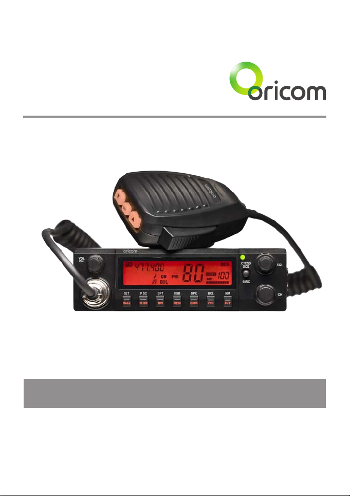
Oricom UHF058 80 Channel UHF CB Radio
Keep this user guide for future reference. Always retain your
proof of purchase in case of warranty service and register your
product on line at: AUSTRALIA: www.oricom.com.au
Page 2

Why has the ACMA increased the number of available UHF CB channels?
To provide additional channel capacity within the UHF CB Band the ACMA will over the next 5 years change the
majority of the current wideband 40 channel use to narrowband 80 channel use.
During this time wideband channel use will be gradually phased out as users upgrade their existing radio’s.
This means that the new Oricom narrowband radio you have purchased will have more channels than older
wideband radios. Some of these channels are locked and cannot be used, (see the attached channel chart for more
information).
When will this take place?
Early in 2011 new AS/NZS Standards came into effect allowing operators to use additional narrowband channels
and also use narrowband transmissions on some current wideband channels. This increased the number of
channels up to 80, 75 of which are useable voice channels.
What issues may users experience during the transition phase?
When a new narrowband radio receives a transmission from an older wideband radio the speech may sound loud
and distorted – simply adjust your radio volume for the best listening performance. When an older wideband radio
receives a signal from a new narrowband radio the speech may sound quieter - simply adjust your radio volume
for best listening performance. When operating a narrowband radio or Channel 41 - 80 interference is possible
from wideband radios transmitting on high power or on adjacent frequency.
The issues described above are not a fault of the radio but a consequence of mixed use of wideband and
narrowband radios.
It is expected that as older wideband radios are removed from service that this issue will be resolved. Most radios
in use will be narrowband eliminating this issue.
This information is current at time of printing. For further up to date information please visit www.acma.
gov.au
Oricom Connecting you now.
This unit complies with all relevant Australian
and New Zealand approval requirements
AS/NZS 4365:2011
Need Help?
If you need assistance setting up or using your Oricom product now or in the future, call Oricom Support.
Australia 1300 889 785
www.oricom.com.au
Mon-Fri 8am – 6pm AEST
New Zealand 0800 67 42 66
www.oricom.co.nz
Mon-Fri 10am – 8pm NZST
Page 3

Table of contents
Important Information 4
Please read before installing or operating Your Oricom Radio 4
Safety Information and Warnings 4
Controls and Connectors 5
Installation of your Oricom UHF 058 7
Box Contents 7
Antenna Installation 8
DC Power 8
Optional External Speaker 8
Operation 9
Dual Function buttons 9
Power ON / OFF 9
Squelch 9
To Select a Channel 9
To Select A CTCSS / DCS or 60Rx Receive channels 9
Transmitting 10
Busy Channel Lock (BCL) 10
To Transmit 10
Call Tone 11
CTCSS (Continuous Tone Coded Squelch System) 11
DCS (Digitally Coded Squelch) 11
Receive & Transmit Indicator 12
Time Out Timer (ToT) 12
Duplex Operation 12
Roger Beep (RGB) 14
Emergency Channel (EMG) 14
Priority Channel (PRI) 15
BEEP Tone (BPT) 15
Memory Scan 15
Priority Scan 16
LCD Display Controls 16
60 Rx channels 17
Factory Reset 17
UHF channels and frequencies 18
UHF058 Technical Specication 22
Customer Support 24
Warranty 25
3
Page 4

Important information
Please read before installing or operating Your
Oricom Radio
The operation of your UHF radio in Australia and New Zealand is subject to
conditions in the following licenses:
In Australia the ACMA Radio communications (Citizen Band Radio Stations)
and in New Zealand by MED the General User Radio License for Citizen
Band Radio.
Safety Information and Warnings
Potentially Explosive Atmospheres
WARNING
Turn your radio OFF when in any area with a potentially explosive
atmosphere. Sparks in such areas could cause an explosion or
re resulting in injury or even death.
NOTE: Areas with potentially explosive atmospheres are often,
but not always clearly marked. They include fueling areas such
as below deck on boats; fuel or chemical transfer or storage
facilities; areas where the air contains chemicals or particles,
such as grain, dust, or metal powders; and any other area where
you would normally be advised to turn off your vehicle engine.
Blasting Caps and Areas
To avoid possible interference with blasting operations, turn your
radio OFF near electrical blasting caps or in a “blasting area” or
in areas posted: “Turn off two way radios.” Obey all signs and
instructions.
Electromagnetic Interference/Compatibility
Nearly every electronic device is susceptible to electromagnetic
interference (EMI). To avoid the possibility of electromagnetic
interference and/or compatibility conicts, turn off your radio in
any location where posted notices instruct you to do so such as
health care facilities.
4
Page 5
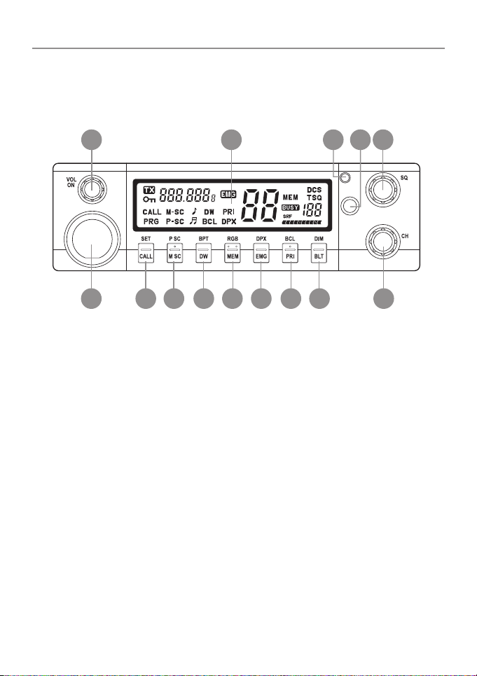
Controls and Connectors
Front View
Operation
1 2 4
1. Rotary On / Off Switch and Volume Control
2. LCD Display
3. Rx / Tx Indicator
4. CTCSS / DCS, 60 Channel Rx Selector switch
5. Rotary squelch control
6. Microphone connector
7. Call- Call Button, Set- Set Button
8. M SC – Memory Scan, P SC – Priority Scan
9. DW – Dual Watch, BPT – Beep Tone
10. MEM – Memory Skip, RGB – Roger Beep
11. EMG – Emergency Channel, DPX – Duplex
12. PRI – Primary, BCL – Busy Channel Lock
13. BLT – Back light, DIM – DIM
14. Rotary Channel Button
CTCSS
DCS
60RX
53
14131211109876
5
Page 6
Operation
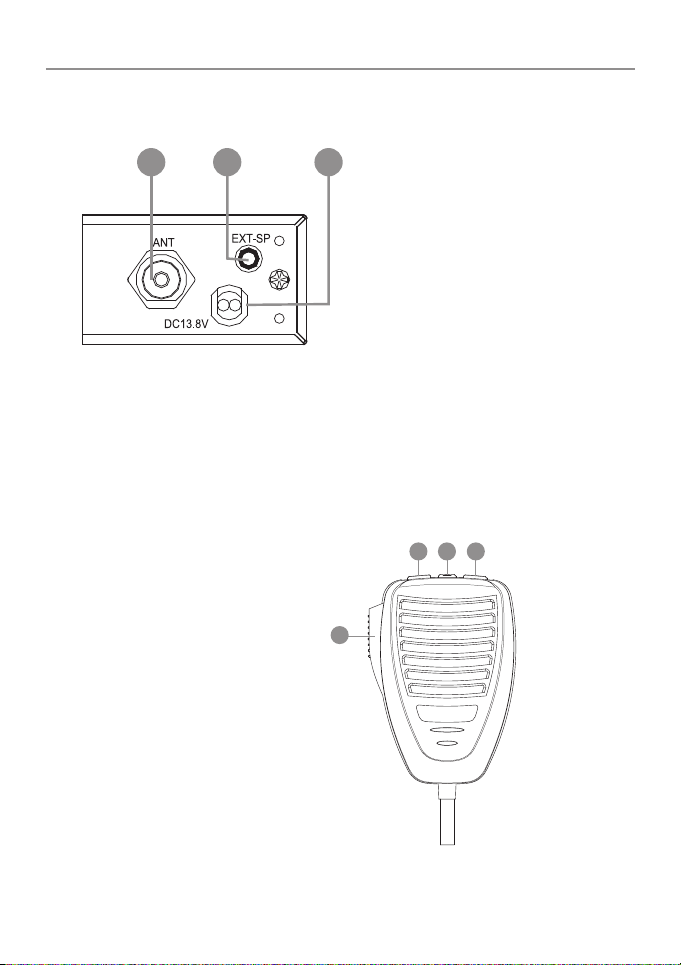
Rear View
1 2 3
1. Antenna Connection
2. 3.5mm external jack for optional 8 ohm speaker
3. Power Supply Connection
Microphone
1. Push to talk switch (PTT)
2. Select Up
3. Select Down
4. Instant Channel
6
2 4 3
1
Page 7

Installation of your Oricom UHF058
Box Contents
1 X UHF058 CB Radio
1 X Microphone
1 X DC Power cord with inline fuse
1 X Mounting bracket with mounting screws
1 X Microphone hanger
1 X User Guide
When installing your radio in your vehicle, check that during
installation you do not damage any wiring or vehicle components
that may be hidden around the mounting position.
For optimum performance your radio needs to be installed
correctly. If you are unsure about how to install your radio, we
suggest you have your radio professionally installed by a UHF
specialist or Auto electrician. When installing the radio, avoid
mounting it close to heaters or air conditioners. Never press the
PTT or CALL button before connecting the antenna to the radio.
Wiring Methods
There are two possible wiring congurations for connecting to the
Vehicles power supply.
A. Radio stays ON when the ignition is switched OFF
Connect the radio’s negative (black) lead to the vehicle chassis, or directly
to the batteries negative terminal.
Connect the radio’s positive (red) lead via the 2 Amp fuse to the battery’s
positive terminal. Alternatively, the positive lead could be connected at the
fuse box at a point that has +13.8 Volts continuously available (preferably
the battery side of the ignition switch) via the 2 Amp fuse.
B. Radio turns OFF with the ignition switch
Connect the radio’s negative (black) lead to the vehicle’s chassis, or
directly to the batteries negative terminal.
7
Page 8

Installation of your Oricom UHF058
The radio’s positive (red) lead should connect to an accessory point in the
vehicle’s fuse box via the 2 Amp fuse.
Antenna information
The antenna (not supplied) is of critical importance, to maximize your
output power and receiver senstivity.
A poorly installed, inferior quality antenna or one not designed for the
correct frequency band will give poor performance. You should only
purchase an antenna designed for the 477MHz frequency band.
Antenna installation
1. Connect the antenna to the rear antenna socket using a PL259 coaxial
connector (not supplied).
2. To obtain maximum performance from the radio, select a high quality
antenna and mount it in a good location. Never press the PTT or CALL
button before connecting the antenna to the radio.
Optional accessories
If required you may install an external (8 ohm, max 5w power) speaker
tted with a 3.5mm plug (not supplied).
DC Power
The UHF058 is designed for 13.8V DC negative earth installations only.
1. Connect the negative (Black) DC power lead to the vehicle chassis or
directly to the vehicle battery negative terminal if preferred.
2. Connect the positive (Red) DC power lead via the in line fuse to a
suitable point in the vehicle fuse box or directly to the positive battery
terminal. When selecting a suitable point take into consideration if you
want your UHF 058 to be operational when the car ignition is off.
Optional External Speaker
Depending on the installation it may be necessary to use an external
speaker (not supplied) to give improved volume and clarity. This can be
plugged into the EXT –SPK socket on the rear of the unit.
8
Page 9

Operation
Operation
Dual Function buttons
The dual function button (buttons 7 to 13) have two functions.
To use the primary function (printed on the button) just press the button. To
use the secondary function (printed above the button)
press and hold the button for 2 seconds.
Power ON / OFF
Rotate the power switch in a clockwise direction to turn the unit ON,
adjust the volume to a comfortable level. Rotate the Power Switch counter
clockwise until it click to turn off the power.
Squelch
To adjust the level of squelch use the rotary SQL control. Turning the control
clockwise reduces the amount of squelch, turning counter clockwise
increase the amount of squelch. To reduce the signals that you can hear,
increase the squelch, to hear more signals which may include weak signals
decrease the squelch.
To Select a Channel
To select a channel rotate the CH control clockwise or counter clockwise to
the desired channel.
To Select A CTCSS / DCS or 60Rx Receive channels
Press the CTCSS / DCS button once to obtain CTCSS channel select. Press
twice to obtain DCS channel select.
Press and hold the button for 2 seconds to obtain the 60Rx channels.
9
Page 10

Operation
Transmitting
NOTE: Before transmitting on any channel, listen to check the channel
is not already in use.
Busy Channel Lock (BCL)
If you turn ON the BCL feature of the UHF058 you will be prevented from
accidentally transmitting while the channel is in use.
To Turn ON BCL
1. Press and hold the BCL button for 2 seconds, BCL will appear on the
LCD display.
To Turn OFF BCL
1. Press and hold the BCL button for 2 seconds, BCL will disappear from
the LCD display.
To Transmit
1. Select the channel you wish to use, please refer the Channel Reference
at the end of this user guide for a list of available channels and their use.
2. Press the PTT switch on the Mic
TIP: To ensure your voice is transmitted with the best clarity hold the
microphone 5 to 7 cm from your mouth, talk at a normal level, do not
shout.
10
Page 11

Operation
Call Tone
A call tone alerts others on your channel that you want to talk.
Your radio has 5 call tones to choose from.
To select a call tone
1. Press and hold SET for 2 seconds.
2. Rotate the Channel button ( or press the Up / Down Select on the Mic)
to select the desired Call Tone.
To transmit a call tone
1. Pressing the call switch will cause a 3 second call tone to be
transmitted.
NOTE: Australian and New Zealand standards restrict tone calling to 3
seconds in any 60 second period.
CTCSS (Continuous Tone Coded Squelch System)
Your UHF058 has 38 CTCSS codes to minimise interference from other
users. You will only hear transmissions from users using the same code.
To select a CTCSS code
1. Press the CTCSS / DCS button, TSQ of will blink on the
LCD display.
2. Turn the Channel control to select the desired CTCSS code.
3. Press the CTCSS / DCS button twice to return to standby.
DCS (Digitally Coded Squelch)
Your UHF058 provides for 104 DCS codes. These are digitally coded squelch
codes which provide additional privacy.
11
Page 12

Operation
To select a DCS code
1. Press the CTCSS / DCS button twice, DCS – of appears on the
LCD display.
2. Rotate the Channel button or press Up / Down Select on the Mic to
select the desired DCS channel code.
3. Press the CTCSS / DCS button once to return to standby.
Receive & Transmit Indicator
The LED indictor will illuminate green when the unit is receiving a signal,
when transmitting it will illuminate red. When in standby the LED is out.
Time Out Timer (ToT)
Australian and New Zealand standards require that if the PTT is pressed for
more than 3 minutes the unit must stop transmitting. The UHF058 is set to
stop transmitting after 2 minutes and 30 seconds of continous transmitting.
After that time the unit will stop transmitting and TOT will appear in the
display to indicate that the ToT has activated.
Duplex Operation
General
Your radio has a Repeater Access function to allow use of local Repeater stations
(if available in your area). Repeaters are shared radio system installed by
interested parties (clubs, local business etc.) that pick transmissions on specic
channels and re-transmit (or repeat) the received signal to another channel.
12
Channel 2
Channel 32
Repeater Station
C
h
a
Channel 32
n
n
e
l 2
Page 13

Operation
The Repeater Access function can be set (from channel 1 to 8 and 41 to 48)
used by local repeater stations. When activated, your radio will receive the
Repeater on its specic channel (all repeater outputs are on channel 1 to 8
and 41 to 48) but transmits to the repeater channel 31 through to 38 and 71
through to 78.
e.g.
CH01 on Duplex mode will receive on CH01 but transmit on CH31
CH02 on Duplex mode will receive on CH01 but transmit on CH32.
CH and Number
1 476.425 477.175 CH31
2 476.450 477.200 CH32
3 476.475 477.225 CH33
4 476.500 477.250 CH34
5 476.525 477.275 CH35
6 476.550 477.300 CH36
7 476.575 477.325 CH37
8 476.600 477.350 CH38
41 476.4375 477.1875 CH71
42 476.4625 477.2125 CH72
43 476.4875 477.2375 CH73
44 476.5125 477.2625 CH74
45 467.5375 477.2875 CH75
46 476.5625 477.3125 CH76
47 476.5875 477.3375 CH77
48 476.6125 477.3625 CH78
Simplex mode Transmit/
reciever Frequency (MHz)
Duplex Mode transmit
Frequency(MHz)
13
Page 14

Operation
To Turn Duplex (DPX) ON
1. Press and hold the DPX button for 2 seconds, DPX will appear on the
LCD display.
To Turn Duplex (DPX) OFF
1. Press and hold the DPX button for 2 seconds, the DPX will disappear
from the LCD display.
NOTE: For an up to date list of repeaters you can visit:
http://www.acma.gov.au
Roger Beep (RGB)
Roger beep emits a tone when you release the PTT switch.
To turn ON the roger beep
1. Press the RGB button for 2 seconds, the <note icon> appears in
the display.
To turn OFF the roger beep
1. Press the RGB button for 2 seconds, the <note icon> disappears from
the display.
Emergency Channel (EMG)
The EMG button gives instant access to emergency channels 5 and 35.
To access the emergency channel
1. Press the EMG button, Channel 5 I selected and displayed on the LCD.
2. If you press the EMG button a 2nd time the channel changes to 35.
3. If you pres the EMG button a 3rd time the unit return to the original
channel.
14
Page 15

Operation
Priority Channel (PRI)
You can select a priority channel which is used during scanning functions
and can be accessed immediately via the INS button on the Microphone.
To Select the Primary Channel
1. Select the desired primary channel using the channel control, including
any CTCSS or DCS code.
2. Press the PRI button on the unit or press and hold the INS button on the
Microphone.
To switch to the primary Channel
1. Press the INS button on the Microphone.
BEEP Tone (BPT)
The Beep Tone emits a tone when you press any of the buttons on the
Microphone (except the PTT switch)
To Turn ON the BEEP Tone
1. Press and hold the BPT button for 2 seconds, BPT appears on the LCD
display.
To Turn OFF the BEEP Tone
1. Press and hold the BPT button for 2 seconds, the BPT disappears from
the LCD display.
Memory Scan
Initially All 80 channels are stored in memory, indicated by MEM next to the
channel on the LCD display. During a memory scan all channels in memory
are scanned for a signal.
15
Page 16

Operation
To Remove or Add a channel to the memory
1. Select the channel you wish to add or remove from memory.
2. Press the MEM key to add or remove from memory, MEM will be
displayed on the LCD if the channel is in memory.
To start a Memory Scan
1. Press the M SC button, the scan will start, M-SC will be displayed on
the LCD display.
To stop a Memory Scan
1. Press the M SC button, the scan will stop, M-SC will disappear from
the LCD display.
Priority Scan
In a priority scan the selected priority channel is checked for every 5
memory channels.
To Start a Priority Scan
1. Press the P SC button for 2 seconds, the priority scan will start,
P-SC will be displayed on the LCD.
To Stop a Priority Scan
1. Press the P SC button for 2 seconds, the Priority Scan will stop, P-SC
will disappear from the LCD display.
LCD Display Controls
Display Backlight
You can select from two colour options for the LCD backlight. The two
options are Orange and Green.
16
Page 17

Operation
To select the backlight colour (BLT)
1. Press the BLT button, the display will toggle between Orange and Green.
Display Brightness
You can reduce the brightness of the LCD backlight to be more comfortable
while driving at night.
To Dim the display
1. Press and hold the DIM button for 2 seconds, the display will toggle
between normal and DIM brightness levels.
60 Rx channels
The UHF058 has 60 receive only channels which can be programmed from
450MHz to 512MHz in steps of 12.5KHz.
To program a receive channel.
1. Press and hold the 60Rx button for 2 seconds, the display will show
channel 41. to select a different channel use the Channel control.
2. Press the PRI button, the 450 in the frequency display will start
blinking, use the Channel control to select the desired MHz.
3. Press the PRI button, the 000 in the frequency display will start
blinking, use the Channel control to select the desired KHz.
4. Press MEM, the frequency is stored to that channel.
Factory Reset
Should it be necessary you can return all the UHF058 settings to the factory
defaults to do this.
1. Switch the unit OFF.
2. Press and hold the CALL button.
3. While still holding the Call button, turn the power switch to ON, this will
reset the factory defaults.
17
Page 18

UHF channels and frequencies
Channel Frequency Table
Radiocommunications (Citizen Band Radio Stations) Class
Licence 2002
No licence is required to own or operate this radio in Australia and New
Zealand. The Radiocommunications (Citizen Band Radio Stations) Class
Licence 2002 contains the technical parameters, operating requirements,
conditions of licence and relevant standards for Citizen Band (CB) radios. CB
radios must comply with the class licence for their use to be authorised under
the class licence.
UHF channels and frequencies
IMPORTANT NOTE: The operation of your UHF radio in Australia and New
Zealand is subject to conditions in the following licenses:
In Australia the ACMA Radio communications (Citizen Band Radio Stations)
and in New Zealand by MED the General User Radio License for Citizen Band
Radio.
18
Page 19

UHF channels and frequencies
EMC Technologies (NZ) Ltd
Test Report No 101127.1
Report date: 25
th
November 2010
6.2 Nominal Carrier
Table 1 Nominal Carrier Frequency
Tx Rx
Channel
01* 476.4250 476.4250 21 476.9250 476.9250
02* 476.4500 476.4500 22† 476.9500 476.9500
03* 476.4750 476.4750 23† 476.9750 476.9750
04* 476.5000 476.5000 24 477.0000 477.0000
05* 476.5250 476.5250 25 477.0250 477.0250
06* 476.5500 476.5500 26 477.0500 477.0500
07* 476.5750 476.5750 27 477.0750 477.0750
08* 476.6000 476.6000 28 477.1000 477.1000
9 476.6250 476.6250 29 477.1250 477.1250
10 476.6500 476.6500 30 477.1500 477.1500
11 476.6750 476.6750 31* 477.1750 477.1750
12 476.7000 476.7000 32* 477.2000 477.2000
13 476.7250 476.7250 33* 477.2250 477.2250
14 476.7500 476.7500 34* 477.2500 477.2500
15 476.7750 476.7750 35* 477.2750 477.2750
16 476.8000 476.8000 36* 477.3000 477.3000
17 476.8250 476.8250 37* 477.3250 477.3250
18 476.8500 476.8500 38* 477.3500 477.3500
19 476.8750 476.8750 39 477.3750 477.3750
20 476.9000 476.9000 40 477.4000 477.4000
41* - 476.4375 61‡ — —
42* - 476.4625 62‡ — —
43* - 476.4875 63‡ — —
44* - 476.5125 64 477.0125 477.0125
45* - 476.5375 65 477.0375 477.0375
46* - 476.5625 66 477.0625 477.0625
47* - 476.5875 67 477.0875 477.0875
48* - 476.6125 68 477.1125 477.1125
49 476.6375 476.6375 69 477.1375 477.1375
50 476.6625 476.6625 70 477.1625 477.1625
51 476.6875 476.6875 71* 477.1875 -
52 476.7125 476.7125 72* 477.2125 -
53 476.7375 476.7375 73* 477.2375 -
54 476.7625 476.7625 74* 477.2625 -
55 476.7875 476.7875 75* 477.2875 -
56 476.8125 476.8125 76* 477.3125 -
57 476.8375 476.8375 77* 477.3375 -
58 476.8625 476.8625 78* 477.3625 -
59 476.8875 476.8875 79 477.3875 477.3875
60 476.9125 476.9125 80 477.4125 477.4125
Freq Freq Freq Freq
MHZ MHz MHz MHz
Channel
Tx Rx
19
Page 20

UHF channels and frequencies
* The primary use for these channels is repeater operation using 750 kHz offset.
Channels 1-8 and 41-48 inclusive are used for mobile reception and channels 31-38
and 71-78 for mobile transmission. In addition, any designated repeater channel may
be used for simplex operation in areas where it is not used for repeater operation.
† Speech telephony shall be inhibited on these channels.
‡ At the time of production Channels 61, 62 and 63 are guard channels and are not
available for use.
Channel 5 and 35 (paired for Duplex repeaters) are reserved as emergency
channels and should be used only in an emergency.
CTCSS and DCS will not operate on Channel 5 and 35.
A list of currently authorised channels can be obtained from the ACMA website
in Australia and the MED website in New Zealand. Channel 11 is a calling
channel generally used to call others and channel 40 is the customary road
vehicle channel.
Once contact is established on the calling channel, both stations should
move to another unused "SIMPLEX" channel to allow others to use the calling
channel.
Channels 22 and 23 are for Telemetry and Telecommand use, voice
communications are not allowed on these channels.
Channel 9 and above are the best choices for general use in Simplex mode.
20
Page 21

UHF channels and frequencies
38 CTCSS CODE LIST
CODE Frequency(Hz) CODE Frequency(Hz)
OFF OFF 20 131.8
1 67.0 21 136.5
2 71.9 22 141.3
3 74.4 23 146.2
4 77.0 24 151.4
5 79.7 25 156.7
6 82.5 26 162.2
7 85.4 27 167.9
8 88.5 28 173.8
9 91.5 29 179.9
10 94.8 30 186.2
11 97.4 31 192.8
12 100.0 32 203.5
13 103.5 33 210.7
14 107.2 34 218.1
15 110.9 35 225.7
16 114.8 36 233.6
17 118.8 37 241.8
18 123.0 38 250.3
19 127.3
21
Page 22

UHF058 Technical Specication
UHF058 Technical Specication
Compliance AS/NZS 4365:2011
Frequency Range TX 476.425 - 477.4125MHz
Frequency Range RX 400 - 512MHz
Number of TX/RX Channels 75 UHF CB
Number user programmable of RX Only
Channels
Channel Spacing TX/RX 12.5KHz
Operating modes Simplex, Repeater TX offset (+750kHz)
Wideband scanner bands 450-512mHz
Selcall ID 5 digit with Alpha display
Scanning Speed 250 ms per channel
Antenna Impeadance 50 Ohms
Operating Volts Nominal 13.8 VDC
Operating Volts Range 10 - 15 VDC
Over Voltage Protection voltage regulator
Over Current Protection 2 Amp fuse
Reverse Polarity Protection Series Diode
Frequency Stability +/- 5ppm
Transmitter
RF Power Output Nominal 5.0 Watts
Modulation F3E (FM)
Maximum Deviation 2.5kHz
Spurious Emissions < -30dBm
TX Audio pre-emphasis +6dB per octave 300Hz to 3kHz
Audio Signal to Noise Ratio > 35dB
Current Consumption during TX 1.6 Amps with 50 Ohm antenna termination
60
22
Page 23

UHF058 Technical Specication
Reciever
Circuit Type Dual conversion superheterodyne
IF Frequencies 1st IF = 30.85MHz, 2nd IF = 450kHz
Current Consumption during RX 170mA
Sensitivity < -123dBm for 12dB SINAD
Sensitivity Receive only channels < -110dBM for 12dB SINAD
Selectivity +/-3.75kHz min @ 3dB to +/-15kHz max @
Intermodulation Immunity > 70dB
Spurious Immunity > 70dB
Audio Output Power 3 Watts Maximum
RX Audio Signal de-emphasis -6dB per octave 300Hz to 3 kHz
Audio frequency response 300Hz to 3kHz
Dimensions Transceiver 135 (d) x 140 (w) x 40 (h)
Weight approx 670g
40dB
23
Page 24

Customer Support
Customer Support
If you have any problems setting up or using this product you will find useful
tips and information in the Troubleshooting section of this user guide as well as
“Frequently Asked Questions” on our website www.oricom.com.au.
If you have further questions about using the product after reviewing the resources
above or would like to purchase replacement parts or accessories please call our
Customer Support Team. Our dedicated local support team are more likely to be
able to help you than the retailer where you made your purchase.
Important
Please retain your purchase receipt and attach to the back page of this user guide
as you will need to produce this if warranty service is required. Take a few moments
to register your product online: www.oricom.com.au
24
Page 25

Warranty
How to make a claim under Warranty in Australia
Oricom has a simple warranty process for you to follow:
• PleasecalloremailourCustomerSupportTeam,contactdetailsfollow.
• ACustomerSupportTeammemberwillverifyaftertroubleshootingwithyouif
your product qualies under warranty. If so, they will give you a Product Return
Authorisation number.
• Wewillthen email or faxaReturnAuthorisation formandaRepairNotice (if
necessary), together with instructions on how to return the goods for warranty
service.
Please note that if a Customer Support Team member advises that your product
does not qualify for return, this warranty does not apply to your product.
Products that are authorised to be returned to Oricom in Australia must include all
of the following:
• AcompletedReturnAuthorisationform
• AcopyofyourProofofPurchase(pleasekeepyouroriginalcopy)
• Thefaultyproduct,includingallaccessories.
Send the approved returns to:
Oricom International Pty Ltd
Locked Bag 658
South Windsor NSW 2756 Australia
Please note that this warranty excludes expenses incurred by you in returning any
faulty product to us. You must arrange and pay any expenses incurred (including
postage, delivery, freight, transportation or insurance of the product) to return the
faulty product to us, however, we will arrange delivery of the repaired or replaced
faulty product to you.
Important Information
Repair Notice
Please be aware that the repair of your goods may result in the loss of any usergenerated data (such as stored telephone numbers, text messages and contact
information). Please ensure that you have made a copy of any data saved on your
goods before sending for repair.
Please also be aware that goods presented for repair may be replaced by
refurbished goods or parts of the same type rather than being repaired.
25
Page 26

Warranty
Warranty Information (Australia)
This Warranty is provided by Oricom International Pty Ltd ABN 46 086 116 369,
Unit 1, 4 Sovereign Place, South Windsor NSW 2756, herein after referred to as
“Oricom”.
Oricom makes no other warranties or conditions, express or implied, including as
to acceptable quality and tness for a particular purpose, except as stated in this
Warranty.
Any implied warranties that may be imposed by law are limited in duration to the
Warranty Period.
Oricom warrants that the product is free from defects in materials or workmanship
during the Warranty Period. This Warranty does not extend to any product from
which the serial number has been removed or was purchased outside of Australia.
This warranty in no way affects your statutory warranty rights under the Competition
and Consumer Act 2010 or any other similar legislation.
The Warranty Period will be 3 years from the date of purchase of the product
evidenced by your dated sales receipt. You are required to provide proof of
purchase as a condition of receiving warranty services.
You are entitled to a replacement product or repair of the product according to the
terms and conditions of this document if your product is found to be faulty within
the Warranty Period. This Warranty extends to the original purchaser only and is not
transferable.
Rechargeable battery cells and rechargeable battery packs (if supplied) with this
product are covered under this warranty for a period of 90 days.
Products distributed by Oricom are manufactured using new materials or new and
used materials equivalent to new in performance and reliability. Spare parts may
be new or equivalent to new. Spare parts are warranted to be free from defects in
material or workmanship for thirty (30) days or for the remainder of the Warranty
Period of the Oricom branded product in which they are installed, whichever is
longer. During the Warranty Period, Oricom will where possible repair and if not
26
Page 27

Warranty
replace the faulty product or part thereof. All component parts removed under
this Warranty become the property of Oricom. In the unlikely event that your
Oricom product has a recurring failure, Oricom may, subject to the Competition
and Consumer Act 2010, at its discretion, elect to provide you with a replacement
product of its choosing that is at least equivalent to your product in performance.
Oricom does not warrant that the operation of the product will be uninterrupted or
error free.
Oricom is not responsible for damage that occurs as a result of your failure to
follow the instructions that came with the product. These terms and conditions
together with any specic terms and conditions contained in the user guide to the
product purchased constitute the complete and exclusive agreement between you
and Oricom regarding the product.
No change to the conditions of this Warranty is valid unless it is made in writing
and signed by an authorised representative of Oricom.
Oricom will not be in breach of a warranty expressly set out in this User Guide
or under the Competition and Consumer Act 2010 and excludes any liability for
damages or any other remedy arising under any other legislation or the common
law if the damage occurs as a result of:
1. failure by you to adhere to the warnings and follow the instructions set out in
this user guide for the proper installation and use of the product;
2. negligence on your part or misuse by you of the product;
3. an uncontrollable external cause which results in the product not functioning
including but not limited to power failure, lightning or over voltage; and
4. modification to the product or services carried out on the product by anyone
other than Oricom or Oricom’s authorised service provider.
Oricom will not be liable for any damages caused by the product or the failure of
the product to perform, including any lost prots or savings or special, incidental
or consequential damages. Oricom is not liable for any claim made by a third
party or made by you on behalf of a third party. This limitation of liability applies
27
Page 28

Warranty
whether damages are sought, or a claim made, under this Warranty or as a tort
claim (including negligence and strict product liability), a contract claim or any other
claim. However, this limitation of liability will not apply to claims for personal injury.
Nothing in this Warranty excludes, restricts or modifies any condition, warranty,
right or remedy which pursuant to the Competition and Consumer Act 2010
applies to this Warranty and which may not be so excluded, restricted or modied.
For warranties that cannot be excluded, restricted or modied, Oricom limits the
remedies available to those specied in the relevant legislation.
Oricom products come with guarantees that cannot be excluded under the
Australian Consumer Law. You are entitled to a replacement or refund for a major
failure and compensation for any other reasonably foreseeable loss or damage. You
are also entitled to have the goods repaired or replaced if the goods fail to be of
acceptable quality and the failure does not amount to a major failure.
28
Page 29

Page 30

Contact details for Oricom support and warranty claims in Australia
Oricom International Pty Ltd
Locked Bag 658
South Windsor, NSW 2756
Australia
Email: support@oricom.com.au
Phone: 1300 889 785
(Monday to Friday 8am to 6pm AEST)
Web: www.oricom.com.au
Fax: (02) 4574 8898
Contact details for Oricom support and warranty claims in New Zealand
Email: support@oricom.co.nz
Phone: 0800 674 266
(Monday to Friday 10am to 8pm NZST)
Web: www.oricom.co.nz
Ref: 25102011
 Loading...