


UHF058
User Guide
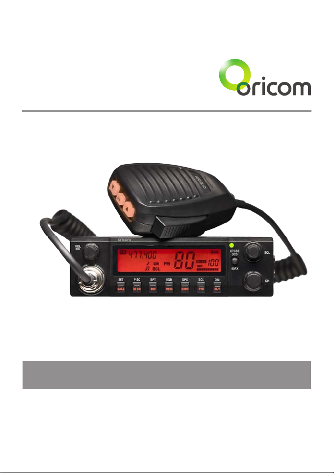
Oricom UHF058 80 Channel UHF CB Radio
Keep this user guide for future reference. Always retain your
proof of purchase in case of warranty service and register your
product on line at: AUSTRALIA: www.oricom.com.au
Need Help?
If you need assistance setting up or using your Oricom product now or in the future, call Oricom Support.
Australia 1300 889 785
www.oricom.com.au
Mon-Fri 8am – 6pm AEST
New Zealand 0800 67 42 66
www.oricom.co.nz
Mon-Fri 10am – 8pm NZST
This unit complies with all relevant Australian
and New Zealand approval requirements
AS/NZS 4365:2011
Why has the ACMA increased the number of available UHF CB channels?
To provide additional channel capacity within the UHF CB Band the ACMA will over the next 5 years change the
majority of the current wideband 40 channel use to narrowband 80 channel use.
During this time wideband channel use will be gradually phased out as users upgrade their existing radio’s.
This means that the new Oricom narrowband radio you have purchased will have more channels than older
wideband radios. Some of these channels are locked and cannot be used, (see the attached channel chart for more
information).
When will this take place?
Early in 2011 new AS/NZS Standards came into effect allowing operators to use additional narrowband channels
and also use narrowband transmissions on some current wideband channels. This increased the number of
channels up to 80, 75 of which are useable voice channels.
What issues may users experience during the transition phase?
When a new narrowband radio receives a transmission from an older wideband radio the speech may sound loud
and distorted – simply adjust your radio volume for the best listening performance. When an older wideband radio
receives a signal from a new narrowband radio the speech may sound quieter - simply adjust your radio volume
for best listening performance. When operating a narrowband radio or Channel 41 - 80 interference is possible
from wideband radios transmitting on high power or on adjacent frequency.
The issues described above are not a fault of the radio but a consequence of mixed use of wideband and
narrowband radios.
It is expected that as older wideband radios are removed from service that this issue will be resolved. Most radios
in use will be narrowband eliminating this issue.
This information is current at time of printing. For further up to date information please visit www.acma.
gov.au
Oricom Connecting you now.

3
Table of contents
Important Information 4
Please read before installing or operating Your Oricom Radio 4
Safety Information and Warnings 4
Controls and Connectors 5
Installation of your Oricom UHF 058 7
Box Contents 7
Antenna Installation 8
DC Power 8
Optional External Speaker 8
Operation 9
Dual Function buttons 9
Power ON / OFF 9
Squelch 9
To Select a Channel 9
To Select A CTCSS / DCS or 60Rx Receive channels 9
Transmitting 10
Busy Channel Lock (BCL) 10
To Transmit 10
Call Tone 11
CTCSS (Continuous Tone Coded Squelch System) 11
DCS (Digitally Coded Squelch) 11
Receive & Transmit Indicator 12
Time Out Timer (ToT) 12
Duplex Operation 12
Roger Beep (RGB) 14
Emergency Channel (EMG) 14
Priority Channel (PRI) 15
BEEP Tone (BPT) 15
Memory Scan 15
Priority Scan 16
LCD Display Controls 16
60 Rx channels 17
Factory Reset 17
UHF channels and frequencies 18
UHF058 Technical Specication 22
Customer Support 24
Warranty 25
4
Important information
Please read before installing or operating Your
Oricom Radio
The operation of your UHF radio in Australia and New Zealand is subject to
conditions in the following licenses:
In Australia the ACMA Radio communications (Citizen Band Radio Stations)
and in New Zealand by MED the General User Radio License for Citizen
Band Radio.
Safety Information and Warnings
Potentially Explosive Atmospheres
Turn your radio OFF when in any area with a potentially explosive
atmosphere. Sparks in such areas could cause an explosion or
re resulting in injury or even death.
NOTE: Areas with potentially explosive atmospheres are often,
but not always clearly marked. They include fueling areas such
as below deck on boats; fuel or chemical transfer or storage
facilities; areas where the air contains chemicals or particles,
such as grain, dust, or metal powders; and any other area where
you would normally be advised to turn off your vehicle engine.
Blasting Caps and Areas
To avoid possible interference with blasting operations, turn your
radio OFF near electrical blasting caps or in a “blasting area” or
in areas posted: “Turn off two way radios.” Obey all signs and
instructions.
Electromagnetic Interference/Compatibility
Nearly every electronic device is susceptible to electromagnetic
interference (EMI). To avoid the possibility of electromagnetic
interference and/or compatibility conicts, turn off your radio in
any location where posted notices instruct you to do so such as
health care facilities.
WARNING
Operation
5
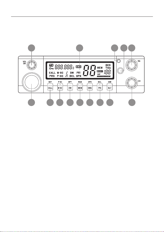
Controls and Connectors
Front View
60RX
CTCSS
DCS
1 2 4
14131211109876
53
1. Rotary On / Off Switch and Volume Control
2. LCD Display
3. Rx / Tx Indicator
4. CTCSS / DCS, 60 Channel Rx Selector switch
5. Rotary squelch control
6. Microphone connector
7. Call- Call Button, Set- Set Button
8. M SC – Memory Scan, P SC – Priority Scan
9. DW – Dual Watch, BPT – Beep Tone
10. MEM – Memory Skip, RGB – Roger Beep
11. EMG – Emergency Channel, DPX – Duplex
12. PRI – Primary, BCL – Busy Channel Lock
13. BLT – Back light, DIM – DIM
14. Rotary Channel Button
Operation
6
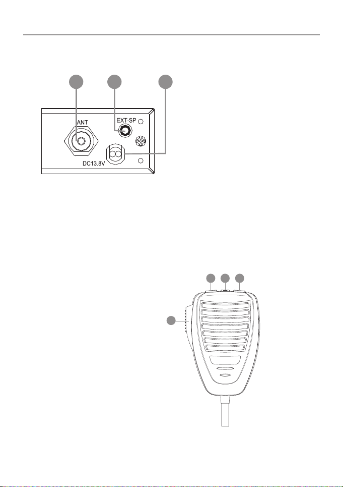
Rear View
1 2 3
1. Antenna Connection
2. 3.5mm external jack for optional 8 ohm speaker
3. Power Supply Connection
Microphone
1. Push to talk switch (PTT)
2. Select Up
3. Select Down
4. Instant Channel
1
2 4 3
7
Installation of your Oricom UHF058
Box Contents
1 X UHF058 CB Radio
1 X Microphone
1 X DC Power cord with inline fuse
1 X Mounting bracket with mounting screws
1 X Microphone hanger
1 X User Guide
When installing your radio in your vehicle, check that during
installation you do not damage any wiring or vehicle components
that may be hidden around the mounting position.
For optimum performance your radio needs to be installed
correctly. If you are unsure about how to install your radio, we
suggest you have your radio professionally installed by a UHF
specialist or Auto electrician. When installing the radio, avoid
mounting it close to heaters or air conditioners. Never press the
PTT or CALL button before connecting the antenna to the radio.
Wiring Methods
There are two possible wiring congurations for connecting to the
Vehicles power supply.
A. Radio stays ON when the ignition is switched OFF
Connect the radio’s negative (black) lead to the vehicle chassis, or directly
to the batteries negative terminal.
Connect the radio’s positive (red) lead via the 2 Amp fuse to the battery’s
positive terminal. Alternatively, the positive lead could be connected at the
fuse box at a point that has +13.8 Volts continuously available (preferably
the battery side of the ignition switch) via the 2 Amp fuse.
B. Radio turns OFF with the ignition switch
Connect the radio’s negative (black) lead to the vehicle’s chassis, or
directly to the batteries negative terminal.

8
Installation of your Oricom UHF058
The radio’s positive (red) lead should connect to an accessory point in the
vehicle’s fuse box via the 2 Amp fuse.
Antenna information
The antenna (not supplied) is of critical importance, to maximize your
output power and receiver senstivity.
A poorly installed, inferior quality antenna or one not designed for the
correct frequency band will give poor performance. You should only
purchase an antenna designed for the 477MHz frequency band.
Antenna installation
1. Connect the antenna to the rear antenna socket using a PL259 coaxial
connector (not supplied).
2. To obtain maximum performance from the radio, select a high quality
antenna and mount it in a good location. Never press the PTT or CALL
button before connecting the antenna to the radio.
Optional accessories
If required you may install an external (8 ohm, max 5w power) speaker
tted with a 3.5mm plug (not supplied).
DC Power
The UHF058 is designed for 13.8V DC negative earth installations only.
1. Connect the negative (Black) DC power lead to the vehicle chassis or
directly to the vehicle battery negative terminal if preferred.
2. Connect the positive (Red) DC power lead via the in line fuse to a
suitable point in the vehicle fuse box or directly to the positive battery
terminal. When selecting a suitable point take into consideration if you
want your UHF 058 to be operational when the car ignition is off.
Optional External Speaker
Depending on the installation it may be necessary to use an external
speaker (not supplied) to give improved volume and clarity. This can be
plugged into the EXT –SPK socket on the rear of the unit.

Operation
9
Operation
Dual Function buttons
The dual function button (buttons 7 to 13) have two functions.
To use the primary function (printed on the button) just press the button. To
use the secondary function (printed above the button)
press and hold the button for 2 seconds.
Power ON / OFF
Rotate the power switch in a clockwise direction to turn the unit ON,
adjust the volume to a comfortable level. Rotate the Power Switch counter
clockwise until it click to turn off the power.
Squelch
To adjust the level of squelch use the rotary SQL control. Turning the control
clockwise reduces the amount of squelch, turning counter clockwise
increase the amount of squelch. To reduce the signals that you can hear,
increase the squelch, to hear more signals which may include weak signals
decrease the squelch.
To Select a Channel
To select a channel rotate the CH control clockwise or counter clockwise to
the desired channel.
To Select A CTCSS / DCS or 60Rx Receive channels
Press the CTCSS / DCS button once to obtain CTCSS channel select. Press
twice to obtain DCS channel select.
Press and hold the button for 2 seconds to obtain the 60Rx channels.
 Loading...