

Page 1
Page 2

1 General Information
Warnings
It is very important that you read the User Guide carefully as it contains
detailed information on installation, programming and operational issues which
you will need to be aware of to ensure the Care Phone operates properly. If
you are not clear about how to install the phone or have any queries on any
issue, please contact our Australian Customer Support Service on 1300 889
785. The following is a list of some of the important issues and important
warnings which you need to be aware of. This is not a summary of all the
important issues and you must still read the User Guide in full.
The emergency call feature will not be activated in the following
circumstances:-
• the remote pendant is not within the range of up to 30 metres from the
phone;
• the battery for the remote pendant is not properly installed or is flat;
• the phone is not properly connected to power and the telephone line or the
phone battery is not properly installed or is flat;
• the phone is engaged or off the hook;
• No emergency numbers have been stored in the phones memory.
Warnings
• Add your emergency message to more than one number to avoid
circumstances where the only person contacted is not available.
• Inform the person(s) whose number(s) will be stored in the emergency
message that they need to acknowledge the call by pressing 0 at the
appropriate time.
• Ensure the numbers are stored with the area code and in the order in
which you want the phone to call them.
• Edit the stored phone numbers for persons to be contacted in emergency
situations when they change their phone numbers.
• Ensure the telephone has charged backup batteries installed at all times.
• Test the emergency call feature regularly.
• Test the batteries on both the phone and the pendant regularly to ensure
they are charged sufficiently to activate the emergency call feature.
• The telephone is designed for indoor use only. Do not install the telephone
in areas where there is the risk of an explosion, excessive exposure to
smoke, dust, vibrations, chemicals, moisture and heat.
• Do not use your telephone during an electrical thunderstorm as it is possible
to get an electric shock. Refer to information contained in Telstra White
pages directory.
2
Page 3

• The earpiece of the handset may attract small metal objects such as
staples and pins. Care should be taken when placing the handset near
these items.
• Setting the receiver volume to maximum may, under some situations
cause ear damage. We suggest returning the handset volume control to
the “0” position after each call.
• Do not install in damp locations such as a bathroom or laundry, do not
expose the unit to direct sunlight.
Notes for operation in New Zealand
The grant of a Telepermit for any item of terminal equipment indicates only
that Telecom has accepted that the item complies with the minimum conditions
for connection to its network. It indicates no endorsement of the product by
Telecom, nor does it provide any sort of warranty. Above all, it provides no
assurance that any item will work correctly in all respects with another item
of Telepermitted equipment of a different make or model, nor does it imply
that any product is compatible with all of Telecom’s network services.
This equipment shall not be set to make automatic calls to the Telecom “111”
Emergency Service.
This equipment may not provide for the effective hand-over of a call to another
device connected to the same line.
This equipment should not be used under any circumstances that may
constitute a nuisance to other Telecom Customers.
If a charge for local calls is unacceptable, the “DIAL“ button should NOT be
used for local calls. Only the 7 digits of the local number should be dialled
from your telephone. DO NOT dial the area code digit or the “0“ prefix.
REN (RN for New Zealand)
The REN (Ringer Equivalence Number) or (RN) is of significance only if you
wish to connect more than 1 telephone to your telephone line. A standard
telephone line has a maximum REN capacity of 3 (RN of 5). It is possible to
connect 3 devices with a REN of 1 (RN of 1) with no degradation to the
product’s performance. Exceeding this limit may cause the volume of the
ringer in any phone to decrease or not ring at all.
Caller ID
Customers using non Telecom toll services should not use the dial back
feature for local calls as this will incur a charge only the 7 digit number
should be dialled. Some of the CID services listed may not be available in
New Zealand.
3
Page 4
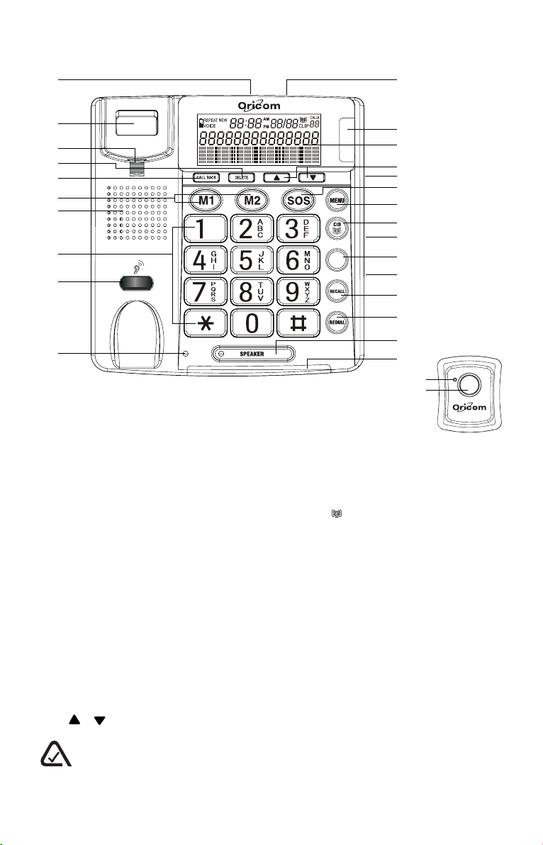
2 Location of controls
CID
1
2
3
4
5
6
7
8
9
345
10
1. Telephone Line Jack
2. Hook switch
3. Handset Holder
4. Delete Button
5. Call Back Button
6. Memory Buttons (M1, M2)
7. Speaker
8. Keypad
9. Receiver volume control
10. Receiver volume LED
11. Power Jack
12. New Call LED
13. Display
14. / Buttons
11
12
13
14
15
16
17
18
19
OK
20
21
22
23
24
25
26
27
15. Ringer Hi/Mid/Low Switch
16. SOS Button
17. Menu Button
18.
Button
19. Tone Hi/Lo Switch
20. Ok Button
21. Volume Hi/Lo Switch
22. Recall Button
23. Redial Button
24. Speaker Button With LED
25. Ringer LED
26. Remote pendant LED
27. Remote pendant Button
N13134
The A-Tick symbol indicates that this product complies with all current Australian ACMA
standards.
4
Page 5
3 Installation
3.1 Installing batteries (supplied) in the phone
Warnings
You must install 4 AA Alkaline batteries in the phone base. The battery
back up system will then be able to power the unit for up to 12 hours if
there is a mains power failure.
If your mains power has been turned off for an extended period or the
power supply to the phone has been unplugged from mains power you
should replace the batteries with 4 new high quality AA Alkaline batteries.
Before opening the battery compartment, make sure the telephone is
disconnected from the telephone line and the mains power supply.
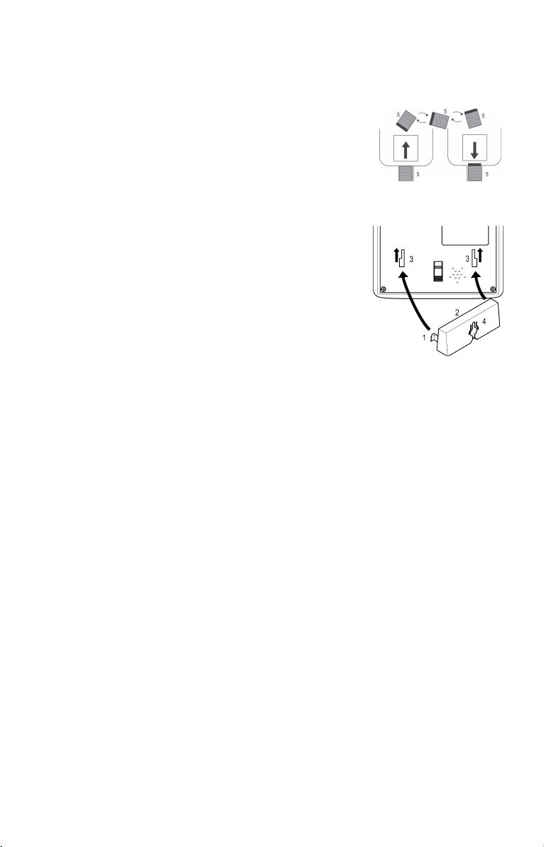
1. Use a flat-blade screwdriver or tip of a pen to lift and remove the battery
compartment door.
2. Insert four AA batteries into the compartment as indicated by the polarity
symbols.
3. Snap the battery compartment door back into place.
When this symbol appears on the display or the display dims, replace the
batteries. Always use 4 new high quality Alkaline AA batteries.
3.2 Connecting the mains power supply
Insert the plug of the power supply into the round socket at the back of the
telephone and plug the power supply into a working mains power point. The
power adaptor must be connected to mains power and the wall switch be
turned on at all times.
CAUTION
Use only the mains adapter supplied with this product. Incorrect adaptor
polarity or voltage can seriously damage the unit.
Adaptor for base:Input: 240 VAC 50 Hz
Output: 9VDC 200 mA
3.3 Connecting the telephone
1. Plug one end of the telephone cable supplied into the TEL. LINE jack at
the back of the telephone base.
2. Plug the other end of the telephone cable into the wall outlet.
3. Plug one end of the curly cord into the socket on the handset.
4. Plug the other end of the curly cord into the left side of the telephone.
5
Page 6
3.4 Wall Mounting
Method A. To fit to an existing telephone wall plate with modular connector
simply,
1. Press and lift out the handset holder on base.
Rotate it 180°, and snap it into place (see A) so it
will hold the handset in place when the phone is
mounted on the wall.
2. Insert the mounting bracket’s two tabs into the
matching slots on the phone’s base. (see fig B)
3. Then press down and slide the bracket upward
until the tabs snap into place.
4. Plug the short telephone line cord (supplied) into
the base of the phone and plug the other end into
the telephone wall plate socket.
5. Position the mounting holes on the base of the
phone over the two protruding screws on the wall
plate. Gently push the phone flush against the
wall plate then slide the phone downwards locking
it into place.
fig A
fig
B
Method
1. Drill two holes vertically, one above the other, 83mm apart, and leave the
2. Follow steps 1 and 2 above.
3. Then press down and slide the bracket upward until the tabs snap into
4. Plug one end of the telephone cable into the TEL. LINE jack at the back
5. Plug the other end of the telephone cable into the telephone socket, then
B. Attach directly to a wall
screws protruding from the wall by 5mm.
place.
of the base.
align the base’s keyhole slots with the screws and slide the phone
downward to secure it.
6
Page 7

4 Setting Up
CID
CID
CID
CID
4.1 Setting the contrast
1. Press the MENU button. The display shows “LCD CONTRAST”.
2. Press the OK button. The display shows the current contrast setting with
values between 1 and 5.
3. Press or to select the contrast level and confirm with OK button.
4. The display now shows to “TIME/DATE”, you can refer to next section to
set the time and date or press
4.2 Setting the TIME and DATE
1. Press and release the MENU button until “TIME/DATE” is shown.
2. Press the OK button. The display shows “ENTER TIME” and the hours
digit is flashing.
3. Select the current hour using the or and confirm with OK button. The
minutes will now flash in the display.
4. Select the required minutes using the or and confirm with OK button.
The display now shows “ENTER DATE” and the month digit is flashing.
5. Select the current month using the or and confirm with OK button.
The day will now flash in the display.
6. Select the current day using the or and confirm with OK button.
7. Exit the set-up mode using the
4.3 Setting country (AUSTRALIA/NEW ZEALAND) mode
The factory preset is AUS.
1. Press and release the MENU button until AUS /NZ is shown.
2. Press the OK button.
3. Select your location (AUS or NZ) by using or and confirm with OK
button.
4. Press
to exit the set-up mode.
Note: Australia Recall/flash time is 100ms. New Zealand Recall/flash time is
600ms, the unit is now set up to insert 0/00 when receiving CID log in
accordance with Telecom NZ requirements.
button to exit the set-up mode.
button.
4.4 Voice Prompts
Voice prompts are provided to make it easy to use the TP170WP. The volume
of the voice prompt can be adjusted with the VOLUME slide switch on the
side of the phone.
If you prefer you may turn off the voice prompt function. NOTE: You will still
hear all the phone book names you recorded.
1. Press and release the MENU button until VOICE is shown.
2. Press the OK button.
3. Using the or to select between VOICE YES or NO and confirm with
OK button.
4. Press
button to exit the set-up mode.
7
Page 8

4.5 Receiver Volume Control
CID
The receiver volume control enables you to adjust the receiver volume on
the handset. Rotate the button on the base to select a comfortable listening
level (1-9), the red LED will turn on.
WARNING
Setting the receiver volume to maximum may, under some situations
cause ear damage. We suggest returning the volume control to the “0”
(OFF) position after each call.
4.6 Hearing Aid Compatibility
This unit is compatible with most inductively coupled hearing aids on the
market. However due to the wide range of hearing aids available we cannot
guarantee that the TP170WP will function error free with every model.
4.7 Receiver Tone Volume Control
You can use the TONE slide switch to adjust high frequency sounds. Words
are clearer and easier to understand. Note: The tone adjustment function will
not work if the receiver volume is set to the minimum level.
4.8 Selecting the ringer melody
1. Press and release the MENU button until RINGER MELODY is shown.
2. Press the OK button, the display shows RINGER MELODY 1.
3. Select the desired RINGER MELODY 1, 2 or 3 using or and confirm
with OK button.
4. Press
to exit the set-up mode.
4.9 Ringer Volume Control
The ringer sound level can be adjusted by sliding the RINGER switch. Select
high (HI), mid (MID) or low (LO) level.
The bright Red light (LED) on the base will flash with all incoming calls.
5. REMOTE PENDANT
The telephone comes with one waterproof emergency pendant which is already
paired with the unit.
Please contact your local re-seller to purchase additional emergency pendants.
These can be used by another person in the house or to have a spare pendant
in more than one room (like bathroom and bedroom).
The following information is for pairing additional pendants only or if you
accidently have deleted the pendant from the “pairing menu”
8
Page 9

5.1 Pairing new pendants to the phone
CID
1. Press and release the MENU button until REMOTE PENDANT is shown.
2. Press the OK button,
3. Select PAIRING or DELETE by pressing the or , and confirm with
the OK button.
5.2 Remote Pendant setting:
If you select PARING, the display will show PAIRING for only 3 seconds.
Immediately press and hold down pendant key for 3 seconds until you see
“PAIRED” on the display.
If after 2 seconds no pendant was successfully paired, the display will show
“PAIRING FAILURE”.
Please repeat above procedure until you have successfully paired the pendant
with the telephone.
You can pair up to 5 pendants to each telephone. Please repeat above
procedures to pair another pendant.
If you have already paired 5 pendants to the phone attempting to pair more,
pendants will result in display showing “FULL”.
5.3 DELETE Devices:
If you select “DELETE”, the unit will DELETE ALL the paired pendants.
You will need to pair all pendants again including the main pendant which
came with the phone.
Press
Upon exiting set-up mode, you should press and hold the pendant button for
3 seconds to make sure that the pendants were successfully paired. If the
phone beeps, press and hold the pendant again to abort the emergency
calling feature
to exit set-up mode.
6. Telephone Operation
6.1 Making a call
1. Pick up the handset or press SPEAKER button (the speaker LED will
light) and wait for a dial tone.
2. Dial the number you wish to call. The display will show the number that
you are dialling. If you dial a number over 14 digits long, it will show the
last 14 digits only.
3. When you have completed your call, hang up the handset or press
SPEAKER button again to release the telephone line.
It is possible to switch from a handset to speakerphone conversation by
pressing the SPEAKER button and picking up or hanging up the handset
accordingly.
9
Page 10

Pre Dialing a Call
1. Dial the number you wish to call the telephone will speak out the numbers
as you dial them (with voice option ON). To correct a number press the
DELETE button for each incorrect digit.
2. Pick up the handset, press CALL BACK or press the SPEAKER button.
6.2 Receiving a Call
When you receive a call, the telephone rings, the Ringer LED flashes, and
the display shows the CALL# and the caller telephone number (with caller id
service activated). The phone will say the name of the caller if the number
matches a name recorded in the phone book, if not, it will say the numbers
of the caller.
This feature allows you to decide to pick up the phone or not depending on
who is calling.
If you want to talk to the caller:
1. Pick up the handset or press SPEAKER button to answer the call.
2. At the end of the call, return the handset to the cradle or press SPEAKER
button again.
Answering a call telephone call with the remote pendant
If you are within a few meters of the TP170WP you can answer an incoming
call by pressing the red button on the remote pendant, the telephone will
answer the call and activate the speakerphone so you can speak to the
caller without picking up the handset. By pressing the red button of the pendant
a second time you will deactivate the speakerphone and return to standby
mode.
This feature is particularly useful if you are relaxing and do not wish to get up
to answer the telephone.
6.3 Speaker Volume Control
You can adjust the speaker volume level that suits you by sliding the VOLUME
switch.
6.4 Last number Redial
To redial the last number called:
1. Lift the handset or press SPEAKER button.
2. Press the REDIAL button.
3. The last number you dialed (manually) will then be can be redialled.
10
Page 11

6.5 Call waiting (Recall button)
CID
You can use the recall function to answer a second call while you are on the
phone. However this service will need to be turned on. For example to turn
on Telstra’s Call Waiting service:
1. Lift the handset or press SPEAKER button.
2. Wait for dial tone then Press *43#
3. You will hear a service announcement then hang up.
To answer a second call while putting the first caller on hold
During a call, you will hear two loud beeps periodically to notify you of another
incoming call. If you wish to answer this call
1. Press RECALL listen for dial tone then Press 2 to put the current call on
hold and talk with the second caller.
2. Subsequent presses of RECALL listen for dial tone then Press 2 will
toggle you between these 2 callers.
6.6 Network Message Waiting Indicator
You need to subscribe to a voice message service (eg Telstra Message Bank)
from your local service provider to use this feature.
When you are unable to answer a call, the incoming call will be forward to a
mail box where the caller can leave a message. The new call LED will blink
and the display will show MESSAGE WAIT to alert you to listen to the stored
message.
The new call LED and the MESSAGE WAIT message will be turned off after
you have listened the message in the mail box.
Or you can press the DELETE button once, the display shows DELETE ?,
press and hold the DELETE button to turn off the new call LED and the
MESSAGE WAIT message.
6.7 Pause
If needed for phone banking or behind a PBX system. You can insert a 3.6
seconds pause while dialing or storing a number into memory. Press REDIAL
button at the desired point in number to insert a pause.
6.8 Storing numbers in the M1 & M2 one touch memories
1. Press and release the MENU button until the STORE NUMBER is shown.
2. Press the OK button. The cursor will flash in the first position.
3. Enter the required telephone number with a maximum of 22 digits using
the number pad and confirm with OK button.
4. Press M1 or M2.
5. Confirm with OK button. The number has now been saved and display
show SAVED!.
6. Repeat step 2 to 5 to store other numbers for other memory buttons or
press
button to exit.
11
Page 12

To dial the numbers in the emergency MEMORY Buttons, simply pick up the
handset or press SPEAKER button and press M1 or M2.
Note: the numbers stored in M1 and M2 memory buttons are for manual
dialing only and are not dialled in the emergency call function.
7. The Phone Book
7.1 Storing numbers in the phone book
You can enter up to 30 names and numbers into the Phone book and
choose which of those numbers will be dailled when the Emergency
call function is activated and in which order they will be dialled.
1. Press and release the MENU button until STORE NUMBER is shown.
2. Press the OK button. The cursor will flash in the first position.
3. Enter the required telephone number including the area code (max of 22
characters) press OK button to confirm (both the erase feature and pause
feature can be used when storing the telephone number).
4. Enter the required name (max 16 characters). The next section will explain
how to enter names.
5. Confirm with OK button. The display now shows EMERGENCY OFF.
6. Select EMERGENCY ON or EMERGENCY OFF using the or and
confirm with OK button.
• If you selected EMERGENCY OFF and press OK, SAVED is shown
and the unit announces “Name Recording for phone book”. That means
the phone number is stored only for normal memory phone dial out,
not for emergency call dial out
To record voice (example ‘John’), hold down OK button, speak clearly
into the microphone after a beep and “VOICE” symbol is flashing.
Release the button when you finished or the unit will stop recording
after 3 seconds. The voice prompt will then be played automatically.
[Recording the Voice is necessary for the personalized talking caller id
and talking phone book feature].
• If you selected EMERGENCY ON, and press OK, “LOCATION” is
shown. Select the required location by pressing or and confirm
with OK button, if the location is in use, the display shows
OVERWRITE? confirm with OK or select another location with or
. Press the OK button and SAVED! is shown.
12
Page 13

WARNING
CID
CID
Selecting the correct location is very important as this feature determines
the sequence in which the emergency telephone numbers are dialled.
Location 1 will be dialled first, then 2, then 3 etc.
WARNING: If you choose to overwrite a location, the previously stored
number will be erased.
The unit announces “Name Recording for phone book” and the “SOS”
symbol is shown. That means the phone number is stored for a general
phone and emergency’s call dial out.
To record voice (example ‘this is John’), hold down OK button, speak
clearly into microphone after a beep and “VOICE” symbol is flashing.
Release the button when you finished or the unit will stop recording
after 3 seconds. The voice prompt will then be played automatically.
[Recording the Voice is necessary for the personalized talking caller id
and talking phone book feature.
7. You can repeat step 2 to 6 to enter more numbers or press
button to
exit.
Important: You can only use the phone book features, in the phone book
mode. If the symbol is off, press
button once to enter phone book
mode.
How to enter names
By repeatedly pressing the appropriate button, upper case letters as well as
numbers and special characters can be entered.
Overview:
Button Letters/symbols
1................................. [Space character] + & - / 1
2................................. A B C 2
3................................. D E F 3
4................................. G H I 4
5................................. J K L 5
6................................. M N O 6
7................................. P Q R S 7
8................................. T U V 8
9................................. W X Y Z 9
*................................. ‘ @ ( ) *
0................................. , . : ; ? 0
#................................. $ _ % ! #
Incorrect entries can be deleted using the DELETE button. To do this, move
the cursor to the correct position using or and then press DELETE
button.
13
Page 14

7.2 To review the Phone Book Memory
CID
CID
CID
1. Press and release
button until the phone symbol is shown.
2. Review the stored phone number by pressing or , or enter the first
letter of the name of the person you wish to call. After a short time, the
display will display the first stored telephone number and say the name if
it was recorded. You can now search for further numbers under this letter
by pressing .
Notes:
• If no telephone numbers are stored, the display will show EMPTY.
• After you view all the call in memory, the display will show END OF LIST.
7.3 To dial a number from the Phone Book:
1. With the required telephone number showing on the display, press CALL
BACK button. The telephone dials out the displayed telephone number
automatically in speakerphone mode.
2. The display shows the telephone number and call timer.
OR
1. Pick up the handset or press SPEAKER button (the speaker light will turn
on) and wait for a dial tone.
2. Press and release
button, symbol is shown.
3. Review the stored phone number by pressing or .
4. Press CALL BACK button.
7.4 Recording / Editing / Deleting voice prompt of name of phone
book
With caller ID service activated, when an incoming call is received, the unit
will display and announce the caller's phone number (unless it is blocked). If
the caller's phone number is stored in the phone book, caller's name will be
displayed too.
If the voice prompt is recorded for this phone number, the unit will announce
the voice prompt instead of the caller's phone number.
1. Press and release the MENU button until the NAME RECORDING is
shown.
2. Press the OK button. A list of the phone book entries will be displayed.
3. Press or to select the list you like to record a voice or name for it.
4. To record or edit the voice, hold down OK button. After the beep, speak
clearly into the microphone. Release the button when you are finished
(max recording time is 3 seconds.) The new voice prompt will then be
replayed automatically.
To delete the voice prompt recorded, press DELETE button while the
voice prompt is playing.
5. Repeat steps 3 to 4 to edit or delete entries or exit the set-up mode by
pressing the
button.
14
Page 15

7.5 To Edit Phone Book Memories
CID
CID
CID
1. Press and release
button until phone book symbol is shown.
2. Select the required location by pressing or .
3. Press and hold MENU button for two seconds. The display will show
EDIT?.
4. Press OK button, the first digit of the selected phone number will flash.
5. You can move the cursor to the required position by pressing or . To
delete the digit, press DELETE button, or press any numeric key to replace
the digit, confirm with OK button. Then the display shows the flashing first
letter of the name.
6. Move the cursor to the required position by pressing or . To delete the
letter, press DELETE button, or press any numeric key to replace the
name, and confirm with OK button, EMERGENCY ON or OFF is shown.
7. If the display shows EMERGENCY OFF, and you want to change it as an
emergency’s call dial out, select EMERGENCY ON by pressing or ,
and confirm with OK button, now LOCATION is shown. Select the required
location by pressing or and confirm with OK button, if the location is
in use, now display shows OVERWRITE?, confirm with OK, SAVED! is
shown.
If you select EMERGENCY OFF and confirm with OK, SAVED! is shown.
Warning: Selecting the correct memory sequence is very important
as this feature determines the sequence in which the numbers will
be dialled in the emergency feature. Location 1 will be dialled first,
then 2, then 3 etc.
Warning: If you choose to overwrite a location, the previously stored
number will be erased.
8. You can repeat step 2 to 7 to edit more numbers or press
7.6 To Delete the Phone Book Memory
1. Press and release
button, symbol is shown.
2. Select the required location from the phone book by pressing or .
3.
To delete single memory
, press DELETE button once. The display will
show the DELETE?. Press DELETE button for 2 seconds. The telephone
number and name will be deleted and the display will now show another
number from the phone book.
To delete all entire memory
, press and hold DELETE button until the
display shows DELETE ALL?. Press DELETE button for 2 seconds until
EMPTY appears on the display.
15
to exit.
Page 16

8 Emergency Call feature
THE EMERGENCY CALL FUNCTION WILL NOT OPERATE UNLESS ALL THE
PROCEDURES IN THE USER GUIDE HAVE BEEN COMPLIED WITH.
This feature allows you to summon assistance from the people in emergency
phone list.
8.1 Emergency Message
Two options are provided for your emergency message:
A. A pre-record message "This is an emergency call, to accept this call
press 0". This message will be played unless you decide to record your
own message.
B. Your own recording (max. recording time 20 secs).
This can be any message of your choice, but should always end with the
phrase "to accept this call press 0 now.
8.2 To record your emergency message
1. Press and release the MENU button until the RECORD MESSAGE is
shown.
2. Press and hold the OK button. After the beep start your message (keep a
distance of 15 cm from the telephone so that you can speak into the
microphone).
3. Release the OK button after you have finished your emergency message.
The message will now play back for you to review.
8.3 To check your emergency message
You can check the emergency message at any time.
1. Press and release the MENU button until the CHECK MESSAGE is shown.
2. Then press the OK button to play back the message.
8.4 To delete your own emergency message and use the pre-
recorded message
If you have recorded your own message, you can delete this and by doing so
use the pre-recorded message.
1. Press and release the MENU button until the CHECK MESSAGE is shown.
2. Then press the OK button to play back the message.
3. During the playback, press DELETE button. Your own message will be
deleted and you will now use the pre-recorded emergency message.
16
Page 17

8.5 To activate the Emergency Call function:
1. Press and hold the button on the pendant or the SOS emergency button
on the telephone for three seconds. The telephone will beep loudly for 15
seconds. (If during this time the emergency SOS button on the phone, or
the button on the pendant is pressed for more than three seconds, the
emergency call will be cancelled. If the key is not pressed, the telephone
will dial out the emergency numbers automatically in speakerphone mode.
2. The telephone dials out the first emergency number (stored in the phone
book emergency location 1), and then announces the emergency message
continuously.
• If during 60 seconds the called party acknowledges the call by pressing
0 on their phone, the speakerphone will be activated for 3 minutes.
• If 0 is not pressed within 60 seconds, the TP170WP will terminate the
call, then after a further 30 seconds dial the next emergency number
automatically in speakerphone mode.
WARNING
1. If NO emergency numbers have been programmed, the telephone
will not dial anything. It will just beep loudly for 15 seconds when
the SOS button on the phone or the button on the pendant is pressed.
2. The pendant must be within the range of the telephone to activate
the emergency feature. You should check that there are no structural
obstacles, heavy concrete walls between the pendant and the
telephone.
3. When the button on the pendant is pressed, the red light (LED) will
light up for as long as the key is pressed. If the led does not light up
it is necessary to replace the battery.
4. To cancel the emergency feature, press and hold the SOS button on
the telephone or the pendant for more than three seconds.
5. The emergency feature will automatically stop when all the emergency
numbers have been dialled twice or if the receiver presses 1 and 2
after the 0 key. (The reason for interrupting the call after 3 minutes
is for safety in case a receiving party presses 0 but for any reason is
unable to receive the message, in case of mobile phone drop out for
example).
Note: The emergency feature will automatically stop when all the
emergency numbers have been dialed or if the receiving party has pressed
0. When the receiver presses 1 and 2 after the 0 key, the unit will stay in
speaker mode or you can hang up the receiver.
6. The receiving party must use a tone dialing phone, (standard feature
on most telephones) to press “0”.
17
Page 18

9. Caller ID
CID
Important: To use Caller ID functions the CLIP symbol must be on. If the
CLIP symbol is not visible on the display, press the
9.1 Receiving a Call (Can be stored up to 64 calls)
• If an incorrect, invalid or incomplete Caller ID signal is received, the display
shows -ERROR-.
• If only the caller's phone number is received, the display shows the caller's
phone number with the time and date it was received. The NEW symbol
turns on and NEW CALL LED blinks.
Notes:
1. CALL#01 means this data is stored in Caller ID memory location #01.
2. The calling time and date are immediately recorded from the real-time
clock.
• If the callers number is not available due to the caller’s restriction, the
display shows -PRIVATE CALL- with the time and date received. The
NEW symbol turns on and NEW CALL LED blinks.
• If the callers number is not available, the display will show -OUT OF
AREA- with the call’s time and date. The NEW symbol turns on and NEW
CALL LED blinks.
• If a overseas call is received, the display will show -LONG DISTANCE-
with the calls time and date. The NEW symbol turns on and NEW CALL
LED blinks.
Notes:
1. If the Caller ID memory is full, the oldest data will be removed on a firstin/first-out basis.
2. If the Caller ID information received duplicates another call in memory,
the time/date will be updated and the “REPEAT” symbol will be lit.
3. If no key is pressed within 20 seconds, the display will display the total
call counter, new call counter, current time and date.
button once.
9.2 View the Caller ID Memory
Press to review more recent calls. The CALL# will increase.
After you view the most recent data in memory, the display will show END
OF LIST.
Press to review older calls. The CALL# will decrease.
After you view the oldest data in memory, the display will show END OF
LIST.
If the data in memory is being reviewed for the first time, the NEW symbol
will be lit. The NEW CALL LED will off if you review the data.
If no key is pressed within 20 seconds, the display will display the total call
counter, new call counter, current time and date.
18
Page 19

9.3 Deleting Numbers from the Caller ID Memory
1. Select the required Caller ID memory location by using the or button.
2.
To delete single memory
show the DELETE?. Press DELETE button for 2 seconds. The data for
that call will be erased, and the CALL# and Caller ID information will be
updated.
To delete all entire memory
display shows DELETE ALL?. Press DELETE for 2 seconds until NO
CALLS appears on the display.
Both the total call and new call counters will reset to zero, and the current
time and date will be displayed.
, press DELETE button once. The display will
, press and hold DELETE button until the
9.4 CALL BACK (Redial) from the Caller ID Memory
With the handset on the base. Select the required Caller ID memory location
by pressing or . Press CALL BACK button, the speakerphone will
automatically dial the selected number.
Or
Pick up the handset, select the required Caller ID memory location by pressing
or , then press CALL BACK button.
9.5 Copy from the Caller ID to the Phone Book
You can copy Caller ID information to the phone book while you are reviewing
the Caller ID information.
1. Select the required Caller ID memory location by pressing or .
2. Press and hold MENU button for two seconds, display will show COPY
TO MEMORY ?.
3. Press OK button again, display will show SAVED!.
19
Page 20

10. Important Information
10.1Periodic testing
Remote Pendant
We recommend you check and test the remote pendant and SOS button
function every month. To ensure that it is working correctly.
The remote pendant battery should last for up to 2 years but we recommend
changing it every 12 months or sooner if the red light on the pendant becomes
dim or the operating range reduces. Replacement batteries for the pendant
can be obtained from most supermarkets.
Testing the remote pendant battery
1. Press and hold the button (1) on the remote pendant
unit briefly. The LED (2) lights up.
2. If the LED (2) no longer lights up when the button
is press and held, replace the battery.
Replacing the battery in the remote pendant
1. Remove the screw on the rear side of the remote pendant using a small,
cross tip screwdriver.
2. Insert the tip of a small screwdriver in the notch (3) and carefully open the
housing.
3. Replace the 12volt battery with a Duracell 23A 12-Volt Alkaline Battery,
pay attention to the correct polarity.
4. Close the housing and replace the screw.
5. Test the remote by pressing and holding the button for 3 seconds the
phone will begin to beep. Cancel by pressing and holding the button on
the pendant for 3 seconds.
2
1
10.2Battery Backup on the phone base
The TP170WP requires that 4 AA Alkaline batteries be fitted in the phone
and the power adaptor be connected to mains power socket and be turned on
at all times.
The Battery warning symbol on the phone display will indicate when the 4 AA
batteries in the phone base need replacing. The batteries fitted to the phone
base will power the unit for up to 12 hours if there is a mains power failure or
power for some reason is disconnected to the phone.
These batteries are not the rechargeable type and therefore if your mains
power has been turned off for an extended period or the power supply to the
phone has been unplugged from mains power you should replace these
batteries with 4 new quality AA Alkaline batteries.
20
Page 21

10.3 Consumer Support and Troubleshooting
If you feel this product is not working correctly please consult this user guide
and ensure that you are using the product in accordance with the instructions.
Remove all extra telephone equipment and connect only this telephone directly
to the telephone socket. If the fault is still present, connect another telephone
to the telephone socket. The results will show you whether the fault lies with
this unit or with the telephone line. If the product is working correctly the fault
is on the telephone line. Please contact your network operator for assistance
In the case of technical problems with this product please consult our website
for further information or contact us for a prompt response to your enquiry. If
our customer support team think the unit may be faulty you will be asked to
return it directly to us with a copy of the purchase receipt
10.4 Cleaning and care
The surface of the case can be cleaned with a dry, soft, lint-free cloth. Never
use cleaning agents, particularly aggressive solvents. Apart from occasional
cleaning of the case, no other care is necessary. The rubber feet of the base
station are not resistant to all cleaning agents. The telephone feet do not
normally leave any marks on the surface. However, on account of the multitude
of varnishes and surface finishes used, surface marks caused by the feet of
the unit cannot be ruled out, therefore we can not be held responsible for
possible damage to furniture or the like.
10.5Warranty Information
(a)
Warranty
Oricom warrants that the product is free from defects in materials and
workmanship for a period of 12 months effective from the date of purchase.
This warranty in no way affects your statutory warranty under the Trade
Practices Act 1974 or any other similar legislation. It is important that you
read the Warranty Card as it contains full and additional details of the warranty,
limitation of warranty and conditions for receiving the warranty services during
the warranty period. The Warranty Card is located in the package. If you
cannot locate the Warranty Card, please contact our Customer Support Service
on 1300 889 785.
(b) Exclusion and limitation of liability
Oricom will not be in breach of a warranty or condition expressly stated in
this User Guide or the Warranty Card or implied by the Trade Practices Act
and excludes any liability arising under any statutory or common law for
damages or any other remedy if the damage occurs as a result of:
(i) failure by you to follow the instructions in the User Guide for the
installation and proper functioning of the product;
21
Page 22

(ii) negligence on your part or misuse by you of the product;
(iii) any un-controlled external cause to the phone not functioning including
but not limited to electricity failure, lighting, over voltage;
(iv)non adherence by you to the warnings in the User Guide and the User
Guide generally; and (v) modification to the product or services carried
out to the product by anyone other than Oricom or on Oricom’s behalf.
Oricom will not be liable for consequential losses including loss of profits
arising from a cause of action in contract, tort or any other statutory or common
law (except where a statute or any law prohibits this exclusion). The warranty
does not extend to damage caused by misuse, negligence, excessive voltage,
faults on the telephone line or lightning. This warranty in no way affects your
statutory rights. Full details of the warranty are contained in the enclosed
warranty card.
Australia
Oricom International Pty Ltd
Locked Bag 658
South Windsor NSW 2756
Customer support
Email: support@oricom.com.au
Web: www .oricom.com.au
Fax: (02) 4574 8898
Ph: 1300 889 785
New Zealand
Atlas Gentech (NZ) Ltd,
Private Bag 14927,
Panmure,
Auckland
Customer Support
Email: support@atlasgentech.co.nz
Fax (09) 5742722
Ph: 0900 50025 (T oll Call)
For further information about the Oricom range of products please visit
our website.
22
Page 23

Page 24

2LMC70YY
 Loading...