

Page 1
Amplified speaker Phone TP110
User guide keep for future reference
Page 2

1 General Information and Warnings
• The telephone is designed for indoor use only. Do not install the telephone
in areas where there is the risk of an explosion, excessive exposure to
smoke, dust, vibrations, chemicals, moisture and heat.
• Do not use your telephone during an electrical thunderstorm as it is
possible to get an electric shock. Refer to information contained in Telstra
White pages directory.
• The earpiece of the handset may attract small metal objects such as
staples and pins. Care should be taken when placing the handset near
these items
• Setting the receiver volume to maximum may, under some situations
cause ear damage. We suggest returning the handset volume control to
the 0 position after each call.
• Do not install in damp locations such as a bathroom or laundry, do not
expose the unit to direct sunlight.
Notes for operation in New Zealand
The grant of a Telepermit for any item of terminal equipment indicates only
that Telecom has accepted that the item complies with the minimum conditions
for connection to its network. It indicates no endorsement of the product by
Telecom, nor does it provide any sort of warranty. Above all, it provides no
assurance that any item will work correctly in all respects with another item
of Telepermitted equipment of a different make or model, nor does it imply
that any product is compatible with all of Telecom’s network services. This
device may be subject to ringing or bell tinkle when certain other devices are
connected to the same line. If this occurs, the problem should not be referred
to the Telecom Faults service.
REN (RN for New Zealand)
The REN (Ringer Equivalence Number) or (RN) is of significance only if you
wish to connect more than 1 telephone to your telephone line. A standard
telephone line has a maximum REN capacity of 3 (RN of 5). It is possible to
connect 3(5) devices with a REN of 1 (RN of 1)z with no degradation to the
product’s performance. Exceeding this limit may cause the volume of the
ringer in any phone to decrease or not ring at all.
Caller ID
Customers using non Telecom toll services should not use the dial back
feature for local calls as this will incur a charge only the 7 digit number
should be dialled. Some of the CID services listed may not be available in
New Zealand.
2
Page 3
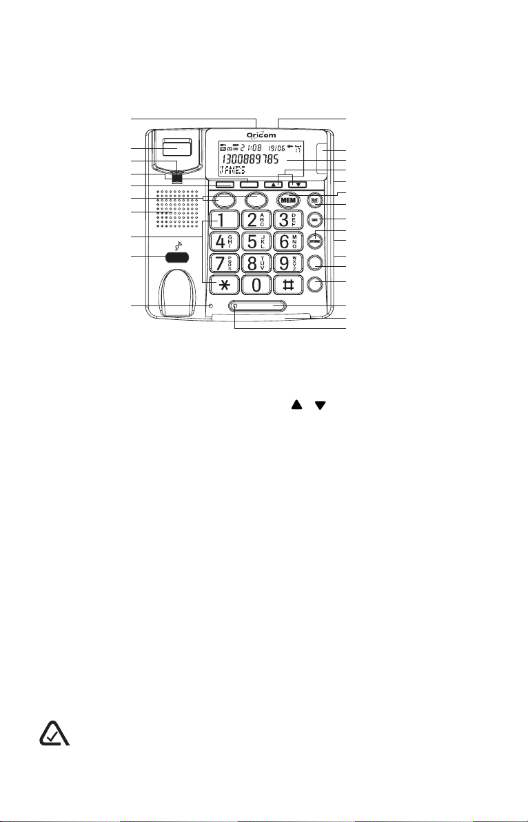
2 Location of controls
1
2
3
4
5
6
7
8
9
3 4 5
10
1. Telephone Line Jack
2. Hook switch
3. Handset Holder
4. Delete Button
5. Call Back Button
6. Memory Buttons (M1, M2)
7. Speaker
8. Keypad
9. Handset volume control
10. Receiver volume LED
11. Flash time Switch
12. New Call LED
13. Display
CALL BACK
DELETE
M1 M2
SPEAKER
11
12
13
14
15
16
17
18
19
20
21
RECALL
22
23
REDIAL
24
25
26
14. / Buttons
15. Ringer Hi/Lo/Off Switch
16. Memory Button
17. Phonebook Button
18. Caller ID Button
19. Store Button
20. Tone Hi/Lo Switch
21. Volume Hi/Lo Switch
22. Recall Button
23. Redial Button
24. Speaker Button
25. Ringer LED
26. Speaker LED
N13134
The A-Tick symbol indicates that this product complies with all current Australian ACMA
standards.
3
Page 4

3 Installation
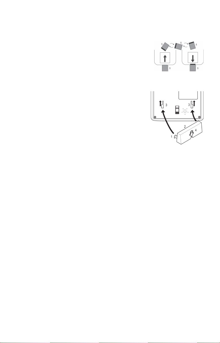
3.1 Installing batteries (supplied) in the phone
You must install 4 AA Alkaline batteries (supplied) in the phone
base, or the display and Caller ID will not work.
Warnings
Before opening the battery compartment, make sure the telephone is
disconnected from the telephone line and the mains power supply.
1. Use a flat-blade screwdriver or tip of a pen to lift and remove the battery
compartment door.
2. Insert four AA batteries into the compartment as indicated by the polarity
symbols.
3. Snap the battery compartment door back into place.
When this symbol appears on the display or the display dims, replace
the batteries. Always use 4 new high quality Alkaline AA batteries.
3.2 Connecting the telephone
1. Plug one end of the telephone cable supplied into the TEL. LINE jack at
the back of the telephone base.
2. Plug the other end of the telephone cable into the wall outlet.
3. Plug one end of the curly cord into the socket on the handset.
4. Plug the other end of the curly cord into the left side of the telephone.
4
Page 5
3.3 Wall Mounting
Method A. To fit to an existing telephone wall plate with modular connector
simply,
1. Press and lift out the handset holder on base.
Rotate it 180° , and snap it into place (see A) so
it will hold the handset in place when the phone
is mounted on the wall.
2. Insert the mounting bracket’s two tabs into the
matching slots on the phone’s base. (see fig B)
3. Then press down and slide the bracket upward
until the tabs snap into place.
4. Plug the short telephone line cord (supplied) into
the base of the phone and plug the other end
into the telephone wall plate socket.
5. Position the mounting holes on the base of the
phone over the two protruding screws on the wall
plate. Gently push the phone flush against the
wall plate then slide the phone downwards
locking it into place.
Method B. Attach directly to a wall
1. Drill two holes vertically, one above the other, 83mm apart, and leave the
screws protruding from the wall by 5mm.
2. Follow steps 1 and 2 above.
3. Then press down and slide the bracket upward until the tabs snap into
place.
4. Plug one end of the telephone cable into the TEL. LINE jack at the back
of the base.
5. Plug the other end of the telephone cable into the telephone socket, then
align the base’s keyhole slots with the screws and slide the phone
downward to secure it.
fig A
fig B
5
Page 6

4 Basic settings
1. After installing the batteries, the display should flash the word ENGLISH”.
If not press and hold for approximately 4 seconds.
2. Select the desired language using or . Press DELETE button.
3. Select the desired contrast setting (2=Default) using or . Press
DELETE button.
4. Set the hour (00-23) using or . Press DELETE button.
5. Set the minute using or . Press DELETE button.
6. Set the day using or . Press DELETE button.
7. Set the month using or . Press DELETE button.
4.1 Display (LCD) Contrast/Time Setting
If you wish to change the language, LCD contrast or time setting at a later
date, press and hold or button for approximately 4 seconds and repeat
steps 2-8 above.
4.2 Select country version
1. For New Zealand Select Recall = 600 on the switch on the rear side of
the unit, New Zealand Recall/flash time is 600ms, the unit is now set up
to insert 0/00 when receiving CID log in accordance with Telecom NZ
requirements. There may be some incoming international calls which result
in number lengths of less than 10 digits, but these are expected to be in
the minority.Typical examples are those from the Pacific Islands. These
numbers will be displayed as national numbers. Numbers longer than 14
digits will not be displayed correctly and Dial back function should not be
used.
Or for Australia Select Recall = 100.
2. Lift and replace the handset to initialize.
NOTE: If the switch is in the incorrect position Caller ID and the
recall function will not operate correctly.
5. Operation
When the telephone is not in use, the date and time, number of new and
total number of calls stored in the Caller ID memory will be shown in the
display. The display will show the caller number (and name if available).
6
Page 7

5.1 Making a call
1. Pick up the handset or press SPEAKER button (the speaker LED will
light) and wait for a dial tone.
2. Dial the number you wish to call. The display will show the number that
you are dialling. If you dial a number over 14 digits long, it will show the
last 14 digits only.
3. When you have completed your call, hang up the handset or press
SPEAKER button again to release the telephone line.
It is possible to switch from a handset to speakerphone conversation by
pressing the SPEAKER button and picking up or hanging up the handset
accordingly.
Pre Dialing a Call
1. Dial the number you wish to call . To correct a number press the DELETE
button for each incorrect digit.
2. Pick up the handset or press the SPEAKER button.
5.2 Receiving a Call
When you receive a call, the telephone rings, the Ringer LED flashes, and
the display shows the CALL # and the caller telephone number (with caller
ID service activated).
This feature allows you to decide to pick up the phone or not depending on
who is calling.
If you want to talk to the caller:
1. Pick up the handset or press SPEAKER button to answer the call.
2. At the end of the call, return the handset to the cradle or press SPEAKER
button again.
5.3 Redial function
If a number that you have dialled is engaged or you were unable to get
through to anybody. The last number dialled will be saved in the telephone
automatically. To use the redial facility, proceed as follows:
1. Lift the handset or press SPEAKER button .
2. Press the REDIAL button. The last saved redial number will now be dialled.
5.4 Pause
If needed for phone banking or behind a PBX system. You can insert a 3.6
seconds pause while dialing or storing a number into MEM. Press REDIAL
button at the desired point in number to insert a pause.
5.5 Recall and call waiting
The recall button timing can be switched between either 100ms (AUS) /
600ms (NZ), using the Recall switch located on the rear side of the handset.
7
Page 8

5.6 How To Turn on Telstra call waiting (Australia)
You can use the RECALL button to answer a second call while you are on
the phone. However this service will need to be turned on. For example to
turn on Telstra’s Call Waiting service:
1. Lift the handset and wait for dial tone then Press *43#.
2. You will hear the service message and then hang up.
Take two different calls at the same time
During a call, you will hear two loud beeps periodically to notify you of another
incoming call. If you wish to answer this call
1. Press Recall button listen for dial tone then Press 2 to put the current
call on hold and talk with the second caller.
2. Subsequent presses of Recall button listen for dial tone then Press 2
will toggle you between these 2 callers.
5.7 Call Timer
Immediately after dialling a telephone number a call timer will be shown on
the display. The timer is a simple way to help you keep track of how long the
call lasts.
5.8 Ringer Volume Control
The ringer sound level can be adjusted by sliding the RINGER switch. Select
high (HI) or soft (LO) sound level. When you don’t want to be disturbed, slide
the RINGER switch to the Off position.
The bright Red light (LED) on the base will flash with all incoming calls.
5.9 Volume Control
Speaker Volume Control
You can adjust the speaker volume level that suits you by sliding the VOLUME
switch.
Earpiece volume amplification control
The volume control enables you to adjust the earpiece volume on the handset.
Rotate the volume switch on the base to select a comfortable listening
level (1 lowest-9 loudest), the red LED will turm on.
WARNING
Setting the receiver volume to maximum may, under some situations
cause ear damage. We suggest returning the volume control to the 0
position after each call.
8
Page 9

6.0 Receiver Tone Volume Control
You can use the TONE slide switch to adjust high frequency sounds. Words
are clearer and easier to understand. Note: The tone adjustment function
will not work if the receiver volume is set to the minimum level.
6.1 Hearing Aid Compatibility
This unit is compatible with most inductively coupled hearing aids on the
market. However due to the wide range of hearing aids available we cannot
guarantee that the TP110 will function error free with every model.
6.2 The Phone Book
The Phone Book will store 32 telephone numbers (22 digits max) and their
associated names (16 characters max) with entries arranged alphabetically.
A stored phone number can be dialled using fewer keystrokes than if dialled
manually. If you subscribe to a Caller ID service, the name/number of the
caller will be shown when you receive an incoming call (only for those numbers
stored in the Phone Book or M1/M2 memories).
6.2.1 Storing names/numbers
1. Press .
2. Press STORE .
3. Press STORE again.
4. Enter the telephone number to be stored (up to 22 digits).
5. Enter the name (up to 16 characters). Press the corresponding number
button one or more times for the first letter (see the table above).
6. Press STORE.
Press STORE.
Each number key has been allocated certain characters.
Button Letters/symbols
1 ....... [Space character] + & - / X 1
2 ....... A B C 2 Å Ä Æ æ å ä ß
3 ....... D E F 3 ë
4 ....... G H I 4 ï
5......... J K L5
6 ....... M N O 6 Ñ ñ Ö c ö
7 ....... P Q R S 7
8 ....... T U V 8 Ü ü
9 ....... W X Y Z 9
* ....... ‘ @ ( ) * < >
0 ....... , . : ? = 0
# ....... $ _ % ! #
È
£
Ë
Î
ÐÓ
ø
Ù
Ö
9
Page 10

6.2.2 Dialling from the Phone Book
1. Press .
2. Scroll to the required memory location using or . To quick-search in
the Phone Book press the corresponding number button one or more
times for the first letter (refer to the table on the previous page).
3. Press CALL BACK or SPEAKER to dial the displayed number. If you do
nothing the phone will return to standby mode.
6.2.3 Changing phone numbers/names
1. Press .
2. Scroll to the required memory location using or .
3. Press and hold STORE until EDIT? is displayed. Press STORE.
4. Changes to the displayed telephone number can be made using DELETE
and or . Press STORE.
5. Changes to the displayed name can be made using DELETE and or
.
6. Press STORE to confirm the changes.
6.2.4 Deleting a phone book entry
1. Press .
2. Scroll to the required memory location using or .
3. Press DELETE. DELETE? will be displayed.
4. Press and hold DELETE until the displayed telephone number
disappears.
7 Using the phone memories
The telephone also has 12 additional memory locations for frequently dialled
telephone number.
7.1 Storing M1 and M2 Memories
1. Press STORE button.
2. Enter the telephone number to be stored (up to 22 digits). Press STORE
button.
3. Enter the name (up to 16 characters). Press the corresponding number
button one or more times for the first letter (see the above table). Press
STORE button.
4. Press either M1-M2 to store the number.
7.2 Dialling using M1 and M2 Memories
1. Lift the handset or press SPEAKER button and wait for a dialling tone.
2. Press either M1-M2, the stored telephone number will now be dialled.
10
Page 11

7.3 Storing numbers in Memory locations 0-9
1. Press STORE button.
2. Enter the telephone number to be stored (up to 22 digits). Press STORE
button.
3. Enter the name (up to 16 characters) . Press the corresponding number
button one or more times for the first letter (see the above table). Press
STORE button.
4. Press either 0-9 to store the number.
7.4 Dialling numbers in Memory locations 0-9
1. Lift the handset or press SPEAKER button and wait for a dialling tone.
2. Press MEM button.
3. Select a memory location by pressing the relevant keypad digit 0-9.
8 Caller ID
Caller ID allows you to see who is calling before you answer a call and to
see who has called in your absence. If the number is stored in the indirect
memory, its associated name will be displayed instead. The CID memory
will store up to 32 name/telephone numbers stored chronologically. The
sequence number is shown in the top right-hand side of the display.
When the memory is full, the oldest number will be deleted automatically as
the new call is logged. New calls are indicated in plain text in the display and
flashing of the red New Call indicator light.
Please note!
In order for numbers to be shown, the Caller ID service must be provided by
your network operator and a current subscription in place. Contact your
telephone service operator for more information.
8.1 Retrieving and dialling CID numbers
1. Press CID button to select caller-id mode.
2. Press either or to review the numbers stored in the Caller ID memory.
3. To dial a displayed telephone number either press CALL BACK OR
SPEAKER, the displayed telephone number will now be dialled. If you do
nothing the phone will return to standby mode.
11
Page 12

8.2 CID Call Types
Besides showing telephone numbers, the display can show a number of
messages:
OUT OF AREA It is an International call or a call from a PBX (no
information received).
PRIVATE Information on the number is blocked. The call could also
be from a PBX.
NEW Number not previously seen.
Several calls have been received from the same caller.
8.3 Deleting Numbers
1. Scroll to the telephone number you wish to erase using or .
2. Press DELETE button, “DELETE?” will be displayed, alternatively press
and hold DELETE button until the display shows “DELETE ALL?”.
3. Press and hold DELETE button until the number disappears.
8.4 Transferring Numbers to the Phone Book
1. Scroll to the telephone number you wish to copy using or .
2. Press STORE.
3. Press STORE again.
4. Name can later be added according to the chapter Changing phone
numbers/names.
9 Important Information
9.1 Consumer Support and Troubleshooting
If you feel this product is not working correctly please consult the user guide
and ensure that you are using the product in accordance with the instructions.
Remove all extra telephone equipment and connect only this telephone
directly to the telephone socket. If the fault is still present, connect another
telephone (if available) to the telephone socket. The results will show you
whether the fault lies with this unit or with the telephone line. If the product is
working correctly the fault is on the telephone line. Please contact your
network operator for assistance
In the case of technical problems with this product please consult our website
for further information or send us an email for a prompt response to your
enquiry.
12
Page 13

9.2 Warranty Information
(a) Warranty
Oricom warrants that the product is free from defects in materials and
workmanship for a period of 12 months effective from the date of purchase.
This warranty in no way affects your statutory warranty under the Trade
Practices Act 1974 or any other similar legislation. It is important that you
read the Warranty Card as it contains full and additional details of the warranty,
limitation of warranty and conditions for receiving the warranty services during
the warranty period. The Warranty Card is located in the package. If you
cannot locate the Warranty Card, please contact our Customer Support
Service on 1300 889 785.
(b) Exclusion and limitation of liability
Oricom will not be in breach of a warranty or condition expressly stated in
this User Guide or the Warranty Card or implied by the Trade Practices Act
and excludes any liability arising under any statutory or common law for
damages or any other remedy if the damage occurs as a result of:
(i) failure by you to follow the instructions in the User Guide for the
installation and proper functioning of the product;
(ii) negligence on your part or misuse by you of the product;
(iii) any un-controlled external cause to the phone not functioning including
but not limited to electricity failure, lighting, over voltage;
(iv) non adherence by you to the warnings in the User Guide and the
User Guide generally; and
(v) modification to the product or services carried out to the product by
anyone other than Oricom or on Oricom’s behalf.
Oricom will not be liable for consequential losses including loss of profits
arising from a cause of action in contract, tort or any other statutory or
common law (except where a statute or any law prohibits this exclusion).
The warranty does not extend to damage caused by misuse, negligence,
excessive voltage, faults on the telephone line or lightning. This warranty in
no way affects your statutory rights. Full details of the warranty are contained
in the enclosed warranty card.
13
Page 14

9.3 Cleaning and care
The surface of the case can be cleaned with a dry, soft, lint-free cloth. Never
use cleaning agents, particularly aggressive solvents. Apart from occasional
cleaning of the case, no other care is necessary. The rubber feet of the base
station are not resistant to all cleaning agents. The telephone feet do not
normally leave any marks on the surface. However, on account of the
multitude of varnishes and surface finishes used, surface marks caused by
the feet of the unit cannot be ruled out. The manufacturer can therefore not
be held responsible for possible damage to furniture or the like.
Australia
Oricom International Pty Ltd
ABN 46 086 116 369
Locked bag 658
South Windsor, NSW 2756
Customer supporCustomer suppor
Customer suppor
Customer supporCustomer suppor
Email: support@oricom.com.au
Web: www.oricom.com.au
Ph: 1300 889 785
Fax: (02) 4574 8898
tt
t
tt
New Zealand
Atlas Gentech (NZ) Ltd,
Private Bag 14927,
Panmure,
Auckland
Customer SupporCustomer Suppor
Customer Suppor
Customer SupporCustomer Suppor
Email: support@atlasgentech.co.nz
Fax (09) 5742722
Ph: 0900 50025 (Toll Call)
tt
t
tt
For further information about the Oricom range of products please visit our website.
14
 Loading...