

Page 1

Oregon Scientific“ In-Out Thermometer with
Cable-Free Sensor and RF Clock
Model: EMR898A
User Manual
TABLE OF CONTENTS
Introduction ................................................................................ 1
Brief Description ................................................................... 1
Safety Notes ........................................................................ 1
FCC Notice .......................................................................... 3
Declaration of Conformity .................................................... 3
Other Notices ....................................................................... 4
Key Features ............................................................................... 4
Main Unit .............................................................................. 4
Front View .................................................................... 4
Back View..................................................................... 5
Side View ..................................................................... 5
Remote Unit ......................................................................... 6
Front View .................................................................... 6
Back View..................................................................... 6
Remote Unit Accessories ............................................. 6
Getting Started ........................................................................... 7
Package Contents ................................................................ 7
Installing the Batteries .......................................................... 7
Unit Calibration & Reset ....................................................... 8
Placement of Units ............................................................... 9
Main Unit Temperature Readings.............................................. 10
LCD Display ......................................................................... 10
Indoor Temperature Readings.............................................. 11
Remote Temperature Readings ........................................... 12
Kinetic Wave Display.................................................... 12
Temperature Range ............................................................. 13
Maximum / Minimum Temperatures ..................................... 13
Displaying Maximum / Minimum Temperatures............ 13
Resetting Maximum / Minimum Temperatures ............. 14
GB
EMR898_GB(02/05) 12/1/03, 10:36 AMPage 1 Adobe PageMaker 6.5C/PPC
Page 2

GB
Clock Functions ......................................................................... 14
Enabling / Disabling Radio Reception .................................. 15
Language Options ................................................................ 15
Time Zone Options............................................................... 16
Setting the Time and Language Displays ............................ 18
Alarm Functions ................................................................... 20
Activating / De-activating the Alarms............................ 20
Setting the Alarms ........................................................ 21
Crescendo Alarm .......................................................... 21
Other Features ............................................................................ 22
Low Battery Warning ............................................................ 22
Troubleshooting ......................................................................... 22
Specifications ............................................................................. 24
About Oregon Scientific ............................................................ 25
GB
INTRODUCTION
BRIEF DESCRIPTION
Thank you for selecting the Oregon Scientific“ In-Out Thermometer
with Cable-Free Sensor and RF Clock as your personal product of
choice. The EMR898A is a device that integrates the display of the
indoor temperature, calendar clock, and the temperature collected by
the remote unit. The features of the product include:
¥ Radio-Controlled Calendar Clock
Automatically synchronizes the current time and date when it
is brought within range of the radio signal from the U.S. Atomic
Clock.
¥ Temperature Display
The device is able to display the indoor temperature where
the main unit is located.
¥ Remote Temperature Measurement with 433 MHz Cable-
Free Sensor
Records and displays the temperature from a different
location, such as outdoors.
¥ Dual Alarm
The clock has a dual alarm function for two different alarm
time sets.
SAFETY NOTES
To ensure that you use your product correctly, read these Safety Notes
and your User Manual carefully beforehand. The warnings given here
provide important safety information and should be observed at all
times.
1
EMR898_GB(02/05) 12/1/03, 10:36 AMPage 2-3 Adobe PageMaker 6.5C/PPC
Page 3
GB
GENERAL WARNINGS
¥ Do not attempt to repair the product yourself. Contact the retailer
or our customer service department if it requires servicing.
¥ Take precautions when handling all battery types. They can
cause injuries, burns, or property damage as a result of
contact with conducting materials, heat, corrosive materials
or explosives.
¥ Remove the batteries before storing the product for long periods
of time.
¥ The product is a precision instrument. Never attempt to take this
device apart. There is a serious danger of powerful electric shocks.
¥ Do not immerse the device in water.
¥ Do not, under any circumstances, touch the exposed
electronic circuitry of the device as there is a danger of electric
shock should it become exposed.
¥ Take special care when handling a damaged LCD display,
as the liquid crystals can be harmful to your health.
¥ Do not use or store the device, including the remote sensor,
in locations that may adversely affect the product such as
rain, snow, desert, and magnetic fields.
¥ Do not use this device in aircrafts or hospitals. This can cause
malfunctions in the control devices of other equipment.
¥ Check all major functions when the device is unused for a
long period of time. This is to ensure its full operation. Maintain
a regular internal testing and cleaning of your device.
Cleaning your Device
Cleaning
LCD Screen Clean with a soft, dry cloth.
Body Clean with a damp cloth; dry immediately.
¥ Do not use benzene, thinner, or similar cleaning agents to clean
your device, as these may cause permanent damage not covered
by the warranty.
¥ Do not scratch hard objects against the LCD screen as it is easily
damaged.
FCC NOTICE
This equipment has been tested and found to comply with the limits for a Class B digital
device, pursuant to Part 15 of the FCC Rules. These limits are designed to provide
reasonable protection against harmful interference in a residential installation. This
equipment generates, uses, and can radiate radio frequency energy and, if not installed
and used in accordance with the instructions, may cause harmful interference to radio
communications.
However, there is no guarantee that interference will not occur in a particular installation.
If this equipment does cause harmful interference to radio or television reception, which
can be determined by turning the equipment off and on, the user is encouraged to try to
correct the interference by one or more of the following measures:
¥Reorient or relocate the receiving antenna.
¥Increase the separation between the equipment and receiver.
¥Connect the equipment into an outlet on a circuit different from that to which the
receiver is connected.
¥Consult the dealer of an experienced radio/TV technician for help.
Changes or modifications not expressly approved by Oregon Scientific for compliance
could void the warranty and your authority to use this equipment.
DECLARATION OF CONFORMITY
The following declaration is required for us to fully meet the FCC requirements. The
information below is not to be used as contact for support or sales. Please call our
customer service number, listed on our website at
warranty card for this product) for all inquiries instead.
We
Name: Oregon Scientific, Inc.
Address: 19861 SW 95
declare that the product
Product No.: EMR898A
Manufacturer: IDT Technology Limited
Address: Block C, 9/F, Kaiser Estate, Phase 1,
is in conformity with Part 15 of the FCC Rules. Operation is subject to the following
two conditions:
1) This device may not cause harmful interference.
2) This device must accept any interference received, including interference that may
cause undesired operation.
41 Man Yue St., Hung Hom, Kowloon, Hong Kong
th
Place, Tualatin, Oregon 97062 USA
2 3
GB
www.oregonscientific.com, or on the
EMR898_GB(02/05) 12/1/03, 10:36 AMPage 4-5 Adobe PageMaker 6.5C/PPC
Page 4
GB
OTHER NOTICES
Disposing of this Product
When disposing of this product, do so in accordance with your local
waste disposal regulations.
Statement of Responsibility
Oregon Scientific assumes no responsibility for any incidental losses
(such as the costs of recording or the loss of income from recording)
incurred as a result of faults with this product. In addition, Oregon
Scientific will not be held liable for any bodily injury, death, property
damages or any other claims of whatever nature resulting from the
misuse or negligence of the EMR898A product, whether intentional
or unintentional.
KEY FEATURES
MAIN UNIT
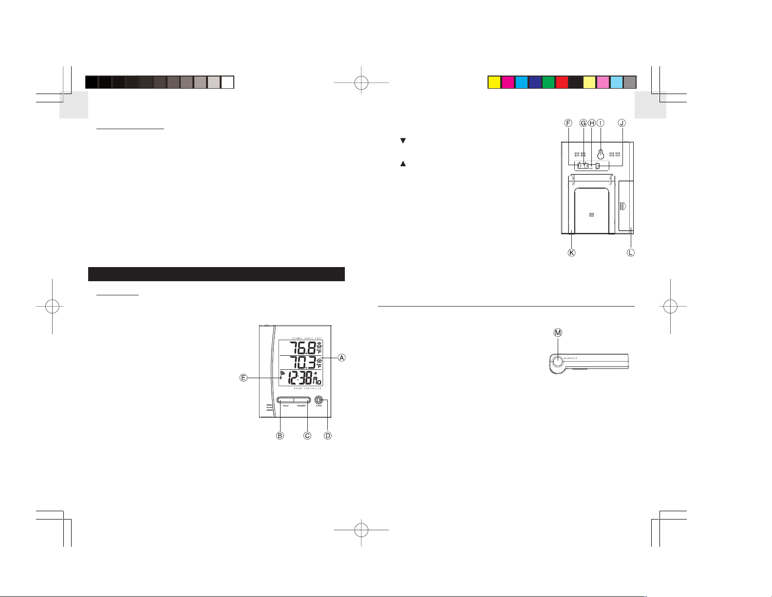
Front View
A. LCD Status Display
The three-line LCD Status Display
facilitates easy readings of the remote and
indoor temperatures, as well as
the calendar clock.
B. MODE Button
Toggles the display modes and confirms
values set as shown on the display.
C. MEMORY Button
Recalls the maximum or minimum
temperature of main or remote unit.
D. ALARM Button
Toggles between Weekday Alarm, Single Alarm,
and Clock Mode.
E. Radio Reception Signal
Indicates the strength of radio reception.
Back View
(Down) Button
F.
Decreases the value of a setting
(Up) Button
G.
Increases the value of a setting.
H. RESET Hole
Returns all settings to default values.
I. Wall-Mount Recess Hole
For mounting the main unit on a wall.
°C/°F Button
J.
Selects temperature display between degrees
Fahrenheit (°F) or Centigrade (°C).
K. Table Stand
For standing the main unit on a flat surface.
L. Battery Compartment
Accommodates two UM-3 or AA -sized 1.5V
batteries.
Side View
M. SNOOZE Button
Activates the snooze function
when an alarm is ringing.
GB
4 5
EMR898_GB(02/05) 12/1/03, 10:36 AMPage 6-7 Adobe PageMaker 6.5C/PPC
Page 5
GB
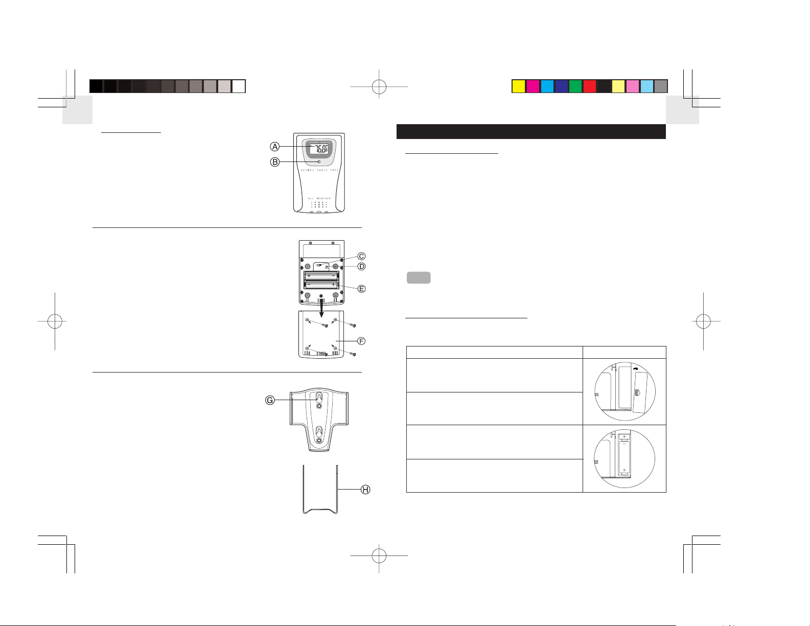
REMOTE UNIT
Front View
A. LCD Status Display
Displays the current temperature
measured by the remote unit.
B. LED Indicator
Flashes when the remote unit transmits
a reading.
Back View
°C/°F Slide Switch
C.
Selects temperature display between
degrees Fahrenheit (°F) or Centigrade (°C).
D. RESET hole
Returns all settings to default values.
E. Battery compartment
Accommodates two UM-3 or AA -sized 1.5V
batteries.
F. Battery Door
Remote Unit Accessories
G. Wall-Mount Holder
Supports the remote unit when
mounted on the wall.
H. Removable Table Stand
For standing the remote unit on a flat surface.
GETTING STARTED
PACKAGE CONTENTS
When you unpack this product, make sure to keep all the packing
materials in a safe place, in case you need to later transport the device
or return it for servicing.
In the box, you will find:
¥ EMR898A unit ¥ Quick Start Guide
¥ Removable table stand ¥ Wall-mount holder
¥ THR268 remote unit ¥ User Manual
When using the product for the first time, the batteries have
already been installed in both the main and remote units.
Locate the clear plastic separator inside the battery
NOTE
compartment. Remove the clear plastic, and close the battery
door. The device will then automatically turn on.
INSTALLING THE BATTERIES
Main Unit
Instructions
1. Locate the battery compartment at the
back of the main unit (→ p.5,L.).
2. Slide the Battery Door to the right.
3. Insert two 1.5V alkaline AA batteries into the
compartment, making sure to align the
polarities correctly as shown by the diagram.
4. Place the Battery Door back onto the
Battery Compartment.
Diagram
GB
6 7
EMR898_GB(02/05) 12/1/03, 10:36 AMPage 8-9 Adobe PageMaker 6.5C/PPC
Page 6

GB
Remote Unit
1. Locate the battery compartment at the back of the remote
unit (→ p.6,E.).
2. Remove the screws on the battery compartment using a
screwdriver (sold separately).
3. Insert two 1.5V alkaline AA batteries into the compartment, making
sure to align the polarities correctly as shown by the diagram.
PLACEMENT OF UNITS
Position the remote unit and the main unit within the effective
transmission range of 20 to 30 meters (65 to 100 feet). The
NOTE
effective range is greatly affected by building materials and
where the units are positioned. Try various setups for the
best result.
Main Unit
You can either mount the main unit on a wall or make it stand on a flat
surface.
GB
4. Replace the Battery Door onto the Battery Compartment and
secure the screws.
UNIT CALIBRATION & RESET
Before you use this product, you must calibrate the unit to synchronize
the transmission and reception of signals. It can also be used to reset
all the functions of the unit to default settings, or in the case of
discrepancies between the units values.
1. Place the remote unit next to the main unit.
2. Using a blunt stylus, press and hold the RESET Hole located at
the back of the main unit (→ p.5,H.).
3. The main unit searches for remote signals soon after the reset. Typically
the device will take up to four minutes to receive the signals.
8 9
Method
Table Stand
Wall Mount
Instruction
The main unit is already equipped
with a pull-out Table Stand which
can support the unit on a flat
surface (→ p.5,K.). Simply pull out
the Table Stand and rest the main
unit on the surface.
The main unit can be mounted
onto a wall using a No. 6 screw
(3.0mm).
a) Position and nail the screw
into the place where you would
like to hang your main unit.
b) Leave ample space between
the wall and the screw head
while testing to make sure the
nail is secure.
c) Fit the Wall-Mount Recess
Hole (→ p.5,I.) of the main unit
onto the screw head.
Diagram
EMR898_GB(02/05) 12/1/03, 10:36 AMPage 10-11 Adobe PageMaker 6.5C/PPC
Page 7

GB
Remote Unit
Similarly, you can choose to either mount the remote unit on a wall or
make it stand on a flat surface.
It is recommended to place the unit away from direct sunlight, rain,
NOTE
and snow.
Method
Table Stand
Instruction
The remote unit can be outfitted
Diagram
with the Removable Table Stand
(→ p.6,H.).
Wall
Mount
Use no.6 screws with the
Wall-Mount Holder and fit
the remote unit onto the
holder (→ p.6,G).
LCD DISPLAY
A. Remote Temperature
Displays the temperature
measured by the remote unit
(in either °F or °C).
B. Indoor Temperature
Displays the temperature
measured by the main unit
(in either °F or °C).
C. Radio Reception Display
Shows the status of clock
synchronization with the U.S.
Atomic Clock.
D. Kinetic Wave Display
Shows the receiving status of
temperature readings from
the remote unit.
E. Current Time
Shows current time (in 12-hour or 24-hour mode).
F. Current Weekday
Shows the current weekday.
GB
F
NOTE
To switch the LCD display s temperature unit between
Fahrenheit and Centigrade, press the
°F/°C Button.
MAIN UNIT TEMPERATURE READINGS
Once the batteries are installed and the main and remote units are
calibrated and set in place, the main unit will start reading
temperatures.
10 11
EMR898_GB(02/05) 12/1/03, 10:36 AMPage 12-13 Adobe PageMaker 6.5C/PPC
INDOOR TEMPERATURE READINGS
The main unit also reads the temperature of its own surroundings. It displays
this temperature on the second line of the LCD display (→ p.11,B.). This
second reading is updated approximately every 78 seconds.
LCD Display Description
Soon after the batteries have been installed, the main
unit immediately reads and displays the surrounding
temperature on the second line of the LCD screen.
Page 8

GB
REMOTE TEMPERATURE READINGS
The remote temperature readings are displayed on the top line of the
LCD screen display (→ p.11,A.).
LCD Display Description
Soon after the batteries have been installed, the
main unit searches for signals from the remote unit.
This process takes about 4 minutes.
Upon successful reception, the remote unit
temperature is displayed on the top line of the
LCD (→ p.11.A.).
If no signals are received from the remote unit, the
top temperature remains blank and the unit stops
searching. To force the main unit to search once
again, use a blunt stylus to press the RESET Hole
located at the back (→ p.11,A.).
Kinetic Wave Display
The Kinetic Wave Display is only shown on the top line of the main
unit. It displays the current receiving signal status from the remote
unit to the main unit. The display is shown in three different forms:
LCD Display DescriptionSignal
Blinking signal
The main unit is searching for
signals from the remote unit.
Radiating signal
Temperature readings from
the remote unit are securely
registered.
No signal
No signals received from the
remote unit. Searching has
stopped.
12 13
TEMPERATURE RANGE
This product is designed to work under the widest temperature ranges
possible. However, if the temperature falls above or below the device s
operation range, the display will change to the following:
LCD Display Description
When the LCD screen displays HHH , the
temperature is above the measuring range of the
remote or main unit (see Specifications → p.24 ).
When the screen displays LLL , the temperature
is below the measuring range of the remote or
main unit (see Specifications → p.24 ).
MAXIMUM / MINIMUM TEMPERATURES
Displaying Maximum / Minimum Temperatures
The maximum and minimum indoor and remote temperatures
recorded are automatically stored in memory. To display them, follow
the instructions below:
1. Current remote and indoor
temperatures displayed.
Press MEMORY
2. Maximum temperatures recorded
Press
MEMORY
Press MEMORY
are shown for both remote and
indoor temperatures.
3. Minimum temperatures recorded
are shown for both displays.
shown for both remote and indoor
temperatures.
GB
EMR898_GB(02/05) 12/1/03, 10:36 AMPage 14-15 Adobe PageMaker 6.5C/PPC
Page 9

GB
Resetting Maximum / Minimum Temperatures
To clear the maximum and minimum recorded temperatures:
Radio Reception
GB
Description
Strong reception of the U.S. Atomic Clock signal.
1. Press and hold MEMORY for 2 seconds.
The maximum and minimum temperatures
Press MEMORY
for both indoor and remote readings will be
erased.
2. The maximum and minimum temperatures
Press MEMORY
will have the same values as the current
temperature until different readings are
recorded.
CLOCK FUNCTIONS
Your product is designed to synchronize its calendar clock
automatically once it is brought within range of the radio signal from
the U.S. Atomic Clock. When the main unit is new and just out of the
box, synchronization with the U.S. Atomic Clock can take up to 72
hours. When the unit is receiving the signal, the Radio Reception
symbol with start to blink. Generally, complete reception takes around
2 to 10 minutes, depending on the strength of the radio signal. The
clock automatically searches for radio signal at 1AM, 2AM, 3AM,
9AM, 3PM and 7PM daily.
Weak reception of the U.S. Atomic Clock signal.
No reception of the U.S. Atomic Clock signal.
Receiving the U.S. Atomic Clock signal.
Radio Reception is disabled.
Reception can be affected by a number of factors. For best
reception, place the device away from metal objects and
electrical appliances. Other causes for signal interference
NOTE
include electrical transmission towers, steel reinforced
construction, and metal siding. Reception is ideal when placed
near a window.
Even though there are areas that may have more difficulty in
NOTE
receiving a signal, the Atomic Clock contains accurate quartz
movement and will retain precise timing even if the signal is
occasionally missed.
ENABLING / DISABLING RADIO RECEPTION
To manually disable the reception of the Radio Frequency (RF) signal,
press and hold
(→ p.4,C.) for 2 seconds until the Radio Reception
symbol completely disappears.
To enable the reception again, press and hold
(→ p.4,C.) for 2
seconds. The Radio Reception symbol will blink and the unit will search
for the RF signal automatically.
14 15
EMR898_GB(02/05) 12/1/03, 10:36 AMPage 16-17 Adobe PageMaker 6.5C/PPC
Page 10

GB
LANGUAGE OPTIONS
The main unit can display the weekday in
Symbol
Language
English
five different selectable languages. Refer
Setting the Time and Language
to
German
Displays for instructions on changing the
language (→ p.18).
French
Italian
Spanish
TIME ZONE OPTIONS
Time zones around the world are identified by how many hours they
are offset from the Greenwich Mean Time (GMT). US time zones are
5 to 10 hours behind the Greenwich Mean Time. The main unit is preset to Pacific Standard Time (PST). Adjust the GMT Difference
according to which time zone you live in order to obtain accurate time
from the U.S. Atomic Clock (→ p.18).
The U.S. Atomic Clock automatically adjusts for Daylight
NOTE
Savings during the year. However, if Daylight Savings is not
applicable in your area, you may instead want to manually
set the time and disable the U.S. Atomic Clock (→ p.18).
Name
Eastern
Standard Time
(EST)
Central
Standard Time
(CST)
Mountain
Standard Time
(MST)
Pacific
Standard Time
(PST)
Alaska
Standard Time
(AKST)
Hawaii
Standard Time
(HST)
GMT
States
Difference
-5 Hours
Michigan, Georgia, West Virginia,
Ohio, Virginia, Connecticut, Vermont,
Rhode Island, Massachusetts,
Maine, New York, New Jersey,
Delaware, New Hampshire,
Washington D.C., Pennsylvania,
Maryland, Florida*, Kentucky*,
Indiana**
-6 Hours
Illinois, Louisiana, Alabama,
Mississippi, Oklahoma, Iowa,
Arkansas, Minnesota, Wisconsin,
Missouri, Texas*, Kansas*,
Tennessee*, South Dakota*, North
Dakota*, Nebraska*
-7 Hours Colorado, Utah, Wyoming, New
Mexico, Arkansas, Montana*, Idaho*
-8 Hours
Washington, California, Nevada,
Arizona**, Oregon*
-9 Hours
-10 Hours
Alaska
Hawaii**
GB
16
EMR898_GB(02/05) 12/1/03, 10:36 AMPage 18-19 Adobe PageMaker 6.5C/PPC
17
Page 11

GB
* These states have certain parts where a different time zone is
followed. Check to make sure to set the correct time zone for your
area.
** These states have certain areas where Daylight Savings are not
observed. In Hawaii, the whole state does not follow Daylight Savings.
SETTING THE TIME AND LANGUAGE DISPLAYS
Your clock is designed to automatically set itself using the radio signal
from the U.S. Atomic Clock. However, should you need to manually
set the clock without using the radio signal, follow the instructions
below. You can also choose your language for the weekday display
here.
GB
1. Press and hold MODE for 2 seconds.
Press MEMORY
2. Adjust the GMT difference according to
your timezone.
Press MEMORY
3. Choose between 12-hour or 24-hour
time formats.
Press MEMORY
4. Adjust the current hour.
Press
NOTE
to normal clock mode, press the ALARM button anytime
or to adjust the values for each setting. To return
during the procedures below.
We recommended that you disable the RF signal before
NOTE
manually setting the clock (→ p.15).
Press MEMORY
5. Adjust the current minute.
Press MEMORY
6. Adjust the current year.
Press MEMORY
7. Adjust the current month.
Press MEMORY
8. Adjust the current date.
Press MEMORY
9. Choose the language for the day
of the week displayed.
Press MEMORY
10. Return to normal clock operation.
18 19
EMR898_GB(02/05) 12/1/03, 10:36 AMPage 20-21 Adobe PageMaker 6.5C/PPC
Page 12

GB
ALARM FUNCTIONS
The unit is equipped with 2 alarms: Weekday Alarm
Icon Type Description
Weekday
Alarm
The Weekday Alarm will sound Monday to Friday
at the preset time. It is automatically disabled
during weekends (Saturdays and Sundays).
Single
Alarm
The Single Alarm sounds only once according to
the preset time.
Activating / De-activating the Alarms
1. Press ALARM. The clock will enter
Weekday Alarm setting.
Alarm Off
2. Press
Weekday Alarm on or off.
Alarm On
3. Press ALARM. The clock will enter
Single Alarm setting.
Alarm Off
4. Press
Single Alarm on or off.
and Single Alarm.
or to toggle the
or to toggle the
To return to normal clock mode, press the MODE button
NOTE
anytime during the procedures below.
Setting the Alarms
Press
or to adjust the values for each setting. To return
to normal clock mode, press the MODE button anytime during
NOTE
the procedures below.
Press & hold
ALARM for 2 seconds
Press MEMORY
Press MEMORY
Press & hold
ALARM for 2 seconds
Press MEMORY
Press MEMORY
GB
1. Press ALARM to enter Weekday
Alarm setting.
2. Adjust the Weekday Alarm s hour
setting.
3. Adjust the Weekday Alarm s minute
setting.
4. Press ALARM to enter Single Alarm
setting
5. Adjust the Single Alarm s hour
setting.
6. Adjust the Single Alarm s
minute setting.
7. Press ALARM to return to
normal clock operation.
Alarm On
5. Press ALARM to return to normal
clock operation.
Crescendo Alarm
When the alarm goes off at the preset time, the Alarm Icon (
flashes and the alarm audibly rings. The alarm sound gradually increases in
volume and intensity for 2 minutes.
20 21
EMR898_GB(02/05) 12/1/03, 10:36 AMPage 22-23 Adobe PageMaker 6.5C/PPC
or ) then
Page 13

GB
Press SNOOZE (→ p.5,M.) to temporarily stop the alarm. The alarm
will sound again after 8 minutes unless another key on the clock is
pressed. To stop the ringing completely, press ALARM.
The Single Alarm will automatically disable itself after the
NOTE
clock has gone off at the preset time. The Weekday Alarm
will still be enabled even after the alarm has gone off.
OTHER FEATURES
LOW BATTERY WARNING
When the battery is low, a battery icon will appear on the main unit s
LCD screen.
LCD Display Description
When the indicator appears on the top line of the
LCD screen, the remote unit battery is low.
When the indicator appears on the bottom line of
the LCD screen, the main unit battery is low.
TROUBLESHOOTING
This section includes a list of frequently asked questions for problems
you may encounter. If your device is not operating as you think it
should, check here before arranging for servicing.
Problem Symptom Check This Remedy
displayed on
LCD screen.
The remote
signal
cannot be
received.
Obstacles (either
electromagnetic
interference or
objects) are
barring the
remote signal
from reaching
the main unit.
Move the main
unit away from
any sources of
interference,
including other
electronic
devices. Also
try moving the
remote and the
main units
closer.
Discrepancies
between
remote and
main unit
readings.
Batteries of
the remote
unit are low.
Another
remote
sensor is
using the
same
frequency
Check LCD
Display of the
remote unit.
Check if another
remote sensor is
present within the
area.
Install new
batteries into
the remote unit.
Place the remote
sensor closer to
the main unit.
Recalibrate the
units to ensure
synchronization.
and ID Code.
Measurement
does not
seem
accurate.
Displayed
temperature
data are
different
from other
measuring
instruments.
The measurement
method is
different.
The areas under
evaluation are
different or are
influenced by
climate.
The temperature
resolution for
different
products may
also be different.
Place the 2
instruments very
closely for a time
period (no less
than 30 minutes),
avoiding direct
light and air
movements.
GB
22
EMR898_GB(02/05) 12/1/03, 10:36 AMPage 24-25 Adobe PageMaker 6.5C/PPC
23
Page 14

GB
Problem Symptom Check This Remedy
Clock time is
not correctly
set.
No radio
signal
reception.
The areas under
evaluation are
different or are
influenced by
climate.
Electromagnetic
interference or
objects are
barring reception.
Orientation or
placement of
main unit is not
optimum for
receiving U.S.
Atomic Clock
signal.
No Alarm
Operation
Not Normal
Alarm does
not sound.
Certain
functions do
not perform.
Alarm is disabled.
Device requires
reset.
Turn on the
alarm setting.
Reset the unit
with a blunt stylus
pressed against
the RESET Hole.
SPECIFICATIONS
Main Unit
Type
Indoor Temperature
Operation Range
Temperature Resolution 0.2ßF (0.1ßC)
Power 2 x UM-3 or AA 1.5V batteries
Weight (without battery) 5.01 Oz. (142g)
Description
23.0ßF to 122.0ßF
(-5.0ßC to +50.0ßC)
Remote Unit
Type
Temperature Operation Range
Description
-4ßF to 140ßF (-20.0ßC to +60.0ßC)
Temperature Resolution 0.2ßF (0.1ßC)
RF Transmission Frequency 433 MHz
RF Transmission Range Maximum 100 feet (30 meters)
Temperature Sensing Cycle 78 seconds
Power 2 x UM-3 or AA 1.5V batteries
Weight (without battery) 2.84 Oz. (80.5g)
Dimension 4.13 x 2.76 x 0.83 inches (L x W x H)
105 x 70 x 21 mm (L x W x H)
ABOUT OREGON SCIENTIFIC
Visit our website (www.oregonscientific.com) to learn more about your
device and other Oregon Scientific products such as hand-held
organizers, alarm clocks, and weather stations. The website also
includes contact information for our customer service department, in
case you need to reach us.
'2003 Oregon Scientific. All rights reserved.
GB
Dimension
4.72 x 3.63 x 0.95 inches (L x W x H)
120 x 93 x 24 mm (L x W x H)
2524
EMR898_GB(02/05) 12/1/03, 10:36 AMPage 26-27 Adobe PageMaker 6.5C/PPC
 Loading...