

Page 1
Increase Quality Through Interaction with the Field
The Oreck Manufacturing Company
Compiled by Clark DeNoble
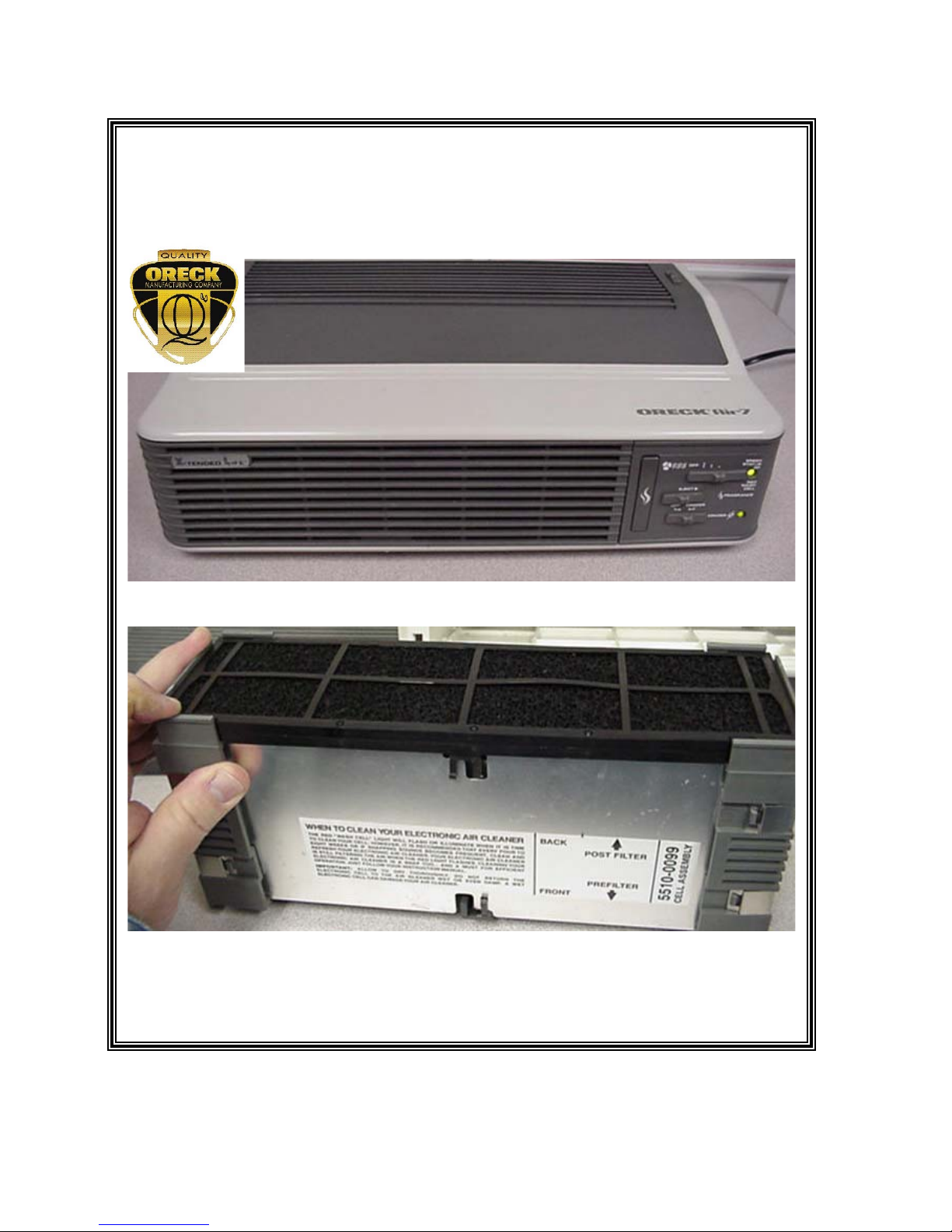
8143 Air Purifier Tune-Up & Service Guide
07/20/2005
Increase Quality Through Interaction with the Field
1
Page 2
Increase Quality Through Interaction with the Field
Table of Contents
Tune-Up Pages 3-13
Check Housing Aesthetics and Structural Integrity Page 3
If Equipped: Check that the Louver Functions Smoothly Page 3
Check Fan Speed Switch and Motor Function Pages 3-4
Check the Status Light Function Pages 4-6
If Equipped: Check the Ionizer Switch Function Page 6
Check For Unusual Noises Pages 6-10
Thorough Washing Instruction Pages 8-10
If Equipped: Check Scent Cartridge Holder Function Page 10
Check the Safety Interlock Switch Function Page 10
Check the Structural Integrity of the Cell Pages 10-11
Clean Pages 11-12
Finishing Up Pages 12-13
Other Troubleshooting & Service Pages 13-21
Status Light Dead Pages 6
Nothing Works Pages 13-14
Lights Work Motor Doesn’t Pages 14-15
Remove and Replace Motor Pages 15-19
Cell High Voltage Circuit Board Replacement Pages 9-20
Circuit Diagram (10/20/03) Page 21
If the conditions are dry
enough even a cell this dirty
may not set off the red status
LED continuously.
Increase Quality Through Interaction with the Field
2
Page 3
Increase Quality Through Interaction with the Field
Tune-Up
1. Check Housing Aesthetics and Structural Integrity
a. If you cannot see the blemish at arms length then it probably doesn’t matter
otherwise apply the following.
b. Hairline scratches:
i. Top & Sides-no more than 2, at ≤ ½”, on each surface.
ii. Rear & Bottom-no more than 3, at ≤ 1”, on each surface.
c. Gouges:
i. Top & Sides-none
ii. Rear & Bottom-no more than 2, at ≤ ¼”, on each surface.
d. Cracks:
i. No more than 2 total, at ≤ ¼”, per unit.
2. If Equipped: Check that the Louver Functions Smoothly
a. Operate the actuator back and forth.
b. Assure the louvers all move together at the same time.
3. Check the Fan Speed Switch and Motor Functions
a. Must function in all three positions.
b. Test whether the fan will bind in Silent. Unplug the unit and set the switch to silent.
Plug in the unit-the fan should start up.
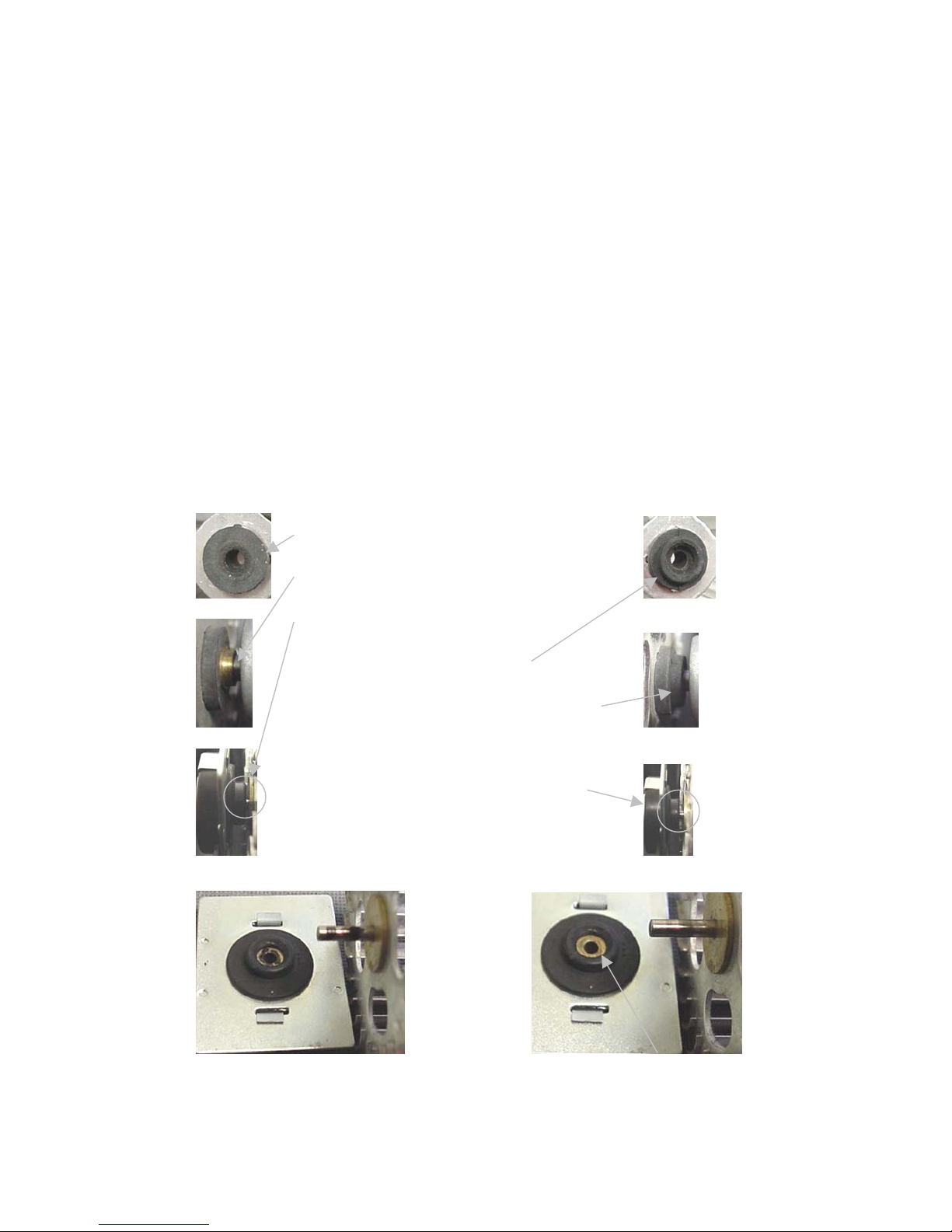
c. If it doesn’t, first check for proper fan installation:
The fan grommet on the left is solid, has four
holding tabs, butts against the motor shaft’s
brass ring and must hold in this position to
provide clearance between the fan and fan
bushing grommet. This fan grommet must be
a tight fit to the motor shaft and free of
lubricants.
The grommet on the right is tiered, has four
holding tabs and envelops and holds onto the
motor shaft’s brass ring. As you can see if
this grommet is only butted against the brass
ring then the normal clearance between the
fan and fan bushing grommet shown in the
picture would be nonexistent. The reduced
clearance could cause screeching as the
d. Then check to see if the fan shaft and bearing are gummed up or worn:
Clean fan shaft and bearing. Apply oil to bearing assembly.
Increase Quality Through Interaction with the Field
3
Page 4

Increase Quality Through Interaction with the Field
FYI-There is a felt behind the bearing. When you apply oil to the bearing hole
allow time for it to soak into the felt.
Fan Bearing
Assembly-
Front
Bearing Assembly Bracket
4. Check Status OK Light Function
a. Changes from red to green when the unit is turned ON.
b. If it stays RED then remove the cell, activate the unit.
c. If the light turns green then the cell was the problem (Red Status Light Due to Cell-
Additional).
d. If the light stays red then either the circuit area is wet, poor electrical contact between
the cell and HV contacts or HV assembly is defective.
Felt Retainer
Oil Retention
Felt
You’ve washed, rinsed and dried the cell and the
Status light was still red.
1. Remove the cell and power up the unit. If the
Status light goes green then proceed to step
2.
Note: If the Status light stays red see 4c.
2. Carefully pry up and remove the front plate
support bar and return cell to unit.
Note: Be sure to remember how the bar was
positioned on the cell plates.
3. If the Status light turns green then skip to step 9.
4. If the Status light turns red go to step 5.
Increase Quality Through Interaction with the Field
5. Carefully pry up and remove the rear plate
support bar and return cell to unit.
Note: Be sure to remember how the bar was
positioned on the cell plates.
6. If the Status light turns green then remove
the cell from the unit and reinstall the first
support bar.
7. If the Status light stays green then that
support bar is good.
8. If the Status light turns red then remove the
support bar and proceed to step 9.
4
Page 5
Increase Quality Through Interaction with the Field
9. Take the bar/s and look for a carbon trail light
to dark brown or just discolored (circled).
This trail is often hard to see but it is
supplying an electrical path from a negative
plate to a positive plate (see arrows). This
electrical connection causes the Status light
to turn red.
10. Scrap off the carbon trail on one bar, reinstall
and test. If the Status light stays red then
remove the bar and scrap some more.
11. If the Status light turns green then go to work
on the other bar (if there is one) and repeat
step 10.
e. Some cells deeply burned/hidden carbon trails that cannot be scraped off or corona
wires that were stretched or broken. Replace the cell.
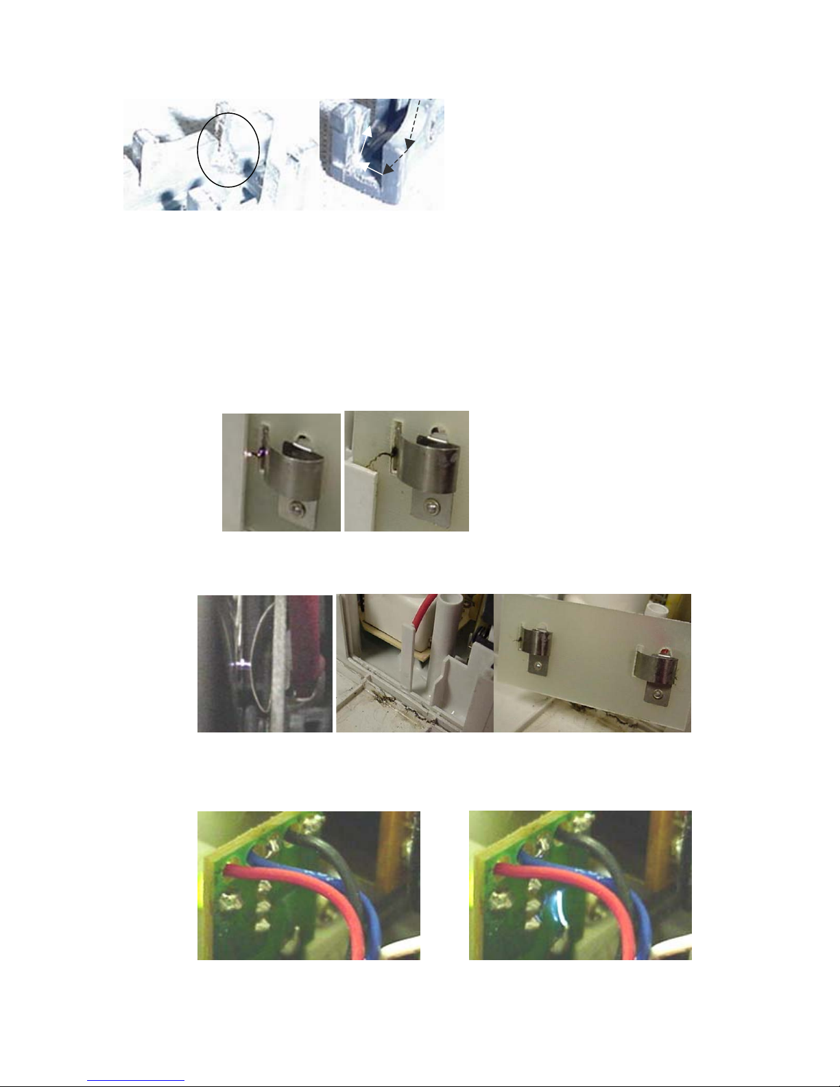
f. Red Light due to arcing or carbon trails at the cell contact board.
Picture 1 shows the arc in progress.
Picture 2 shows the carbon trail formed by the arc. The carbon trail makes later
failure much easier, scratch it off.
g. If with the cell in, the status light constantly changes from green to red and back:
Either the HV conductor is not making good contact with the cell. Bending it out
usually does the trick.
Dry the slot and cell contact board before buying a new HV circuit
board (See pictures on page 19)
or
h. There is arcing on the LED board due to post ionizer reaction with residue on the
housing. (See Thorough Washing Instruction).
Increase Quality Through Interaction with the Field
5
Page 6
Increase Quality Through Interaction with the Field
i. Status light function reversed:
Operates in reverse, when you turn the unit ON the Status light briefly shows green
then goes to red and when you turn the unit OFF the Status light fades from red to
green and goes out, then either the wiring is reversed or the LED board is defective.
j. Status light never comes on:
If the Status light doesn't light at all then either the LED board, transformer or HV
circuit board is defective (See Status Light Dead).
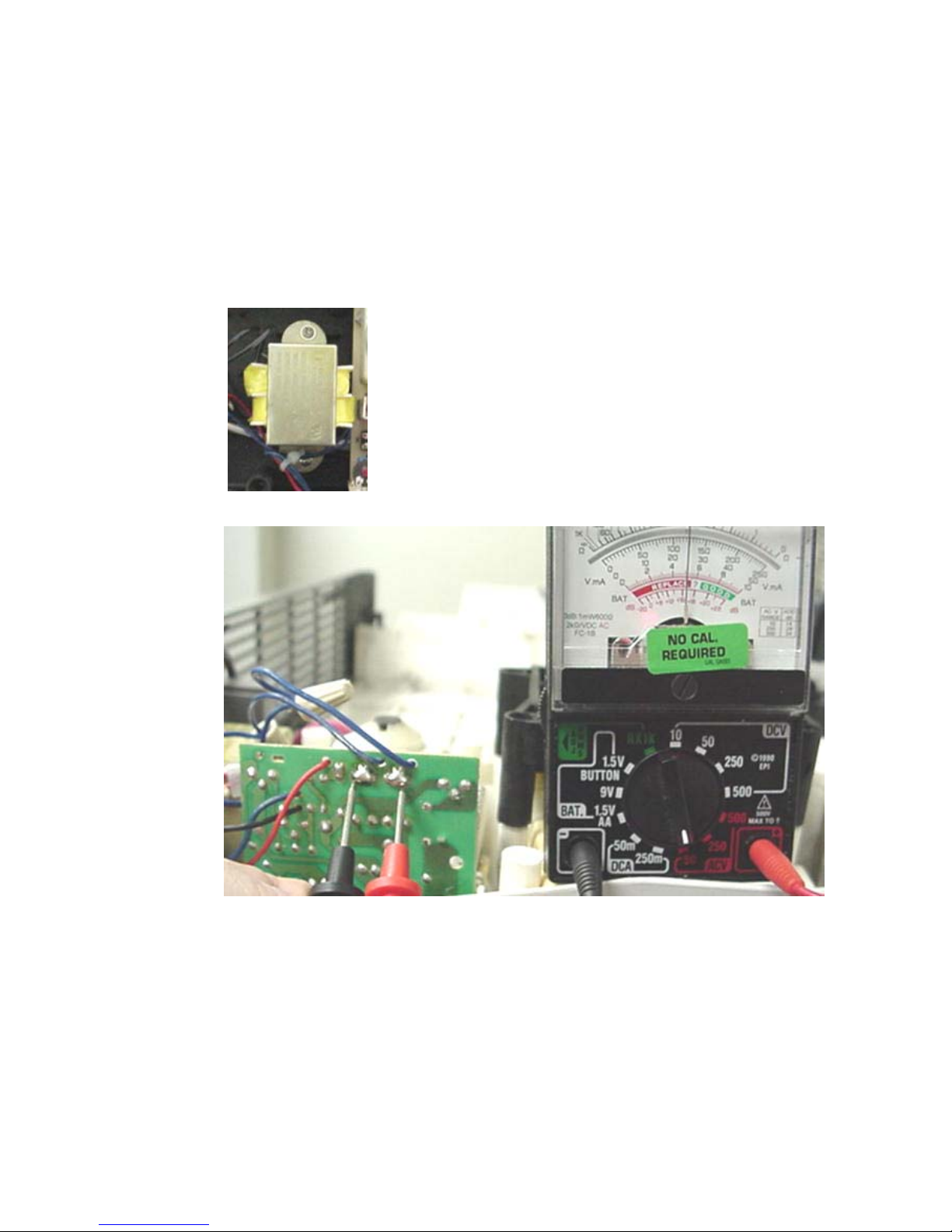
Status Light Dead
There may be a problem with the yellow step down transformer.
If the transformer passes this check then the problem is the LED board or the
whole LED HV circuit board assembly.
Select the 50 VAC scale on your Multimeter. Turn the unit ON.
Touch the meter leads to the two solder joints shown below. A good transformer will
put out 24VAC.
If you don’t see 24VAC, turn the unit OFF and scrape the solder joints to remove any
coating. Turn the unit ON and test again. If you still don’t measure 24VAC then the
transformer needs to be replaced
Important: If the transformer is bad the power to the cell will also
be OFF. Replace the bad transformer first and test before ordering
the LED or HV boards.
5. If Equipped: Check the Ionizer Switch Function
6. Check for Unusual Noises
a. Ticking
i. Unbalanced Fan-shaft tapping the brass bearing-). If you see a significant up
and down movement this may be the problem (replace the fan unless
twisted. (See Twisted Fan 6 a iv).
ii. Dry Felt/Bearing-no oil
iii. Cocked Bearing-straighten
Increase Quality Through Interaction with the Field
6
Page 7

Increase Quality Through Interaction with the Field
iv. Twisted Fan- Determine if the fan is twisted (the blades should be
horizontal). You can untwist the fan by gently turning the ends so the blades
straighten out (this has eliminated ticking
v. Bent Fan-some service fans get bowed from either shipping damage or
mishandling-replace the fan
vi. Dry Motor Ball Bearings
There are a couple of ways to determine if it's the motor bearing:
• Take a long shaft screwdriver, put the blade against the bearing
housing then put your ear against the handle and listen.
• Remove the fan and hear if the noise continues.
Indicators
• No noise (the bearing is packed (greased) well and probably on
a new unit).
• Some very sporadic non-rhythmic bearing ticking only heard
using the screwdriver (normal).
• Then there's the “shaking ball bearings in a cup” noise (bearing
is dry-this is probably the condition that gives you the noise of
concern).
• Finally, f it sounds like gravel then the bearings are already
damaged.
Although not recommended, if you choose to repack the bearings, use hightemperature grease, not automotive axle (stinky) grease.
b. Snapping behind the switch panel. Arcing at the LED board (may or may not cause
the Status light to flicker.
If the arcing stops when the ionizer is turned off then it is always due to
residue/moisture in the cell/fan portion of the housing including the ionizer needle
and bracket. This will require a thorough washing.
Increase Quality Through Interaction with the Field
7
Page 8

Increase Quality Through Interaction with the Field
THOROUGH WASHING INSTRUCTION
1. REMOVE UPPER HOUSING
Turn the unit onto its’ backside.
Remove 9 screws.
2. REMOVE UPPER HOUSING
Tilt the upper housing off the lower
housing.
You may need to hold the fan- bushing
bracket down while removing the upper
housing.
Remove the fan and bracket.
3. REMOVE THE SAFETY INTERLOCK SWITCH
Loosen the switch panel from the
housing.
Push in the safety interlock switch
button and pull out the switch.
Disconnect the power cord connector
from the switch terminal.
4. FREE THE POWER CORD NEUTRAL LEAD
Find the wire butt connector that
secures five (5) wires together.
Often you can squeeze the connector
and release the wires otherwise you’ll
need to cut the connector as shown
and pull it off the wires.
5. REMOVE THE TRANSFORMER
Increase Quality Through Interaction with the Field
Remove the two (2) screws that
fasten down the transformer
.
8
Page 9

Increase Quality Through Interaction with the Field
6. REMOVE THE POWER SUPPLY
Remove the two (2) screws that fasten down the
power supply.
7. REMOVE THE MOTOR HOLD DOWN BRACKET
Remove the four (4) screws from the bracket.
Remove the bracket.
Remove the two (2) upper motor mounts
8. REMOVE THE IONIZER NEEDLE AND BRACKET
Remove one (1) screw from the ionizer needle bracket.
Remove the needle and bracket.
9. REMOVE THE IONIZER POWER SUPPLY AND MOTOR
10. REMOVE THE LOWER MOTOR MOUNTS
Increase Quality Through Interaction with the Field
Remove one (1) screw from the ionizer power
supply.
Gently remove the switch panel, transformer, power
supply, motor and ionizer power supply with needle
from the lower housing.
9
Page 10

Increase Quality Through Interaction with the Field
11. REMOVE THE POWER CORD
Remove two (2) screws.
Remove the cord clamp.
Remove the cord.
12. CLEAN AND REASSEMBLE
CAUTION DO NOT USE:
Solvent Spot & Stain Remover: liquefies the plastic.
1. Cleaning may involve just rinsing the
housings, fan and cell parts with hot water.
2. If a cleanser is used be sure to thoroughly
rinse with water (excessive residue may
cause arcing on the LED board.
3. The cell must be thoroughly dried or the
Status light will stay red and the cell plastic
might be burned.
4. Reassemble the unit starting with M in reverse
order.
5. At step 4
a. Strip the five (5) leads to expose ≈
½” of bare metal.
b. Twist the exposed wires together
clockwise (important if using a wire
nut).
c. Crimp on a wire but (shown) or twist
on a wire nut. Check that all the
wires are securely captured.
6. Tie the three (3) bundles together.
c. Rumbling
i. Worn fan grommet
ii. Unbalanced fan – remove fan if noise goes away it’s the fan
iii. Unbalanced motor – remove the fan if the noise continues it’s the motor
iv. Unit on an uneven surface
d. Screeching/Seal Bark
i. The fan is rubbing against the rubber fan bearing
7. If Equipped: Check the Scent Cartridge Holder Function
8. Check the Safety Interlock Function and Begin Cleaning Process
a. Leave the unit turned on, loosen the grill retainer screw, push in the actuator and
remove the grill-the unit should turn off.
b. If it doesn’t, replace the interlock switch.
c. Place the grill and place in a soap bath. Gently clean, rinse and dry.
Increase Quality Through Interaction with the Field
10
Page 11

Increase Quality Through Interaction with the Field
9. Check the Structural Integrity of the Cell
a. Remove the cell from the unit
b. Remove the Pre-filter from the Precipitator cell and place in a soap bath. Gently
clean, rinse and dry.
c. Remove Odor (Carbon) Absorber and discard.
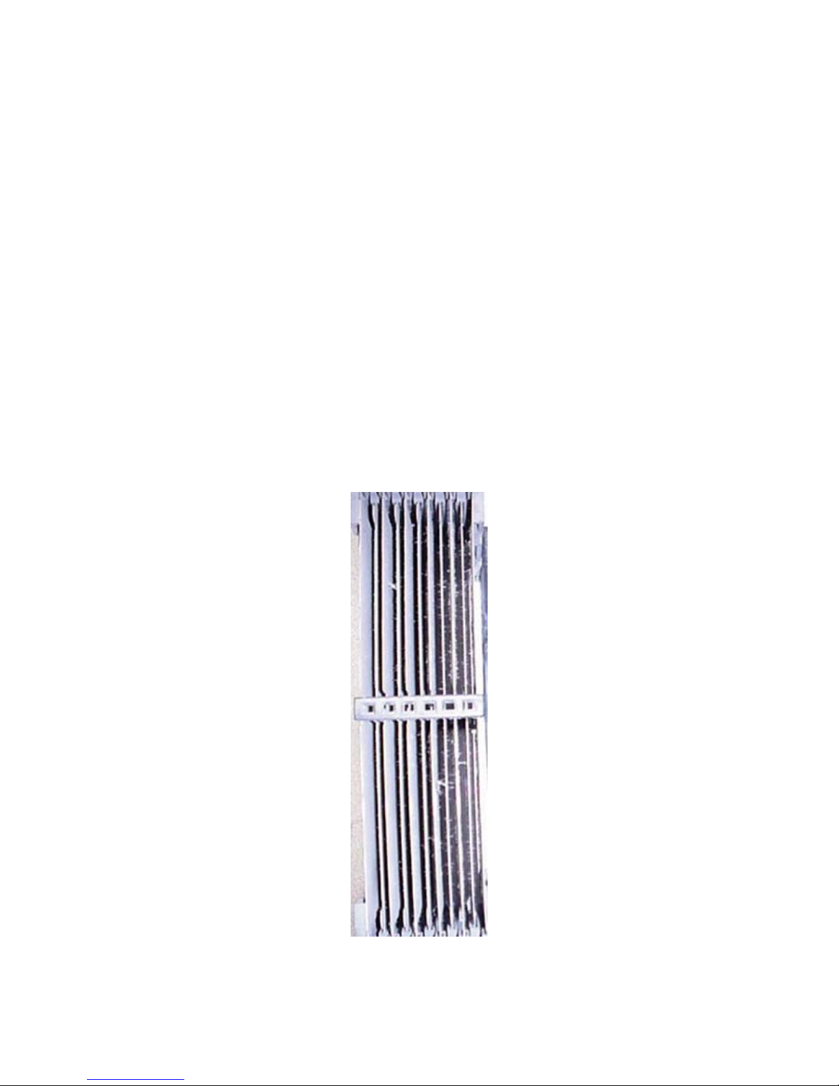
d. Pre-charge wires should be stretched tight (may have a slight wavy look if it doesn’t
cause arcing)
e. Plates should be flat and evenly spaced
f. End Cards and spacers should be free of burns and distortions.
g. Discard the precipitator cell if pre-charge wires are broken or plates are bent beyond
reasonable repair or end cards/spacers are burnt beyond repair.
Pre-charge wires
Spacer
End Card
e. Wash out the precipitator cell and fan. Gently clean with Assail-A-Cell or other
10. Clean
Skip the Thorough Washing Instruction (See 6b) and go to step g if the unit doesn’t
require a thorough washing.
Use a vacuum cleaner to remove dust and debris from the Precipitator Cell cavity, fan,
louvers and exhaust grill.
recommended cleanser, rinse with fresh water and dry.
Increase Quality Through Interaction with the Field
11
Page 12

Increase Quality Through Interaction with the Field
Gently clean the two metal contacts of the cell interconnect board with a plastic safe
contact cleaner/lubricant and soft cloth.
Use Zoom Spout or equivalent to lubricate the fan bearing.
11. Finishing Up
• Cell High Voltage function can be verified. Method can be performed with or without
the top cover installed. Safety First-If performed without the top cover installed
remove the fan.
• Neon Bulb Circuit Tester: Caution-the condition is a static charge. Manage the tester
lead so you don’t have to hold the tester. Touch the front cell contact with one leg of
the inexpensive circuit tester shown in Figure A1. Leave the other leg dangling. Turn
the unit on and enable the safety switch as shown in A2. If the neon bulb of the tester
doesn’t light up then the HV Power Supply is defective.
Fix tester lead to this
contact point.
A1 A2
• Negative HV Power Supply Test-Ionizer Generator function can be verified. Safety
First – Remove top cover and fan.
• Caution-the condition is a static charge. Manage the lead so you don’t have to hold
the tester.
• Rest the end of the test lead on the ionizer needle.
• Turn the unit ON and insure the IONIZER switch is in the IONIZER position.
• The bulb will glow if the ion generator is working.
Increase Quality Through Interaction with the Field
12
Page 13

Increase Quality Through Interaction with the Field
Located in the fan
chamber on a bracket on
the right side of the back
wall.
Ionizer Needle
Off
• Fit the pre-filter and new odor absorber to the precipitator cell.
• Install the cell.
• Fix the grill in place and tighten the retaining screw.
• Recheck all switch functions for proper unit operation.
• Clean the exterior using Oreck Foam Cleaner 32252 or equivalent. Don’t spray any
cleaning product into louver area (may result in stray static arcing).
Other Service Considerations
Nothing Works
1. Set the Multimeter to Ohms
On
2. Find the unit’s plug. Touch a probe to the large blade and the other to the small blade
(Polarity doesn’t matter here).
3. If the unit is off, you should get an ∞ reading.
Increase Quality Through Interaction with the Field
Touch the test probes together and adjust for a 0 indication.
13
Page 14

Increase Quality Through Interaction with the Field
4. You should get a 0 reading in each of the three On positions.
5. If you get an ∞ (infinite) reading the problem is either with the power switch, wiring including
cord, safety switch or safety switch actuator.
6. Check that the safety switch actuator on the grill (1/8” bump) isn’t missing
7. The actuator activates the switch safety interlock.
Lights Work but the Motor Doesn’t (Added 11/21/03):
1. Unplug the unit from the wall socket.
2. Remove the top cover (9 screws).
3. Turn the fan speed switch to OFF.
4. Touch a meter lead to the Neutral/Larger blade of the plug.
Increase Quality Through Interaction with the Field
14
Page 15

Increase Quality Through Interaction with the Field
5. Touch the other lead to the back of the power switch where the black, (brown or blue) and
red.
6. If you get a ∞ reading in any position then the motor is bad.
7. Check the Interlock/Safety switch by removing the two leads (Fig F).
8. Touch the Multimeter leads to the switch terminals and press in the switch button with a small
blunt object (Fig G). If the meter goes to 0 then the switch is good.
F G
Remove and Replace the Motor
1. Turn the unit over and remove nine (9) screws.
2. Turn the unit back over and carefully remove the top housing.
3. You may need to reach in and pull down the fan assembly if it’s caught in the top housing
(Fig H).
Increase Quality Through Interaction with the Field
15
Page 16

Increase Quality Through Interaction with the Field
4. Lift the fan out of the side shown in Fig H and pull it off the motor shaft (Fig I).
I
5. Remove the four (4) screws securing the motor to the lower housing (Fig J).
J
6. Remove the two (2) upper motor mounts.
7. Remove the ionizer mounting screw.
8. Lift up the ionizer and move it out of the way.
Increase Quality Through Interaction with the Field
16
Page 17

Increase Quality Through Interaction with the Field
9. Turn the defective motor on its’ side and remove the cable clamp screw.
.
10. Cut the four (4) wire leads from the motor. Remove motor.
11. Install the new motor and place the new harness with the old harness.
12. Cut off the excess wire from the new motor to match the total length of the old harness.
Increase Quality Through Interaction with the Field
17
Page 18

Increase Quality Through Interaction with the Field
13. Trim back the jacket (outer covering) for a convenient lead length on both harnesses so you
can strip (3/8”) the wires.
14. For stability cable tie both harnesses together before connecting leads.
15. Connect the leads together: white/white, blue/blue, red/red & black/black.
16. Bend the harnesses to fit under the ionizer generator.
17. Place the ionizer generator over the harnesses and fasten with one screw.
18. Place the motor mounts on the motor.
19. Fit the motor bracket over the motor and fasten with four screws.
Increase Quality Through Interaction with the Field
18
Page 19

Increase Quality Through Interaction with the Field
20. Fit the fan to the motor shaft. One fan grommet is made to butt up against the brass retainer
on the motor shaft and another fits over.
21. Reassemble and test operation: must work in all three “On” positions.
Cell High Voltage Circuit Board Replacement
1. On the HVPS circuit board remove two (2) screws. Cut the leads to the circuit board as
shown in Figure A, B & C. Remove the defective power supply.
A
2. Install the new circuit board and fasten with two screws (Fig A & B).
3. Strip 3/8” of insulation from each of the cut wires.
4. Splice the new circuit board leads to the stripped leads with wire nuts or butt terminals:
red/red, black/black and the blues as shown in Figure D. The circled blue leads are
connected to the leads from the yellow transformer.
B
C
Increase Quality Through Interaction with the Field
D
19
Page 20

Increase Quality Through Interaction with the Field
5. Tie-wrap all leads together and position the connectors so they will not contact the top
housing (Fig E).
E
6. Perform the tests in Tune-Up to assure successful repair.
7. Reassemble unit.
Increase Quality Through Interaction with the Field
20
Page 21

Increase Quality Through Interaction with the Field
Circuit Diagram
Red Blue Black
. .. … Off
Black Black Brown
Red
Blue
Black
Off On
Safety
Interlock
Switch
On/Off & Fan
Control Switch
Status
Ionizer On/Off
Switch
Black
Ionizer On
LED Board
Ionizer
Module
Side with writing on cord jacket
High Voltage
Power Supply
White
Red
White
Red to ionizer
plate on cell
Red Black
Transformer
Black
Motor
White w/needle
Green
Cord Neutral Lead
Cord Hot Lead
Increase Quality Through Interaction with the Field
21
 Loading...