

Page 1
SIMPLY AMAZING
Service Manual
®
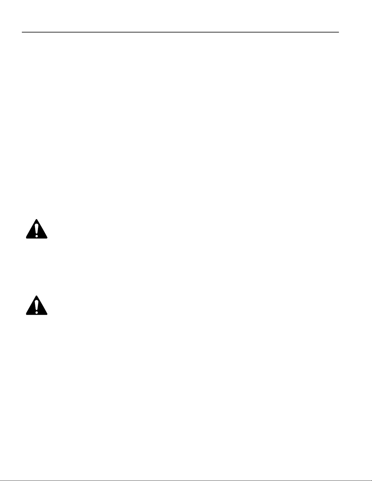
Table Top Air Cleaner
Super Air 5 / Air 6
REV I., Please disregard all earlier versions.
Model 447628 & 4478801
Page 2
Important Safeguards
When using electrical appliances consideration should be given to basic safety
precautions including:
1. Read all instructions.
2. Do not immerse appliance, cord or plug in water or other liquid and take care to ensure
that the control panel is kept clean and dry.
3. Do not use the appliance if there is any visible damage to the appliance or to the supply
cord.
4. Close supervision is necessary when any appliance is used by or near children.
5. Do not let the cord hang over the edge of the table or worktop or touch hot surfaces.
6. Do not use the appliance outdoors.
7. Do not use the appliance for other than its intended use.
WARNING: DO NOT USE THIS ELECTRONIC AIR CLEANER WHEN OXYGEN IS
8.
BEING USED OR WHEN COMBUSTIBLE GASES ARE PRESENT. HIGH VOLTAGE
SPARKS CAN CAUSE IGNITION AND SUBSEQUENT PERSONAL INJURY OR
PROPERTY DAMAGE.
NOTE: Care should be taken to avoid touching the sharp ionizer needle situated above
9.
the fan. Always disconnect the unit from power prior to cleaning or servicing.
General Knowledge Warning - The intent of this manual is to provide general
guidance to be used by a qualified service technician in servicing the Oreck tabletop electrostatic
air cleaner. The technician should have a good understanding relative to working with electrical
and mechanical equipment. A knowledge base to include basic electronics, basics of motors and
general mechanical knowledge is required to service this equipment. Attempting to service the
equipment without the above background could result in electric shock, personal injury or
property damage. Do not attempt to service equipment unless properly qualified.
Rotating Element Warning - Unit has a rotating blower wheel and cooling fan to
circulate air and keep the unit cool. When servicing the unit and repairing the unit always insure
that you keep objects and internal electrical wiring away from the rotating elements. Failure to
allow for proper clearance for rotating members can cause electric shock, personal injury or
property damage.
Tools Required
Multimeter Fluke Model 8024-B
High Voltage Probe Fluke Model 80K-40
#2 Flat Blade Screwdriver
#2 Phillips Drive Screwdriver
Diagonal Wire Cutters
Wire nuts
Needlenose Pliers
2
Page 3
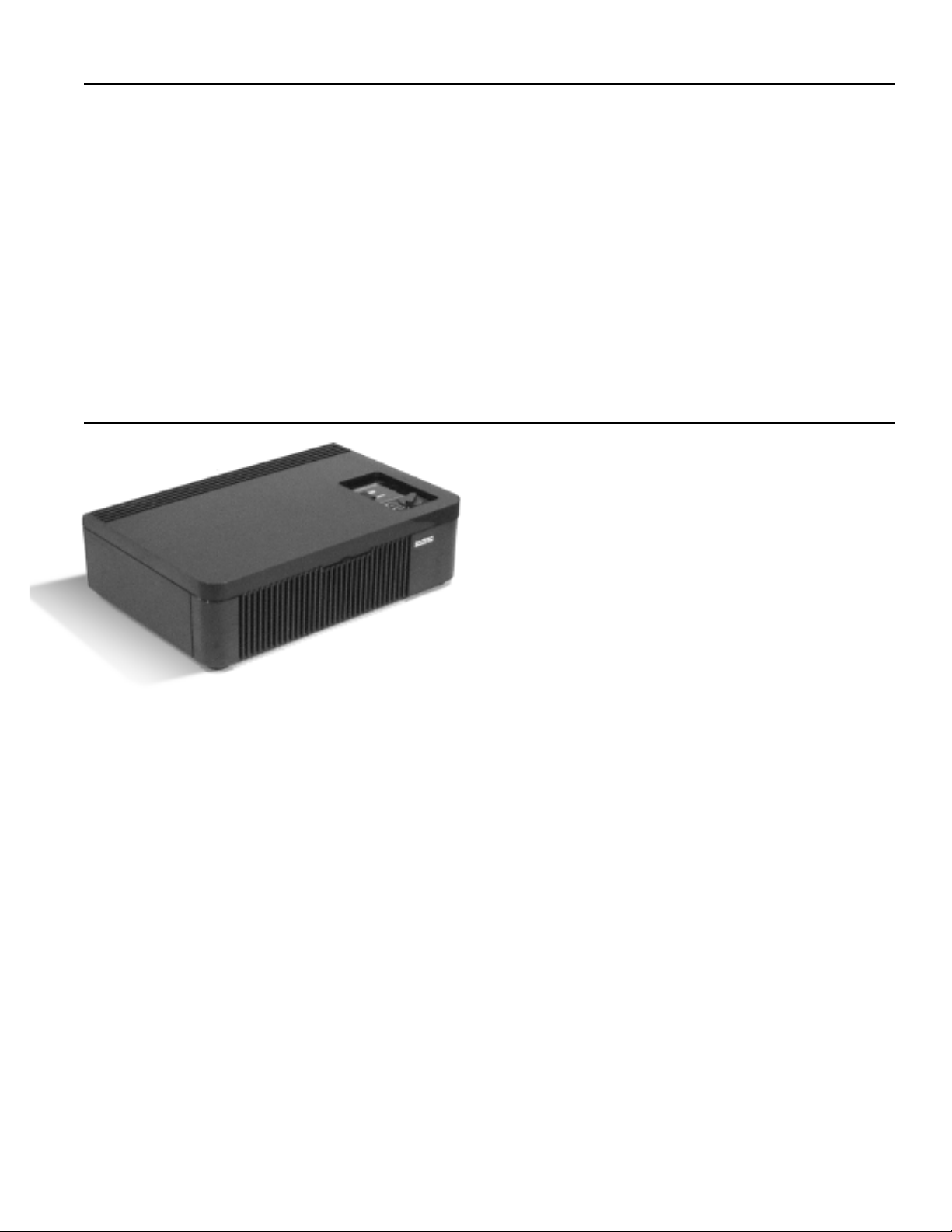
Table of Contents
General Description and Operation . . . . . . . . . . . . . . . . . . . . . . . . . . . . . . . . . . . . . . . . . . page 3
Periodic Maintenance and Tune-Up . . . . . . . . . . . . . . . . . . . . . . . . . . . . . . . . . . . . . . . . . . page 4
Trouble Shooting Guide . . . . . . . . . . . . . . . . . . . . . . . . . . . . . . . . . . . . . . . . . . . . . . . . . . . page 5
Parts Removal and Replacement Procedures . . . . . . . . . . . . . . . . . . . . . . . . . . . . . . . . . . page 15
Cross Section and Parts List . . . . . . . . . . . . . . . . . . . . . . . . . . . . . . . . . . . . . . . . . . . . . . . page 25
Wiring Diagram . . . . . . . . . . . . . . . . . . . . . . . . . . . . . . . . . . . . . . . . . . . . . . . . . . . . . . . . . page 26
General Description and Operation
Airborne particles and odors are removed from
air passing through the unit by the process of
electrostatic precipitation and the revolutionary
post filter which combines antimicrobial
treatment and activated charcoal.
The air around you is filled with thousands of particles of air
pollution. Some of the pollutants - dust, pollen and lint are visible to the naked eye, but most of
the pollutants - smoke and bacteria, to name a few, are microscopic in size.
Polluted air enters the unit through the front of the air cleaner. The fan pulls in dirty air and the
pre-filter traps large particles (hair, lint, etc.). The smaller particles (dust, smoke, pollen) in the
dirty air receive a positive electrical charge as they pass through the ionizing section. The
positive charged particles then enter the collecting section which uses a series of alternately
charged aluminum plates to attract and retain the particles. It works like a powerful magnet
and the particles remain there through natural adhesion until removed by the washing process.
The air then passes through the post filter that helps control microorganisms and remove
household odors. Next, the negative ion generator freshens stale air. Finally, clean air passes
back into the room through the top grille.
3
Page 4
Periodic Maintenance Tune-Up
1. Remove collecting cell and pre/post filters.
2. Wipe down inside of unit with damp cloth.
3. Thoroughly Clean Collecting Cell with Oreck Assail-A-Cell Cleaner.
4. Check for any broken wires in the collecting cell, and ensure wires are securely seated
in the plastic spacer at the center of the cell. Check for any bent plates in collecting cell.
Replace if damaged.
wires
plastic spacer
plates
5. Thoroughly Clean pre-filter with warm soapy water.
6. Clean negative ion generator tip with a alcohol and a cotton swab.
7. Clean the dirt and grime from the motor shaft using a soft cloth.
8. Squirt a few drops of machine oil (“3 in 1” type oil, not
WD-40 type oil) in the slot on the
shaft to lubricate the bearing.
9. Check to ensure blower wheel rotates freely.
10. Check to ensure rubber grommet on motor shaft is not worn or loose. Replace if
necessary.
11. Check the bearing in the bearing wall (opposite end of motor) on other end of blower
wheel for excessive wear or damage. Replace if necessary.
12. Re-install collecting cell and pre-filter.
13. Install New Post Filter (Activated Charcoal Filter).
4
Page 5
Troubleshooting Guide
Warning: The troubleshooting portion of this manual requires that the unit power be “ON” for
much of the servicing portion of troubleshooting. When working on the unit under power, use all
of the standard precautions in working with any electro-mechanical device that contains line
voltage, high voltage, and rotating elements. Failure to follow standard safety procedures can
cause electrical shock, personal injury or property damage.
Initially:
1. Plug the unit into a proper outlet.
2. Check the unit on all speeds to see if the blower and motor are operating properly. The
power supply light should not operate on the “fan” selection mode.
Problem Being Checked:
1. If the motor and blower do not operate
:
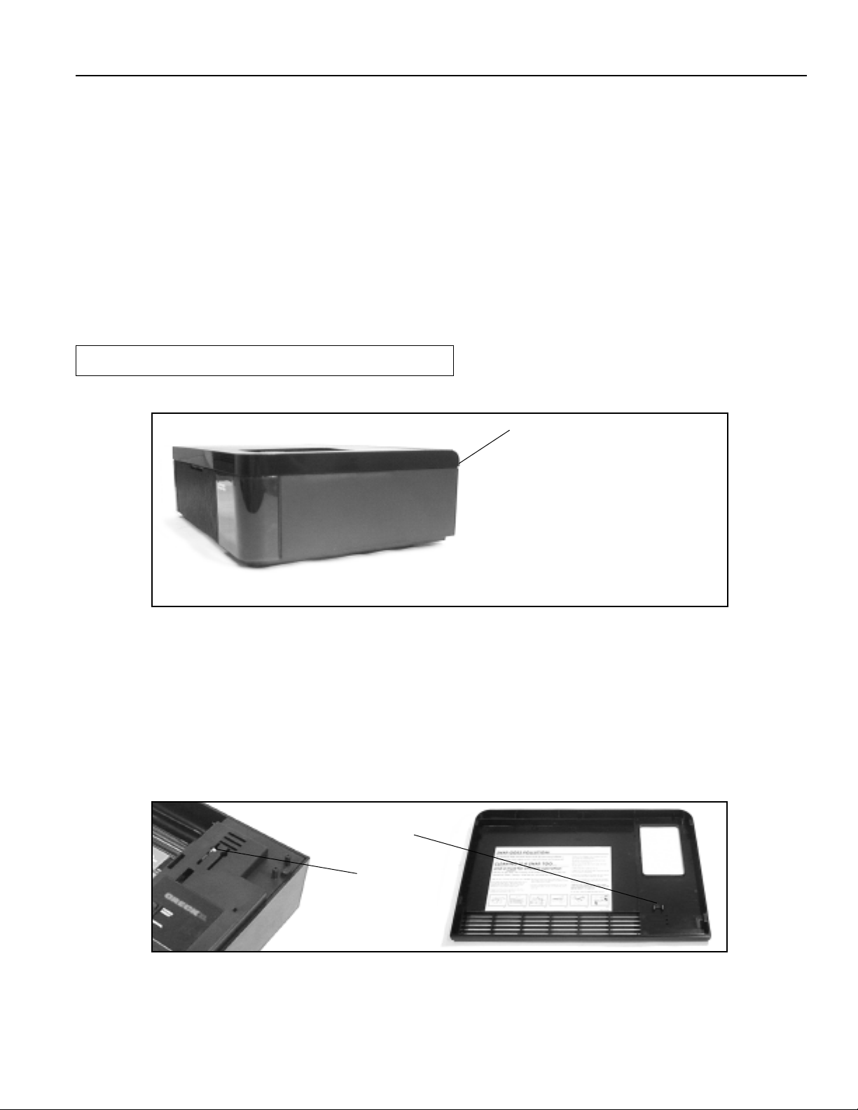
a. Check the top for proper positioning. The top must fit tightly on the unit.
Remove the top. Depress the
interlock switch with a plastic
handle screwdriver to test
operation. If the motor and
blower operate, then the
problem is that the interlock
switch is not gettting engaged
when the top is on. Reinstall
the top and ensure tight fit so
activator post can engage the
interlock switch.
b. With the top removed, depress the interlock switch with a plastic handle screwdriver to
test operation.
c. If the motor and blower operate, then the problem is that the interlock switch is not
engaged when the top is on.
d. Check the top to see if there is a broken activator post.
e. Check the top to determine if it is warped. If the top appears to be warped, try
a new top.
Activator Post
Interlock Switch
Turn the top over and examine it for a broken activator post. Lay the top on a smooth
surface. Check it for warpage that could keep the interlock switch from being engaged.
f. Check the interlock switch (item 3 of the parts diagram).
5
Page 6
Troubleshooting Guide
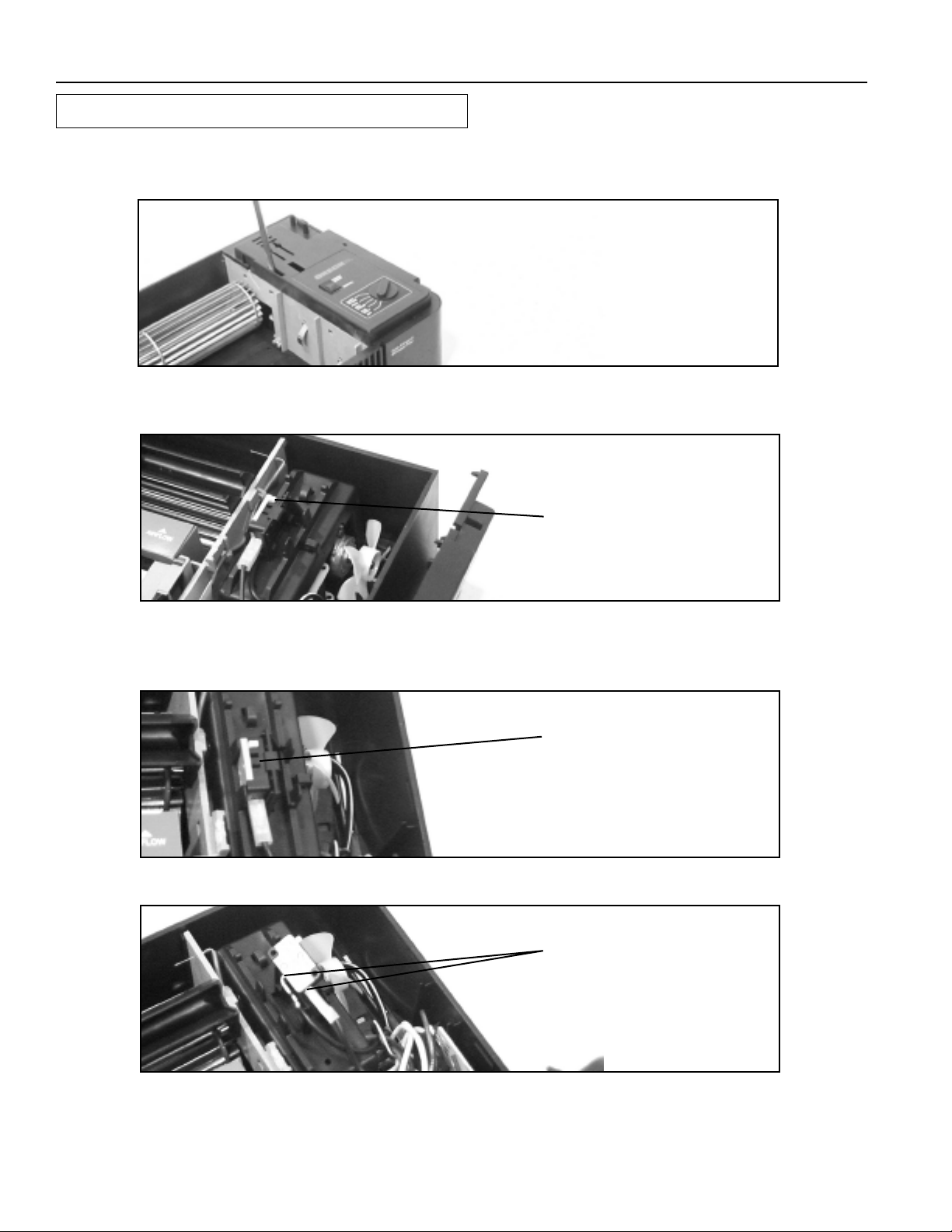
How to Remove the Power Supply Cover
1. Insert flathead screwdriver into slot on the interior edge of the power supply cover, and
push plastic clip away from contact wall so that the cover can be lifted up.
Gently pry the plastic clip
away from contact wall to
release the cover.
2. The switch wires will limit the movement of the power supply cover.
3. Is the switch actuator broken?
If the actuator is broken,
replace the switch.
4. Is the switch properly seated in the bracket, or is the bracket broken or distorted?
The switch is held in position by a bracket that allows the switch to be snapped
between two locator ribs on the bracket.
If the switch is out of
position, straighten and
secure it. If the bracket is
broken or distorted, replace
the motor bracket.
5. Are the wires connected to the switch?
Check both wires on the
interlock switch to ensure
that they are connected and
tight.
6
Page 7
Troubleshooting Guide
6. Check the voltage to and from the switch when activated. You should be able to
measure line voltage entering and leaving the switch when activated.
TO SWITCH, If voltage is
LINE SIDE
LOAD SIDE
7. Check the switch plate cover. The plate must sit squarely on the bearing wall
and the cabinet base.
present on line side of the
switch but not present on
load side, the switch is bad.
FROM SWITCH, If there is no
voltage on line side of the
switch, check the wall outlet.
If there is voltage at the
outlet, then the line cord is
bad.
If the switch plate cover is
not secure, it will prevent the
top from engaging the
interlock switch. Insure that
the cover is in position.
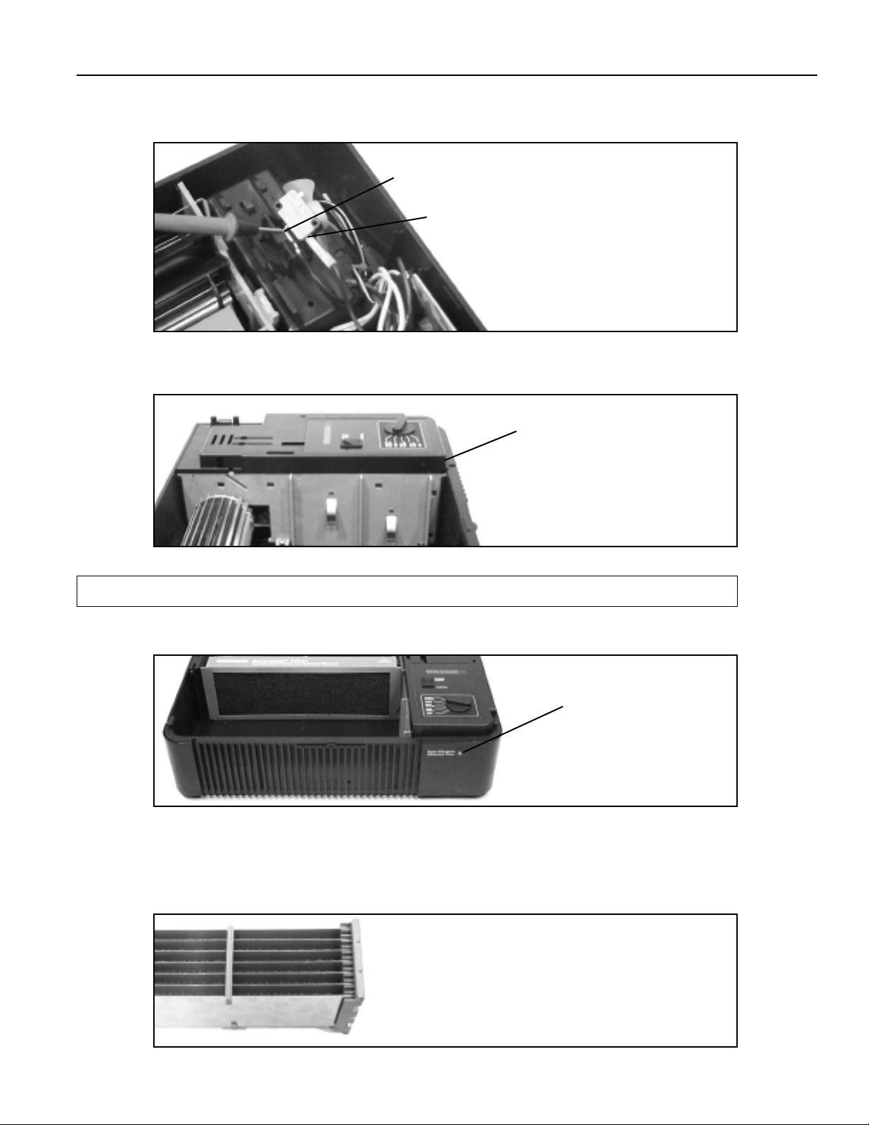
2. If the motor operates but the green “cleaning air” light does not operate:
a. Remove the cell and check to see if the “cleaning air” light comes on.
CLEANING
AIR LIGHT
b. If the light operates with the cell removed, check the cell for broken wires that
could cause a dead short. Check to see if the cell plates are bent or touching.
Check to see if there is a foreign object in the cell. Check for carbon paths or
tracks on the cell ends.
If the cell has loose or broken wires or bent plates,
replace the cell. If there are no loose or broken
wires present, hold the cell up to the light and look
for metal shavings or anything that may be causing
a short. If nothing is apparent, clear and retest the
cell. If the problem persists, replace the cell. If carbon
tracking is present on cell ends, replace the cell.
7
Page 8
Troubleshooting Guide
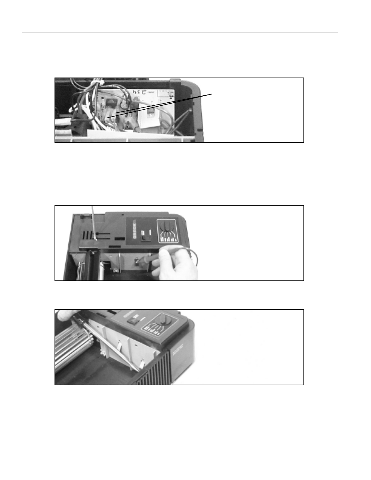
c. If the light does not operate with the cell removed, check the wires to the
light and confirm that they are properly connected. Check the voltage from
the light terminals on the power supply board. Set meter to appropriate scale.
You should have about 16 volts DC.
d. Option 1: Check the output of the power supply by using the recommended H.V.
probe and a multimeter. The unit must be "ON" with the operating switch in the
"Max Clean" position and the interlock switch must be depressed. The voltage
should measure from -5.5 KVDC to -7.0 KVDC. An alternate method to check
voltage is by using a plastic handled screwdriver to short the high voltage
contacts and observe a spark.
If the wire has voltage, the
light is bad and needs to be
replaced. If the wire does
not have voltage, go to
next step.
If the voltage is not present,
check the transformer output.
If the voltage is present and not
within range, replace the power
supply board and check the
transformer output. If the
voltage is present and within
range, the power supply is
operating properly.
Option 2: Using a plastic handle screwdriver, short the high voltage contacts
and observe a spark.
Short the HV contacts to
observe a spark.
8
Page 9
Troubleshooting Guide
e. Check the input voltage to the transformer using a standard lead and a multimeter.
Check the voltage from the black lead on the terminal L speed control switch and white
lead on power supply board labeled line neutral. Activate the interlock switch. The
meter should indicate line voltage. Check the voltage on the two yellow wires on the
power supply board from the transformer. The interlock switch must be activated. The
meter must indicate 24 vac.
BLACK LEAD
YELLOW WIRES
WHITE LEAD
If there is no power to the
transformer, recheck
section 1, the interlock
switch.
If there is power to the
transformer, but no output
voltage, replace the
transformer and power
supply board assembly.
3. If the green “cleaning air” light operates and the blower wheel does not turn.
a. Remove the top and check to see if the stripper is in place.
The stripper is held in
position by slots in the
contact wall and bearing
plate and alignment tabs on
the stripper plate. If the
stripper is not in position,
reposition the plate by
placing tabs into the slots.
b. Use your hand to try to spin the blower wheel.
If the wheel does not spin
freely, check for anything
that may be blocking the
movement of the wheel and
remove the blockage. If no
blockage is apparent, see
3c and 3d
c. Turn the unit over and check for signs of distortion in the cabinet bottom beneath the
motor that might prevent the blower from spinning.
If the cabinet bottom is
distorted, replace the unit.
9
Page 10

Troubleshooting Guide
d. If there are no signs of distortion, remove the blower wheel (see: Blower Wheel
Removal
wheel. If the motor shaft operates, the problem is related to the blower wheel.
4. If the motor shaft does not turn on all speeds, or seems sluggish, it may be due to a
build-up of dirt and grime on the motor shaft. To remedy this.
a. Clean the dirt and grime from the motor shaft using a soft cloth.
) and activate the unit. Notice if the motor shaft rotates without the blower
If the motor shaft rotates
then replace the blower
wheel drive grommet and
bearing wall. If the motor
shaft does not rotate, replace
the motor.
Motor Shaft
b. Squirt a few drops of lubricating oil (“3 in 1” type oil, not WD-40 type oil) in the slot on
the shaft to lubricate the bearing.
5. If the blower wheel vibrates:
a. Check for bent or warped blades.
Replace the blower wheel if
blades appear warped or
bent.
b. Check for loose or worn drive grommet.
Replace the drive grommet.
10
Page 11

Troubleshooting Guide
c. Check to see if the blower wheel is adequately supported by the outside bearing
plate assembly.
d. Check to see if the motor mounting bracket snap tabs are in place or are loose.
Look into the four base slots to see the tabs.
The outboard end of the blower wheel should be
firmly supported, allowing no
rotation. If that end of the wheel can be moved front
to back and up and down, remove the bearing plate
assembly and check the bearing for damage or
excessive wear. Replace parts as needed. Use care
in handling the blower wheel. Do not distort the
wheel blades. On reassembly, insert the outboard
wheel shaft into the bearing plate then position the
plate into the cabinet. The blower wheel should be
positioned so that the clearance between the ends of
the wheel and the adjacent walls are approximately
equal on both sides. If the wheel is too close it may
drag on the wall. Too much clearance at the outboard
end may cause the wheel shaft to slip out of the
outboard bearing.
movement other than
If the tabs are not in position,
use a screwdriver inserted
into slots to push the tabs
out of the slot. You may
need to twist the screwdriver
slightly to disengage the
snaps. Inspect the mounting
bracket; replace it if
damaged. Check for broken
mounting tabs, distorted
bracket (because of
excessive heat). A distorted
motor bracket normally
indicates motor overheating.
The motor should be
replaced.
e. Check to see if the motor is loose in the support bracket by holding the bracket
and trying to move the motor. If the motor moves, remove the mounting bracket to
check the isolator pads
Insure that the isolator pads
are in position. Replace if the
motor moved while being
held in place with mounting
bracket.
11
Page 12

Troubleshooting Guide
6 If the cell is arcing, check the following:
a. If there are loose or broken ionizer wires.
b. If the cell is dirty. Remove the cell and wash with warm soapy water. Dry completely
before re-installing.
c. If there are bent cell plates.
Replace the cell.
Replace the cell by following
instructions on inside of
cabinet top.
d. If the cell is improperly installed in the unit.
e. If the cell contacts are broken or loose.
CELL CONTACTS
Reinstall the cell.
Replace the cell.
12
Page 13

Troubleshooting Guide
f. If the H.V. contacts are not properly aligned or the contact wall is not properly
aligned.
The H.V. contacts must make
good contact. Replace the
contact wall or straighten the
contacts, if possible.
7. Checking for ionizing needle operation. Using HV voltage probe check needle for
high voltage -5.5 KVDC to -7.0 KVDC.
a. If voltage is present, the ionizer is OK.
Clean needle with alcohol
and a cotton swab.
b. If voltage is not present, check HV power supply.
See above diagram.
c. If voltage is present at HV power supply but not the needle.
Replace the negative ionizer
assembly including wire,
with needle attached, and
terminal.
IMPORTANT: Replace using
wire routing on contact
board.
13
Page 14

Notes
_____________________________________________________________________________
_____________________________________________________________________________
_____________________________________________________________________________
_____________________________________________________________________________
_____________________________________________________________________________
_____________________________________________________________________________
_____________________________________________________________________________
_____________________________________________________________________________
_____________________________________________________________________________
_____________________________________________________________________________
_____________________________________________________________________________
_____________________________________________________________________________
_____________________________________________________________________________
_____________________________________________________________________________
_____________________________________________________________________________
_____________________________________________________________________________
_____________________________________________________________________________
_____________________________________________________________________________
_____________________________________________________________________________
_____________________________________________________________________________
_____________________________________________________________________________
_____________________________________________________________________________
_____________________________________________________________________________
_____________________________________________________________________________
_____________________________________________________________________________
_____________________________________________________________________________
_____________________________________________________________________________
_____________________________________________________________________________
14
Page 15

Super Air 5 Model 447628
Parts Removal and Replacement
General Parts Replacement
Motor Removal and Replacement page 16
Power Supply Removal and Replacement page 19
Transformer Removal and Replacement page 21
Bearing Wall Assembly and
Blower Wheel Removal and Replacement page 22
Led Assembly Removal and Replacement page 23
Cell Assembly Removal and Replacement page 23
Ionizer Needle Removal and Replacement page 23
Fan Blade Removal and Replacement page 24
Warning - All parts removal and replacement should
be performed with power disconnected from the unit.
15
Page 16

General Parts Replacement
Motor Removal and Replacement
1. Remove the cabinet top by pressing
down the thumb latch and sliding the
top forward.
2. Remove the cell assembly (see inside
of top for instructions).
3. Remove the stripper by pulling it
to the right and applying pressure to
the bearing wall. Lift the left hand side
of the stripper out of the bearing wall
locator seat and then remove the
stripper.
4. Flip the unit onto its side with the
bearing wall up and release the two
locking tabs for the bearing wall
assembly by using a regular
screwdriver from the bottom. Place
screwdriver blade into the slot on top
of the snap finger locking tab and twist
the blade slightly while pulling on the
bearing plate. Repeat for the second
tab. The bearing wall may now be
removed by moving the blower wheel
and bearing wall away from the cabinet
and lifting the bearing wall off of the
blower wheel.
16
Page 17

General Parts Replacement
ROTATING ELEMENT WARNING - Unit has a rotating blower wheel and cooling
fan to circulate air and keep the unit cool. When servicing the unit and repairing
the unit always insure that you keep objects and internal electrical wiring away
from the rotating elements. Failure to allow for proper clearance for rotating
members can cause electric shock, personal injury or property damage.
5. Remove the blower wheel by gently
grasping the outside of the wheel at the
center support rib and the rib closest
to the motor. Tilt the wheel up and pull
it away from the motor shaft. The blower
wheel rubber grommet is glued to the
shaft of the motor and will remain
attached to the motor.
6. Remove the power supply cover by
placing a screwdriver blade in the cover
slot with the blade inserted on the blower
wheel side of the slot. Catch the tan snap
tab and twist the screwdriver slightly while
lifting up on the cover and remove the
power supply cover assembly. Lay the
assembly aside out of the way.
7. Remove the interlock switch from the
mounting bracket by releasing the snap
lever and lifting the switch out of the
bracket. It is not necessary to disconnect
the switch wires.
8. Turn the unit over. Use a screwdriver to
release the motor mounting bracket
locking tabs by inserting the screwdriver
blade between the snap tab and the
housing. Twist the snap tab toward the
center of the four motor mounting slots.
You will need to pull the mounting bracket
away from the cabinet while releasing the
tabs. After releasing all four tabs, remove
the bracket.
SLOTS
17
Page 18

General Parts Replacement
HIGH VOLTAGE WARNING - This equipment is supplied with line voltage from a
standard wall socket. Use standard precautions in working on it with line voltage
applied. Failure to practice normal electrical safety precautions can cause
electrical shock, personal injury or property damage.
9. Unplug the red terminal (3), brown
terminal (2) and black terminal (1) wires
from the selector switch by pushing a
paper clip (straightened) under the wire
into the switch while pulling on the wire
lightly.
10. Remove the white motor wire from the
power supply board line neutral
connection.
11. Remove the motor and replace it with the
new motor.
12. Reverse the above steps to replace the
motor.
13. It is important that the motor isolators are
installed correctly and are seated as
designed. Contacts on side of insulator
should fit over motor bearing bracket.
Motor and isolators must fit securely.
MOTOR WIRE
ISOLATOR PAD
18
Page 19

General Parts Replacement
Power Supply Removal and Replacement
1. Follow steps 1, 3, and 6 of Motor Removal and Replacement.
EXTREME HIGH VOLTAGE WARNING - This equipment is supplied with line
voltage from a standard electrical wall socket. That voltage is transformed to a
24V signal that is then amplified to over 6000VDC. In working with the equipment
you must always know the voltage level for the equipment and wiring. Attempting
to measure or work with the 6000 VDC power without using the proper high
voltage probe can cause electrical shock, personal injury or property damage.
Probing a high voltage without the proper meter will potentially damage the volt meter.
EXTREME HIGH VOLTAGE WIRING WARNING - The unit has been designed
such that extremely high cell collector voltage wiring is isolated from all other
wiring. Special wiring routing holders have been designed into the unit. This
extremely high voltage wiring must be routed correctly. Failure to route and isolate
the wire can create a fire hazard, personal injury or property damage.
INSULATOR BOARD WARNING - The unit has been designed with special
insulator and isolator spacer boards that must be in position. These boards are
made of a special insulator material and must be in position to properly isolate
wiring and connectors from uninsulated parts. Failure to place the boards in the
proper location can create a fire hazard, cause personal injury, or property damage.
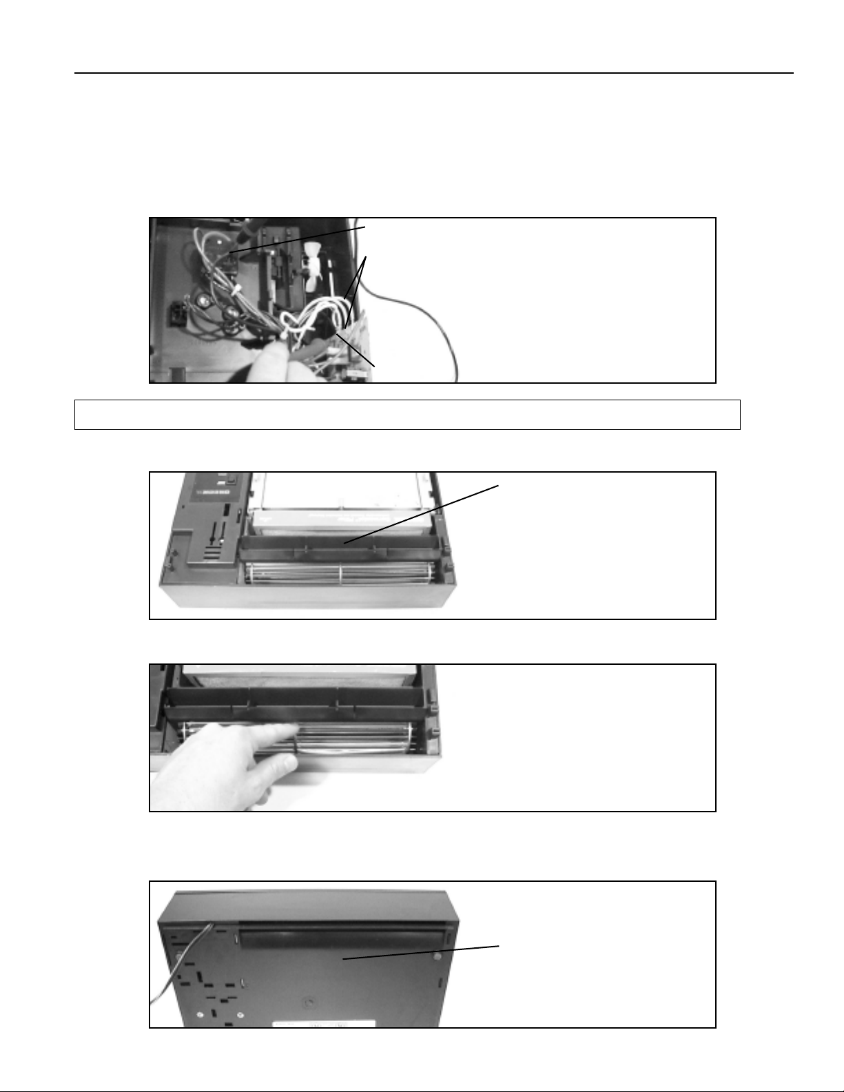
2. Before removing the HV power supply
board make note of the position of all
the wiring. You will note that all wiring is
bound and well away from the motor
fan. The HV power single red line
coming from the left hand side of the
board is routed in special built-in plastic
routing holders and isolated from all
other wires. Note that the routing and
isolation is critical and must not be
altered. In addition, the two insulator
sheets are preset and must be in
position. After carefully noting the
above, remove the HV power supply
board by first removing the HV red lead
from the bottom holder. You can now lift
the board up and rotate it into a position
to allow the connectors to be removed.
Reconnect the replacement board by
carefully removing one wire at a time
from the connected board and placing it
on the same location on the
replacement board.
19
Page 20

General Parts Replacement
All leads must be connected to the new board properly. The HV power line must be
isolated and properly routed. Two insulator sheets must be in position and all wiring must
be captured to prevent contact with rotating elements. A wiring diagram is included in the
service manual for your use.
3. The new board may now be reinstalled in
the housing by sliding it back into position.
The housing has two board reference ribs
molded in the bottom that hold the board
in position. Position the board between
the side wall and the reference ribs. You
may need to hold the board in place
before and during installation of the power
supply cover.
ROTATING ELEMENT WARNING - Unit has a rotating blower wheel and cooling
fan to circulate air and keep the unit cool. When servicing the unit and repairing
the unit always insure that you keep objects and internal electrical wiring away
from the rotating elements. Failure to allow for proper clearance for rotating
members can cause electric shock, personal injury or property damage.
4. The power supply cover may now be
reinstalled. Check wiring to insure it is
routed properly and cannot contact motor
fan and is properly isolated. Install the
power supply cover by placing the cover
locator tabs into the cabinet at an angle
while rotating it into place. The locking
snap should engage when in the final
position.
EXTREME HIGH VOLTAGE WARNING - This equipment is supplied with high
voltage from a standard electrical wall socket. That voltage is transformed to a 24V
signal that is then amplified to over 6000 VDC. In working with the equipment you
must always know the voltage level for the equipment and wiring. Attempting to
measure or work with the 6000 VDC power without using the proper high voltage
probe can cause electrical shock, personal injury or property damage. Measuring
high voltage without the proper meter and probe will potentially damage the volt meter.
20
Page 21

General Parts Replacement
5. To test the power supply, touch the metal
shaft of a screwdriver, with an insulated or
plastic handle, to one of the contacts while
keeping the screwdriver tip about 1/8"
away from the other contact. You should
see an arc and hear a snapping sound.
6. Reverse step 1.
Transformer Removal and Replacement
1. Follow steps 1, 2, 3, and 6 of Motor
Removal and Replacement
Remove two #6 screws and nuts that
secure the transformer to the cabinet
bottom. Save for installment of the new
transformer.
.
HIGH VOLTAGE WARNING - This equipment is supplied with line voltage from a
standard wall socket. Use standard precautions in working on it with line voltage
applied. Failure to practice normal electrical safety precautions can cause
electrical shock, personal injury or property damage.
ROTATING ELEMENT WARNING - Unit has a rotating blower wheel and cooling
fan to circulate air and keep the unit cool. When servicing the unit and repairing
the unit always insure that you keep objects and internal electrical wiring away
from the rotating elements. Failure to allow for proper clearance for rotating
members can cause electric shock, personal injury or property damage.
2. Remove the power supply and disconnect
the yellow low voltage leads and white line
voltage lead. Remove the black input line
to selector switch position 4 using a
straightened paper clip inserted into the
selector switch connection.
21
Page 22

General Parts Replacement
3. Remove the two #8/32 lockwasher nuts
and remove the transformer and replace it
with the new unit.
4. Reverse the above steps 1,2, and 3 to
replace the transformer.
Bearing Wall Assembly and Blower Wheel Removal and Replacement
1. Follow steps 1, 2, 3, 4 and 5 of Motor Removal and Replacement.
2. The rubber grommet will need to be
removed from the motor shaft. This can
be done by cutting it off using a sharp
razor knife and slitting the grommet along
the motor shaft axis. You can then peel
the grommet off of the shaft. The motor
shaft must be clean before installing the
new blower wheel and grommet. Using a
razor knife, carefully remove any sealant
on the shaft and wipe it with a clean cloth.
3. You are now ready to reinstall the new
lower wheel and grommet assembly.
Place one drop of adhesive (loctite 401 or
equivalent "super glue" type adhesive) on
the motor shaft in the small groove about
1/2" from the blower wheel attachment
end. Place the new bearing wall
assembly on the blower wheel shaft.
Slide the grommet on to the motor shaft
and rotate the bearing wall and blower into
position. Snap the wall into the cabinet.
Move the blower wheel so that the tips of
the blades are about 1/4" from the bearing
wall.
4. Reverse the above steps 1, 2 and 3 and to replace the bearing wall and blower wheel.
22
Page 23

General Parts Replacement
Led Assembly Removal and Replacement
1. Follow steps 1, 2, and 6 of Motor Removal and Replacement.
2. Disconnect the two red led leads from the
power supply board and remove the led
assembly by removing the led retaining
ring from the back of the front panel and
removing the led and the leads.
3. Replace with a new led assembly.
4. Reverse the above steps 1 and 2 to
replace the led assembly.
Cell Assembly Removal and Replacement
1. Follow steps 1and 2 of Motor Removal and Replacement.
LED LEADS
2. Replace with a new cell.
3. Reverse the above step 1 to replace the
cell.
Ionizer Needle Removal and Replacement
1. Follow steps 1, 3, and 6 of Motor Removal and Replacement.
EXTREME HIGH VOLTAGE WARNING - This equipment is supplied with line
voltage from a standard electrical wall socket. That voltage is transformed to a
24V signal that is then amplified to over 6000 VDC. In working with the equipment
you must always know the voltage level for the equipment and wiring. Attempting
to measure or work with the 6000 VDC power without using the proper high
voltage probe can cause electrical shock, personal injury or property damage.
Probing a high voltage without the proper meter will potentially damage the volt
meter.
23
Page 24

General Parts Replacement
EXTREME HIGH VOLTAGE WIRING WARNING - The unit has been designed
such that extremely high cell collector voltage wiring is isolated from all other
wiring. Special wiring routing holders have been designed into the unit. This
extremely high voltage wiring must be routed correctly. Failure to route and isolate
the wire can create a fire hazard, personal injury or property damage.
2. Carefully remove the ionizer needle
assembly that is the piece of red insulated
wire with fast on connection on one end
and the needle on the other end. Replace
with new needle assembly.
3. Reverse step 1 above to replace
assembly.
IONIZER NEEDLE
ASSEMBLY
Fan Blade Removal and Replacement
1. Follow steps 1, 2, 3, and 6 of Motor Removal and Replacement.
ROTATING ELEMENT WARNING - Unit has a rotating blower wheel and cooling
fan to circulate air and keep the unit cool. When servicing the unit and repairing
the unit always insure that you keep objects and internal electrical wiring away
from the rotating elements. Failure to allow for proper clearance for rotating
members can cause electric shock, personal injury or property damage.
2. Remove fan with flathead screwdriver by
lightly prying the fan off of the motor shaft.
3. Replace the fan with the new fan and
insure that the new fan is installed on the
motor shaft with the metal locking collar
closest to the motor body. Press the fan
onto the shaft and allow about 1/4"
distance between the motor end bracket
and the fan hub. Spin the fan to ensure it
is clear of all objects.
4. Reverse above step 1 above to replace
the fan.
24
Page 25

Parts List
QTY
ITEM # PART NO. DESCRIPTION
1
1
1
1 4 247135-001 FAN BLADE
2 5 AT2PK CHARCOAL COMBINATION FILTER
1 6 247667-001 CONTROL LABEL
1 7 342472-002 CONTACT WALL ASSEMBLY
1 8 342480-003 PLASTIC MESH PREFILTER
1 9 254682-001 BLOWER WHEEL KIT
1 10 254681-001 MOTOR KIT (BALL BEARING MOTOR DOES NOT REQUIRE COOLING FAN)
1 11 451686-003 CABINET TOP, GRAY
1 12 442415-101 COLLECTOR CELL
1 13 142475-001 ION NEEDLE ASSEMBLY
1 14 342228-001 STRIPPER
1 15 342227-001 MOTOR MOUNTING BRACKET
1 16 136483-001 DRIVE GROMMET
1 17 342402-251 HV POWER SUPPLY BOARD
1 342402-254 HV POWER SUPPLY BOARD “HUMP BACK”
1 18 442223-201 CABINET BOTTOM
2 19 242253-001 MOTOR ISOLATOR PAD
1 20 142581-001 SWITCH ASSEMBLY
1 21 145820-002 SWITCH ROCKER
1 40184-01 CARTON
1 442414-001 CARTON INSERT
2 NLA 20CFT CHARCOAL FILTERS (NO LONGER AVAILABLE)
3 30CFT CHARCOAL FILTERS
1 33358 CELL CLEANER
1 242809-015 OWNER’S MANUAL
1 242235-001 SWITCH KNOB, BLACK
2 242331-007 TRANSFORMER
3 242404-001 INTERLOCK SWITCH
12
11
5
8
14
1
6
18
21
20
9
7
25
13
16
2
17
3
15
19
10
4
19
Page 26

L
INE
CORD
INTERLOCK
S
WITCH
P
OWER SWITCH
BLK (HI)
B
LOWER
W
HT
B
LK
1
20V
WHT
2
4V
LED
R
ED
L
INE NEW
1 2
LED
FUSE
HV POWER SUPPLY
R
ED
Y
EL
YEL
R
ED (142475-001)
GRN (242477-027)
G
RN
RED
BLUE (242477-035)
ION./COLL. CELL
POWER BOOST
SWITCH
B
LUE (242477-035)
CONTACT WALL
GRN
GRN
BLACK (RIBBED)
B
RN (MED)
RED (LO)
B
LACK (RIBBED)
1
20V, 60HZ
P
OWER
SWITCH
O
UTPUT
POS 1 OFF
POS 2 L-1
POS 3 L-1,4
POS 4 L-2,4
P
OS 5 L-3,4
Wiring Diagram
2004 Oreck Holdings, LLC.
©
All rights reserved.
All trademarks are owned and used under the authority of Oreck Holdings, LLC.
75422-01
Page 27

Notes
_____________________________________________________________________________
_____________________________________________________________________________
_____________________________________________________________________________
_____________________________________________________________________________
_____________________________________________________________________________
_____________________________________________________________________________
_____________________________________________________________________________
_____________________________________________________________________________
_____________________________________________________________________________
_____________________________________________________________________________
_____________________________________________________________________________
_____________________________________________________________________________
_____________________________________________________________________________
_____________________________________________________________________________
_____________________________________________________________________________
_____________________________________________________________________________
_____________________________________________________________________________
_____________________________________________________________________________
_____________________________________________________________________________
_____________________________________________________________________________
_____________________________________________________________________________
_____________________________________________________________________________
_____________________________________________________________________________
_____________________________________________________________________________
_____________________________________________________________________________
_____________________________________________________________________________
_____________________________________________________________________________
_____________________________________________________________________________
27
Page 28

©2004 Oreck Holdings, LLC. All rights reserved. All trademarks are owned and used under the authority of Oreck Holdings, LLC.
75422-01 REV I 08/04
R-7693, R-7695
 Loading...