


Sprinkler Valve System
Instruction Manual
|
|
PROOF NO: 3 |
|
|
|
DATE: 09.16.09 |
|
|
|
DES: SM SPCK: XX |
|
|
|
JOB NO: NA |
|
|
|
||
|
|
CLIENT: Orbit |
|
|
|
SKU: 57250 |
|
|
|
||
P 801 295 9820 |
UPC:NA |
||
F 801 951 5815 |
|||
|
|||
www.fluid-studio.net |
FILE NAME: 57250-24 rB.indd |
||
1065 South 500 West |
SOFTWARE: InDesign CS3 |
||
Bountiful, Utah 84010 |
|||
|
|
|
|
DIMENSIONS:
FLAT: W: 12" H: 8.5"
FINISHED: W 6" D: " H 8.5"
COLORS
|
|
|
color |
|
color |
|
|
|
Registration |
|
non printing |
|
non printing |
|
|
|
|
|
PMS |
|
PMS |
|
PMS |
|
|
|
|
|
|||
|
K |
|
???? |
|
???? |
|
???? |
ADDITIONAL INSTRUCTIONS:
·Font sizes cannot be smaller than 7 pt.
·Translation Approval code: LB410377
Printers are responsible for meeting print production requirements. Any changes must be approved by the client and Fluid Studio.
PRINTED PIECE MUST MEET DESIGNATED SPECIFICATIONS ON THIS FORM.
© 2007 Fluid Studio. This work is the property of Fluid Studio, and cannot be used, reproduced or distributed in any way without their express permission.
Important Guidelines
•Warning: DO NOT use pipe dope on threads, use thread seal tape
•Place the manifold so that water drains away from the house
•If not using culinary water, install a filter upstream of the manifold
Valve Placement
1.Select a location for the Sprinkler Valve System with the following criteria:
•Accessible to water supply line
•Accessible to sprinkler wire from timer
•Elevated ground—avoid low areas where water will accumulate in valve box
2.Use an Orbit® valve box (not included) to protect the sprinkler valve system
3.Once a location is selected, dig a hole in the ground deep enough so
the top of the valve box will be flat and level with the surface.
Tip: Orbit® recommends placing 1" to 1 ½" of gravel below the valve box for drainage
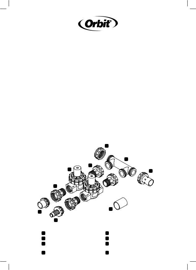
|
A |
|
B |
|
D |
E |
C |
|
D
H
F
G
A |
End Cap |
E |
1" Female Thread Valve |
B 1, 2, or 3 Port Manifold |
F |
PVC Transition Adapter |
|
C |
PVC Swivel Adapter |
G ¾" or 1" Poly Adapter |
|
|
(connects to sprinkler mainline) |
|
(not included) |
D |
1" Swivel Adapters |
H |
Coupler |
Ins
1.
2.
3.
4.

Installation
|
|
1. Check each fitting connection to |
|
|
make sure it is hand-tight. |
|
|
Warning: DO NOT use wrenches, |
|
|
channel locks, or other tools to |
|
|
tighten fittings |
|
|
2. Check to make sure that the flow |
|
|
direction arrow (located on the |
|
|
body of the valve) is pointed away |
|
|
from the manifold |
|
|
3. Connect the manifold to PVC |
|
|
mainline using PVC cement |
em |
|
• For ¾" PVC pipe, connect |
|
directly to Swivel Adapter (C) |
|
o |
|
(Figure 1) |
e |
|
• For 1" PVC pipe, use a Coupler |
|
(H) between PVC Swivel Adapter |
|
|
|
and pipe (Figure 2) |
|
|
• For larger size mainline, |
|
|
purchase and install reducer |
|
|
4. Connect your Sprinkler Valve |
|
|
System to your sprinkler header |
|
|
lines (sprinkler lines directly after |
|
|
the valve) |
|
|
• For ¾" PVC pipe, connect |
|
|
directly to Transition Adapter (F) |
|
|
(Figure 3) |
|
|
• For 1" PVC pipe, use Coupler |
|
|
(H) between Transition Adapter |
|
|
and pipe (Figure 4) |
|
|
• For ¾" or 1" Poly Pipe, use |
|
|
Poly Adapter (included in |
|
|
91207/91206) and secure with |
|
|
tubing clamp (Figure 5) |
|
|
|
Figure 1
Figure 2
Figure 3
Figure 4
Figure 5
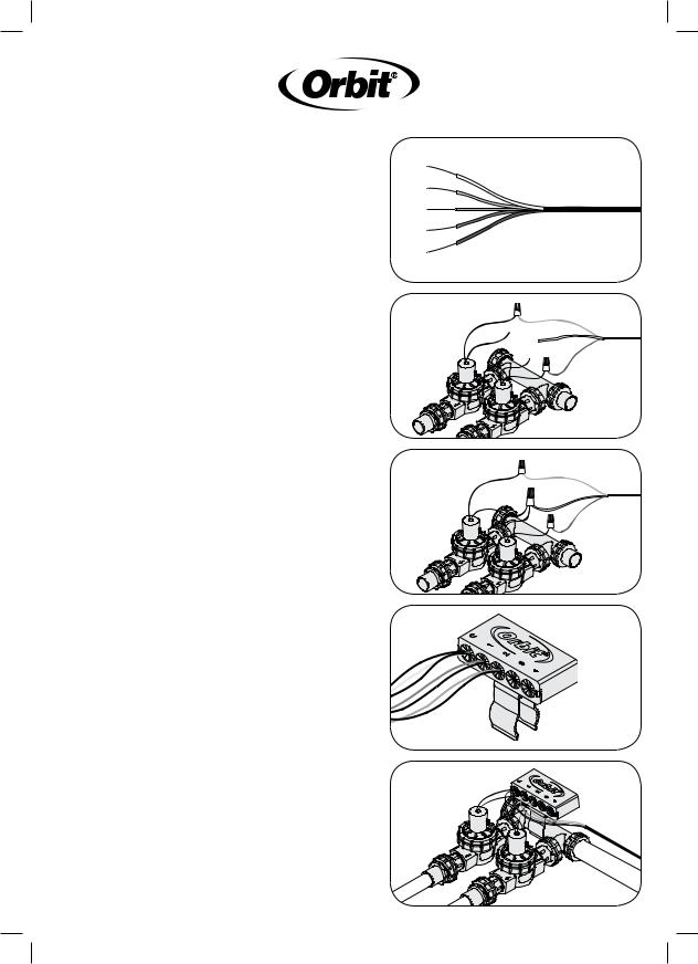
“Easy Wire” Connection
Note: The “Easy Wire” System should only be used on 24-Volt sprinkler timers with Class II circuits. All wiring must conform to applicable local codes.
1.Disconnect power to your sprinkler timer
2.Run sprinkler wire (use 16ga–20ga wire) from your timer to the manifold assembly
3.Remove 4"–5" of the outer
insulation of the sprinkler wire Warning: Avoid cutting into the wires inside
4.Remove 7/8"–1" of insulation from each individual wire (Figure 6)
5.Insert one wire from the valve and a colored wire from the timer into the wire nut and twist to lock the wires in the wire nut. One wire should be used for each zone with an additional wire to be used for a common (for ease of identification,
use the white wire as the common). Note: The wire should hold firm when lightly pulled. If the wire moves freely, remove the wire and repeat Step 5. (Figure 7)
6.Take the second wire from each valve and the white common wire from the timer and twist them into the wire nut (Figure 8)
7.Insert each wire nut into the corresponding cavity inside the “Easy Wire” Organizer (Figure 9)
8.Slide the “Easy Wire” Organizer onto the mounting bracket and attach to the valve manifold (Figure 10)
Tes
War rec 1.
2.
Figure 6
3.
4.
Figure 7
Figure 8
Figure 9
Figure 10
 Loading...