

Orbit 57071, 57271, 57070, 57270, 27680 Installation Manual
...
Installation Manual/User’s Manual
Programmateurs d’installation/Manuel d’utilisation
Manual de instalación/Manual del usuario
Installation Manual /
User’s Manual
Models 57071, 57271, 27681 Models: 57070, 57270, 27680
WTM230900 57071-24 rA.qxd 4/11/03 8:03 PM Page 1
TABLE OF CONTENTS
3
2
ENGLISH
1. Introduction . . . . . . . . . . . . . . . . . . . . . . . . . . . . . . . . . . . . . . . . . . . . . . . . . . .3
2. Installation Instructions . . . . . . . . . . . . . . . . . . . . . . . . . . . . . . . . . . . . . . . .7
3. Operation Checks . . . . . . . . . . . . . . . . . . . . . . . . . . . . . . . . . . . . . . . . . . . .10
4. Adjustments and Operation . . . . . . . . . . . . . . . . . . . . . . . . . . . . . . . . . . . . .13
5. Troubleshooting . . . . . . . . . . . . . . . . . . . . . . . . . . . . . . . . . . . . . . . . . . . . . .18
FRANCAIS
1. Introduction . . . . . . . . . . . . . . . . . . . . . . . . . . . . . . . . . . . . . . . . . . . . . . . . . .22
2. Instructions d’installation . . . . . . . . . . . . . . . . . . . . . . . . . . . . . . . . . . . . . .26
3. Contrôles du fonctionnement . . . . . . . . . . . . . . . . . . . . . . . . . . . . . . . . . . .29
4. Réglages et utilisation . . . . . . . . . . . . . . . . . . . . . . . . . . . . . . . . . . . . . . . . .32
5. Résolution des problèmes . . . . . . . . . . . . . . . . . . . . . . . . . . . . . . . . . . . . . .38
ESPAÑOL
1. Introducción . . . . . . . . . . . . . . . . . . . . . . . . . . . . . . . . . . . . . . . . . . . . . . . . .42
2. Instrucciones de instalación . . . . . . . . . . . . . . . . . . . . . . . . . . . . . . . . . . . .46
3. Comprobaciones de funcionamiento . . . . . . . . . . . . . . . . . . . . . . . . . . . . .49
4. Ajustes y operación . . . . . . . . . . . . . . . . . . . . . . . . . . . . . . . . . . . . . . . . . . .52
5. Resolución de problemas . . . . . . . . . . . . . . . . . . . . . . . . . . . . . . . . . . . . . . .58
ENGLISH
Thank you for selecting an Orbit®Wireless Rain / Freeze Sensor. This Orbit
®
Sensor provides conservation, convenience, and flexibility to your fully
automatic watering system. Never again will you see your sprinklers running
on a rainy day. Now, after a set amount of rain has fallen, the sensor will
send a wireless signal to the receiver and prevent the timer from watering.
The added freeze sensor will provide peace of mind (when temperatures
drops below 37°F (3°C) by interrupting your sprinklers and reduce the hazards
of standing water freezing on your driveway, sidewalks, and patios.
Please read this manual completely before you install and use the sensor.
A few of the notable design features include:
RF Communication
RF (Radio Frequency) technology eliminates unsightly wires and simplifies
mounting.
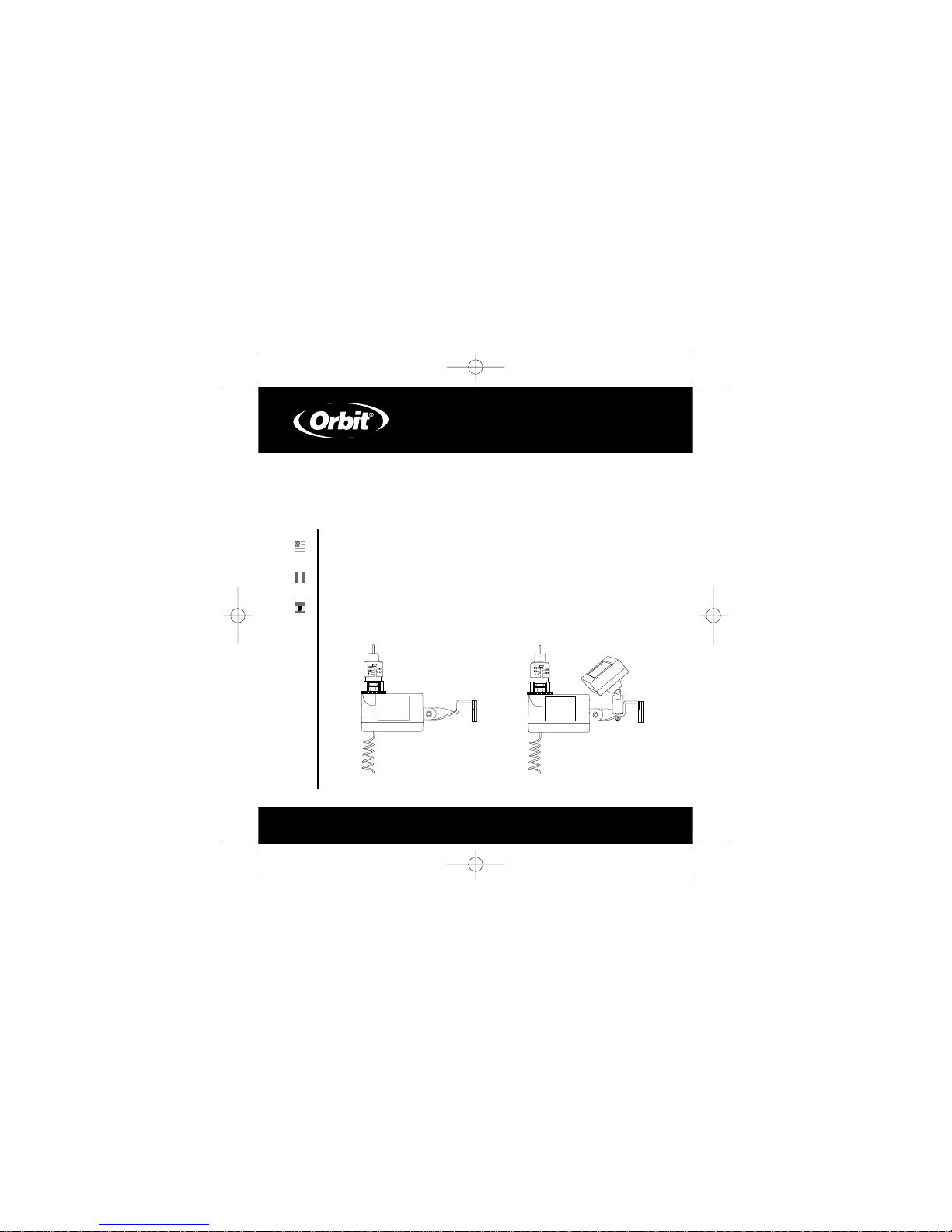
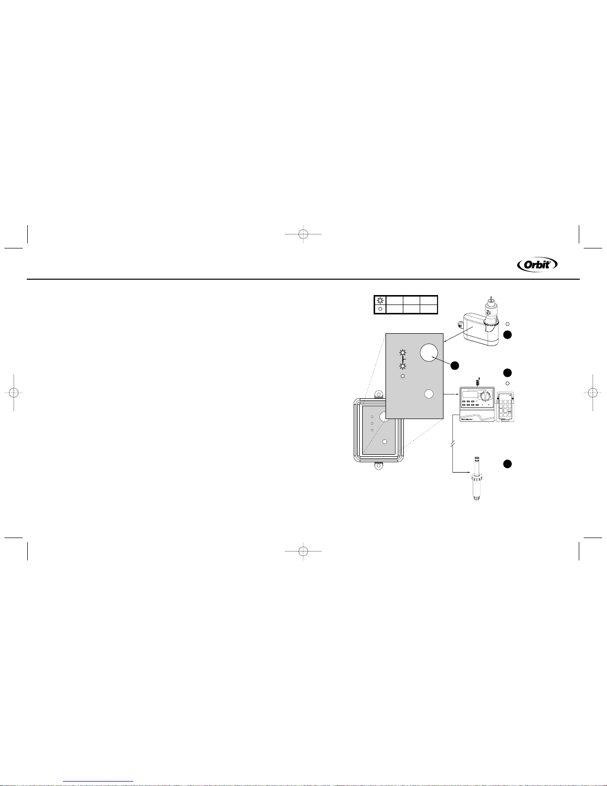
Battery Power
The Rain/Freeze sensor is powered by 2 replaceable 3V lithium batteries
(models 57071, 57271, 27681) or by a solar cell and a rechargeable battery
pack (models 57070, 57270, 27680). (See figure 1)
SECTION 1
Introduction
WTM230900 57071-24 rA.qxd 4/11/03 8:03 PM Page 2
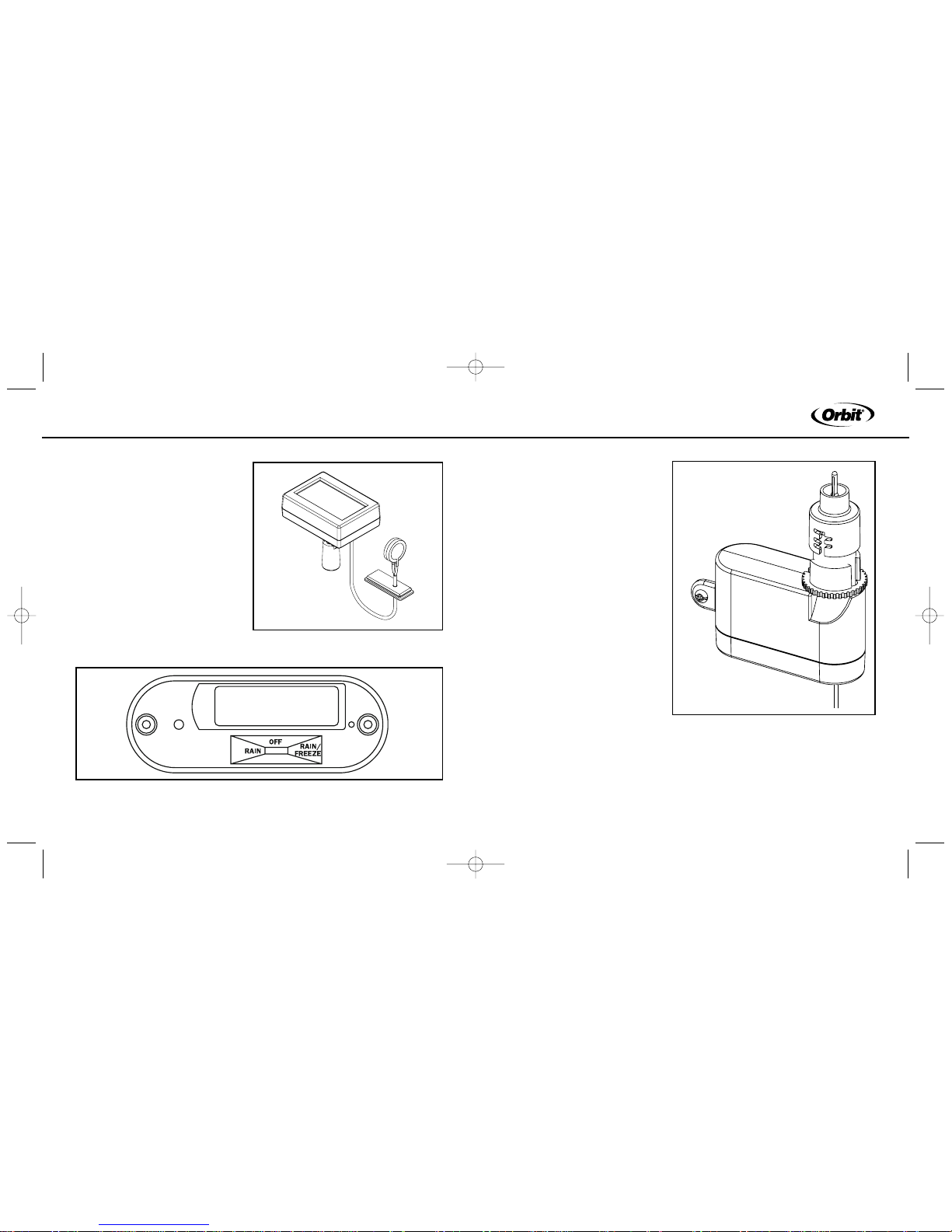
1. Manual Test Stem
Pushing downward on stem tests
transmitter communication with
the receiver.
2. Rain Fall Adjustment Cap –
Range adjustable from 1/8" to 1"
(3mm to 25mm). This setting will
prevent watering when rainfall
reaches the setting.
3. Vent Ring
An adjustable ring designed to
control the rain delay duration.
4. Communication Antenna
Transmits a wireless signal (up to
200’) to the Rain/Freeze receiver.
5. Mounting Brackets
Attach to gutter or flat surface
5
ENGLISH
4
Feature Control Switch
Located on the bottom of the transmitter,
the 3 position control switch allows you to
select Rain Sensor, Rain/Freeze Sensor
and Sensor Off (See figure 2).
Figure 2: Bottom view of Sensor/Transmitter
Figure 1: Solar cell with rechargeable battery
Battery Compartment
Figure 3: Rain/Freeze Transmitter
1
2
3
4
5
WTM230900 57071-24 rA.qxd 4/11/03 8:03 PM Page 4
7
ENGLISH
6
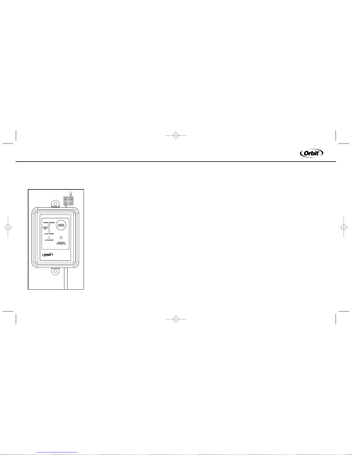
LED Panel Lights
Located on the receiver, the LED lights communicate the current status
of the sensor. (See figure 4)
6. Communication Antenna
Receives Wireless signal from the
Rain/Freeze sensor.
7.Manual Override Button
Functions in 2 ways:
1. Stop timer from watering
2. Allow watering when Rain/Freeze
sensor is active
-See Manual override (Section 4) for
additional detail
8. Sensor Override LED
Indicates when Manual Override is on (see
Manual Override above).
9. Active Sensor LED
Indicates when the rain/freeze sensor is
overriding the sprinkler timer.
10. Low Battery LED
Indicates when battery needs to be replaced.
(Only applicable to models 57071, 57271 and 27681)
6
7
8
9
10
SECTION 2
Installation Instructions
Mounting the Receiver
1. Select a Location within 6” adjacent to your sprinkler timer (receiver
may be located indoor or outdoor).
2. Mount rain/freeze receiver (antenna side up) using screws provided.
3. Extend and straighten the antenna upward.
Wiring the Receiver to Timer
Important: This sensor is designed for 24 Volt Irrigation Timers only do not
connect the receiver to 120/240 VAC. All wiring must conform to applicable
local codes. Disconnect power to the sprinkler timer (unplug timer, turn off
the appropriate circuit breaker or remove fuse) before attempting to connect
the rain sensor receiver.
The two most common wiring situations are detailed below. The green
“normal open” wire is not used in most installations. For non-standard
wiring situations, please contact our customer support hot-line.
24-Volt Solenoid Valves Only (No booster pump).
1. Remove wire terminal cover from timer
WTM230900 57071-24 rA.qxd 4/11/03 8:03 PM Page 6
9
ENGLISH
8
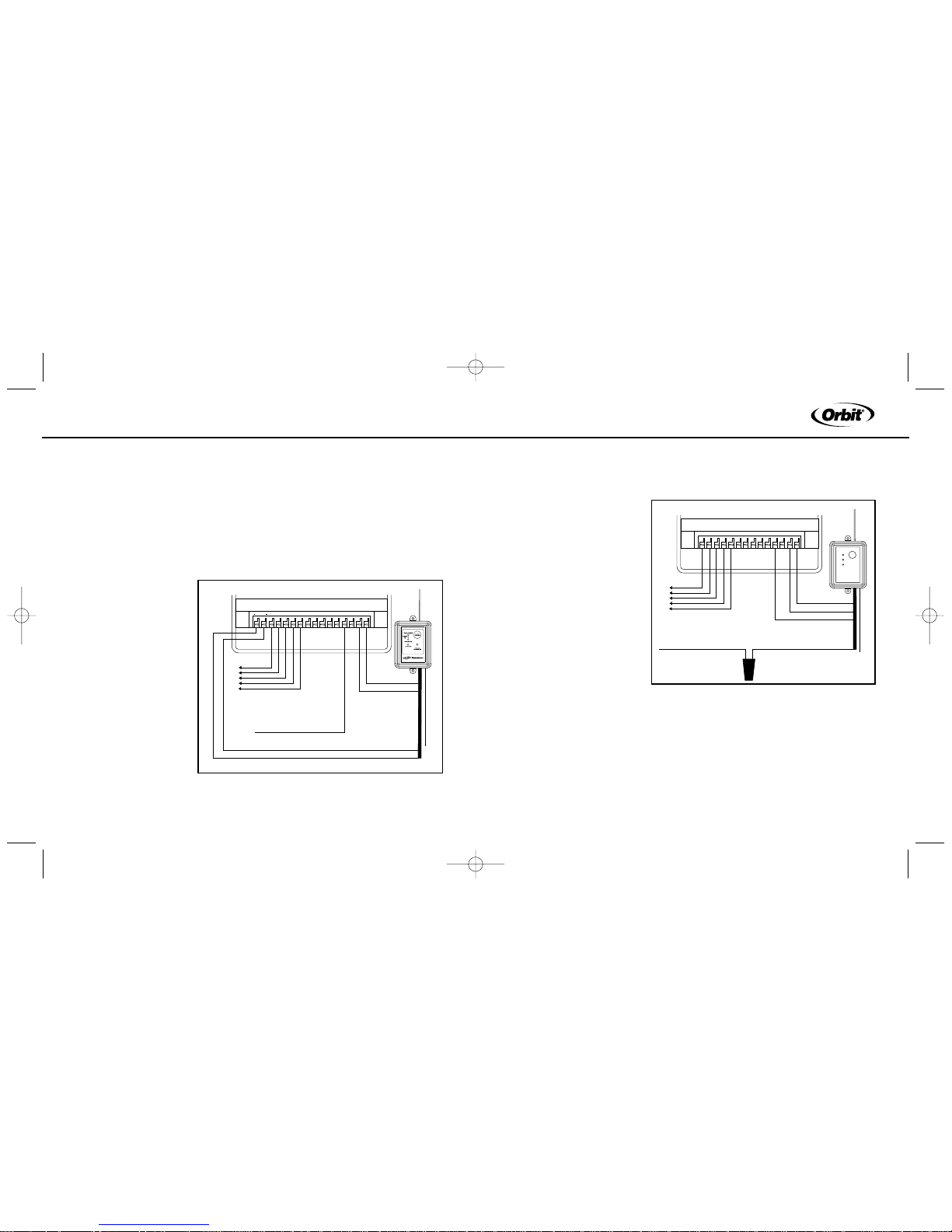
2. Check your timer for pre-installed sensor terminals. If the timer does
not have sensor terminals, proceed to step 3. If it does, take the wire from
rain/freeze receiver and connect the white (common) wire to one sensor
terminal and the yellow (normal closed) wire to the other. (see figure 5)
Skip to step 5.
3. Disconnect the common valve wire from the timer, and attach it (using a
wire nut) to the yellow
(normal closed) wire
from the rain/freeze
receiver.
(see figure 6)
4. Connect the white
(common) wire from
the rain/ freeze
receiver to the
common terminal
of the timer.
5. Connect the (2) red
“24V” wires to the 24V
terminals of the timer.
24V 24V
COM1 COM2
123456 789
PUMP
Controller / Timer
To Va lv e
Common From Valves
White
Yellow
Red
Red
Green (not connected)
SENSOR
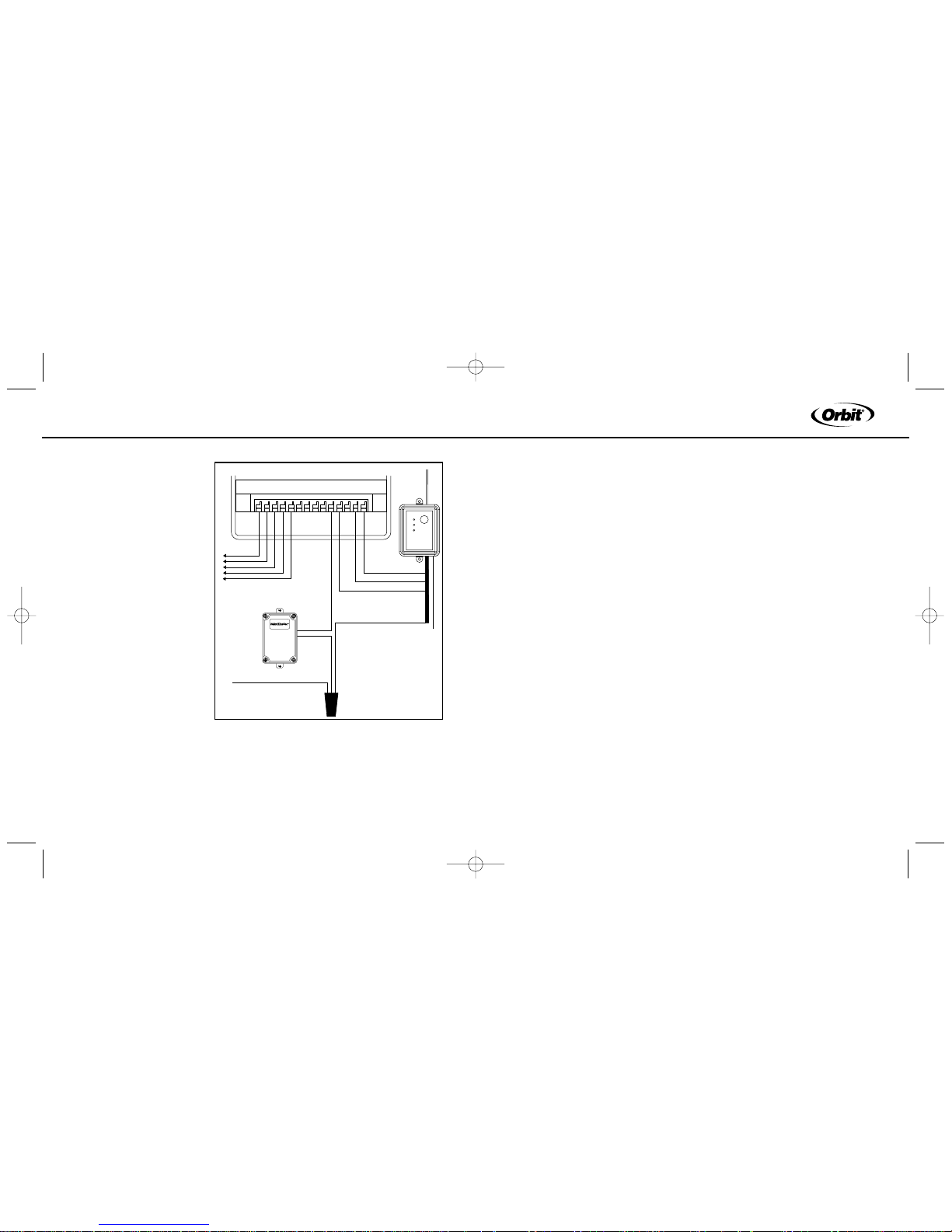
24-Volt Solenoid Valves with Booster Pump.
Note: The pump circuit output must be 24 volts in this situation; if different,
do not proceed.
1. Remove wire terminal
cover from timer.
2. Check your timer for preinstalled sensor terminals.
If the timer does not have
sensor terminals, proceed
to step. 3. If it does, take
the wire from the
rain/freeze receiver and
connect the white (common) wire to one sensor
terminal and the yellow
(normal closed) wire to the
other. (See figure5) Skip
to step 5.
3. Disconnect the common valve wire(s) from the timer and the common
wire lead of the relay that starts the pump from the common terminal of the
timer. Attach them to the yellow (normal closed) wire from the receiver,
24V 24V
COM1 COM2
123456 789
PUMP
Controller / Timer
To Va lv e
Red
Red
Green (not connected)
White
Common From Valves
Wire Nut
Yellow
Figure 6: Wiring Sprinkler Timer with out Sensor
Figure 5: Wiring Sprinkler Timer with Sensor terminals and
with out booster pump.
WTM230900 57071-24 rA.qxd 4/11/03 8:03 PM Page 8
11
ENGLISH
10
using a wire nut. (See
figure 7).
4. Connect the white
(common) wire from the
rain/freeze receiver to
the common terminal on
the timer.
5. Connect the (2) red
“24V” wires to the 24V
terminals of the timer.
SECTION 3
Operation
Checks
Verify Correct Wiring
Select a sprinkler station/
zone that is visible and in
reach of the Rain/Freeze
receiver and sprinkler timer. After Manually activating the station/zone, on
the sprinkler timer, press the”Manual Override” button on the receiver. The
top light should indicate that the system is being overridden. If the light
24V 24V
COM1 COM2
12345 6789
PUMP
Controller / Timer
To Valve
Red
Red
Green (not connected)
White
Common From Valves
Wire Nut
Yellow
Pump
Start
Relay
does not illuminate, check the red wire connections. If the light is illuminated then the zone watering (and the pump, if installed) should shut off. If the
zone continues to water check the white and yellow (or green) wire connections.
Verify Communication between the Transmitter and Receiver
Verify that the Control Switch, located on the bottom of the transmitter, is
set on either the “Rain” or “Rain/Freeze” position. Next, press the manual
test stem on the transmitter until you hear a light click. While holding the
test stem down verify that the receiver “Sensor Active” light is illuminated.
If the light is illuminated, the communication is set. If the light does not illuminate, press and hold the “Transmitter Program” button for at least two
seconds. Once all three lights are illuminated, press the manual test stem
repeatedly until the three lights start flashing. When the lights stop flashing
press the manual test stem again, the “Sensor Active” light should illuminate.
If problems persist check your wiring or call our technical support group.
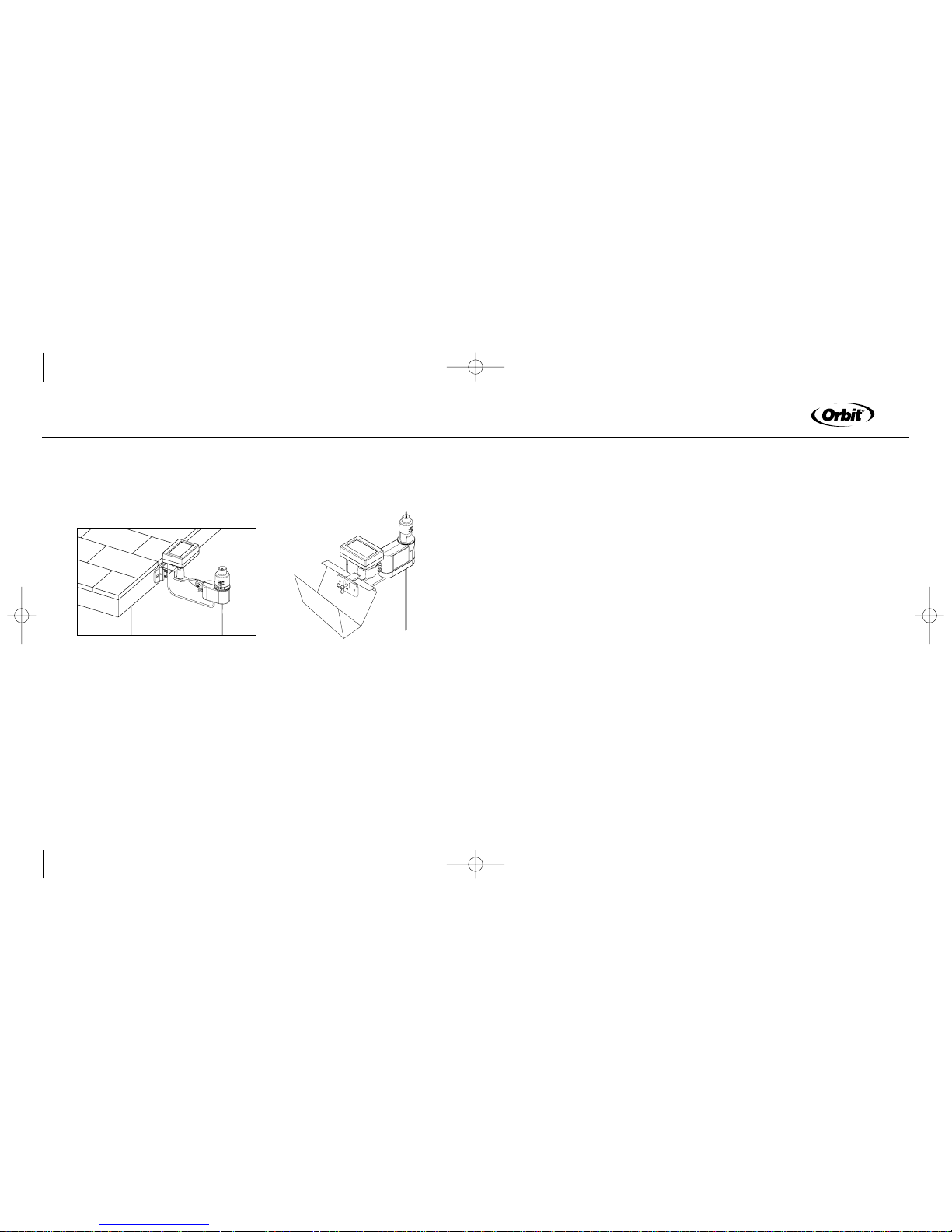
Mounting the Transmitter
Mount the rain/freeze sensor to a gutter with the provided thumb screw, or
to a flat surface, with provided screws, where it will be exposed to direct,
unobstructed rainfall (but away from sprinkler spray). The test stem must
be upright. For solar powered models the transmitter must be mounted so
that the solar cell can receive direct, unobstructed sunlight. (See figure 8)
Figure 7: Wiring Sprinkler timer with booster pump but
with out Sensor terminals
WTM230900 57071-24 rA.qxd 4/11/03 8:03 PM Page 10
13
ENGLISH
12
Note: The distance that the transmitter and receiver will operate at is
approximately 200 feet line of sight. This distance may be affected by
obstacles such as walls, automobiles, metal siding, etc.
Figure 8: Attaching Sensor/Transmitter to gutter or flat surface
Hints for Mounting:
1. Mount the transmitter in the highest possible position where rain can fall
directly upon the rain sensor.
2. The transmitter mounting location will affect the reset rate, the amount
of time it takes the rain sensor to dry out sufficiently for the sprinkler system to reactivate. For example, mounting the rain sensor on a very sunny,
southeastern end of a house may cause the rain sensor to dry out sooner
than desired. Similarly, mounting on the northern end of a building with
constant shade may keep the rain sensor from drying out at all. Some
experimentation with the “vent ring” (described in the “Adjustments and
Operation” section 4) will usually yield satisfactory results.
3. Always remember the solar cell models need to be mounted in direct,
unobstructed sunlight.
SECTION 4
Adjustments and Operation
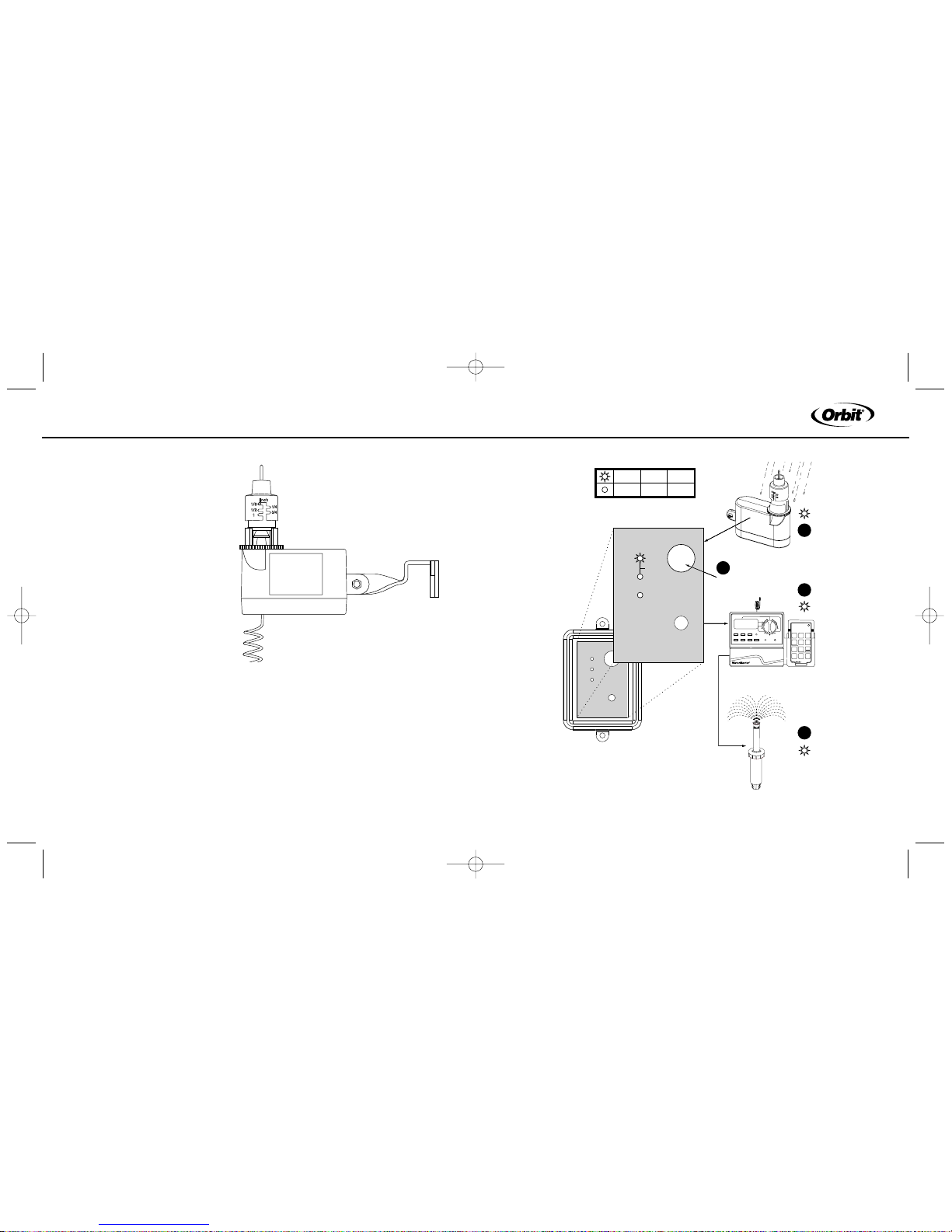
Rain Sensor
The rain sensor can keep the irrigation system from starting or continuing
after rainfall quantities of 1/8", 1/4", 1/2", 3/4", or 1". We recommend that
the sensor be set at the 1/8" setting. To adjust to the desired quantity of
rainfall, rotate the cap on the switch housing so that the pins are located
in the proper slots. Do not forcibly twist the cap as this might break the pins.
The time that it takes the rain sensor to reset for normal sprinkler operation
after the rain has stopped is determined by weather conditions (wind, sunlight, humidity, etc.). These conditions will determine how fast the hygroscopic discs dry out, and since the landscape is also experiencing the
same conditions, their respective drying rates will roughly parallel each
other. There is an adjustment capability on the rain sensor that will slow
down the rest rate. By turning the “vent ring” to completely or partially
cover the ventilation holes, the hygroscopic discs will dry more slowly. This
adjustment can compensate for an “overly sunny” installation location or
WTM230900 57071-24 rA.qxd 4/11/03 8:03 PM Page 12
15
ENGLISH
14
peculiar soil conditions.
Experimenting with the vent
rings will best determine the
ideal vent setting. (See figure 9)
Freeze Sensor
The temperature at which the
freeze sensor is activated is
37°F ±2° (3°C ±1°) and is not
adjustable. The freeze sensor
feature can be bypassed by
moving the switch (located on
the bottom of the rain/freeze
sensor) to the “Rain” position.
Manual Override
The Manual Override button
can be used in 2 functions:
"
Running the sprinkler timer when Rain/Freeze sensor is active
(Deactivating the sensor)
"
To stop timer from watering (Deactivating Sensor and Timer)
Running the sprinkler timer when Rain/Freeze sensor is active
(see figure 10)
1. Make sure “Active Sensor” is the only LED illuminated (on the Rain/
Freeze receiver)
Figure 10: Running the sprinkler timer when Rain/Freeze sensor is active
ON
ON
10 min
10 min
ON
ON
30 min
30 min
ON
ON
60 min
60 min
ON
ON
2 min
2 min
ALL
ALL
Stations
Stations
4 5 6
1 2 3
Remote
Control
Transmitter
6 STATION MODEL 57036
OFF
OFF
Auto Resume
Auto Resume
MODEL 570166 STATION TIMER/REMOTE
INTERVAL
ODD
EVEN
1
2
3
4
S
T
A
R
T
P
R
O
G
R
A
M
M
T
W
T
F
S
S
DMY
W
A
T
E
R
IN
G
IN
T
E
R
V
A
L
S
TATIO
N /
DUR
ATIO
N
AUTO
OFF
TIME/
DATE
WATERING
DAYS
STATION /
DURATION
(A)
(B)
123456
STATIONS
RESET
MANUAL
CLEAR NEXT
–
+
ENTER
RAIN DELAY
2
n
d
S
T
A
R
T
T
IM
E
S
START
TIMES
RF ACTIVE
TRANSMITTER
PROGRAM
H
a
r
d
T
o
p
H
a
r
d
T
o
p
Sensor Override
Active Sensor
Irrigation
system off
Low Battery
Manual
Override
Transmitter
Program
1
3
4
2
ON
OFF
SURDEEN
DEL
Figure 9: Rain and vent ring adjustments
WTM230900 57071-24 rA.qxd 4/11/03 8:03 PM Page 14
17
ENGLISH
16
2. Push the “Manual Override” button – “Sensor Override” will illuminate
and “Active Sensor” LED will turn off.
3. To restore Rain/Freeze sensor function Push “Manual Override” again –
“Sensor Override” LED will no longer illuminate.
Stop Sprinkler Timer from Watering(see figure 11)
1. Make sure “Active Sensor” and/or “Sensor Override” is/are not illuminated
(on the Rain/Freeze receiver)
Important: If “Active Sensor” is illuminated, do not push “Manual
Override” (this will engage the function above). If you need to shut
your irrigation system down, turn your timer to the off position.
2. Push the “Manual Override” button - Both “Sensor Override and “Active
Sensor” will illuminate (on the Rain/Freeze receiver).
3. To restore sprinkler timer function, push “Manual Override” again. –
“Sensor Override” will no longer illuminate.
Figure 11: To stop timer from watering
ON
ON
10 min
10 min
ON
ON
30 min
30 min
ON
ON
60 min
60 min
ON
ON
2 min
2 min
ALL
ALL
Stations
Stations
4 5 6
1 2 3
Remote
Control
Transmitter
6 STATION MODEL 57036
OFF
OFF
Auto Resume
Auto Resume
MODEL 570166 STATION TIMER/REMOTE
INTERVAL
ODD
EVEN
1
2
3
4
S
T
A
R
T
P
R
O
G
R
A
M
M
T
W
T
F
S
S
DMY
W
A
T
E
R
IN
G
IN
T
E
R
V
A
L
STATION
/
DUR
ATIO
N
AUTO
OFF
TIME/
DATE
WATERING
DAYS
STATION /
DURATION
(A)
(B)
123456
STATIONS
RESET
MANUAL
CLEAR NEXT
–
+
ENTER
RAIN DELAY
2
n
d
S
T
A
R
T
T
IM
E
S
START
TIMES
RF ACTIVE
TRANSMITTER
PROGRAM
H
a
r
d
T
o
p
H
a
r
d
T
o
p
ON
OFF
SURDEEN
DEL
Sensor Override
Active Sensor
Irrigation
system off
Low Battery
Manual
Override
Transmitter
Program
1
3
4
2
WTM230900 57071-24 rA.qxd 4/11/03 8:03 PM Page 16
19
ENGLISH
18
Maintenance
For solar models there is no required maintenance; the battery is continually
powered through the solar-trickle charge. For all other models the two
lithium 3V batteries (CR2032) will need to be changed as needed. There is
a low battery indicator light on the receiver that tells you when you need to
change the battery. To change the batteries, remove the black rubber cover
from underneath the sensor/transmitter. The battery mount should drop
down, attached with a wire. Replace both batteries, making sure the + side
of the batteries point to the + indicated on the mount. Insert the battery
mount and replace cover, making sure it’s seated properly.
Neither the rain or freeze sensor needs to be removed or covered during
the winter. All parts are easily replaceable if they become damaged or
lost. The spindle assembly is designed to stay with the cap. Do not pull
them apart.
SECTION 5
Troubleshooting
Follow these simple checks before replacing your rain/freeze sensor:
System will not come on at all:
A. Check to see that the rain sensor discs are dry and the switch “clicks”
on and off freely by pressing the top of the spindle.
B. Check the feature control switch to make sure it is switched to the
“rain” setting or the “rain/freeze” setting.
C. Toggle the manual override switch on the receiver to change status.
D. If you have a timer with built-in sensor terminals there is usually a
bypass switch located near the terminals, check that the switch is set
to “ON.”
E. Check that the temperature is at least 39°F (4°C) or higher.
System will not shut off even after heavy rainfall:
A. Check wiring for correct installation (See “Operation Checks: Verify
Correct Wiring”).
B. Check sensitivity setting on rain sensor, and move the cap to a more sensitive setting. The rain sensor is an accurate rain gauge and can be verified by
setting up a “tube” type rain gauge in the same vicinity and making periodic
readings.
C. Check for obstructions to rainfall such as overhangs, trees, or walls.
D. Check the batteries.
E. Ensure that the solar cell is exposed to direct, unobstructed sunlight.
WTM230900 57071-24 rA.qxd 4/11/03 8:03 PM Page 18
 Loading...