

Page 1

Layout Guide
Easy, step-by-step,
Easy, step-by-step,
underground sprinkler
underground sprinkler
system layout guide
system layout guide
FREE SPRINKLER
SYSTEM DESIGN
See page 5 for details
Page 2

Planning & Design
Water
Meter
Compression
Tee
3/4” Water Service
Line for House
Flow
Main Sprinkler
Shut-Off
Pre-Assembled
Swing-Joint
L
Spring-Loaded Pop-Up
with Adjustable Nozzle
2
WHY INSTALL AN UNDERGROUND IRRIGATION SYSTEM?
• Conserve Water & Money – Reduce over-watering and water when evaporation
levels are low.
Time
e
v
Sa
•
•
Incr
ease Property Value
more attractive.
Eliminate Yard Clutter – Eliminate the ugly tangle and yellow marks left by unsightly
•
garden hose.
CHECK LOCAL CODES
– Enjoy a beautiful yard and spend more time doing the things you lik
– Greener
, thicker lawns, shrubs and trees, make your property
e.
1
2
Water District
Call your local water district for requirements concerning permits, plumbers, backflow prevention
and pipe requirements.
Sprinkler System Layout & Installation Guide
Page 3

Planning & Design
Main Sprinkler
Line 1"
Anti-Siphon
Device
Sprinkler
Timer
Sprinkler
Wire
Header
Line 1"
Lateral Sprinkler
Line 3/4"
Valve
Manifold
Common Questions To Ask Your Water District:
Is a permit required?
•
• Is a licensed plumber required for connecting to the main water supply?
▫Yes ▫ No
What type of backflow prevention device is required?
•
▫ Double Check ▫ Pressure Vacuum Breaker
▫ Automatic Anti-siphon Valve ▫ Dual Check Valve
• Climate: Will pipes freeze in my area?
reezing
▫ F
• How deep should I bury my pipes?
Pipe Depth ___________
• What type of pipe is required (or recommended) for my area?
Pipe type: ____________
▫ Non Freezing
▫Y
es
▫ No
Utility Companies
Before digging, contact your local gas, power, telephone, and cable companies to mark
underground cables and pipelines on your proper
▫ Gas ▫ Power ▫ Other _____________
▫ Phone ▫TV & Internet cables
ty, such as:
Sprinkler System Layout & Installation Guide
3
Page 4

Planning & Design
200 0
180 20
160 40
1
40 60
120 80
100
psi
O
rbit
2
0
0
0
1
8
0
2
0
1
6
0
4
0
1
4
0
6
0
1
2
0
8
0
1
0
0
psi
Orb
it
200 0
180 20
160 40
1
40 60
120 80
100
psi
O
rbit
2
0
0
0
1
8
0
2
0
1
6
0
4
0
1
4
0
6
0
1
2
0
8
0
1
0
0
psi
Orb
it
DETERMINE SIZE OF SERVICE LINE
Length of string 2" 2-3/4" 3-1/4" 3-1/2" 4-1/4"
Copper pipe size 1/2" 1"
PVC or galvanized pipe size 1/2" 3/4" 1"
3/4"
WATE R PRESSURE (PSI)
35 LB. 40 LB. 45 LB. 50 LB. 55 LB. 60 LB. 65 LB. 70 LB. 75 LB.
MAIN
LINE
SIZE
1/2"
3.5 5.0 6.0 6.5 7.0 7.5 8.0 9.0 9.5
3/4"
7.5 9.0 10.0 12.0 13.0 14.0 15.0 16.0 17.5
1"
10.0 11.5 13.5
15.0
16.0 17.5 18.5 20.0 21.0
MEASURE WATER FLOW
You need to determine the available water flow for your sprinkler system so you'll know
ow many sprinkler heads can run at one time. Water flow is measured in gallons per minute
h
or GPM.
Measure Your Water Pressure
• Attach an Orbit®pressure gauge (part #
53020, 91130) to an unregulated outside
faucet*. Unregulated means a line without
a pressure regulator.
• Open the faucet and record the reading
on the gauge. No water should be running
during the test.
PSI _________
Measure the Main Water Service Line
• Wrap a piece of string around your main
ater service line then measure the length
w
of the string.
• Use the table to convert the string length
to pipe size (diameter).
3
Note: The main water service line is the pipe that runs from
the water meter to the house. If you're connecting to a line
other than the main line, measure the line that you will be
connecting to.
Pipe Size _________
GPM Capacity ___________
* If an unregulated faucet is unavailable, call the local water district for an estimated PSI.
ystem Capacity
S
Use the main
line pipe size
and pressure
(PSI) taken to
determine the
gallons per
minute (GPM)
capacity of your
system.
4
Important: If your water pressure exceeds 80 PSI, use a pressure reducer
. Excessive pressure may damage system.
Sprinkler System Layout & Installation Guide
Page 5

Planning & Design
D
RIVEWAY
SHRUBS
PATIO
TREE
T
REE
G
RASS
GRASS
F
LOWERS
W
ATER
METER
70'
73'
4
0'
20'
1
0'
7'
14'
13'
18'
40'
40'
10'
10'
48'
10'
12'
7
3'
STOP
MEASURE & DRAW PROPERTY
Measure your property and create a top down view on graph paper (supplied in this guide).
ake the drawing to scale. For example, each one-inch square represents 10 feet on the graph
M
paper, or each small square = 1 foot.
Draw Property
to Scale.
Include:
Buildings, sidewalks, patios,
driveways and trees
Label:
Grass, flower beds and
water meter
location
LET ORBIT®DESIGN YOUR SPRINKLER SYSTEM
Instead of continuing on to the next section,
www.orbitonline.com and use the free
go to
sprinkler system design program.
4
TIME SAVING
TIP!
What y
SELECT HEADS
elect sprinkler heads you would lik
S
ou receive:
• Detailed color-coded drawings with:
▪ Sprinkler placement and spray patterns
▪ Layouts of individual sprinkler zones/stations
▪ Valve and sprinkler pipe placement.
• Step by step assembly instructions.
• Detailed parts list for PVC or Poly-Pipe systems.
• Quick turn around – Completed in about 2 days.
e to use for eac
h area and mak
e a note of eac
5
h type on
your drawing.
ype for Each Section
ea Spr
Ar
T
inklers
s, shrubs, and ground cover
our Products) to determine the best sprinkler for your yard.
Select Head
Sprinklers are generally divided into three categories:
•
Large Area Sprinklers
Areas larger than 25' x 25'
• Medium Area Sprinklers
Areas smaller than 25' x 25'
Small
•
Areas with flower
Note: Refer to page 22 (Selecting Y
Sprinkler System Layout & Installation Guide
5
Page 6

Planning & Design
DRIVEWAY
PATIO
TREE
TREE
Large
Voyager II
®
Spring-Loaded
Pop-Up
Medium
Small
Small
Spring-Loaded Pop-Up
Medium
Select Heads For
E
ach Area
Our example uses:
Voyager II
•
®
n the back yard
i
• Spring-Loaded Pop-Up (with
adjustable nozzle) in the front
and side yard
• Mushroom bubblers in the
front flower areas
Large Area Heads
For large open areas such as backyards and play areas. Space heads 15' to 45' apart
(depending on sprinkler type).
Gear Drive – Voyager II®and Saturn III
•
- Easy to adjust
roduces a smooth quiet rotating spray
- P
- Closed case design resists clogging from grit, sand and heavy grasses
• Impact (Satellite®and 1⁄2" Brass Impact)
- Simple and reliable flow-through design that utilizes an efficient impact mechanism
®
6
Voyager II®– Spaced 20' to 40' Saturn III®– Spaced 15' to 30'
ea Heads
Medium
Ar
Satellite®– Spaced 25' to 45'
Commonly used in front and side yards.
Spring-L
•
oaded Pop-Up with adjustable pattern
- Easy to adjust pattern 25˚ - 360˚
• Spring-Loaded Pop-Up with fixed pattern
Medium Area Heads
Pop-up heads & Flush heads
Spacing: 10 to 15 feet
- Available in Full, 1/2, 1/4 and strip pattern nozzle
Small
Area Heads
Commonly used for flooding flower beds and ground cover
or to spot water trees and shrubs.
Small Area Heads
Stream & Bubbler heads
Spacing: 3 to 5 feet
Mushroom Bubbler II
•
- Adjustable flow
Note: Orbit®DripMaster®is a water saving alternative to small area heads. Go to
www.orbitonline.com for more information.
™
Sprinkler System Layout & Installation Guide
Page 7

Planning & Design
Sidewalk
PLAN HEAD PLACEMENT
Head to Head Coverage
Proper sprinkler placement allows even watering and
reduces dry patches.
Proper placement requires:
• Head to head coverage: Each sprinkler should spray
to the head beside and across it.
• Equal spacing between heads: Permits uniform water
distribution.
Placement Example: Good
• Good Overlap
• Head to head coverage
Placement Example:
There is not enough overlap. The center is not
getting water.
• Not enough overlap
• No coverage in center
Bad
6
Evenly space strip heads on narrow sections.
row Str
Nar
On narrow strips of grass use strip pattern
spray heads and space them evenly apart.
These heads may be used for narrow
strips up to 4 feet wide.
ips
Place Heads in Corners
• Begin by placing a sprinkler in
each corner on your drawing.
• Use a compass to draw the
spray pattern.
Note: Use chart 2 on page 20 to obtain spray
distance.
Sprinkler System Layout & Installation Guide
7
Page 8

Planning & Design
Large
Add Heads and
Adjust Spacing
• Add sprinklers along
the sides or center to
increase coverage.
CREATING WATERING ZONES OR STATIONS
A watering zone or station consists of a group of sprinklers attached to one valve.
The number of heads per zone will be determined in this section.
Purpose of Zones
Zones are designed to:
• Maintain adequate water flow for optimal spray coverage (Avoid dry patches)
• Separate areas based on watering requirements
- Shade vs. Full Sun Areas
- Lawn vs. Shrubs
Important:
• Do not mix sprinkler types in the same zone (e.g. Gear Drive, Impacts, Pop-Ups and Bubblers)
• Do not exceed the maximum sprinkler heads recommended per zone
• Use the recommended pipe size in this guide. Smaller diameter pipe will decrease the water flow.
Group Heads of Same Type in the Same Area
Starting with large area heads, use the following
example as a guide.
• Identify all large area heads on
your drawing.
Divide Large Area Heads into Zones
7
8
Lar
ea heads circled
e ar
g
TEP 1:
S
Use the following information (collected earlier) to
determine zone capacity:
• Main Line Size
W
•
• Large area head selected
Use Orbit’s
to determine the maximum heads per zone for your
sprinkler system.
Maximum Heads P
ressure (PSI)
ater P
®
Quick Reference (Chart 1, Page 20)
er Zone
Sprinkler System Layout & Installation Guide
Page 9

Planning & Design
WATER PRESSURE (PSI)
SCH.
40
PVC
Gear Drive
30 PSI 40 PSI 50 PSI 60 PSI
12
2223
3
4
Q
UICK REFERENCE – MAXIMUM HEADS PER ZONE ESTIMATES
MAIN
LINE
SIZE
V
oyager II
®
Saturn III
®
Example – We have determined that our home
has a “Main Line” size of 3/4” with
a “Static Water Pressure” of 60 psi. Based on
this information, and using the Quick
Reference, we see that we cannot use
more than three Voyager II
®
sprinklers in
the same zone.
STEP 2: Identifying Sprinklers in a Zone
Begin grouping large area heads, ensure you do not exceed your “Maximum Heads per zone number.”
Example – Since we determined (in our example above) that 3 Voyager II®heads
is the maximum zone capacity, we grouped all large area heads into 2 zones.
Step 3:
Medium and Small Area Head Zones
Repeat steps 1 & 2 to determine and identify zones for Medium Areas Heads. Repeat again for
Small Area Heads.
Step 4: Number Each Zone
• Assign a number to each zone.
Sprinkler System Layout & Installation Guide
9
Page 10
Planning & Design
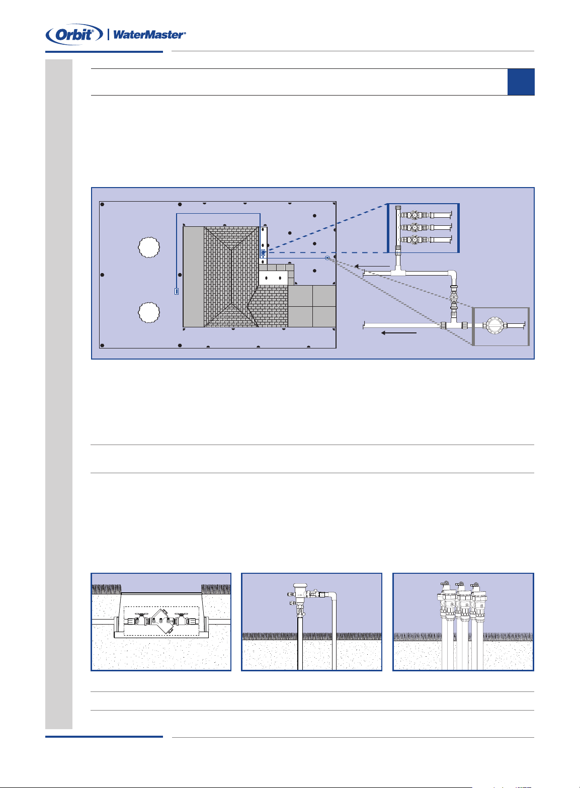
WATER
METER
MAIN SPRINKLER
S
HUT-OFF VALVE
TO HOUSE
MAIN LINE TO
R
EAR MANIFOLD
W
ATER METER
M
AIN LINE
FRONT
V
ALVE
MANIFOLD
PLAN VALVE PLACEMENT
You'll need to select a location for your main shut-off valve and the best location for the
prinkler valve manifold.
s
Main Shut-Off Valve
he Main Sprinkler Shut-Off valve is the valve that shuts off water to the entire sprinkler
T
ystem. Connection to the main water supply is “downstream” of your water meter. Mark
s
the location on your plan.
8
Valve Manifold Location
One valve will be used for each zone. Valves that are grouped together are called a manifold.
It’s common to install one manifold in the front yard and one in back.
Mark the Location on Your Plan
Tip: The valve manifold(s) should be installed in an accessible location, away from heavy foot traffic, where it is easy to operate
and service. It's also a good idea to locate the manifold on elevated ground, to avoid water accumulating around the valves.
Plan Backflow Prevention
A backflow prevention device is used to stop foreign material from siphoning back into the
main water supply. The local code information you gathered from your water district should
include the type of device to install and where and how it should be installed. Plan a location
for your backflow prevention device and draw it on your layout.
ee common types
Thr
Double Check
Note: For certain Canadian areas Dual Check Valves are used
Pressure Vacuum Breaker
Automatic Anti-Siphon V
alve
10
Sprinkler System Layout & Installation Guide
Page 11
Planning & Design
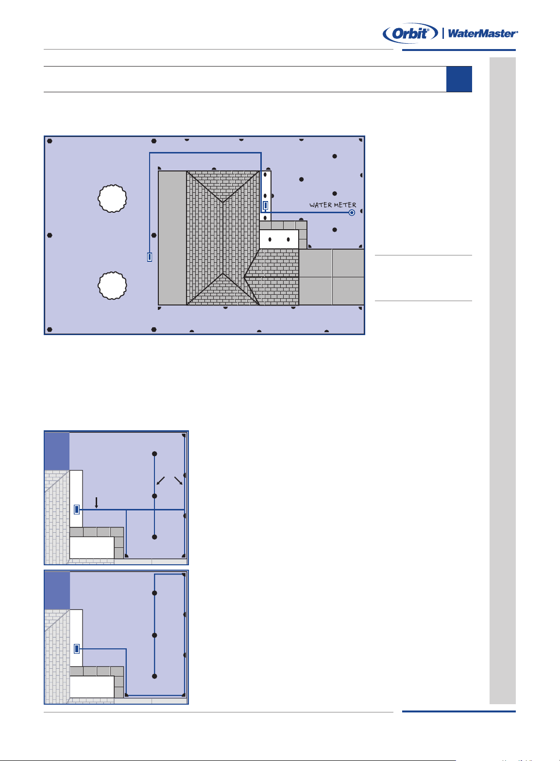
Header
Lateral
DIAGRAM PIPE LAYOUT
You need to plan and draw the layout for your main sprinkler line and lines for each zone.
Main Sprinkler Line
Draw the Main
Sprinkler Line
Route
Use a direct route
to draw the main
sprinkler line from
the main shut-off
valve to the front
and back yard
manifolds.
mportant: Your main
I
prinkler line should be
s
1 size larger than the
water main supply line.
Header and Later
Header lines – Attaches to a valve and supplies water to the lateral lines
• Do not use pipe smaller than 1"
• Do not attach sprinklers to this line
al Lines Guidelines
9
Lateral lines – Pipe that branches off from the header line and supply water to the sprinkler heads
• Do not use pipe smaller than 3/4"
Good Layout Example
This is a good layout because the water is evenly distributed
between the lateral lines and individual sprinklers.
Bad Layout Example
This is a bad layout because there is no header line. The
sprinkler heads, located at the end of the line, will have less
water pressure than the heads located closer to the valve.
Sprinkler System Layout & Installation Guide
11
Page 12
Planning & Design
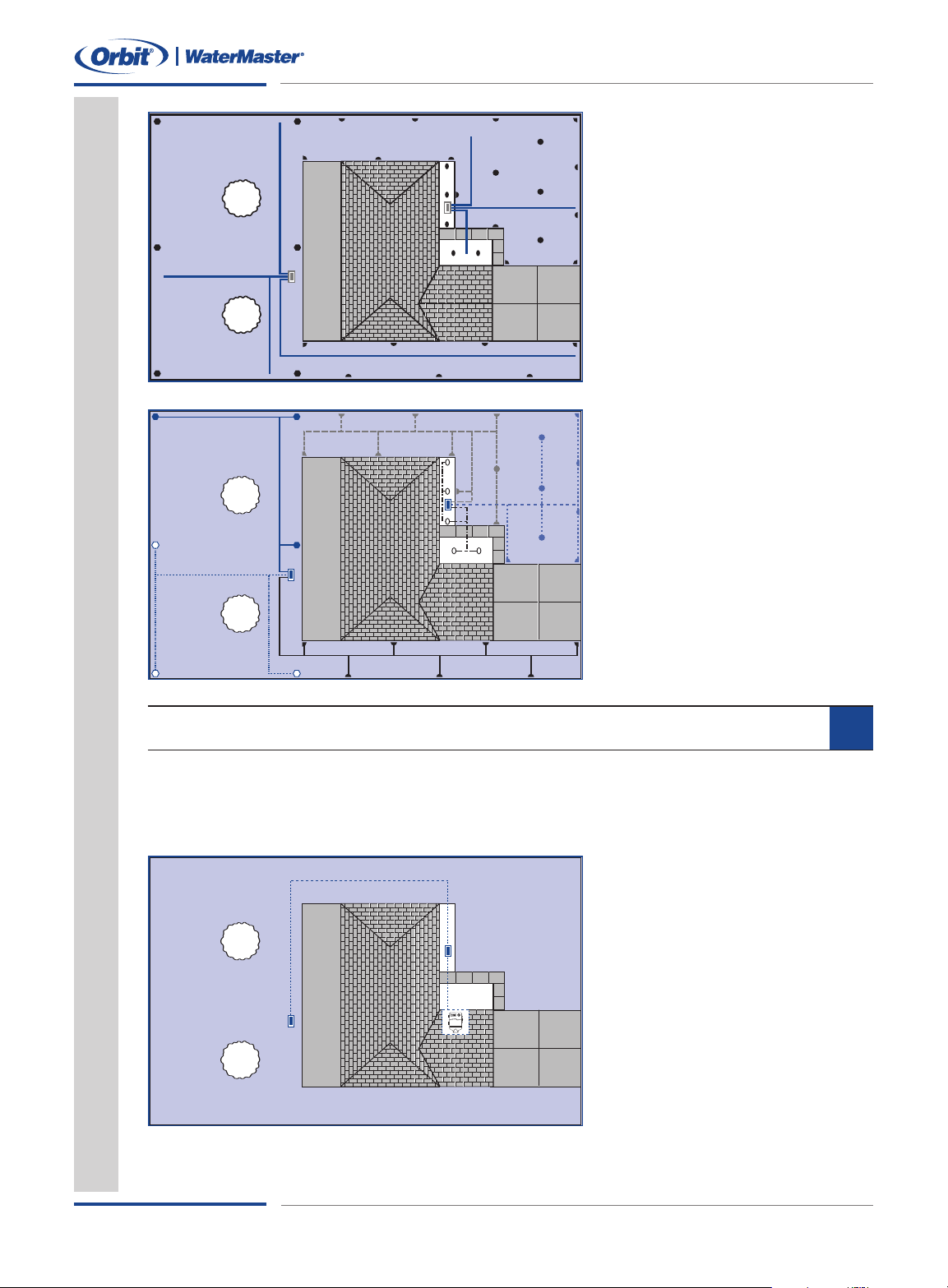
SPRINKLER WIRE
TIMER
Header Line
Draw a header line from the manifold to each zone. Header lines will
be intersected with lateral lines.
prinkler heads should not be
S
nstalled on this line.
i
Use 1" Pipe
Lateral Lines
Draw lateral lines that connect the
header line to sprinkler heads.
These lines should be branching,
not circular.
Use 3/4" pipe
PLAN TIMER LOCATION
Select a location near a power source and where it's easy to access. You'll need to be able to
run sprinkler wire to each valve. If you select a location outside, the timer should be made for
outdoor mounting or protected with a weather resistant box.
10
Timer Placement & Sprinkler
Wire Route
• Mark the planned location for the
sprinkler timer
• Draw the route the sprinkler wire
will use to connect the timer to the
front and rear manifolds
12
Sprinkler System Layout & Installation Guide
Page 13

Planning & Design
System Layout
Graph Paper
Helpful Tools
Planning
______ 50' or 100' Tape Measure ______ Compass
______ P
______ Orbit
Sprinkler System Layout & Installation Guide
encil
®
Pressure Gauge ______ String
______ R
uler
G1
Page 14

L
00
1
0
9
0
8
70
ayout Graph Paper
60
50
40
30
20
10
0
10 20 30 40 50 60 7
Page 15

G
raph Scale
= 1/10” or 1’
= 1” or 10’
00
10
1
20
1
30
1
40
1
Page 16

Installing Your
Sprinkler System
Planning & Design
G4
Helpful Tools
Installation
______ Ground Paint ______ Orbit®Sprinkler Flags
______ Sho
______ Screw Driver ______ Adjustable Pliers
______ Pipe Wrench ______ Hacksaw
______ Wire Cut
vel
ter/Striper
______ Orbit
______ Thread Seal Tape
®
Pipe Cut
ting
ool
T
Sprinkler System Layout & Installation Guide
Page 17
Installation
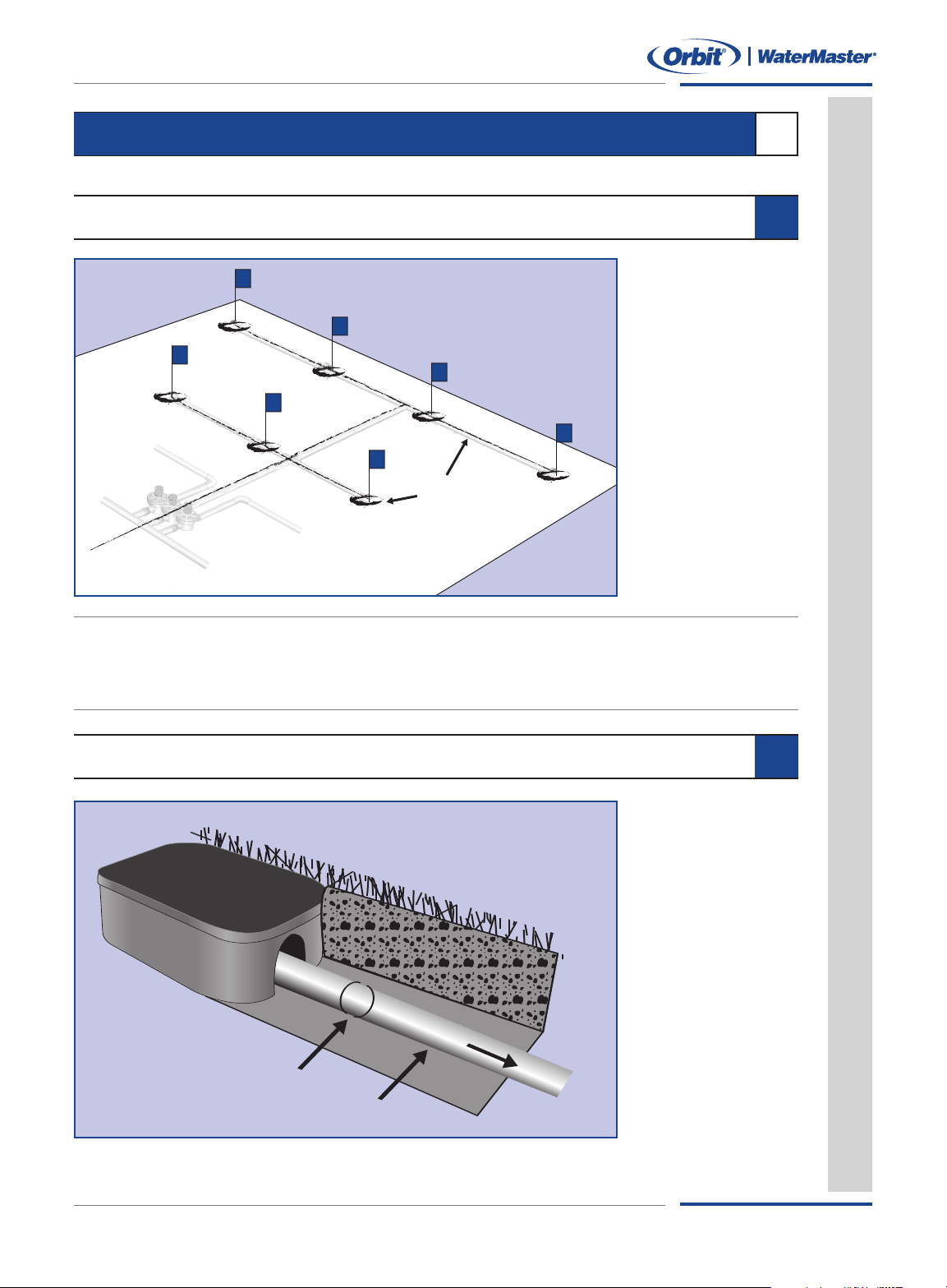
Painted Lines
Water Meter and Main Shut-Off
Connect Here for
Main Sprinkler Line
Flo
w
Water Service
Line for House
INSTALLATION
This section will show you how to install your sprinkler system.
SYSTEM LAYOUT
1
2
Marking Head and
Pipe Location
Begin by marking
the entire layout
®
• Use Orbit
kler flags to mark
each head.
• Use ground paint to
mark where sprinkler pipes will run.
sprin-
Important:
• Refer to your local code information for any regulations about connecting to the water main.
• Before digging, contact utility companies and have them mark utility lines.
• Obtain permits (if required).
• Always use gloves and safety goggles when installing.
CONNECT TO W
ATER MAIN
3
Dig Access Hole
Dig to expose the
.
1
water service line
(downstream from
the meter).
2. Shut off the main
water supply
(located next to
the meter).
3.
Open a faucet to
relieve pressure
in the pipes.
Sprinkler System Layout & Installation Guide
13
Page 18
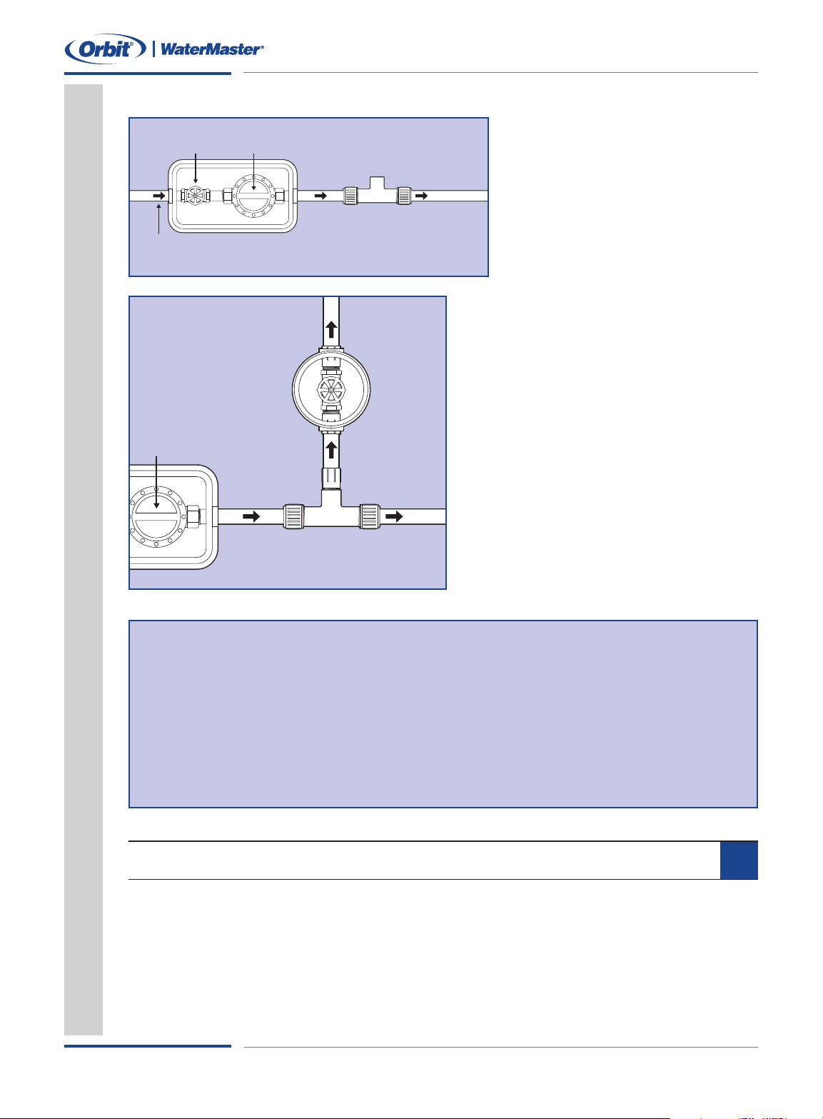
Connect to Main Line
Water Meter
Water Service Line
Slip Joint Tee To House
Shut–Off Valve
Water Meter
Pipe
Nipple
Slip Joint Tee
Main Sprinkler Line
System
Shut–Off
Valve
Installation
I
nstall a Slip Compression Tee
Clean off the water service pipe
•
downstream from meter).
(
• Cut out a section of pipe – half the
length of the tee.
• Install nuts and washers on each
side of the pipe.
• Insert the slip joint tee and tighten
the nuts with a wrench.
Shut-Off Valve – Non-Freezing Area
Install a Gate or Ball valve after the tee and
cover it with an Orbit®valve box to protect it
and for easy access to the valve.
• Use fittings to install a Gate or Ball valve
on the tee.
•Turn on water to flush line of debris.
®
• Cover with an Orbit
valve box.
Important: Frost Areas or Basement Located Water Meters
Do not use the example abo
v
e connecting t
ou ar
e if y
that is located in an area with freezing temperatures or a line that has a water
er located in the basement.
met
o
or help in making the pr
F
oper connections g
o t
detailed recommendations or contact your home improvement center.
BACKFLOW PREVENTION
Install a back-flow prevention device (if required). Use local code information to determine:
• What type of device is required
How it needs to be installed
•
Who is authoriz
•
ed to install it
o a water supply line
.orbitonline.com for
www
4
14
Sprinkler System Layout & Installation Guide
Page 19
Installation
Sidewalk
Birds eye view
Sidewalk
E
xpansion
Joint
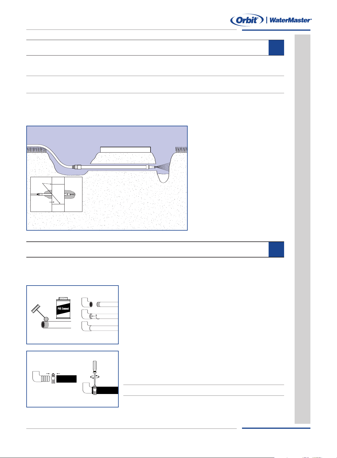
DIG TRENCHES
Using the painted lines as your guide (see System Layout, Page 13) dig trenches to the depth
equired by local codes.
r
Important: Refer to your local codes to determine how deep your header and lateral lines need to be. Always contact your local
utility companies before digging.
5
Methods for Digging Trenches
• By Hand – Ideal for soft soils and very small jobs
• With Trenching Machine – Available at equipment rental dealers
Under Driveways and
Sidewalks
Use an Orbit®Walkway Tunnel Kit
(part # 53333, 91129) to tunnel
under obstacles.
Dig a trench on both sides.
•
• Attach a garden hose to the
tunneling pipe.
• Turn on the garden hose
faucet.
• Work the pipe back and forth,
allowing the water spray to
form a tunnel.
WORKING WITH PIPE
Decide whether you'll use PVC or Polyethylene pipe for your system. Both types are easy to
use, but they are assembled dif
Sprinkler System Layout & Installation Guide
ferently. Read about each type below to make your selection.
Working with PVC Pipe
Using an Orbit
•
the end.
Apply PV
•
provided.
• Insert pipe into fitting.
orking with Polyethylene Pipe
W
• Using an Orbit®cutting tool, cut poly-pipe to length.
• Slide a stainless steel clamp over the end of the pipe.
• Insert a barbed fitting into the pipe.
• Tighten the clamp over the pipe and fitting.
arning: Poly pipe should not be used for the main line to the manifold.
W
®
ting tool, cut pipe to length and clean
cut
C primer and PV
C cement, using instructions
6
15
Page 20
Installation
To
Rea
r M
anif
old
Spri
nkl
er M
ain Line
Main S
prinkl
er
Shu
t O
ff
Water Meter
Front Manifold
1" Male Threaded Fitting
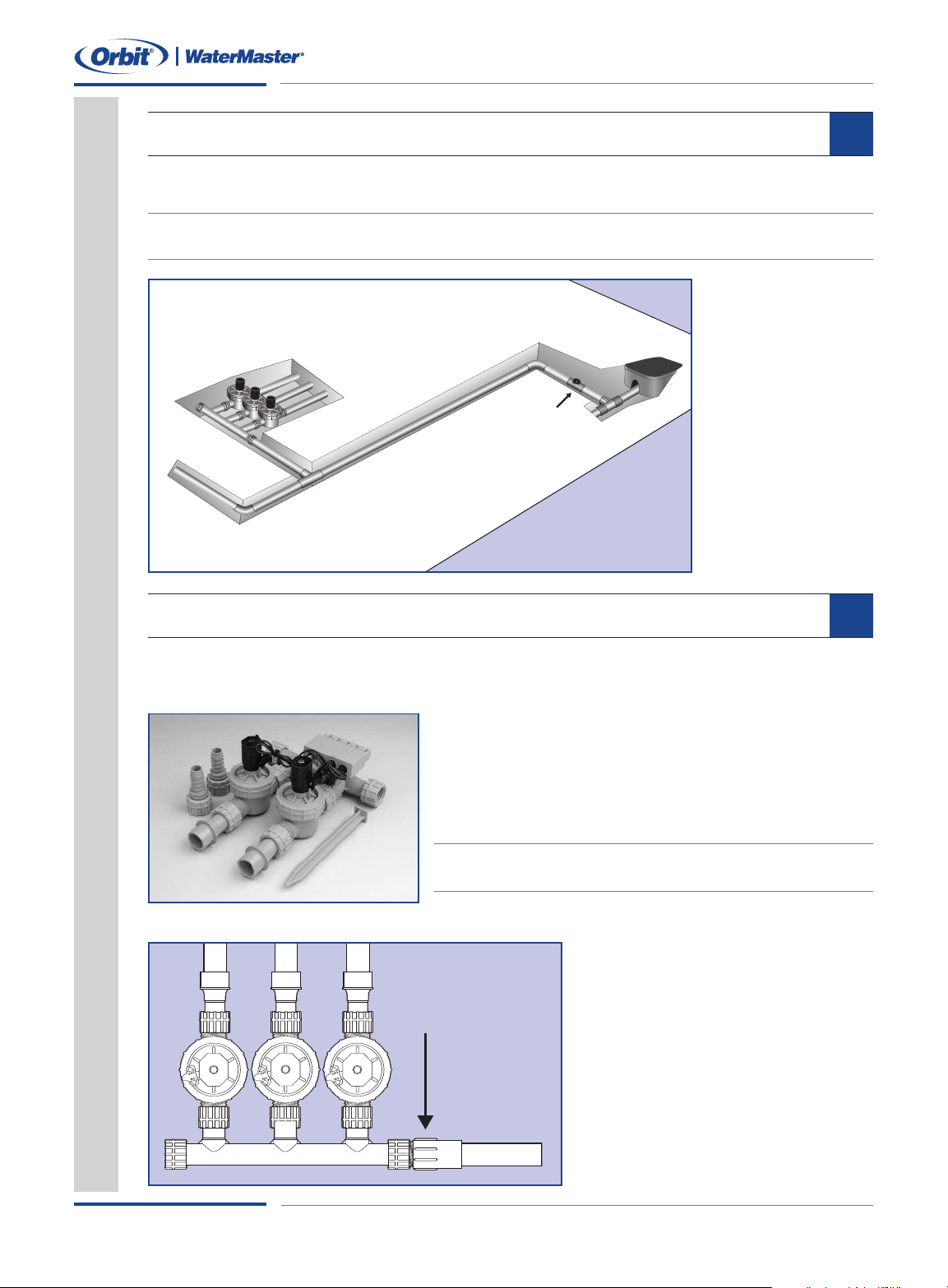
INSTALL MAIN LINE
7
Use PVC schedule 40 (or other pressure-rated pipe) to connect the main shut-off valve to
he valve manifold(s).
t
Important: Use pipe one size larger than your supply line. Using pipe smaller than the main supply line will reduce your water flow
and will lead to gaps in spray coverage. (For example, use 1" pipe if your supply line is 3/4")
Installing main line
pressure-rated pipe
to front and back
manifold
INSTALL MANIFOLD
The easiest way to install a manifold is with an Orbit®Pre-Assembled Manifold. Purchase a
manifold with one valve for each sprinkler zone.
• Installs in minutes
• Works with both Poly-Pipe and PVC Systems
• Cost effective
Expandable for future sprinkler additions
•
Note: Anti-siphon pre-assembled manifolds are available for areas requiring
use of an anti-siphon valve
Pre-Assembled Manifold
Connecting the Manifold to
the Main Line
• Before connecting the manifold,
open the main shut-off valve
t from the main
ting.
to flush dir
sprinkler line.
Connect the Pre-Assembled
•
Manifold to the main sprinkler
line using a 1" threaded fit
8
16
Sprinkler System Layout & Installation Guide
Page 21
Installation
1" Male Threaded Fi
PVC or Poly Cross
Header Line
PVC or Poly Tee
Lateral Line
Fittings with
Threaded Outlet
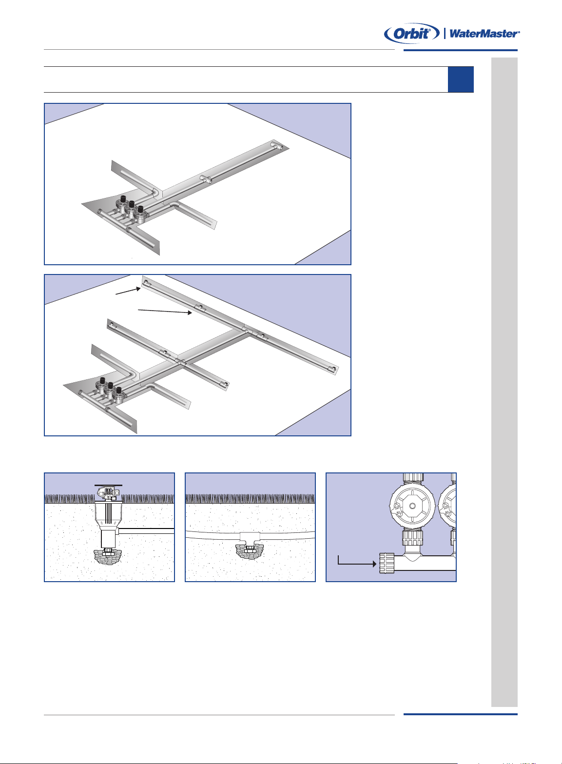
CONNECT ZONES
9
Install Header Lines
Connect 1" pipe to
•
ach valve and run it
e
o the assigned zone.
t
• Use fittings (elbow,
cross or tee) for each
lateral line.
Install Lateral Lines
Connect 3/4"
•
lateral lines to
the header line.
• Run lateral line
to each sprinkler
location.
• Install Tees or Elbow
at each sprinkler
location.
Freezing Areas – Install Line Drains
Replace with
Manual Drain
alve
V
Lateral and Header Lines
er Heads
Canist
End of Spr
sloped line.
Low Spots: Install a tee and automatic drain valve for low spots on sprinkler head lines.
: Install an automatic drain valve in the bot
inkler Line
: Install an automatic drain valve af
tom inlet of all canister
ter the last head on the end of eac
s.
Main Line
Manifold: Remove the end cap and install a ball or gate manual drain valve.
Sprinkler System Layout & Installation Guide
h
17
Page 22
Installation
S
wing Joint
Multi-Flex™
Adjustable Height
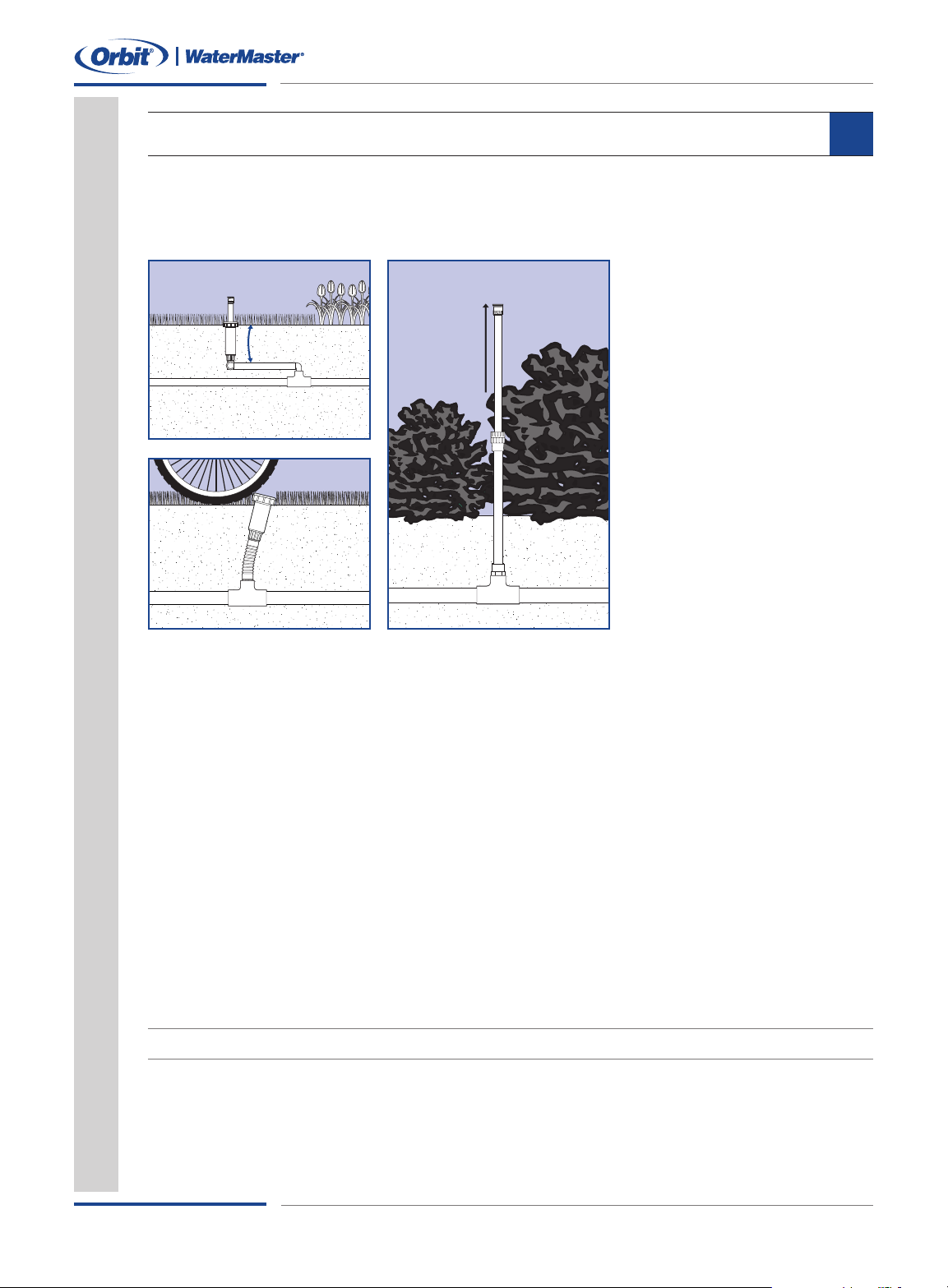
INSTALL RISERS & HEADS
10
Install Risers (Without Heads)
Risers are designed to bring the sprinkler head up to ground height. A wide selection of risers
are available. Select the riser that best fits your needs.
Swing Joints &
Riser Flex
• Easy to adjust sprinkler height
• Resists impact and cracking
• Useful for placing heads in
hard to reach areas
Multi-Flex™Risers
• Comes in various lengths
•
Deflects impact
Aluminum Riser with
Adjustable Nozzle
• Adjusts in Height as Plant
Grows – 16" to 30"
• Easy Pattern Adjustment – 25°
to 360°
Flush Sprinkler Lines – Prior to Installing Heads
• Ensure PVC glue has dried adequately.
• Turn on the main line sprinkler valve.
• Manually turn on one valve at a time (see valve instruction booklet).
•
un eac
R
h valve for a few minutes.
Installing Heads and Testing
• Attach sprinkler heads to each riser and adjust the height to proper level.
• Place enough soil in the trench to stabilize heads but don't fill the trench.
• Manually turn on one valve at a time.
• Check for leaks.
Important: Adjust heads for proper spray pattern and check for adequate head to head coverage.
18
Sprinkler System Layout & Installation Guide
Page 23
Installation
Common Wire From Valves
Common Wire
Wire from Valve 1
Valve 1 Valve 2
W
ire from Valve 2
123456789
P
ump Com1 Com2 24VAC
C
ommon Wire
Common Wire
Sprinkler Wire
Wire 1
W
ire 2
White
CONNECTING SPRINKLER WIRE
11
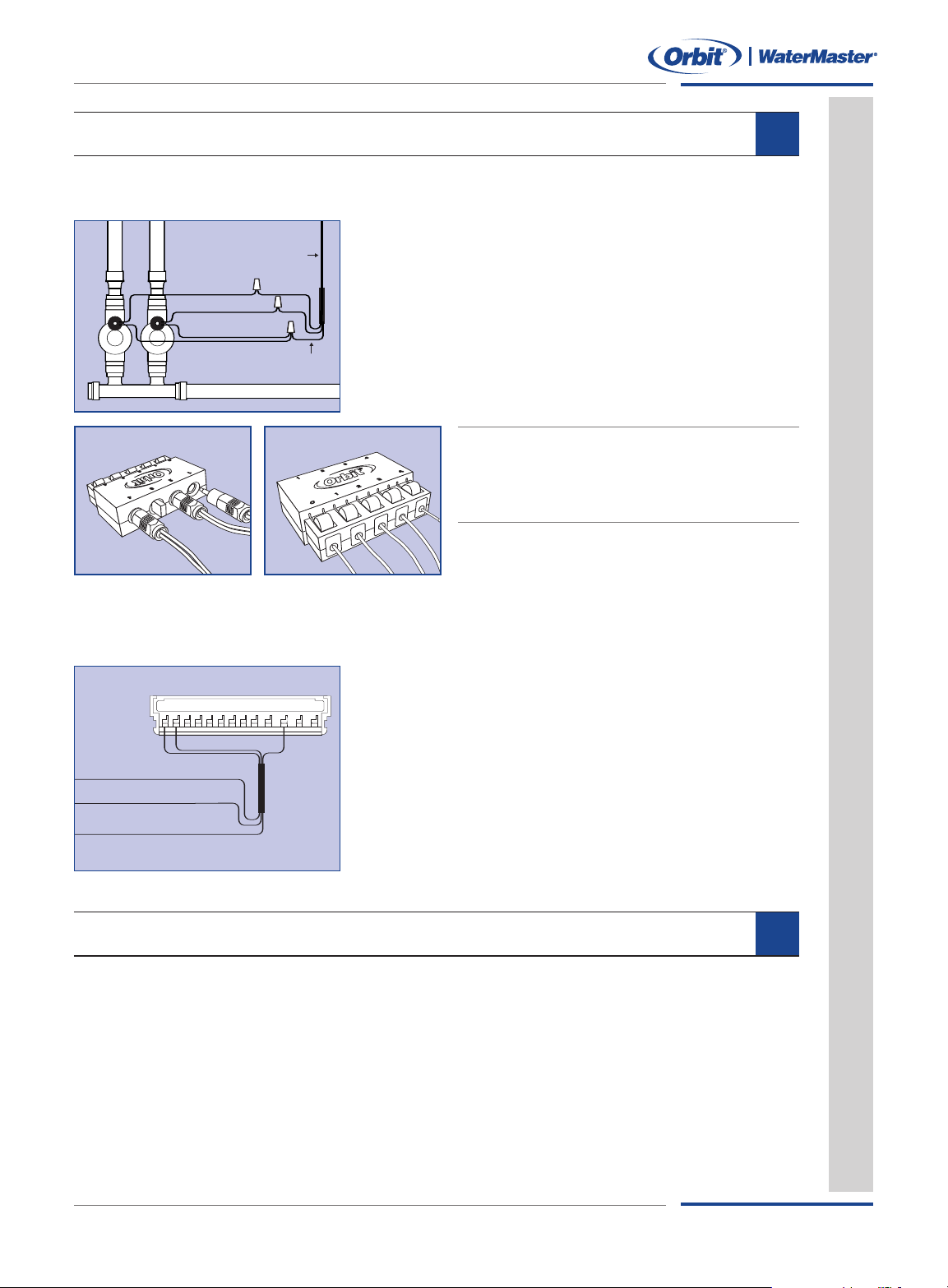
Sprinkler wire consists of one white (common) and 4 or 6 colored strands.The sprinkler wire
eeds to have at least one more wire strand than the number of valves being installed.
n
Wiring the Valves
Using wire nuts and grease caps, connect the wires
as shown:
• Connect one wire from each valve to the white
(common) sprinkler wire.
• Connect the 2nd wire from each valve to
a separate color wire.
Tip: Orbit’s®Pre-Assembled Manifold with Snap-Wire
Connection makes wiring valves easy. Just plug in the valve
jack into the water-tight Snap-Wire
sprinkler wire into the other side. No confusing wiring or
messy grease caps (see page 22 for more info).
™
housing and insert
™
Run Sprinkler Wires to Timer
Most often you can use an existing sprinkler pipe trench to run your sprinkler wire. In areas
of frequent digging, a conduit pipe is used to protect the wire.
Wiring
Your Sprinkler
Timer
• Unplug your timer from the power source (if hard wired
turn off appropriate breaker switch or remove fuse).
• Connect each colored sprinkler wire to a separate
numbered terminal (on the timer).
• Connect the white (common) wire to the common
terminal on the timer.
• Restore power to your timer.
• To test proper wiring, manually run each station
from the timer
.
BURYING SPRINKLER PIPE AND VALVES
ore Burying Trenches:
Bef
1. Check all fittings, heads and valves for leaks.
2.Adjust sprinkler height to proper level.
3.Adjust each head for proper spray pattern and spray distance. (Use your drawings
as a reference.)
Cover manifolds with an Orbit
4.
Sprinkler System Layout & Installation Guide
®
valve bo
x.
12
19
Page 24
Appendix
WATER PRESSURE (PSI)
3/4”
SCH. 40 PVC
1”
Gear Drive
I
mpact Sprinklers
Pop-Up & Shrub Spray Head
Shrub Bubbler
3
0 PSI 40 PSI 50 PSI 60 PSI 70 PSI 80 PSI
Q
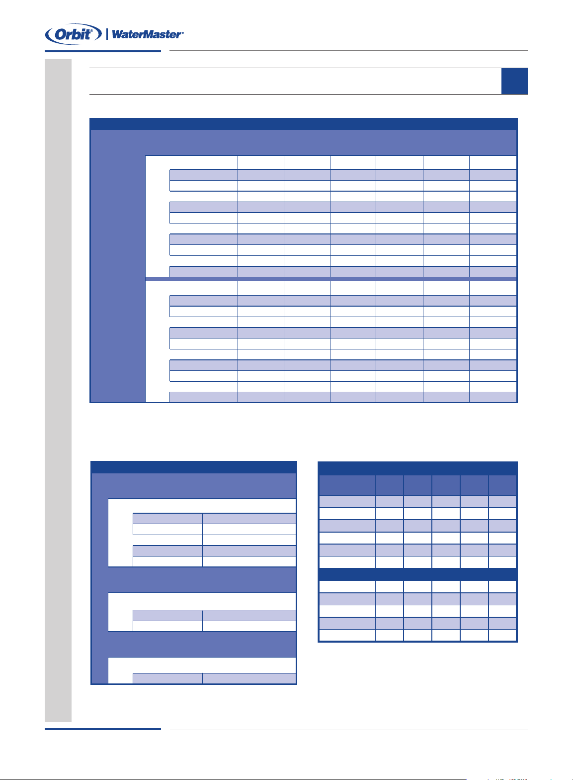
UICK REFERENCE – MAXIMUM HEADS PER ZONE ESTIMATES
M
AIN LINE SIZE
1
223 44
V
oyager II
®
*
2234 55Saturn III
®
*
1
223 44
S
atellite
®
*
1122 341/2” Brass
4
567 89
A
djustable & Fixed**
4 6 8 10 13 15
Mushroom Bubbler***
3446 78Strip Pattern
G
ear Drive
I
mpact Sprinklers
Pop-Up & Shrub Spray Head
Shrub Bubbler
* With pre-installed nozzle
** Based on an average flow rate of 1.6 GPM per head
*** Adjustment set below 1/2 flow
Important: These figures are based on a typical sprinkler system.
Before burying sprinkler pipe, run each zone to confirm adequate
spray coverage.
30 PSI 40 PSI 50 PSI 60 PSI 70 PSI 80 PSI
2
234 56
V
oyager II
®
*
3345 67Saturn III
®
*
2234 56
Satellite
®
*
1123 451/2” Brass
4
5 7 9 10 12
Adjustable & Fixed**
6 8 10 14 16 18
Mushroom Bubbler***
3
457 810Strip Pattern
LARGE AREA SPRINKLERS
Gear Drives
Impact Sprinklers
Pop-Ups
Bubbler
SPRINKLER HEAD TO HEAD SPACING GUIDE
20’ – 40’
Voyager II
®
*
15’ – 30’Saturn III
®
*
20’ – 40’
Satellite
®
*
25’ – 45’1/2” Brass Impact *
10’ – 15’
Adjustable Nozzle
Spot
Bubbler
10’ – 15’Fixed Nozzle
* Spray distance adjusted by diffuser pin
Important: Before burying sprinklers, check for head to head
spray coverage. Adjust if necessary.
MEDIUM AREA SPRINKLERS
SHRUB AND FLOWER
* Factory installed 7” nozzle
Spacing 20’ - 45’
VOYAGER II®POP-UP GEAR DRIVE HEAD
NOZZLES
30 40 50 60 70
PSI PSI PSI PSI PSI
1
2
3
4
5
6
7*
8
9
10
11
12
.5
.7
.9
1.2
1.6
2.0
2.6
3.2
4.2
–
–
–
.6
.8
1.0
1.4
1.8
2.4
3.0
3.7
4.9
6.0
8.0
11.4
.7
.9
1.2
1.6
2.0
2.7
3.4
4.2
5.5
6.8
8.9
12.2
.8
1.0
1.3
1.8
2.2
2.9
3.7
4.6
6.0
7.6
9.8
13.2
–
–
–
–
–
–
–
–
–
8.2
10.5
14.4
APPENDIX
C
hart 1
A
Chart 2 Chart 3
20
Sprinkler System Layout & Installation Guide
Page 25
Appendix
SELECTING THE BEST COMPONENTS FOR YOUR SPRINKLER SYSTEM
A
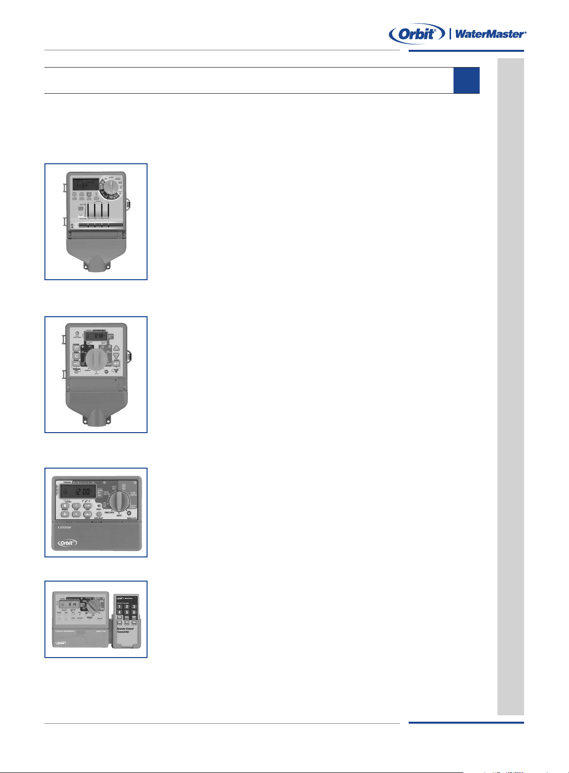
Sprinkler Timers
The timer is the brains for your underground sprinkler system that controls when and how long
to irrigate your yard. Orbit's®line of timers are known for reliability, ease of installation, programming simplicity and a 6 year warranty, making Orbit®Timers the #1 choice by homeowners.
Slide Switch
The easiest timer to program, with water saving features.
• Large Display with Text Messaging – Easy to program, easy to use
• 3 Independent Programs – Days of Week, Watering Intervals and
Odd/Even Days
Water Saving Features – Water Budgeting, Rain Delay & Rain
•
Sensor ports
• Slide Switch Feature – One-Touch sliding bar adjusts each station
watering duration. Ideal for lawn and micro-irrigation.
• Pump or Mast
Available in 4, 6, 9 & 12 Stations
Outdoor version available
Super Dial
• Large Dial and Buttons – Simplify programming
• 2 Independent Program – Days of Week, Watering Intervals
and Odd/Even Days
• Rain Delay – Settings for 24, 48 and 72 hours
• Screw-Less Terminals – No tools required
• Pump or MasterValve Feature
• Up to 8 Start Times Per Day – Ideal for new lawn and
reducing run-off
er Valve Feature
Available in 4, 6, 9 & 12 Stations
ailable
Outdoor version a
v
Dual Program
• Easy t
•2independent programs – Days of the week and Watering intervals
• Water-Saving Rain Delay Feature – Settings for 24, 48, and 72 hours
• Up to 8 Start Times Per Day – Ideal for new lawn and reducing run-off
o Pr
Available in 4 and 6 Stations
Dual Pr
Same features as the Dual Program timer with the addition
of Wireless Remote
• Time Saver – Ideal for installation, testing, maintenance, and
•
ogr
sprinkler adjustments
Allows Operation of Individual Stations – Up to 200 feet
6 Stations only
ogram
am
With
eless Remote
Wir
Sprinkler System Layout & Installation Guide
21
Page 26
Pre-Assembled Valve Manifolds
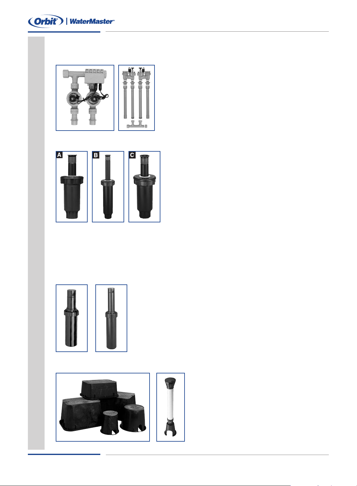
Orbit®valves continue to set a high standard for solid construction and reliability.
Appendix
Pre-Assembled Manifolds with Snap-Wire
• The most complete and reliable multi-valve system
• Installs in minutes
• Snap-Wire™plug-in system simplifies wiring
• Works with PVC or Poly-Pipe
6Year Warranty
•
Available:
• Standard Inline – 2 and 3 valves
• Anti-Siphon – 2 valves
Spring-Loaded Pop-Ups with Adjustable Nozzle
A Standard Top –The standard plastic cap with an
adjustable nozzle offers convenience, ease and value for
the homeowner. “Just set and Forget.”
b Soft Top™–The Soft Top adds a soft cushioned
rubberized cap.
C Hard Top™–The Hard Top adds a metal cap for high
traffic areas, such as driveways and sidewalks, where
sprinklers are subject to contact with vehicles and yard
equipment.
es
ur
Feat
• Easy to Adjust Spray Pattern – 25˚ to 360˚
• Spacing – 10' to 15'
• Available in 2" and 4" Pop-Up Height
• 5 Year Warranty
™
22
Voyager II®& Saturn III®Gear Drives
The #1 Choice by Homeowners
• Simple Pattern Adjustment – 40˚ to 360˚
4" Pop-Up Height – Clears long grass
•
• Easy to Adjust Spray Distance – 20' to 40' Voyager II®, 15' to 30'
aturn III
S
• Quiet and Smooth Rotating Spray
• 5 Year Warranty – Dependable and trouble-free performance
• Additional Nozzle Sizes Available – 20 for Voyager II®and 3 for
Saturn III
®
®
Voyager II®: Model # 55060, 55061; Saturn III®: Model 55059, 55069
Orbit®Valve Box
able long lasting constr
Dur
vailable:
A
• 20" Jumbo Rectangle Box
• 12" Standard Rectangle Box
ound Box
0" R
1
•
• 6" Round Box
• 32" to 54" Adjustable Curb Box
Sprinkler System Layout & Installation Guide
uction
Page 27
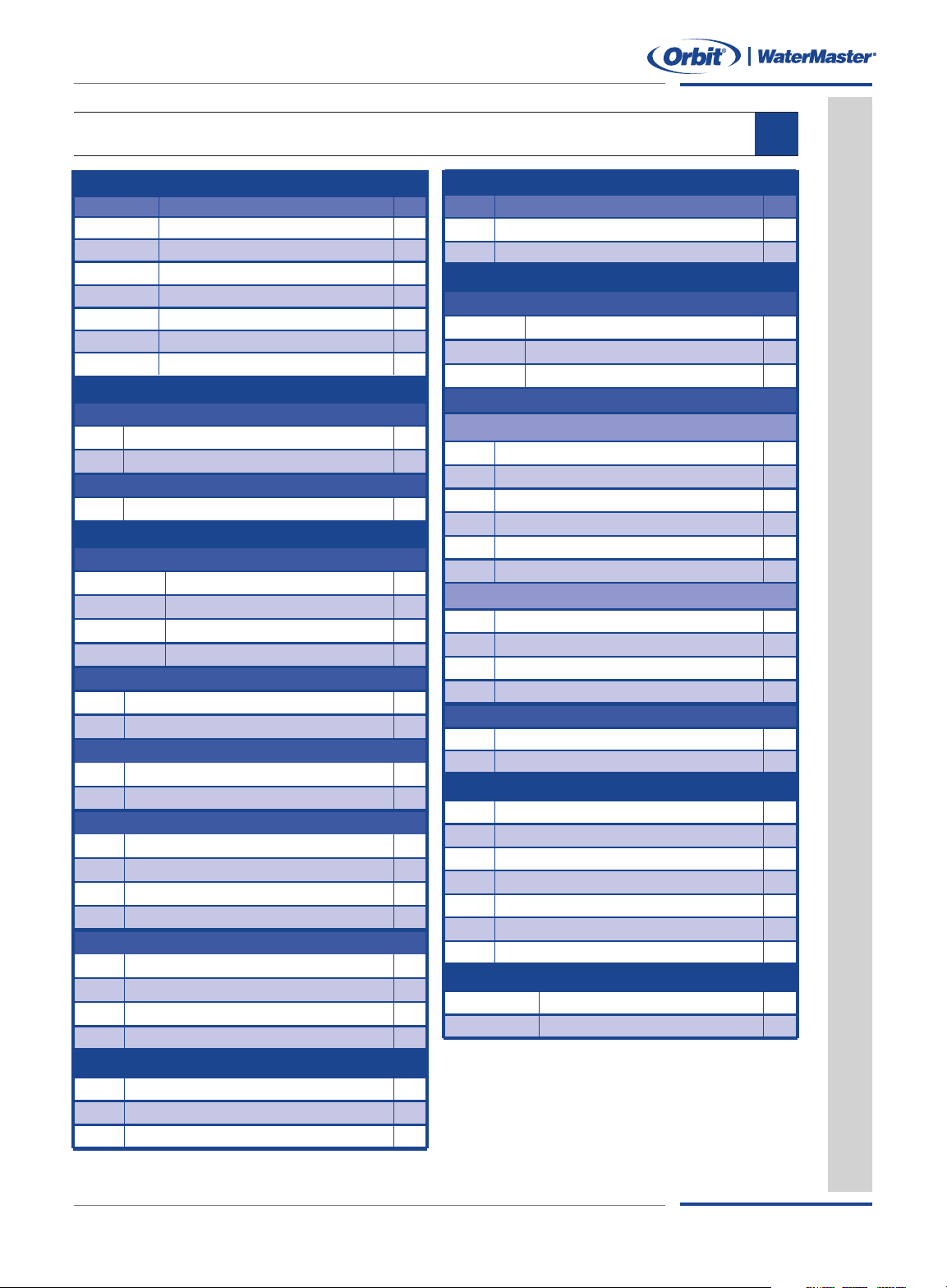
Part # Description Qty
7 Conductor 100’ – For up to 6 Valves
5 Conductor 100’ – For up to 4 Valves
57088
57093
54042 Mushroom Bubbler
37330
Aluminum Riser 16" to 30" with Adjustable Nozzle
37264
1/2” x 1/2” x 12” Pre-Assembled Swing Joint
37265
3/4” x 1/2” x 12” Pre-Assembled Swing Joint
37163 1/2" Male x Female Swing Joint Elbow
37164 3/4" Male x Female Swing Joint Elbow
37159 1/2" Male x Barb Elbow – Riser Flex
37162 3/4" Male x 1/2" Barb Elbow – Riser Flex
37154 1/2" x 50' Riser Flex Pipe
37112 1/2" x 6" Multi-Flex
®
37069/38500 1/2" x 6" Cut-Off
57150
57153
2 Valve with Snap-Wire™Connection
3 Valve with Snap-Wire
™
Connection
57172 2 Valve Anti-Siphon
57623
57624
3/4” Anti-siphon Threaded
1” Anti-siphon Threaded
6 Station Slide Switch
12 Station Slide Switch
6 Station Super Dial
9 Station Super Dial
6 Station w/ Wireless Remote
4 Station Dual Program
Pump Start Relay
57467 1” Male Threaded Jar Top
57461/57661 1” Female Threaded Jar Top
57100 3/4” Threaded
57101 1” Threaded
51040 1/2” Plastic Automatic Drain Valve
53266 28” Curb Key
53034 5’ Steel Curb Key
51050 3/4” Double Check Valve
51057 3/4” Pressure Vacuum Breaker
53210 6" Circular
53211 10" Circular
53212 12" Standard Rectangle
53029 32" to 54" Adjustable Curb Box
53020 Orbit
®
pressure gauge
26085 Pipe cutting tool
53326 Sprinkler flags
53333 Walkway tunnel kit
* Outdoor models
5
5060/55061 Voyager II
®
G
ear Drive
55059/55069 Saturn III
®
Gear Drive
55012 Satellite
®
Pop-Up Impact
54115 2" Hard Top
™
54118 4" Hard Top
™
54113 2" Soft Top
™
54114 4" Soft Top
™
54116 2" Standard
54117 4" Standard
54016 2” Full Pattern
54017 2” Half Pattern
54018 2” Quarter Pattern
54127 2” Center Strip
QtyPart # Description
Accessories
A
utomatic Timers & Pump Start Relay
Backflow Valve
Valve Boxes
Pre-Assembled Manifolds
Inline
Anti-siphon
Tools
Automatic Valves
Inline
Anti-siphon
Sprinkler Wire
Medium Area – Spring Loaded Pop-Ups
Spring-Loaded Pop-Up w/ Adjustable Pattern
Spring-Loaded Pop-Up w/ Fixed Pattern
Small Area
Sprinklers
Large Area
Riser Flex and Swing-Joints
Multi-Flex
®
Riser & Cut-Off Riser
Parts List
PARTS LIST
Sprinkler System Layout & Installation Guide
A
23
Page 28
PN 53251 Rev E
Irrigation Products, Inc.
845 North Overland Road
North Salt Lake, Utah 84054 USA
www.orbitonline.com
Toll-Free 1-800-488-6156
Phone 801-299-5555
Fax 801-299-5547
 Loading...