

Page 1

Operating Manual
Optimod-PC
1101
Digital Audio Processor PCI Sound Card
Software Version 1.0
Page 2

IMPORTANT NOTE: Refer to the unit’s rear panel for your Model #.
Model Number: Description:
1101 OPTIMOD-PC Digital Audio Processor on a PCI Sound Card.
OPTIMOD-PC is a broadcast-quality audio processor offering gain-riding AGC, parametric equalization, multiband compressor, and look-ahead peak limiting.
1101/CBLXLR Pre-wired cable option for 1101 I/O Interface, terminated in XLR connectors.
1101/CBLRCA Pre-wired cable option for 1101 I/O Interface, terminated in RCA connectors.
1101/CBL Pre-wired cable option for 1101 I/O Interface, unterminated.
CAUTION:
NO USER SERVICEABLE PARTS INSIDE. REFER SERVICING TO QUALIFIED SERVICE PERSONNEL.
TO REDUCE THE RISK OF ELECTRICAL SHOCK, DO NOT REMOVE COVER (OR BACK).
WARNING: TO REDUCE THE RISK OF FIRE OR ELECTRICAL SHOCK,
DO NOT EXPOSE THIS APPLIANCE TO RAIN OR MOISTURE.
This symbol, wherever it appears, alerts you to
the presence of uninsulated dangerous voltage
inside the enclosure ⎯ voltage that may be
sufficient to constitute a risk of shock.
This symbol, wherever it appears, alerts you to important
operating and maintenance instructions in the accompa-
nying literature. Read the manual.
In accordance to the WEEE (waste electrical and electronic equipment) directive of the European Parliament, this product must not be discarded into the
municipal waste stream in any of the Member States. This product may be
sent back to your Orban dealer at end of life where it will be reused or recycled
at no cost to you.
If this product is discarded into an approved municipal WEEE collection site or
turned over to an approved WEEE recycler at end of life, your Orban dealer
must be notified and supplied with model, serial number and the name and
location of site/facility.
Please contact your Orban dealer for further assistance.
www.orban.com
Page 3

PLEASE READ BEFORE PROCEEDING!
Manual
Please review the Manual, especially the installation section, before installing the unit in your computer.
Trial Period Precautions
If your unit has been provided on a trial basis:
You should observe the following precautions to avoid reconditioning charges in case you later wish to return the unit to
your dealer.
(1) Note the packing technique and save all packing materials. It is not wise to ship in other than the factory carton. (Re-
placements cost $35.00).
(2) Avoid scratching the plating. Set the unit on soft, clean surfaces.
(4) Use care and proper tools in removing and tightening screws to avoid burring the heads.
Packing
When you pack the unit for shipping:
(1) Wrap the unit in its original plastic bag to avoid marring the unit.
(2) Seal the carton with tape.
If you are returning the unit permanently (for credit), be sure to enclose:
The Manual(s)
The Registration/Warranty Card
Your dealer may charge you for any missing items.
If you are returning a unit for repair, do not enclose any of the above items.
Further advice on proper packing and shipping is included in the Manual (see Table of Contents).
Trouble
If you have problems with installation or operation:
(1) Check everything you have done so far against the instructions in the Manual. The information contained therein is
based on our years of experience with OPTIMOD and broadcast stations.
(2) Check the other sections of the Manual (consult the Table of Contents) and search the text to see if there might be
some suggestions regarding your problem.
(3) After reading the section on Factory Assistance, you may call Orban Customer Service for advice during normal Ari-
zona business hours. The number is +1 480.403.8300.
Page 4

Page 5

Operating Manual
Optimod-PC
1101
Digital Audio Processor PCI Sound Card
Software Version 1.0
Page 6

This equipment generates, uses, and can radiate radio-frequency energy. If it is not
installed and used as directed by this manual, it may cause interference to radio
communication. This equipment complies with the limits for a Class A computing
device, as specified by FCC Rules, Part 15, subject J, which are designed to provide reasonable protection against such interference when this type of equipment
is operated in a commercial environment. Operation of this equipment in a residential area is likely to cause interference. If it does, the user will be required to eliminate the interference at the user’s expense.
This digital apparatus does not exceed the Class A limits for radio noise emissions
from digital apparatus set out in the radio Interference Regulations of the Canadian
Department of Communications. (Le present appareil numerique n’emet pas de
bruits radioelectriques depassant les limites applicables aux appareils numeriques
(de las class A) prescrites dans le Reglement sur le brouillage radioelectrique
edicte par le ministere des Communications du Canada.)
WARNING
WARNING
Perform the installation under static control conditions. Simply walking across a rug
can generate a static charge of 20,000 volts. This is the spark or shock you may
have felt when touching a doorknob or some other conductive item. A much
smaller static discharge is likely to destroy one or more of the CMOS semiconductors employed in OPTIMOD-FM. Static damage will not be covered under warranty.
There are many common sources of static. Most involve some type of friction between two dissimilar materials. Some examples are combing your hair, sliding
across a seat cover or rolling a cart across the floor. Since the threshold of human
perception for a static discharge is 3000 V, you may not notice damaging discharges.
Basic damage prevention consists of minimizing static generation, discharging any
accumulated static charge on your body or workstation, and preventing that discharge from being sent to or through an electronic component. You should use a
static grounding strap (grounded through a protective resistor) and a static-safe
workbench with a conductive surface. This will prevent any buildup of damaging
static.
Orban is a registered trademark.
All trademarks are property of their respective companies.
This manual was published November 2008.
© Copyright Orban
CAUTION
Phone: +1 480 403-8300; Fax: +1 480 403-8301; E-Mail: [email protected]; Website: www.orban.com
7970 South Kyrene, Tempe, AZ 85284 USA
Page 7

Table of Contents
PLEASE READ BEFORE PROCEEDING!-------------------------------------------------------- 0-3
Table of Contents --------------------------------------------------------------------------------- 0-7
Index--------------------------------------------------------------------------------------------------0-12
----------------------------------------------------------------
SECTION 1 INTRODUCTION
------------------------------------------------------------------------------------------------------- 1-1
ABOUT THIS MANUAL------------------------------------------------------------------------------------ 1-1
AUDIO PROCESSING FOR LEVEL CONTROL-------------------------------------------------------------- 1-1
Audio Processing: Making Broadcasts/Netcasts Sound Professional ------------------------- 1-1
Figure 1-1: Unprocessed Audio-------------------------------------------------------------------------- 1-2
Figure 1-2: Same Audio Processed Through OPTIMOD-PC-------------------------------------- 1-2
Audio Processing for Netcasts --------------------------------------------------------------------------- 1-3
Measuring Studio and Transmission Levels---------------------------------------------------------- 1-3
Figure 1-3: Absolute Peak Level, VU and PPM Reading ----------------------------------------- 1-3
Controlling Program Levels in a Playout System before OPTIMOD-PC --------------------- 1-4
THE OPTIMOD-PC DIGITAL AUDIO PROCESSOR----------------------------------------------------- 1-5
General Features----------------------------------------------------------------------------------- 1-6
Adaptability through Multiple Audio Processing Structures------------------------- 1-9
PRESETS IN OPTIMOD-PC-----------------------------------------------------------------------------1-10
Factory Processing Presets ---------------------------------------------------------------------1-10
User Processing Presets -------------------------------------------------------------------------1-11
INPUT/OUTPUT CONFIGURATION-----------------------------------------------------------------------1-12
Figure 1-4: OPTIMOD-PC Signal Flow and I/O----------------------------------------------------- 1-13
Digital AES3 Left/Right Input/Output ------------------------------------------------------1-13
Analog Left/Right Input/Output -------------------------------------------------------------1-14
The Orban I/O Mixer-----------------------------------------------------------------------------1-14
OVERVIEW OF AN OPTIMOD-PC INSTALLATION----------------------------------------------------1-16
Figure 1-5: Typical I/O mixer---------------------------------------------------------------------------- 1-16
Simple Operation in One Host Computer-------------------------------------------------1-18
Security ----------------------------------------------------------------------------------------------1-18
Networking OPTIMOD-PC Cards -------------------------------------------------------------1-20
LOCATION OF OPTIMOD-PC FOR NETCASTING -----------------------------------------------------1-21
Genlocking OPTIMOD-PC Cards to a Reference Sample Frequency---------------1-22
STUDIO-TRANSMITTER LINK IN DIGITAL BROADCASTING --------------------------------------------1-22
Transmission from Studio to Transmitter -------------------------------------------------1-23
Digital links -------------------------------------------------------------------------------------------------- 1-23
Microwave STLs--------------------------------------------------------------------------------------------- 1-25
Analog Telephone/Landline (PTT/Post Office Line) --------------------------------------------- 1-26
LOCATION OF OPTIMOD-PC IN DIGITAL RADIO SERVICE ------------------------------------------1-26
At the Transmitter is Best ------------------------------------------------------------------------------- 1-26
Where Access to the Transmitter is not Possible------------------------------------------------- 1-26
OPTIMOD-PC at the Transmitter: Gain Control before the STL ----------------------------- 1-27
USING LOSSY DATA REDUCTION IN THE AUDIO CHAIN BEFORE OPTIMOD-PC------------------1-28
INTERFACING TO THE TRANSMITTER--------------------------------------------------------------------1-28
Sync Input ---------------------------------------------------------------------------------------------------- 1-28
Sample Rate and Audio Bandwidth ----------------------------------------------------------------- 1-28
Subframe Delay -------------------------------------------------------------------------------------------- 1-29
SETTING OUTPUT/MODULATION LEVELS --------------------------------------------------------------1-29
MONITORING ON LOUDSPEAKERS AND HEADPHONES -----------------------------------------------1-30
STREAMING AND NETCASTING APPLICATIONS --------------------------------------------------------1-31
Page 8

Using OPTIMOD-PC in Streaming Applications--------------------------------------------------- 1-31
Using OPTIMOD-PC to Prepare Audio Files for Download ----------------------------------- 1-31
Loudness------------------------------------------------------------------------------------------------------ 1-32
Choosing your Encoder ---------------------------------------------------------------------------------- 1-32
SHIPPING INSTRUCTIONS -------------------------------------------------------------------------------- 1-32
WARRANTY, USER FEEDBACK ------------------------------------------------------------------------- 1-33
User Feedback------------------------------------------------------------------------------------- 1-33
LIMITED WARRANTY---------------------------------------------------------------------------- 1-33
INTERNATIONAL WARRANTY ---------------------------------------------------------------- 1-34
EXTENDED WARRANTY ------------------------------------------------------------------------ 1-34
-----------------------------------------------------------------SECTION 2 INSTALLATION
-------------------------------------------------------------------------------------------------------2-1
INSTALLING OPTIMOD-PC IN WINDOWS
1. Unpack and inspect. ------------------------------------------------------------------------------ 2-1
2. Mount OPTIMOD-PC in a free PCI slot in your computer. ---------------------------- 2-2
3. Install driver and software. --------------------------------------------------------------------- 2-2
Figure 2-1: OPTIMOD-PC Network Scenarios-------------------------------------------------------- 2-3
Figure 2-2: Wiring Diagram for the OPTIMOD-PC XLR Cable Assembly --------------------2-4
Figure 2-3: Wiring Diagram for the OPTIMOD-PC RCA Cable Assembly-------------------- 2-4
4. Plan your installation. ---------------------------------------------------------------------------- 2-4
Figure 2-4: The Orban Control Application---------------------------------------------------------- 2-5
5. Connect hardware inputs and outputs. (optional)-------------------------------------- 2-5
6. Set up passwords and card names for cards in your computer. (optional) ------ 2-6
Figure 2-5: Card & Security Administration---------------------------------------------------------- 2-7
8. Edit the local OPTIMOD-PC server’s network accessibility, port numbers, and
Service Security Password. (optional)---------------------------------------------------------------- 2-10
10. Add remote cards to your list of available cards. (optional) ----------------------- 2-10
11. Connect to a remote card. (optional) ----------------------------------------------------- 2-12
12. Change passwords and card names over a network. (optional) ------------------ 2-12
13. Delete a remote computer’s profile. (optional)---------------------------------------- 2-13
15. Simple installations: Connecting to an OPTIMOD-PC card.------------------------- 2-14
16. Connect inputs and outputs. (optional) -------------------------------------------------- 2-14
®
COMPUTERS ----------------------------2-1
AUDIO INPUT AND OUTPUT CONNECTIONS ----------------------------------------- 2-15
Cable ------------------------------------------------------------------------------------------------- 2-15
Connectors ----------------------------------------------------------------------------------------- 2-15
Analog Audio Input ----------------------------------------------------------------------------- 2-15
Analog Audio Monitor Output -------------------------------------------------------------- 2-16
AES3 DIGITAL INPUT AND OUTPUT----------------------------------------------------- 2-16
GROUNDING -----------------------------------------------------------------------------------2-17
Power Ground ------------------------------------------------------------------------------------ 2-18
SETUP: THE OPTIMOD-PC CONTROL APPLICATION------------------------------------------------ 2-18
1. From the Tools menu, bring up the I/O Mixer. ----------------------------------------- 2-18
2. Select the card you are setting up.--------------------------------------------------------- 2-19
3. Configure global audio processing parameters. --------------------------------------- 2-20
Figure 2-6: Configuration Page in the I/O Mixer------------------------------------------------- 2-21
4. Set digital output properties. (optional) ------------------------------------------------- 2-22
Page 9

Figure 2-7: Processor Mixer Page in I/O Mixer --------------------------------------------------- 2-24
INPUT SETUP----------------------------------------------------------------------------------- 2-24
About the Interaction between the OPTIMOD-PC Input Mixers and the Microsoft
Windows Mixer -----------------------------------------------------------------------------------2-25
Figure 2-8: MS Mixer Output--------------------------------------------------------------------------- 2-25
Figure 2-9: MS Mixer Input ----------------------------------------------------------------------------- 2-26
Input Setup Procedure --------------------------------------------------------------------------2-26
1. Adjust the Analog Input Reference Level control. ------------------------------------ 2-26
2. Adjust the Analog Output Reference Level control. --------------------------------- 2-27
3. Select the Stereo/Mono input mode for the analog input. ------------------------ 2-28
4. Adjust the Processor mixer analog input fader. --------------------------------------- 2-28
5. Adjust the Analog L/R Input Balance Control. (optional) --------------------------- 2-30
6. Adjust the remaining input faders. (optional) ----------------------------------------- 2-30
7. Set up the automatic backup feed function. (optional)----------------------------- 2-30
Figure 2-10: Output Levels Page in I/O Mixer ----------------------------------------------------- 2-31
OUTPUT AND ROUTING SWITCHER SETUP -------------------------------------------------------------2-31
THE DIRECT MIXER --------------------------------------------------------------------------------------2-32
INTERFACING OPTIMOD-PC WITH WAVE DEVICES------------------------------------------------2-33
Turning Off Windows Sounds ----------------------------------------------------------------2-33
Applying Output from WAVE Applications to OPTIMOD-PC -----------------------2-33
Applying OPTIMOD-PC’s Output to WAVE Devices ------------------------------------2-34
Enabling the Windows 2003 Server Audio Service ---------------------------------------------- 2-35
PROBLEMS AND POSSIBLE CAUSES ---------------------------------------------------------------------2-36
When I first turn on my computer, the sound seems wrong.-------------------------------- 2-36
When I Launch the OPTIMOD-PC control application, the meters do not move and I
cannot control my card. --------------------------------------------------------------------------------- 2-36
I can’t connect to a given OPTIMOD-PC card from my network. --------------------------- 2-36
I get clicks when I source my WAVE material from a CD. ------------------------------------- 2-37
I get clicks when I source my WAVE material from my computer’s hard drive.-------- 2-37
I get clicks in the 1101’s WAVE output.------------------------------------------------------------- 2-38
I am running Windows 2003 and I cannot get audio to pass through OPTIMOD-PC’s
WAVE inputs and outputs. ----------------------------------------------------------------------------- 2-38
Meters on Optimod-PC Control Application freeze temporarily but audio continues to
be processed normally. ---------------------------------------------------------------------------------- 2-38
RFI, hum, clicks, or buzzes ------------------------------------------------------------------------------ 2-38
Poor peak level control ---------------------------------------------------------------------------------- 2-38
Audible distortion ----------------------------------------------------------------------------------------- 2-38
Audible noise in processed audio -------------------------------------------------------------------- 2-39
Shrill, harsh sound; excessive sibilance-------------------------------------------------------------- 2-40
Gain pumping when high frequency energy is present --------------------------------------- 2-40
System receiving OPTIMOD-PC’s AES digital output will not lock-------------------------- 2-40
System will not pass line-up tones at full output level/100% modulation -------------- 2-40
General dissatisfaction with subjective sound quality ----------------------------------------- 2-40
TECHNICAL SUPPORT ------------------------------------------------------------------------------------2-41
ADDING A CUSTOM LOGO------------------------------------------------------------------------------2-41
USING WINDOWS FIREWALL WITH OPTIMOD-PC ----------------------------------------------------2-42
NAT (Network Address Translation) Firewalls -------------------------------------------2-44
---------------------------------------------------------------------SECTION 3 OPERATION
------------------------------------------------------------------------------------------------------- 3-1
Page 10

Figure 3-1: The OPTIMOD-PC Control Application ------------------------------------------------ 3-1
THE OPTIMOD-PC CONTROL APPLICATION ----------------------------------------------------------3-1
INTRODUCTION TO PROCESSING -------------------------------------------------------------------------3-4
Some Audio Processing Concepts----------------------------------------------------------------------- 3-4
Distortion in Processing------------------------------------------------------------------------------------ 3-4
Loudness and Distortion----------------------------------------------------------------------------------- 3-4
Speech/Music Detector------------------------------------------------------------------------------------- 3-5
Processing for Low Bitrate Codecs ------------------------------------------------------------3-5
Optimod-PC in Radio-Oriented Applications: From Bach to Rock------------------- 3-6
Sound for Picture Applications: Controlling Dynamic Range-------------------------3-7
Protection Limiting --------------------------------------------------------------------------------3-7
Studio AGC-------------------------------------------------------------------------------------------3-8
ABOUT OPTIMOD-PC’S SIGNAL PROCESSING FEATURES --------------------------------------------3-8
Dual-Mono Architecture -------------------------------------------------------------------------3-8
Audio Processing Signal Flow ------------------------------------------------------------------3-9
Figure 3-2: Simplified OPTIMOD-PC Digital Signal Processing Diagram -------------------- 3-9
Two-Band Purist Processing------------------------------------------------------------------- 3-12
Input/output Delay ------------------------------------------------------------------------------ 3-12
CUSTOMIZING OPTIMOD-PC’S SOUND ------------------------------------------------------------- 3-13
Basic Control--------------------------------------------------------------------------------------- 3-13
Gain Reduction Metering---------------------------------------------------------------------- 3-15
Fundamental Requirements: High-Quality Source Material and Accurate
Monitoring----------------------------------------------------------------------------------------- 3-15
ABOUT THE PROCESSING STRUCTURES ---------------------------------------------------------------- 3-15
FACTORY PROGRAMMING PRESETS-------------------------------------------------------------------- 3-17
Protection and AGC Presets------------------------------------------------------------------- 3-18
Table 3-1: Protection and AGC Presets-------------------------------------------------------------- 3-19
Radio-Style Presets------------------------------------------------------------------------------- 3-20
Table 3-2: Radio-Style Presets-------------------------------------------------------------------------- 3-21
Sound for Picture Presets ---------------------------------------------------------------------- 3-26
Table 3-3: Factory Programming Presets (Video) ------------------------------------------------ 3-26
Table 3-4: Equalization Controls --------------------------------------------------------------------- 3-27
EQUALIZER CONTROLS ---------------------------------------------------------------------------------- 3-27
STEREO ENHANCER CONTROLS------------------------------------------------------------------------- 3-32
Table 3-5: Stereo Enhancer Controls----------------------------------------------------------------- 3-32
Table 3-6: AGC Controls --------------------------------------------------------------------------------- 3-33
AGC CONTROLS----------------------------------------------------------------------------------------- 3-33
DISTORTION CONTROL---------------------------------------------------------------------------------- 3-38
Figure 3-3: Bass Clipper Input/Output Transfer Curves as Bass Clip Shape Control is
Varied from 0.0 (Hard) to 10.0 (Soft) ---------------------------------------------------------------- 3-39
Table 3-7: Distortion Control Adjustments -------------------------------------------------------- 3-40
THE TWO-BAND STRUCTURE--------------------------------------------------------------------------- 3-40
Customizing the Settings ---------------------------------------------------------------------- 3-41
The Two-Band Structure’s Full and Advanced Setup Controls --------------------- 3-41
Table 3-8: Two-Band Controls ------------------------------------------------------------------------- 3-42
THE FIVE-BAND STRUCTURE --------------------------------------------------------------------------- 3-45
Putting the Five-Band Structure on the Air ---------------------------------------------- 3-45
Table 3-9: Five-band Controls-------------------------------------------------------------------------- 3-46
Customizing the Settings ---------------------------------------------------------------------- 3-46
The Five-Band Structure’s Full and Advanced Setup Controls ---------------------- 3-46
Table 3-10: Multiband Attack / Release Controls ------------------------------------------------ 3-47
Table 3-11: MB Band Mix Controls ------------------------------------------------------------------- 3-51
Page 11

IF THE HOST COMPUTER RESTARTS OR CRASHES… --------------------------------------------------3-53
USING OPTIMOD-PC FOR PRODUCTION AND MASTERING ----------------------------------------3-54
CREATING CUSTOM “FACTORY” PRESETS-------------------------------------------------------------3-57
Table 3-12: LESS-MORE Reference--------------------------------------------------------------------- 3-59
-------------------------------------------------------SECTION 4 SOFTWARE SUMMARY
------------------------------------------------------------------------------------------------------- 4-1
OPTIMOD-PC SOFTWARE SUMMARY------------------------------------------------------------------- 4-1
Application Installation File ------------------------------------------------------------------------------ 4-1
Driver Files -----------------------------------------------------------------------------------------------------4-2
Driver ------------------------------------------------------------------------------------------------------------ 4-2
Service----------------------------------------------------------------------------------------------------------- 4-2
Agent (Tray Icon) -------------------------------------------------------------------------------------------- 4-2
Control Application ----------------------------------------------------------------------------------------- 4-3
Registry --------------------------------------------------------------------------------------------------------- 4-3
Hardware I/O and PCI Expansion Chassis ------------------------------------------------------------- 4-3
ABOUT THE OPTIMOD-PC DRIVER AND SERVICE---------------------------------------------------- 4-3
------------------------------------------------------------- SECTION 5 UNINSTALLATION
------------------------------------------------------------------------------------------------------- 5-1
UNINSTALLING THE OPTIMOD-PC SOFTWARE ------------------------------------------------------- 5-1
------------------------------------------------------------------ SECTION 6 CONTROL API
------------------------------------------------------------------------------------------------------- 6-1
OPTIMOD-PC SYSTEM/MIXER CONTROL API---------------------------------------------------------- 6-1
Table 6-1: Telnet/SSH Command List------------------------------------------------------------------- 6-1
Table 6-2: OPTIMOD-PC System Command and Status List------------------------------------- 6-4
Using the API and the 1100 Control Application Simultaneously ------------------ 6-4
Using the API: Examples------------------------------------------------------------------------- 6-4
Setting the Analog Output Level ----------------------------------------------------------------------- 6-4
Muting the Wave Input------------------------------------------------------------------------------------ 6-5
Toggling the Audio Inputs to Insert Replacement Commercials------------------------------ 6-5
MICROSOFT WINDOWS MIXER CONTROL API--------------------------------------------------------- 6-6
Table 6-3: Windows Driver Enumeration------------------------------------------------------------- 6-6
Table 6-4: Windows Mixer Output Destination Names ------------------------------------------ 6-7
Table 6-5: Windows Mixer Input Destination Names--------------------------------------------- 6-7
Table 6-6: Windows Mixer Peak Meter Data-------------------------------------------------------- 6-7
ADMINISTERING THE 1101 THROUGH SERIAL PORTS-------------------------------------------------- 6-7
Connecting via Serial Port Using a Terminal Program on a PC ---------------------- 6-8
ADMINISTERING THE 1101 THROUGH ETHERNET TCP/IP--------------------------------------------6-10
Connecting via TCP/IP Using a Terminal Program on a PC ---------------------------6-11
Page 12

Index
A
aacPlus 1- · 3
aacPlus 3- · 6
active setup 2- · 19
Administering 1101 Through Terminal
Program 6- · 7, 10
Adobe Reader 1- · 1
AES/EBU digital I/O 2- · 16, 23
AGC
bass attack control 3- · 37
bass coupling control 3- · 35
bass release control 3- · 37
bass threshold control 3- · 36
control list 3- · 33
crossover control 3- · 37
defeating 3- · 34
defeating 3- · 22
drive control 3- · 34
gate threshold control 3- · 35
idle gain control 3- · 37
master attack control 3- · 37
master release control 3- · 34
meter 3- · 1
presets 3- · 18
ratio control 3- · 36
studio 3- · 8
using 1101 as 3- · 19
AGC 3- · 11
AGC Matrix 3- · 38
agent 4- · 2
allpass crossover 3- · 37
analog
I/O setup 2- · 24
analog I/O 1- · 14
analog input calibration 2- · 28
analog input reference 2- · 28
analog inputs 2- · 15
analog landline 1- · 26
analog monitor output 2- · 16
API
commands 6- · 4
conflicts with Control App 6- · 4
examples 6- · 4
Microsoft mixer 6- · 6
API 6- · 1
artifacts
minimizing codec 3- · 5
Attack
Multiband 3- · 52
attack 3- · 37
audio
analog input 2- · 15
analog output 2- · 16
bandwidth 1- · 28
connections 2- · 15
digital I/O 2- · 16
automatic backup feed 2- · 30
B
B1/B2 crossover control 3- · 53
balance control 2- · 30
balanced
inputs 2- · 16
output transformer 2- · 16
band coupling 3- · 50
bandwidth 2- · 20
BASS CLIP control 3- · 38
bass threshold 3- · 36
brightness
controlling excessive 3- · 5
Brilliance control 3- · 30
buzzes 2- · 38
C
cable
shielding 2- · 15
cable 2- · 15
Classical music 3- · 21
clicks
in WAVE output 2- · 38
clicks 2- · 38
clipper
control list 3- · 38
clipper, bass 3- · 11
clipping 2- · 32
Page 13

clipping 3- · 4
codec
aacPlus 3- · 6
HE-AAC 3- · 6
processing for low bit rate 3- · 5
Windows Media Audio 3- · 6
commercials
replacing 6- · 5
common mode rejection 2- · 16, 17
compression 3- · 4
compressor gate 3- · 35
connect menu 3- · 3
connectors 2- · 15
consistency 1- · 4
control
ST CHASSIS 2- · 20
control application · 1
control application 4- · 3
control pane 3- · 2
controls
analog input reference 2- · 28
BASS CLIP 3- · 38
digital output rate 2- · 22
dither 2- · 22
DO RATE 2- · 22
DO SYNC 2- · 22
Final Limit 3- · 40
input selector 2- · 26
Less-More 3- · 13
LO PASS 3- · 31
MAX LPF 2- · 20
preemphasis 2- · 23
R CH BAL 2- · 30
STAT BITS 2- · 23
SYNC DELAY 2- · 21
word length 2- · 22
crash
host computer 3- · 53
crossover
allpass 3- · 37
linear phase 3- · 37
modes 3- · 37
custom logo 2- · 41
D
default port 2- · 43
delay 3- · 12
delta release control 3- · 52
digital I/O
sync 2- · 22
digital I/O 1- · 13
digital I/O 2- · 16
digital links 1- · 23
digital media
preprocessing for 1- · 1
digital output
not locking 2- · 40
Direct Mixer 2- · 32
distortion
in WAVE output 2- · 38
distortion 2- · 38
distortion control 3- · 38
dither 2- · 22
DJ Bass control 3- · 30
downward expander 3- · 49
driver
files 4- · 2
upgrading 4- · 2
driver 4- · 2, 3
driver enumeration 6- · 6
DSP block diagram 3- · 9
dual-mono 3- · 8
ducking 2- · 40
E
edit menu 3- · 3
enabling analog input 2- · 26
equalizer
bass shelf 3- · 28
control list 3- · 27
parametric 3- · 28
equalizer 3- · 11
Ethernet
and terminal program 6- · 10
crossover cable 6- · 12
Eureka 147 1- · 5
F
factory presets
creating custom 3- · 57
radio 3- · 20
tv 3- · 26
factory presets 1- · 10
features 1- · 6
file
setup 4- · 1
file menu 3- · 3
Page 14

Final Limit control 3- · 40
Firewall
NAT 2- · 44
Firewall 2 · 42
five-band
band coupling controls 3- · 50
delta release control 3- · 52
downward expander thresold control
3- · 49
full modify control list 3- · 46
limiter attack control 3- · 52
multiband drive control 3- · 46
multiband gate threshold control 3- ·
48
mutiband release control 3- · 48
output mix controls 3- · 51
five-band 3- · 45
G
gain pumping 2- · 40
gate
threshold control 3- · 48
gate 3- · 35
Gate indicators 3- · 2
Genlocking 1- · 22, 28
global processing parameters
configuring 2- · 20
grounding
ground loop 2- · 17
grounding 2- · 17, 18
H
Hard Clip Shape 3- · 39
hardware I/O 4- · 3
harshness 2- · 40
HD Radio
processing for 3- · 5
HE-AAC 3- · 6
headphones 1- · 30
headroom
in codecs 1- · 24, 30
relationship to EQ 1- · 30
headroom 2- · 32, 39
HF enhancer 3- · 11
High Frequency Enhancer 3- · 31
high frequency limiter 3- · 50
high-pass filter
30 Hz 3- · 10
Highpass Filter 3- · 31
hum 2- · 38
I
idle gain 3- · 37
input
analog 2- · 15
balanced 2- · 16
reference level 2- · 28
unbalanced 2- · 16
inspection 2- · 1
installation
networked 1- · 20
overview 1- · 16
simple 1- · 18
simple 2- · 14
Instrumental format 3- · 23
internal sample clock 2- · 22
J
Jazz format 3- · 23
L
latency 3- · 12
Less-More 3- · 33
Less-More control 3- · 13
levels
measuring 1- · 3
limiter
attack 3- · 52
look-ahead 3- · 19
limiter meter 3- · 2
limiting
look-ahead 3- · 4
limiting 3- · 4, 7
linear-phase crossover 3- · 37
line-up level 1- · 4
line-up tones at 100% modulation
not passing 2- · 40
Lo Pass control 3- · 31
Location
streaming 1- · 21
location 1- · 26
logo
customizing 2- · 41
look-ahead limiter 3- · 19
Page 15

look-ahead limiting 3- · 4
lossy data reduction 1- · 28
loudness · 4
Loudness
increase expected 1- · 32
loudness 1- · 2
loudness 3- · 4
Loudness Controller
and 5-Band · 45
Loudness Controller 5- · 45
M
mastering applications 3- · 54
mastering presets 3- · 54
Matrix
AGC 3- · 38
Max Delta GR
AGC 3- · 38
MaxDeltaGR control 3- · 52
meter
gain reduction 3- · 15
meters
AGC 3- · 1
limiter 3- · 2
Mixer
built into PC 2- · 25
configuration page in IO 2- · 21
processor 2- · 18, 24
modulation
switching 1- · 29
monitoring
analog 2- · 16
monitoring 1- · 30
mounting unit 2- · 2
MP3 1- · 32
MPEG4 HE-AAC 1- · 3
Multiband
Gain reduction meters 3- · 2
multiband drive 3- · 46
multiple cards 1- · 5
music/speech detector 3- · 5
N
netcasting
processing for 1- · 1
netcasting applications
encoder 1- · 32
netcasting applications 1- · 31
Network
Can't Connect 2- · 36
Networking 1- · 20
News format 3- · 24
NICAM 1- · 24
noise 2- · 39
non-streaming applications 1- · 31
normalization 1- · 4
O
Opticodec-PC 1- · 3
Opticodec-PC 3- · 6
Optimod-PC
general description 1- · 5
Optimod-TV 8382 3- · 20
output
analog 2- · 16
balanced 2- · 16
not locking 2- · 40
output mix controls 3- · 51
P
packing list 2- · 1
parametric equalizer 3- · 11
password
setting · 6
Password
changing 2- · 12
PCI expansion chassis 1- · 5
PCI expansion chassis 4- · 3
pdf 1- · 1
peak clipping 1- · 3
peak limiter 3- · 19
peak modulation
cannot control 2- · 38
peak normalization 1- · 4
phase rotation 3- · 20
phase rotator 3- · 10
Phase Rotator 3- · 32
phase-linear
two-band purist processing 3- · 12
Plink 6- · 2
port
default 2- · 43
power
ground 2- · 18
Page 16

PPM 1- · 3
PreCode 3- · 5
preemphasis 2- · 23
preparing files for download 1- · 31
preprocessing 1 - · 1
presets
"modified" 1- · 12
backing up user 1- · 12
compatibility with V1 1- · 11
copying user 1- · 11
country 3- · 22
creating "factory" 3- · 57
creating user 1- · 12
crisp 3- · 22
dance 3- · 22
default folder 1- · 11
deleting user 1- · 12
edge 3- · 22
factory 1- · 10
factory programming 3- · 17
five-band 3- · 16
folk 3- · 22
gold 3- · 22
oldies 3- · 22
radio 3- · 20
smooth jazz 3- · 25
techno 3- · 22
two-band 3- · 17
user presets 1- · 11
video 3- · 26
WMA music 3- · 25
WMA news-talk 3- · 25
Presets
Gregg 3- · 23
Impact 3- · 23
Instrumental 3- · 23
Jazz 3- · 23
Loud 3- · 23
News-Talk 3- · 24
Rock 3- · 24
Sports 3- · 24
Urban 3- · 25
processing
AGC 3- · 11
distortion in 3- · 4
equalization 3- · 11
intelligent clipping 3- · 12
introduction to 3- · 4
multiband compression 3- · 11
music/speech 3- · 5
radio-style 3 · 6
signal flow 3- · 8
structures 3- · 15
two-band purist 30 · 12
video oriented 3- · 7
Processing
Stereo enhancement 3- · 10
processing structures
two-band 3- · 26
protection limiter 3- · 19
protection limiting 3- · 7
PuTTY 6- · 2
R
ratio
AGC 3- · 36
control 3- · 11
record volume control
nonfunctional 2- · 26
reference level
analog 2- · 26
reference level 1- · 4
registry 4- · 3
remote card
connecting to 2- · 12
remote Card
adding 2- · 10
remote computer’s profile
delete 2- · 13
remote control
via API 6- · 1
reset
host computer 3- · 53
restart
host computer 3- · 53
RFI 2- · 18, 38
Rock format 3- · 24
Routing Switcher 2- · 31
Rumble Filter 3- · 31
S
sample rate 1- · 28
sample rate 2- · 22
sample rate 3- · 10
Security 1- · 18
serial port
configuring 2 · 8
Serial Port #2 6- · 7, 10
Server
editing properties 2- · 10
service 4- · 2, 3
Page 17

setup file 2- · 19
shelving equalizer
bass, slope of 3- · 11
shipping
container 2- · 1
damage 2- · 1
shrillness 2- · 40
signal flow 3- · 9
smooth jazz 3- · 25
software summary 4- · 1
sound card mode 2- · 27
sound customization 3- · 13
Sound Quality
Dissatisfaction with 2- · 40
Startup 2- · 36
source material 3- · 15
SPDIF 2- · 23
speech/music detector 3- · 5
Sports format 3- · 24
SSH
command list 6- · 1
SSH 6- · 1
ST CHASSIS mode 2- · 20
status bits 2- · 23
Stereo enhancement 3- · 10
Stereo enhancer
Controls 3- · 32
Stereo Enhancer
Amount 3- · 32
Depth 3- · 33
Diffusion 3- · 33
In/Out 3- · 32
Ratio Limit 3- · 33
Style 3- · 33
stereo/mono input mode 2- · 28
STL protection 3- · 8
STL systems 1- · 23, 25, 27
Streaming
location of card 1- · 21
streaming media 1- · 31
studio AGC
preset 3- · 19
studio AGC 3- · 8
subframe delay 1- · 29
sync delay 2- · 21
Sync input 1- · 28
TCI/IP 6- · 11
Telnet
command list 6- · 1
Telnet 6- · 1, 13
terminal server 6- · 1
Threshold
Bass Delta 3- · 38
Master Delta 3- · 38
Multiband Compression 3- · 48
toolbar 3- · 3
tools menu 3- · 3
Transmitter
interfacing to 1- · 28
tray icon 4- · 2
tv presets 3- · 26
two-band
bass attack control 3- · 45
bass coupling control 3- · 44
bass threshold control 3- · 45
clipping control 3- · 44
crossover control 3- · 45
drive control 3- · 41
full modify controls 3- · 41
gate control 3- · 43
high frequency limiting control 3- · 44
master attack control 3- · 45
master compression threshold 3- · 44
release control 3- · 42
two-band processing structure 3- · 26
two-band structure 3- · 40
U
unbalanced
inputs 2- · 16
uninstall 4- · 1
Uninstalling Software 5- · 1
unpacking 2- · 1
upgrade from earlier version 2- · 4
Urban format 3- · 25
user presets
creating 3- · 14
user presets 1- · 11
V
T
Talk format 3- · 24
video presets 3- · 26
view menu 3- · 3
VU meter 1- · 3
Page 18

W
warranty 1- · 33
Warranty 1- · 33
WAVE Devices
fed from Optimod-PC 2- · 34
Window Release 3- · 36
Window Size 3- · 36
Windows
Server 2003 2- · 35
Windows firewall 2- · 42
Windows Media Codec 3- · 6
Windows mixer
input destination names 6- · 7
output destination names 6- · 7
WIndows mixer
peak meter data 6- · 7
Wiring Harness
wiring diagram 2- · 4
word length 2- · 22
X
XLR connectors 2- · 15
Page 19

OPTIMOD-PC INTRODUCTION
Section 1
Introduction
About this Manual
The Adobe pdf form of this manual contains numerous hyperlinks and bookmarks. A
reference to a numbered step or a page number (except in the Index) is a live hyperlink; click on it to go immediately to that reference.
This manual has a table of contents and index. To search for a specific word or
phrase, you can also use the Adobe Acrobat Reader’s text search function.
1-1
Audio Processing for Level Control
Audio Processing: Making Broadcasts/Netcasts Sound Professional
Professional radio broadcasters would never consider going on the air without audio
signal processing. They consider it a vital aspect of their program content. This carefully crafted content is what holds listeners and keeps them coming back. Since
1975, Optimod algorithms have dominated the world market for professional radio
and television audio processing and have been improved continuously since then.
OPTIMOD-PC puts this technology inside your computer.
For optimum sound, loudness, and peak control, you should digitally preprocess an
Internet audio signal to condition it prior to encoding. The appropriate preprocessing has much in common with the preprocessing required for DAB, HD Radio™, CD
mastering, or digital satellite.
OPTIMOD-PC audio processing is appropriate for all of these and for any other digital transmission media and channels. OPTIMOD-PC’s three on-board Motorola
DSP56367 DSP chips provide a loud, consistent sound to the consumer by performing
automatic gain control (AGC), equalization, multiband gain control, and peak-level
control.
There are many gain/peak control devices and software available to perform dynamics processing. Many of these tools are designed for recording studio applications as
effects compressors/limiters for individual microphone or instrument tracks. These
devices’ controls need to be tuned carefully for the specific material being processed—they are not “set and forget” processors. Moreover, most do not process
mixed program material without introducing objectionable audible artifacts, particularly when called upon to gain-ride input material having widely varying levels.
A broadcast audio processor should ideally be “seen, but not heard.” Optimod processing algorithms simultaneously control audio gain and peaks, artistically, musically,
Page 20
1-2
INTRODUCTION ORBAN MODEL 1101
and naturally, to give the illusion that processing is not taking place. Moreover, Optimod algorithms intelligently adapt themselves to the input program material.
Once OPTIMOD-PC is tuned for the sound texture required for the broadcast or netcast format (which is made easy by OPTIMOD-PC’s many format-specific presets), it
will provide excellent consistency regardless of the level or texture of the original
program material. OPTIMOD-PC’s automatic gain control and equalization achieve a
consistent sound, while accurate peak control maximizes loudness. Booming bass is
tightened; weak, thin bass is brought up; highs are always present and consistent in
level.
Without Optimod-PC processing, audio can sound dull, thin, or inconsistent in any
combination. Optimod-PC’s multiband processing automatically levels and reequalizes its input to the “major-market” standards expected by the mass audience.
Broadcasters have known for decades that this polished, produced sound attracts
and holds listeners.
You can expect a considerable increase in loudness from Optimod-PC processing by
comparison to unprocessed audio (except for audio from recently mastered CDs,
which are often overprocessed in mastering). Broadcasters generally believe that
loudness relative to other stations attracts an audience that perceives the station as
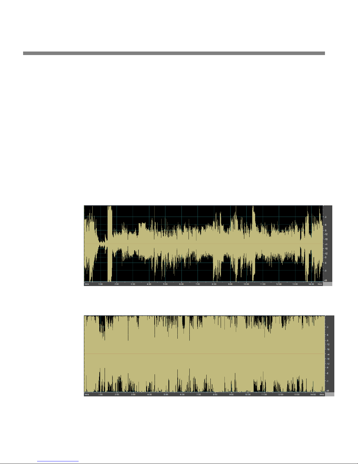
Figure 1-1: Unprocessed Audio
Figure 1-2: Same Audio Processed Through OPTIMOD-PC
Page 21
OPTIMOD-PC INTRODUCTION
being more powerful than its competition. We expect that the same subliminal psychology will hold in netcasting too.
Figure 1-1 shows a 15-minute snapshot of program audio as it emerged from the onair mixer of a major Los Angeles radio station. Source material included music,
speech, and commercials. Notice the large inconsistency in peak and average level
between one program source and the next. Figure 1-2 shows the same material after being processed through OPTIMOD-PC, using the G
REGG preset. Notice that pro-
gram levels are now consistent from source to source
Audio Processing for Netcasts
Professional-grade netcasting requires audio processing similar to FM broadcast (although there are some important differences in the peak limiting because of the
different characteristics of the pre-emphasized FM channel and the perceptually
coded netcasting channel). Your listeners deserve to get the best quality and consistency you can provide. Good audio processing is one important thing that separates
the amateur from the professional.
Conventional AM, FM, or TV audio processors that employ pre-emphasis/deemphasis and/or clipping peak limiters do not work well with perceptual audio coders such as Orban’s Opticodec-PC® MPEG4 AAC/aacPlusV2 streaming encoder. The
pre-emphasis/de-emphasis limiting in these processors unnecessarily limits high frequency headroom. Further, their clipping limiters create high frequency components—distortion—that the perceptual audio coders would otherwise not encode.
None of these devices has the full set of audio and control features found in Optimod-PC.
Peak clipping sounds bad even in uncompressed digital channels because these
channels do not rely on pre-emphasis/de-emphasis to reduce audible distortion. Instead of peak clipping, OPTIMOD-PC uses look-ahead limiting to protect the following channel from peak overload.
Measuring Studio and Transmission Levels
1-3
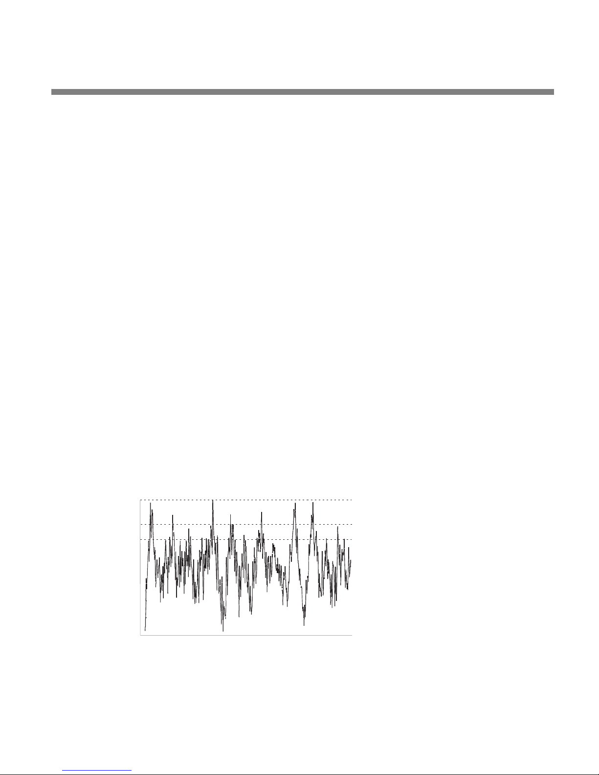
Figure 1-3: Absolute Peak Level, VU and PPM Reading
Studio equipment (like mixers) and transmission equipment (like codecs) typically
use different methods of metering to display audio levels. The VU meter is an aver-
ABSOLUTE PEAK
PPM
VU
Page 22

1-4
INTRODUCTION ORBAN MODEL 1101
age-responding meter (measuring the approximate RMS level) with a 300ms rise
time and decay time; the VU indication usually under-indicates the true peak level
by 8 to 14 dB. The Peak Program Meter (PPM) indicates a level between RMS and
the actual peak. The PPM has an attack time of 10ms, slow enough to cause the meter to ignore narrow peaks and under-indicate the true peak level by 5 dB or more.
The absolute peak-sensing meter (the type most common in codecs) shows the true
peak level. It has an instantaneous attack time, and a release time slow enough to
allow the engineer to read the peak level easily. All of OPTIMOD-PC’s level meters
are absolute peak sensing.
Figure 1-3 shows the relative difference between the absolute peak level and the
indications of a VU meter and a PPM for a few seconds of music program.
The studio engineer is primarily concerned with calibrating the equipment to provide the required input level for proper operation of each device, and so that all devices operate with the same input and output levels. This facilitates patching devices
in and out without recalibration and ensures that no part of the program chain will
clip the audio.
For line-up, the studio engineer uses a calibration tone at a studio standard level,
commonly called line-up level, reference level, or operating level. Metering at the
studio is by a VU meter or PPM. As discussed above, the VU or PPM indication underindicates the true peak level. So the studio standardizes on a maximum program
indication on the meter that is lower than the clipping level, so those peaks that the
meter does not indicate will not be clipped. Line-up level is usually at this same
maximum meter indication.
In facilities that use VU meters, this level is usually at 0 VU, which corresponds to the
studio standard level, typically +4 dBu. For facilities using +4 dBu standard level, instantaneous peaks can reach +18 dBu or higher (particularly if the operator overdrives the mixer). OPTIMOD-PC’s analog input clips at an instantaneous peak level of
+20 dBu, which provides 16 dB of headroom above a +4 dBu line-up level.
In facilities that use the BBC-standard PPM, maximum program level is usually PPM4
for music and PPM6 for speech. Line-up level is usually PPM4, which corresponds to
+4 dBu. Instantaneous peaks will reach +17 dBu or more on voice. In facilities that
use PPMs that indicate level directly in dBu, maximum program and line-up level is
often +6 dBu. Instantaneous peaks will reach +11 dBu or more.
Controlling Program Levels in a Playout System before OPTIMOD-PC
To optimize the consistency of a broadcast or netcast, preprocessing each program
element via OPTIMOD-PC before it is stored on a playout system is not as effective as
processing the playout system’s output in real time using OPTIMOD-PC. The latter
technique maximizes the smoothness of transition between program elements and
makes voice from announcers or presenters merge smoothly into the program flow,
even if the announcer is talking over music.
You can help OPTIMOD-PC operate at its best by setting the level of each program
element when you load it into the playout system. Many audio editing programs
permit a sound file to be “peak-normalized,” which amplifies or attenuates the level
of the file to force the highest instantaneous peak to reach 0 dBfs. This is a very
Page 23

OPTIMOD-PC INTRODUCTION
poor way to set the levels of different audio files on a playout system. Absolute
peak levels have nothing to do with loudness, so peak-normalized files are likely to
have widely varying loudness levels depending on the typical peak-to-average ratio
of the audio in the file. Because of over-use of peak limiting in today’s CD mastering
(which has the unfortunate side-effect of sucking the life and punch out of music),
the average level of a CD produced in the ‘80s can be as much as 15 dB lower than
the average level of a CD produced today. When a playout system segues two such
disparate peak-normalized files, this can cause audible loudness inconsistencies in
your broadcast/netcast while OPTIMOD-PC’s AGC section corrects the loudness.
OPTIMOD-PC’s AGC section uses window-gating technology to minimize the audibility of such gain riding. Even so, 15 dB of level correction can take several seconds
and is determined by OPTIMOD-PC’s AGC release time setting.
It is far better to normalize levels in a playout system by making the average levels
of all elements identical, which means that they would all peak at the same level
when observed with a VU meter. This allows OPTIMOD-PC’s AGC to work as unobtrusively as possible. Moreover, if your system includes locally originated speech material, using a microphone processor (like the dbx 286A) will help smooth the transition between live and recorded program segments.
1-5
The OPTIMOD-PC Digital Audio Processor
OPTIMOD-PC is a PCI card that fits in an IBM-compatible PC and processes one stereo
audio stream or two mono audio streams. It is equally suitable for netcasts and digital radio or television broadcasting. With its supplied WAVE drivers, it looks like a
standard sound card to your native applications, like the Orban’s Opticodec-PC®
MPEG4 AAC/aacPlusV2 streaming encoder. However, unlike a sound card, OPTIMODPC packs hundreds of MIPS of built-in DSP processing power, allowing it to apply
broadcast-quality audio processing to your netcast or digital broadcast without
loading down your computer’s CPU with DSP tasks.
OPTIMOD-PC is useful for users with multiple streams because you can load one
computer (which may be connected to a PCI expansion chassis) with as many
OPTIMOD-PC cards as you have free PCI slots, each card handling one stereo program. Each card has two AES3 or SPDIF digital inputs and one high-quality analog
input, all of which can be mixed—built-in sample rate converters allow digital
sources to be asynchronous. The card also offers an AES3 output and an analog
monitor output. Therefore, you can route audio through the computer’s PCI bus or
entirely independently of the computer—the choice is yours, and will depend on
your application. For example, DAB multiplexes can use multiple OPTIMOD-PC cards
to save cost and space by comparison to stand-alone processors. (The multiplexes
would use OPTIMOD-PC’s AES3 inputs and outputs, and could exploit OPTIMOD-PC’s
ability to genlock its output sample rate to the sample rate applied to either AES3
input.) OPTIMOD-PC (including the I/O mixer) is also fully remote controllable over a
network.
The rest of Chapter 1 explains how OPTIMOD-PC fits into the DAB and DTV broadcast facilities, and how it can be used for netcasting. Chapter 2 explains how to in-
Page 24

1-6
INTRODUCTION ORBAN MODEL 1101
stall it. Chapter 3 tells how to operate OPTIMOD-PC and tune it to get the sound
you want.
OPTIMOD-PC was designed to deliver a high quality sound while simultaneously increasing the average level on the channel substantially beyond that achievable by
“recording studio”-style compressors and limiters. Because such processing can exaggerate flaws in the source material, it is very important that the source audio be
as clean as possible.
For best results, feed OPTIMOD-PC unprocessed audio. No other audio processing is necessary or desirable.
In digital radio applications, if you wish to place level protection prior to your studio/transmitter link (STL), use an Orban studio AGC like the Orban 8200ST. The
8200ST can be adjusted so that it substitutes for the broadband AGC circuitry in
OPTIMOD-PC, which is then defeated. Other types of AGC systems may adversely
affect the audio.
General Features
• Orban Optimod-FM® 8500HD-class digital audio processing on a PCI sound
card—pre-processes audio for consistency and loudness before it is transmitted
or recorded.
• Applications include netcasting, HD Radio® (both primary and secondary digi-
tal channels), DAB and other dedicated digital radio services, FMExtra™ and
other digital subcarriers, mastering, audio production, and many others.
• Orban’s PreCode™ technology manipulates several aspects of the audio to
minimize artifacts caused by low bitrate codecs, ensuring consistent loudness
and texture from one source to the next. PreCode includes special audio band
detection algorithms that are energy and spectrum aware. This can improve codec performance on some codecs by reducing audio processing induced codec
artifacts, even with program material that has been preprocessed by other processing than Optimod.
• While primarily oriented toward “flat” media, Optimod-PC can also provide
preemphasis limiting for the two standard preemphasis curves of 50µs and
75µs. This allows it to protect preemphasized satellite uplinks and similar channels where protection limiting or light processing is required.
Because its processing topology is most effective with “flat media,” Optimod-PC cannot provide extreme loudness for preemphasized radio
channels. Use one of Orban’s Optimod-FM processors for this application.
For analog television with FM aural carrier(s), use Optimod-TV 8382.
Page 25

OPTIMOD-PC INTRODUCTION
• Two-Band automatic gain control with window gating and selectable L/R or
sum/difference processing compensates for widely varying input levels.
• Shelving bass equalizer and three-band parametric equalizer let you color
the audio to your exact requirements.
• Low-IM look-ahead limiter effectively limits peaks while ensuring that low-
bit-rate codecs operate optimally without overload.
• Optimod-PC’s dual-mono architecture allows entirely separate mono programs
to be processed in 5-band mode, facilitating dual-language operation.
In this mode, both processing channels operate using the same processing parameters (like release time); you cannot adjust the two channels to
provide different processing textures. See Dual-Mono Architecture on
page 3-8.
• Two AES3 or SPDIF digital inputs with high-quality sample rate conversion
allow two asynchronous digital sources to be mixed: Ideal for network operations using local commercial/announcement insertion.
1-7
• The second digital input also accepts AES3 house sync, synchronizing the AES3
output sample rate to the sample rate of the sync input.
• Digital inputs accept any sample rate from 32 to 96 kHz without manual con-
figuration.
• Balanced analog input with 24-bit A/D converter is always active, mixing with
the two digital inputs.
• Wave input from any PC audio application (like a playout system) that can emit
audio. Audio from the Wave input can be mixed and switched with OPTIMODPC’s hardware inputs.
• Wave output to any PC audio application that can record or encode.
• Supplied WAVE drivers allow OPTIMOD-PC’s processed output to pass through
the PCI bus to the CPU, driving standard PC applications, like Microsoft or Real
streaming encoders. The driver (with the aid of concurrently running third-party
software) also allows OPTIMOD-PC to receive audio over IP from the host computer’s network connection. Drivers are available for 32 and 64-bit Windows
XP as well as 32 and 64-bit Windows Vista.
• Full PCI bus-mastering with optimization.
• I/O Mixer application permits versatile routing and switching of processed and
unprocessed audio from and to OPTIMOD-PC’s inputs and outputs, and to and
from the host computer’s WAVE audio.
Page 26

1-8
INTRODUCTION ORBAN MODEL 1101
• Terminal Control API for network or localhost control and automation of all
I/O Mixer functions and Preset switching.
• MS Windows Mixer API support in parallel to the existing Orban Mixer allows
standard Microsoft Windows audio applications to control Optimod PC’s inputs
and outputs.
• MS Windows Metering API so Windows applications using this API will display
audio levels. (Many broadcast playout systems use this.)
• Serial port protocol allows Optimod-PC to be controlled either by ASCII serial
commands or by a serial-to–contact-closure device such as a Broadcast Tools SRC-
16.
• Balanced analog monitor output with 24-bit D/A converter.
• Precisely controls peak levels to prevent overmodulation or codec overload.
The peak limiter can be set up to control “flat” transmission channels or channels preemphasized at 50µs or 75µs.
• Internal processing occurs at 48 kHz sample rate and 20 kHz audio bandwidth.
• Two AES3 digital outputs at 32, 44.1, 48, 88.2, or 96 kHz sample rate. In v1.0
software, these emit identical signals.
• OPTIMOD-PC controls the audio bandwidth as necessary to accommodate the
transmitted sample frequency, obviating the need for extra, overshooting antialiasing filters in downstream equipment. OPTIMOD-PC’s high frequency bandwidth can be switched instantly (typically in 1 kHz increments) between 10.0 kHz
and 20 kHz. 20 kHz is used for highest-quality systems. 15 kHz meets the requirements of the iBiquity® HD-AM system that use 44.1 kHz system input sample frequency. (15 kHz codec bandwidth may also help low bitrate lossy codecs
sound better than they do when fed full 20 kHz bandwidth audio.) 10 kHz
bandwidth meets the requirements of auxiliary DAB transmissions using a 24
kHz sample frequency.
• Three Motorola DSPs do all the audio processing—there is no extra DSP load
on your computer’s CPU.
• Full coprocessing (independent of the CPU) means that audio will ordinarily
continue to pass through the card from its hardware inputs to its hardware outputs even if the host computer crashes. (Of course, WAVE inputs and outputs
will stop working because these are dependent on operating system services.)
• OPTIMOD-PC ships with over twenty standard presets, which correspond to
different programming formats. These presets have already been tested and
field-proven in major-market radio netcasting, digital radio, and direct satellite
Page 27

OPTIMOD-PC INTRODUCTION
broadcasting applications (both radio and television) worldwide. There are also
special-purpose presets for studio AGC, pure peak limiting, and low bitrate encoding applications.
• An easy-to-use graphic control application runs on your PC and can act as a
client to control any number of OPTIMOD-PC cards, either locally or in other PCs
on your network via TCP/IP addressing. Other Orban software offers a server
function, allowing other computers on your network to address cards located in
your PC. (This server software is installed automatically as part of the OPTIMODPC installation process and runs as a Windows service.)
• The Control application allows you complete flexibility to create your own cus-
tom presets, to save as many as you want to your local hard drive, and to recall
them at will.
Adaptability through Multiple Audio Processing
Structures
1-9
• A processing structure is a program that operates as a complete audio proc-
essing system. Only one processing structure can be active at a time. Just as there
are many possible ways of configuring a processing system using analog components (such as equalizers, compressors, limiters, and clippers), there are many
possible processing structures achievable by OPTIMOD-PC. OPTIMOD-PC realizes
its processing structures as a series of high-speed mathematical computations
made by Digital Signal Processing (DSP) chips.
• OPTIMOD-PC features two processing structures: Five-Band (or Multiband) for a
consistent, “processed” sound, free from undesirable side effects and Two-Band
for a tastefully controlled sound that preserves the frequency balance of the
original program material.
• The Two-Band structure can also be tuned to operate as a Protection Limiter,
providing up to 25dB of safety limiting with minimal side effects.
• OPTIMOD-PC can increase the density and loudness of the program material
by multiband compression and look-ahead limiting, improving the consistency of
the station’s sound and increasing loudness and definition remarkably, without
producing unpleasant side effects.
• OPTIMOD-PC rides gain over an adjustable range of up to 25dB, compressing
dynamic range and compensating for operator gain-riding errors and for gain
inconsistencies in automated systems.
• OPTIMOD-PC’s processing structures are all phase-linear to maximize audible
transparency.
Page 28

1-10
INTRODUCTION ORBAN MODEL 1101
• OPTIMOD-PC can be changed from one processing structure to another with a
smooth cross-fade.
• Two-Band automatic gain control with window gating and selectable L/R or
sum/difference processing compensates for widely varying input levels.
• Shelving bass equalizer and three-band parametric equalizer let you color
the audio to your exact requirements.
• Low-IM look-ahead limiter effectively limits peaks while ensuring that low-
bit-rate codecs operate optimally without overload.
• A pure peak limiting preset is available. It allows the 1101 to perform very high
quality peak limiting in mastering applications.
• OPTIMOD-PC can be used as a studio AGC (including peak limiting) to protect a
studio-to-transmitter link (STL), optimally using the STL’s native dynamic range.
Presets in OPTIMOD-PC
There are two kinds of presets in OPTIMOD-PC: Factory Processing Presets and User
Presets.
Factory Processing Presets
There are over 20 Factory Processing Presets. These are our recommended settings
for various program formats or types. The description indicates the processing structure and the type of processing. Each Factory Processing Preset on the Open Preset
list is really a library of 20 separate presets, selected by using the
to adjust OPTIMOD-PC for less or more processing.
Factory Processing Presets are stored as text files on the hard drive of the
same computer that houses the OPTIMOD-PC card. After an OPTIMOD PC
card is installed in your PC, a Presets folder containing all the factory and
user Preset files is created on your hard drive.
Each set of preset files consists on one “master” file and several
“less/more” files. Master files contain the preset data that is first loaded
when you activate a factory preset. Less/more files contain the preset
data that is called up when you edit a factory preset via the Control application’s one-knob “less/more” editing procedure. If there is no
less/more file for the less-more setting you choose, OPTIMOD-PC will
automatically generate the data by interpolating between the contents
of the two nearest less/more files.
The suffix of the master Factory preset files is ORBF11. Within the preset
folder on your hard drive, there is a corresponding less/more folder
LESS-MORE control
Page 29

OPTIMOD-PC INTRODUCTION
1-11
named after the master factory preset file. The Less/More files are located
in these folders. The file names of the less/more files are [preset name]
LMxxx.ORBF11, where “xxx” is three numbers, like “080” (which corresponds to a LESS/MORE value of 8.0). All of these files have been given
the “read-only” attribute to make them inconvenient to erase, even at
the operating system level. You cannot erase or overwrite them from the
OPTIMOD-PC Control application. If you erase or modify a factory or
less/more file from an external file manager like Windows Explorer (a
very unwise thing to do), you will have to reinstall the Optimod-PC software to regenerate the file unless you have a backup copy of the file
elsewhere.
The normal location for factory presets is
Files\Orban\OPTIMOD-PC2\presets
folder containing all of the less/more files for that preset. The less/more
folders are located immediately below the
folder bears the name of its associated preset.
There is only one copy of the factory presets per computer, regardless of
the number of OPTIMOD-PC cards installed in that computer.
. Each factory preset has an associated
presets folder; each less/more
c:\Program
You can create custom “factory” presets that have full LESS-MORE functionality. See
Creating Custom “Factory” Presets on page 3-57.
User Processing Presets
You can change the settings of a Factory Processing Preset, but if you want to preserve your changes, you must then store those settings as a User Preset, which you
are free to name as you wish. User presets can also be created by editing existing
user presets and saving the results under a new name.
The suffix of User Presets is
Optimod-PC 1101 v1.0 is compatible with presets created by Optimod-PC
1100 v2.0 or later. Because of the major structural changes in the DSP
processing between Optimod-PC 1100 version 1.x and version 2.x, user
presets created under version 1.x cannot be loaded into Optimod-PC
1100 with version 2+ software and cannot be loaded into the 1101. Because of the improvements between 1100 v1.0 and v2.0, it is often
worthwhile to create new user presets for the 1100 and 1101.
The suffix of 1100 version 1.x user presets is
You can store as many User Presets as the OPTIMOD-PC card’s host computer hard
drive and operating system can accommodate. User Presets are shown on the “Open
Preset” list by the name that you gave them when you saved them.
You can name them as you wish, limited only by the file naming limits in your operating system.
ORB11USER. The Factory preset remains unchanged.
ORBU.
Do not use a suffix; .ORB11USER will be added automatically.
The default folder containing User Presets for a given OPTIMOD-PC card is
c:\Program Files\Orban\OPTIMOD-PC2\[card serial number]\presets. A user
preset that you create while working with a given card is available only for that
Page 30

1-12
INTRODUCTION ORBAN MODEL 1101
card. To make the preset available to a second card, copy the preset file to the appropriate presets folder located under the second card’s serial number.
If you want to back up a user preset, use the standard Windows file copy mechanism
to copy it from its current folder into a backup folder you have made.
If you want to delete a user preset, use Windows to delete the preset’s associated
*.ORB11USER file.
User Presets cannot be created from scratch. Start by recalling a Factory preset. You
can then immediately store this in a new User Preset (with “Save As” from the FILE
menu), give it whatever name you wish, make changes to the settings as desired,
and then save it again. Alternatively, you can recall a Factory preset, make the
changes first, and then store this as a User Preset. Either way, the Factory preset remains for you to return to if you wish.
You can also modify an existing User Preset.
When you modify an existing preset, whether Factory or User, the
OPTIMOD-PC server software will automatically generate a temporary
User Preset whose name consists of “Modified” appended to the front of
the existing preset name. If you do not save your modifications, this temporary preset will remain on the server’s hard drive until you further
modify any preset. Then the temporary preset will be overwritten.
Input/Output Configuration
OPTIMOD-PC simultaneously accommodates:
• Two digital AES3 left/right outputs.
• Two digital AES3 left/right inputs, either of which can be used as a sync input to
synchronize the output sample rate emitted from the AES3 output to the sample
rate present at the sync input.
The output sample rate can also be synchronized to OPTIMOD-PC’s internal clock.)
• One set of analog left/right inputs and outputs.
The AES3 inputs and outputs and the analog input and output appear on
a female DB-25 connector on the rear of the card (see Figure 2-2 on page
2-4). Orban offers three variations of an “umbilical” cable that plugs into
the connector—one variation is terminated with XLR connectors, one is
terminated with RCA phono plugs, and one is unterminated.
Page 31
OPTIMOD-PC INTRODUCTION
1-13
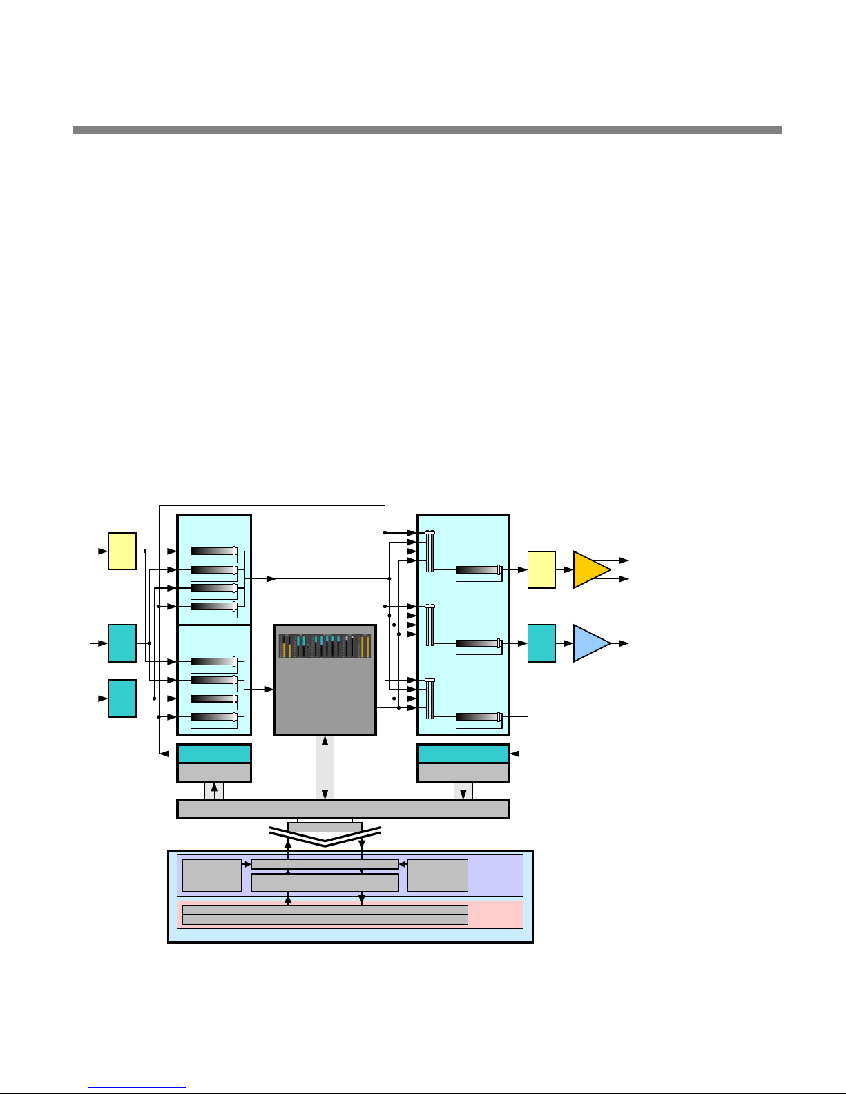
• Inputs and outputs passing through the computer’s PCI bus, using operating sys-
tem multimedia sound drivers, such as Microsoft Windows DirectSound WDM
WAVE drivers.
These inputs and outputs are controlled by the OPTIMOD-PC Mixer application, which can be launched from the Tools menu on the OPTIMOD-PC
control application, and can also be remotely accessed.
Digital AES3 Left/Right Input/Output
The digital inputs and outputs follow the professional AES3 hardware standard regarding impedances and levels, although their data streams can also be configured
to follow the consumer SPDIF standard.
In most practical situations, AES3 and SPDIF are interchangeable and can
be interoperated with each other without difficulty; you usually do not
have to concern yourself with which standard you are using. Generally, if
the equipment to which you are connecting has pin jacks, set OPTIMODPC to use the SPDIF standard. If the equipment has XLR-type connectors
ADC
SRC
DIRECT
MIXER
Analog IN
Digital IN 1
Digital IN 2
Wave OUT
PROCESSOR
MIXER
Analog IN
Digital IN 1
Digital IN 2
Wave OUT
SRC SRC
From Wave App OUT To Wave App IN
Optimod-PC
Control
Application
LOCAL CONTROL
Player/Decoder Applications Recorder/Encoder Application
OPTIMOD-PC
Processing
PCI Interface
PCI Bus
Optimod-PC WDM DirectSound Driver
Windows
Sound Out
Editor Application
Windows
Sound In
OUTPUT LEVELS
Direct Wave Out
Direct Out
Process Pre-Limit Out
Process Limit Out
Analog OUT
Direct Wave Out
Direct Out
Process Pre-Limit Out
Process Limit Out
Digital OUT
Direct Wave Out
Direct Out
Process Pre-Limit Out
Process Limit Out
Wave IN
Optimod-PC
Control
Service
REMOTE CONTROL
PC Software
Optimod-PC
Software
Application
Software
DAC
SRCSRC
AES
EBU
L
R
Analog
Output
Digital
Output
Figure 1-4: OPTIMOD-PC Signal Flow and I/O
Page 32

1-14
INTRODUCTION ORBAN MODEL 1101
or BNC connectors, set OPTIMOD-PC to use the AES3 standard.
OPTIMOD-PC incorporates an output sample rate converter that allows operation at
32, 44.1, 48, 88.1, or 96 kHz sample frequency. The inputs have sample rate converters that allow the input to accept any sample rate between 20 kHz and 96 kHz.
To ensure best control of peak modulation, operate the output at 48
kHz. This guarantees that the output samples are synchronous with the
peak-controlled samples produced by the processing.
If you have ordered the optional 1101/CBLXLR XLR-terminated cable assembly, then
the left/right digital inputs appear on two XLR-type female connectors on this cable.
The left/right digital output is on one XLR-type male connector on the cable. If a
given digital input is not being used to receive a digital audio input, it is available to
genlock OPTIMOD-PC’s output sample frequency to house sync, if required.
OPTIMOD-PC simultaneously accommodates WAVE, digital, and analog inputs and
outputs. You can mix all inputs into one signal that is applied to the processing. The
digital inputs can be asynchronous because both are applied to sample rate converters that lock them to OPTIMOD-PC’s internal 48 kHz sample frequency.
Level control of all inputs and outputs is via the OPTIMOD-PC Mixer application, including remote access.
Analog Left/Right Input/Output
The left and right analog inputs are on XLR-type female connectors on the umbilical
cable. Input impedance is greater than 10kΩ; balanced and floating. Inputs can accommodate up to +20dBu (0dBu = 0.775Vrms).
The left and right analog outputs are on XLR-type male connectors on the umbilical
cable. Output impedance is 50Ω, balanced and floating.
The outputs are intended for monitoring. They can drive 600Ω or higher impedances. However, they are AC-coupled with a –3dB frequency of approximately 1 Hz,
which is higher than the 0.15 Hz recommended by Orban to avoid low-frequency
overshoots (“bounce”) caused by phase shifts. Therefore, when you are using the
audio processing for peak control, such control will be noticeably poorer at the analog outputs than at the AES3 or WAVE outputs, both of which exhibit very tight
peak control. Consequently, you should always use OPTIMOD-PC’s AES3 or WAVE
outputs to drive your transmission chain.
For a more detailed diagram of the “Processor” block, see Figure 3-2: Simplified
OPTIMOD-PC Digital Signal Processing Diagram on page 3-9.
The Orban I/O Mixer
The I/O Mixer mixes and routes audio to and from the OPTIMOD-PC card.
(See Figure 1-4: OPTIMOD-PC Signal Flow and I/O on page 1-13, and Figure 1-5: Typi-
Page 33

OPTIMOD-PC INTRODUCTION
cal I/O mixer on page 1-16.) You can open the Optimod PC Mixer from the Tools
menu in the Orban Control application.
Within the Optimod PC Mixer, there are two mixers, each of which receives the same
four inputs:
• The stereo analog input on the DB-25 connector
• Digital 1 Input(AES3) on the DB-25 connector
• Digital 2 Input (AES3) on the DB-25 connector
• The WAVE Out from the computer operating system’s internal mixing and rout-
ing
The first “Processor Mixer” sends its output to the audio processing DSP on the
OPTIMOD-PC card.
The second “Direct Mixer” sends its output directly to the output routing switcher.
There are three outputs, each of which can receive the following four possible
sources:
1-15
• The Direct WAVE bitstream received from the computer.
• The Direct Mixer’s output.
• The processor without limiting: The output of the OPTIMOD-PC audio processing
that follows all processing except final peak limiting.
• The processor with limiting: The output of the OPTIMOD-PC audio processing
that follows all processing, including peak limiting.
Not all outputs have to receive the same source; any source can feed any
output.
Source (3) can provide low-delay monitoring into live talent headphones
because it has much lower throughput delay than source (4).
The output signal routing switcher determines which of the above four signals
feeds:
• the OPTIMOD-PC card’s stereo analog output
• the OPTIMOD-PC card’s AES3 digital output, and
• the WAVE In going to the PC.
Page 34
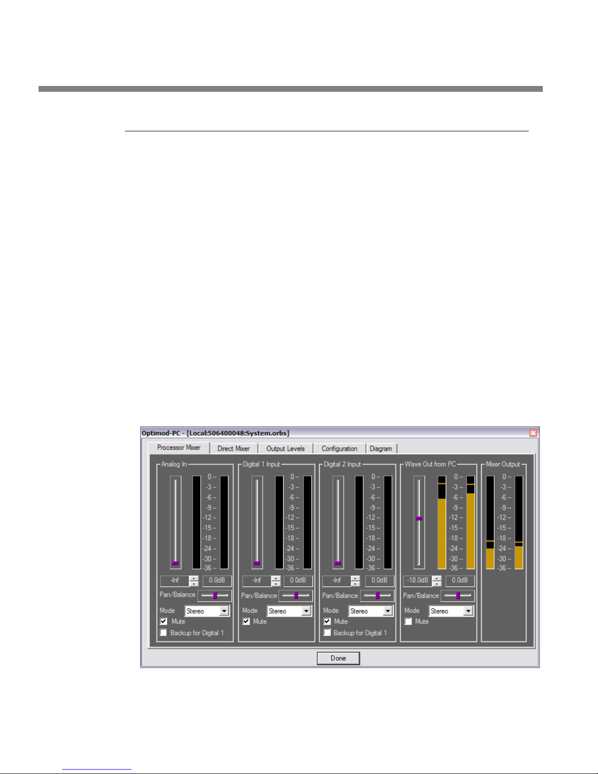
1-16
INTRODUCTION ORBAN MODEL 1101
Overview of an OPTIMOD-PC Installation
An OPTIMOD-PC card installs in a PCI slot in an IBM-compatible host computer. The
computer’s PCI bus must be Plug & Play PCI Version 2.2 compliant, 32-bit, 33MHz,
with a transfer rate up to 132MBytes/sec. OPTIMOD-PC will operate in a 3.3V or 5V
PCI slot, and with bus extenders.
Almost all recently manufactured PCs meet these PCI bus specifications.
OPTIMOD-PC is supported on Windows XP (SP2 or higher) and on Vista (SP1 or
higher) computers. It will usually work on Windows 2000 computers (SP4 or higher)
but Orban Customer Service does not support this platform. No other operating systems (such as Linux or Mac OS) will work.
OPTIMOD-PC’s driver is multi-client but will only support multiclient operation in a
Windows XP environment. Windows 2000, while compatible with OPTIMOD-PC’s
driver, only supports single-client operation.
Users who need to stream to multiple encoders from a single OPTIMODPC must use Windows XP.
More than one OPTIMOD-PC card can be installed in a given host computer. The
number of cards is limited only by the number of available PCI slots, which may reside in a PCI expansion chassis.
Conceptually, there are two options for operating OPTIMOD-PC: simple and net-
Figure 1-5: Typical I/O mixer
Page 35

OPTIMOD-PC INTRODUCTION
work (see Figure 2-1: OPTIMOD-PC Network Scenarios on page 2-3).
• Simple operation will only control OPTIMOD-PC cards that are installed in the
same PC that is running the Orban application.
• Network operation allows you to control one or more OPTIMOD-PC cards over a
network, regardless of whether the OPTIMOD-PC card is located in the controlling computer.
Both modes of operation require you to run a server application in the background
on any remote computer housing OPTIMOD-PC cards. However, you do not need to
run the server if you are running the Control Application in a computer that has no
OPTIMOD-PC cards installed.
In this case, the Control Application would be dedicated to controlling
OPTIMOD-PC cards located in other computers on the network.
The server is installed automatically when you install the OPTIMOD-PC software and
is configured to run as a “Windows Service.” The server application is an intermediary that enables the Orban Control Application to remotely communicate with the
OPTIMOD-PC card(s) installed in a given host computer. One instance of the server
application handles communications for all of the OPTIMOD-PC cards in a given host
computer. When the host computer is booted, the OPTIMOD-PC driver initializes the
DSP on the card, initializes the I/O settings, and sets the processor settings to a default value. After that, the OPTIMOD-PC server finishes starting up and then resets
the processing parameters and I/O settings to their previous power-down values.
The service completes this task just before the Windows Log-On screen appears.
The Control Application connects (through the server) to only one card at a time,
allowing you to recall, edit and save presets, set input/output mix levels, and do
other housekeeping tasks for that card.
Note that the Control Application does not use the server to interface
with a card installed on the same computer that is running the Control
Application.
1-17
“Simple” operation occurs when the Service’s remote server is disabled. For “network” operation, you may use the Optimod Control Application to set passwords at a given OPTIMOD-PC card’s host computer to protect it from unauthorized
access from the network. You also need to make your local cards visible to the network by selecting “Allow Network to Access Local Cards” in the “Card and Security
Administration” screen, which is accessible from the Tools drop down menu box.
The setup instructions in Section 2 of this manual provide detailed instructions on
how to do this.
In a Simple or Network environment, the number of OPTIMOD-PC cards that one
host can accommodate depends only on the number of free PCI slots available and
on the speed of the host’s CPU. (PCI expansion chassis are supported.) OPTIMOD-PC
cards share IRQs, so availability of IRQs will not usually be a problem.
Although OPTIMOD-PC contains on-board DSP, the host’s CPU must still perform
some “housekeeping” chores. It must run Orban’s server software, and, more significantly, it must do sample rate conversion if OPTIMOD-PC is used as a WAVE device
and the source or destination sample rates are different from 48 kHz. On the other
hand, if only OPTIMOD-PC’s analog input and/or AES3 digital I/O are used for input
Page 36

1-18
INTRODUCTION ORBAN MODEL 1101
and output, then OPTIMOD-PC’s built-in hardware sample rate converters do all necessary conversion and no extra load is placed on the host CPU for sample rate conversion.
Simple Operation in One Host Computer
When only one card is installed in a local machine, the OPTIMOD-PC control application running on said local machine will automatically connect to that card if you
start the application by clicking its “agent” icon, located in the far right side of the
Windows taskbar in the Windows system tray. (This icon looks like a loudspeaker
colored violet.) If more than one card is installed (or if you start the application any
other way than by clicking on the agent icon), the Control application will initialize
without connecting to a card and you must connect the application to the card you
wish to control.
When you first install OPTIMOD-PC on a computer, all cards are hidden from the
network by default. Consequently, “simple” operation is always the default in a
new installation. Simple operation makes sense in applications like a production
studio, where you are using the OPTIMOD-PC processing to master files for subsequent broadcast, streaming, or dissemination on other media like CD or DVD.
Security
OPTIMOD-PC is designed for networking. Because most PCs are now networked, the
cards must be protected from unauthorized access when networking is activated.
Two levels of security achieve this:
• Each card has a User password that allows an authorized user to “connect” to
the card via the OPTIMOD-PC Control Application. When this occurs, the user
can work with the audio processing functions in the card, can change and edit
presets, and can do other tasks similar to those that one would do on a standalone audio processor. Additionally, each card has a Terminal Password (operating at the User security level) that allows you to connect to a card via the
OPTIMOD-PC TCP/IP terminal server to allow external control of the OPTIMODPC cards from either a Telnet/SSH client or a custom third party application. See
Optimod-PC System/Mixer Control API on page 6-1.
• Each card has an Administrator password that allows an administrator to change
the name of the card, allow network access, change the Administrator password,
and change the User password from anywhere on the network.
Only an administrator can assign and change user passwords. If the user
has checked “remember password” on the dialog box requesting password entry, only the administrator can “uncheck” the “remember password” function for that card.
Unless networking is activated, cards located in a given machine are visible only to the Orban Control application running locally on that machine. They are invisible to other machines on the network. Not running
in “network” mode therefore provides considerable security.
Page 37

OPTIMOD-PC INTRODUCTION
• By creating a “Network Accept List,” you can specify which computers are per-
mitted to connect to a given OPTIMOD-PC. This provides a layer of security that
complements password protection. See step 7 on page 2-7.
Each OPTIMOD-PC has a unique serial number burned into its on-card ROM. It is also
written on a label on the card’s mounting flange so it can be seen from outside the
host computer. The serial number is the fundamental means by which the Orban
software identifies the card. When you first install your card(s), the card’s serial
number appears next to the profile name in the Connect drop-down box and at the
top left hand corner in the application when you are connected to that card.
The Optimod-PC serial number is appended to the Windows audio device name,
making it easier to keep track of multiple cards and their connections and allowing
reliable software security for the individual Opticodec-PC encoder software that uses
Optimod-PC as a hardware dongle.
The Orban software allows you to give a card an easily remembered name (e.g.,
“KORB”) so the software does not have to address the card by its serial number. This
name is an alias that is local to the computer from which you named the card; the
same card could be known by a different name on each computer in the network.
1-19
If you give your card an alias name, this name will appear (instead of the serial number) next to the profile name in the Connect drop-down box and at the top left
hand corner in the application when you are connected to that card.
Only the card’s serial number is unique. The serial number is always
available on “Card and Security Administration” screen, which is accessible from the Tools drop-down menu box.
Only an administrator can rename a card (profile), and that name will
remain only on the machine from which it was assigned that name.
For Orban’s Control application to access cards on other machines, those machines
must have Orban server software running (with “Allow Network to Access Local
Cards” checked in T
always know these remote cards’ passwords to access them. These passwords are
initially assigned by the administrator at the machine in which the remote cards are
installed. If you plan network operation, it is very important to assign both a User
and an Administrator password to each card in that machine to prevent the cards
from being hacked.
The dual password system is useful in protecting a networked installation
from being damaged by disgruntled employees or hackers who might
get access to a User password and server IP address. A malicious user
might set incorrect presets and audio levels, activate test tones, mute the
audio, or delete user presets. (This is another reason, other than potential
hard drive failure, why it is wise to back up user presets.)
However, a malicious user cannot take exclusive control of a card by
changing its name or password. Only an administrator can do that.
Meanwhile, the administrator can change User passwords and rename
cards from a central location. It is wise to do this each time a person with
OOLS/CARD & SECURITY ADMIN.) and the Control application must
Page 38

1-20
INTRODUCTION ORBAN MODEL 1101
a User password leaves the employ of the entity doing the streaming or
broadcasting—it’s like “changing the locks.”
No networked card outside the local machine is viewable inside Orban’s software
until you “add” it to the list of viewable cards by going into Connect>Add and then
supplying the IP address and the card’s User password (if a password was assigned to
that card). This allows one host computer to accommodate multiple OPTIMOD-PC
cards, each processing competitor’s streams, while allowing a given competitor to
view only its own card(s) from the Control application.
Networking OPTIMOD-PC Cards
Orban’s OPTIMOD-PC control application can control OPTIMOD-PC cards installed
anywhere on a TCP/IP network, including the Internet. A complex system (such as
one that a major broadcast group, or large server farm/ISP might operate) could
have dozens of clients and servers networked together. Each host computer has a
TCP/IP address and port assigned to it and runs an instance of the Orban server application.
The Orban Control application can automatically find all cards within a given host
computer anywhere on the network if the Control application knows the IP address
of the host computer. However, the Control application will leave the cards hidden
from the application’s user until the user “adds” the cards by supplying their User
passwords and IP addresses.
To connect to a card, you must first add the host computer/server to your control
application via C
vide the host computer’s IP address and port number. Once a profile/card is added,
you can connect to it by double-clicking on the card in the C
Each local copy of the Orban Control application allows you to name a server (e.g.,
“Boston”) so you do not have to remember its IP address and port number each
time you connect the Control application to it.
You can see a drop-down list of all cards that have been added previously, regardless of whether you are logged onto the host computer housing those cards. Once
you have logged onto the host computer, you can connect to any card on this list if
it is “available” (that is, if it is still installed in the host computer; removing a card
from its host computer will not automatically remove its name from a client computer). If you have not previously connected to a given card and specified “remember password,” you must supply your User password before you can connect.
ONNECT>ADD PROFILE/CARDS (step 10 on page 2-10). Here, you pro-
ONNECT drop-down list.
The server names are stored locally on each computer; each local copy of
the Orban Control application can create a different profile name for a
given server. A server’s real “name” is always its IP address and port.
Once you have specified “remember password,” the password dialog box
will not appear again and the “remember password” status can only be
canceled by an administrator. “Remember password” can compromise security, so you should use this feature with discretion.
Page 39

OPTIMOD-PC INTRODUCTION
Only one client can be logged into a given card at one time; the card will return “in
use” if another client attempts to log into the same card. However, more than one
client can be logged onto a given host computer at once, provided that each client is
logged onto a different card within that host.
It is it is unsafe to send commands to the API of a card within a given
computer while the Control Application is connected to that card via the
Control Application’s “Local” connection. This can create conflicts within
the OPTIMOD-PC software that could cause system instability. Moreover,
it is unsafe to simultaneously connect a local and remote instance of the
OPTIMOD-PC Control Application to a given OPTIMOD-PC card.
To resolve this issue safely and without any performance compromise, do
not use the Local connection. Instead, connect the Control Application to
a local card via a “localhost” TCP/IP connection. To do this, create a new
profile, following the instructions in step 10 on page 2-10. Use IP address
127.0.0.1 (localhost). Then connect the Control Application to the local
card as you would to any card residing in a remote computer (step 11on
page 2-12).
If you are not using the 1101’s API, it is OK to use the Local connection.
1-21
Section 2 of this manual provides detailed, systematic instructions for setting up a
network of OPTIMOD-PC cards.
Location of OPTIMOD-PC for Netcasting
It is usually best to locate OPTIMOD-PC cards in the same machine that runs the encoding software, like Orban OPTICODEC-PC, Microsoft Windows Media Encoder or
Real Networks HELIX Producer. This is because the output of the encoder is at a
much lower data rate than the audio used to drive the OPTIMOD-PC input(s), so it is
less expensive to transport encoded audio than unencoded audio. In Windows installations, the encoder receives the processed output of OPTIMOD-PC through the
standard Windows’ WAVE signal handling mechanism. You control mixing and routing through the OPTIMOD-PC I/O Mixer application, which you call from the
OOL>I/O MIXER menu item in the OPTIMOD-PC Control application.
T
OPTIMOD-PC’s digital inputs accept stereo pairs of uncompressed PCM-format digital audio. OPTIMOD-PC’s AES3 digital inputs will not accept “bitstream” inputs encoded with formats like Dolby Digital® or DTS®. Inputs must be two-channel “PCM”
(Pulse-Code Modulation) format with sample rates from 32 to 96 kHz and 8 to 24 bit
word length, following standard AES3 or SPDIF protocols. Because both digital inputs have sample rate converters, both inputs can be mixed (even if asynchronous
with each other) and neither need be synchronous with the output.
If the netcasting servers are located remotely, then there is a particular advantage
to transporting the compressed stream instead of the raw PCM. If the data rate of
the compressed stream is less than 128kbps, it can be transported on an ISDN line. If
the rate is greater, or if more than one stream is being transported, a fractional T1
line is often suitable. In general, IP connection via the Internet is insufficiently reliable for “broadcast contribution quality” connections, introducing a risk of gaps and
Page 40

1-22
INTRODUCTION ORBAN MODEL 1101
dropouts in the stream. Therefore, it is desirable to use an encoder (such as
OPTICODEC-PC) that can automatically reconnect to the server in the unlikely event
that the connection is dropped.
Genlocking OPTIMOD-PC Cards to a Reference Sample
Frequency
Many facilities have a reference sample frequency to which all digital equipment is
locked. While OPTIMOD-PC’s word clock input is not supported in 1101 v1.0 software (it will be supported in a future free software upgrade), either AES3 input can
accept a reference sample frequency via an AES3 or AES11 signal. OPTIMOD-PC’s
output sample frequency can then be locked to this reference [see step (4.B) on
page 2-22.]
This reference can be the sample frequency of one of the active audio inputs. On
the other hand, if you have an AES3 stream available exclusively as a sample frequency reference, you can then connect this stream to the input that you specify as
the “reference” and mute the reference input in the Orban I/O Mixer application.
(See Figure 1-4: OPTIMOD-PC Signal Flow and I/O on page 1-13, and Figure 1-5: Typi-
cal I/O mixer on page 1-16.)
Because of hardware limitations in the sample rate converters, input frames are not
necessarily phase-aligned to output frames according to the strictest interpretation
of the AES-11 standard. However, the sample frequency of the output will be identical to the sample frequency of the input. In addition, these limitations prevent the
passing of AES3 user bits from digital input to digital output.
Using OPTIMOD-PC’s internal crystal reference, you can also set the output sample
frequency to be independent of the input sample frequency. In this case, you can
freely set the output to 32, 44.1, 48, 88.2, or 96 kHz.
If the input reference sample frequency deviates from the preset output
sample frequency by more than ±4%, the output sample frequency will
lock automatically to OPTIMOD-PC’s internal crystal reference instead of
the input reference.
In all cases, OPTIMOD-PC’s internal processing operates at 48 kHz, locked
to OPTIMOD-PC’s internal crystal reference. The output sample rate converter, which is always in-line, determines the output sample rate.
Studio-Transmitter Link in Digital Broadcasting
The following information is mainly relevant to digital radio broadcasters who have
their transmitters and studios at different locations. It assumes that you are using
OPTIMOD-PC as a replacement for a stand-alone audio processor. In this context,
you use OPTIMOD-PC’s external analog or digital inputs and outputs and do not
route the audio through the host computer.
Page 41

OPTIMOD-PC INTRODUCTION
Most netcasters will not find the information in this section relevant because if netcasters need to ship audio beyond their LAN, they ordinarily ship it from one location to another in the form of encoded audio through low-capacity Telco-supplied
digital links like ISDN or E-1/T-1.
1-23
Transmission from Studio to Transmitter
There are five types of studio-transmitter links (STLs) in common use in broadcast
service: uncompressed digital, digital with lossy compression (like MPEG, Dolby
®
APT-x
video microwave STL.
STLs are used in two fundamentally different ways. Either they can pass unprocessed
audio for application to OPTIMOD-PC’s input or they can pass OPTIMOD-PC’s peakcontrolled output. The two applications have fundamentally different performance
requirements.
• A link that passes unprocessed audio should have very low noise and low non-
• A link that passes processed audio does not need as low a noise floor as a link
Digital links
Digital links may pass audio as straightforward PCM encoding, or they may apply
lossy data reduction processing to the signal to reduce the number of bits per second required for transmission through the digital link. Such processing will almost
invariably distort peak levels, and such links must therefore be carefully qualified
before you use them to carry the peak-controlled output of OPTIMOD-PC to the
transmitter. For example, the MPEG Layer 2 algorithm can increase peak levels up to
4dB at 160kb/sec by adding large amounts of quantization noise to the signal. While
the desired program material may psychoacoustically mask this noise, it is nevertheless large enough to affect peak levels severely. For any lossy compression system
the higher the data rate, the less the peak levels will be corrupted by added noise,
so use the highest data rate practical in your system.
), microwave, analog landline (telephone/post line), and audio subcarrier on a
At this writing, we believe that the Internet is insufficiently reliable to
serve as a carrier for a real-time STL because of the risk that network interruptions may randomly interrupt the audio feed.
linear distortion, but its transient response is not important.
passing unprocessed audio. However, its transient response is critical. In DAB applications, such a link must be uncompressed digital and must use digital inputs
and outputs to achieve best results. We will elaborate below.
®
, or
It is practical (though not ideal) to use lossy data reduction to pass unprocessed audio to OPTIMOD-PC’s input. The data rate should be at least of “contribution quality”—the higher, the better. If any part of the studio chain is analog, we recommend
using at least 20-bit A/D conversion before encoding.
Because OPTIMOD-PC uses multiband limiting, it can dynamically change the frequency response of the channel. This can violate the psychoacoustic masking assumptions made in designing the lossy data reduction algorithm. Therefore, you
Page 42

1-24
INTRODUCTION ORBAN MODEL 1101
should leave “headroom” in the algorithm so that OPTIMOD-PC’s multiband processing will not unmask quantization noise. This is also true of any lossy data reduction applied in the studio (such as hard disk digital delivery systems).
For MPEG Layer 2 encoding, we recommend 384 kb/second or higher.
Some links may use straightforward PCM (pulse-code modulation) without lossy
data reduction. If you connect to these through an AES3 digital interface, these can
be very transparent, provided they do not truncate the digital words produced by
the devices driving their inputs and they do not require downward sample rate conversion.
Downward sample rate conversion can cause overshoot due to spectral
truncation and asynchronous re-sampling of the 48 kHz peak-controlled
samples.
If the link does not have an AES3 input, you must drive its analog input from
OPTIMOD-PC’s monitor output. This is not recommended because OPTIMOD-PC’s
monitor output will overshoot in the analog domain because of the physics of the
system. For many of the same reasons, avoid using external digital-to-analog converters.
Peak control in OPTIMOD-PC occurs at a 48 kHz sample frequency. This is
sufficient to prevent any samples from exceeding the threshold of limiting. However, after reconstruction, the analog output may overshoot the
nominal 100% level because these overshoots “fall between the samples,” so the processing cannot be aware of them. If you use this output
to feed the analog input of a digital STL, the new samples in the STL will
not be synchronous with the samples inside OPTIMOD-PC. Therefore,
they may well fall on the overshoots, causing loss of peak modulation
control. It is thus important to use a link with an AES3 input to ensure
correct peak control.
The same sort of thing can happen if you use the output sample rate
converter, because the output samples are no longer synchronous with
the peak-controlled samples in the processing. Always use 48 kHz output
sample rate to achieve best peak control.
If you must use an analog input, you may bypass any anti-aliasing filters
in digital links driven by OPTIMOD-PC because OPTIMOD-PC’s output
spectrum is tightly controlled. This ensures the most accurate possible
transient response, given the limitations of asynchronous sampling described above.
Using analog outputs or non-48kHz sample rates will seldom introduce
more than 0.5 dB of overshoot, so it is usually sufficient to allow 0.5 dB
of headroom in these non-ideal setups. For example, one would set
OPTIMOD-PC’s digital output level to –0.5 dB to prevent clipping.
NICAM is a sort of hybrid between PCM and lossy data reduction systems. It uses a
block-companded floating-point representation of the signal with J.17 preemphasis.
Older technology converters (including some older NICAM encoders) may exhibit
quantization distortion unless they have been correctly dithered. Additionally, they
can exhibit rapid changes in group delay around cut-off because their analog filters
Page 43

OPTIMOD-PC INTRODUCTION
are ordinarily not group-delay equalized. The installing engineer should be aware of
all of these potential problems when designing a transmission system.
You can minimize any problems by always driving a digital STL with OPTIMOD-PC’s
AES3 digital output, which will provide the most accurate interface to the STL. The
digital input and output accommodate sample rates of 32 kHz, 44.1 kHz, 48, 88.2,
and 96 kHz.
Some NICAM hardware is known to have inadequate low frequency response, compromising peak control if OPTIMOD-PC’s processed output is passed through this
hardware. Such hardware should be tested and qualified.
Microwave STLs
In general, an analog microwave STL provides high audio quality as long as there is a
line-of-sight transmission path from studio to transmitter of less than 10 miles (16
km). If not, RF signal-to-noise ratio, multipath distortion, and diffraction effects can
cause serious quality problems. However, the noise and non-linear distortion characteristics of such links are likely to be notably poorer than 16-bit digital even if
propagation conditions are ideal.
1-25
As discussed above, asynchronous resampling will cause overshoots if any analog
path (even a perfectly transparent one) passes OPTIMOD-PC’s processed output to
the transmitter. Lack of transparency in the analog path will cause even more overshoot. Unless carefully designed, microwave STLs can introduce non-constant group
delay in the audio spectrum, distorting peak levels when used to pass processed audio. Nevertheless, in a system using a microwave STL, OPTIMOD-PC is sometimes located at the studio and any overshoots induced by the link are tolerated or removed
by the transmitter’s protection limiter (if any). OPTIMOD-PC can only be located at
the transmitter if the signal-to-noise ratio of the STL is good enough to pass unprocessed audio. The signal-to-noise ratio of the STL can be used optimally if an
Orban Studio AGC, another OPTIMOD-PC, or an Orban Transmission Limiter protects
the link from overload.
If OPTIMOD-PC is located at the transmitter and receives unprocessed audio from a
microwave STL, it may be useful to use a companding-type noise reduction system
(like dbx Type 2 or Dolby SR) around the link. This will minimize any audible noise
buildup caused by compression within OPTIMOD-PC.
Some microwave links may be modified such that the deviation from linear phase is
less than +
and less than 0.1dB down at 20 kHz. This specification results in less than 1% overshoot with processed audio. Many such links have been designed to be easily configured at the factory for composite operation, where an entire FM stereo baseband
is passed. The requirements for maintaining stereo separation in composite operation are similar to the requirements for high waveform fidelity with low overshoot.
Therefore, most links have the potential for excellent waveform fidelity if they are
configured for composite operation (even if a composite FM stereo signal is not actually being applied to the link).
10° 20-20 kHz, and frequency response is less than 3dB down at 0.15Hz
Page 44

1-26
INTRODUCTION ORBAN MODEL 1101
Further, it is not unusual for a microwave STL to bounce because of a large infrasonic peak in its frequency response caused by an under-damped automatic frequency control (AFC) phase-locked loop. This bounce can increase the STL’s peak carrier deviation by as much as 2dB, reducing average modulation. Many commercial
STLs have this problem.
Some consultants presently offer modifications to minimize or eliminate this problem. If your exciter or STL has this problem, you may contact Orban Customer Service
for the latest information on such services.
Analog Telephone/Landline (PTT/Post Office Line)
Analog landline quality is extremely variable, ranging from excellent to poor. (Fortunately, they are largely obsolete, having been replaced by digital links.) Whether
landlines should be used or not depends upon the quality of the lines locally available, and upon the availability of other alternatives. Due to line equalizer characteristics and phase shifts, even the best landlines tend to veil audio quality slightly.
They will certainly be the weakest link in a DAB broadcast chain.
Slight frequency response irregularities and non-constant group delay characteristics
will alter the peak-to-average ratio, and will thus reduce the effectiveness of any
peak limiting performed prior to their inputs.
Location of OPTIMOD-PC in Digital Radio Service
At the Transmitter is Best
The best location for OPTIMOD-PC is as close as possible to the transmitter so that
OPTIMOD-PC’s AES3 output can be connected to the transmitter through a circuit
path that introduces no change in OPTIMOD-PC’s output bitstream. A high-quality
AES3 cable is ideal.
Where Access to the Transmitter is not Possible
Sometimes it is not possible to locate OPTIMOD-PC at the transmitter. Instead, it
must be located on the studio side of the link connecting the audio facility to the
transmitter. If the transmitter is not accessible, all audio processing must be done at
the studio, and you must tolerate any damage that occurs later.
If an uncompressed digital link is available, this is an ideal situation because such a
link will pass OPTIMOD-PC’s output with little or no degradation. However, such a
link is not always available.
If only a 32 kHz sample rate link is available, the sample rate conversion
necessary to downsample the audio will cause overshoots when
OPTIMOD-PC is operated at 20 kHz bandwidth because the sample rate
converter removes spectral energy. In this case, you can minimize overshoot by operating OPTIMOD-PC at 15 kHz bandwidth. (Set it from the
ONFIGURATION tab in the I/O Mixer application.)
C
Unless the path is a digital path using no lossy compression, this situation will yield
lower performance than if OPTIMOD-PC is connected directly to the transmitter be-
Page 45

OPTIMOD-PC INTRODUCTION
cause artifacts that cannot be controlled by OPTIMOD-PC will be introduced by the
link to the transmitter. These artifacts can decrease average modulation by 2-4dB
and can also add noise and audible non-linear distortion. In the case of lossy digital
compression, this deterioration will be directly related to the bitrate. For an analog
path, the deterioration will depend on the amount of linear and non-linear distortion in the path. In addition, there will be an unavoidable amount of overshoot
caused by asynchronous re-sampling (see page 1-24).
One strategy is to apply to OPTIMOD-PC’s output signal the same lossy compression
that the DAB transmitter would apply. If a digital link is available with sufficient bitrate to pass this compressed signal, it can then be passed directly to the DAB transmitter without further processing if synchronization issues can be resolved. Consult
with the manufacturer of your DAB transmitter to see if this can be done.
Where only an analog or lossy digital link is available, feed the audio output of
OPTIMOD-PC directly into the link. If available, the transmitter’s protection limiter
should be adjusted so that audio is normally just below the threshold of limiting:
The transmitter protection limiter should respond only to signals caused by faults or
by spurious peaks introduced by imperfections in the link.
1-27
Where maximum quality is desired, it is wise to request that all equipment in the
signal path after the studio be carefully measured, aligned, and qualified to meet
the appropriate standards for bandwidth, distortion group delay and gain stability.
Such equipment should be measured at reasonable intervals.
OPTIMOD-PC at the Transmitter: Gain Control before the STL
The audio received at OPTIMOD-PC’s input should have the highest possible quality.
To achieve the full audible benefit of OPTIMOD-PC processing, use a studiotransmitter link (STL) that is as flat as the bandwidth of OPTIMOD-PC as used in your
facility (usually 20 kHz). Ideally, you should use a 20-bit (or better) uncompressed
digital link with at least 44.1 kHz sample frequency.
Because the audio processor controls peaks, it is not important that the audio link
feeding OPTIMOD-PC’s input terminals be phase-linear. However, the link should
have low noise, the flattest possible frequency response from 20-20,000Hz, and low
non-linear distortion.
If the audio link between the studio and the transmitter is noisy (or, if digital, is limited to 16 bits or less), performing the AGC function at the studio site can minimize
the audibility of this noise. AGC applied before the audio link improves the signalto-noise ratio because the average level on the link will be greater. Further, many
STLs require level control to prevent the STL from being overloaded.
To apply such level control and compression, we recommend an Orban
AGC/Limiter/HF Limiter (like another Optimod-PC or an Orban 6300 stand-alone multipurpose processor or an OPTIMOD-PC) before the STL transmitter. This unit performs the function of OPTIMOD-PC’s internal broadband automatic gain control
(AGC) while simultaneously protecting the STL. If this is done, defeat the transmitter-side OPTIMOD-PC’s broadband AGC by accessing the AGC function (within the
C
ONFIG screen in the I/O Mixer application menu) and setting it to DISABLE.
Page 46

1-28
INTRODUCTION ORBAN MODEL 1101
Using Lossy Data Reduction in the Audio Chain
before OPTIMOD-PC
Many broadcasters and netcasters are now using lossy data reduction algorithms like
MPEG-1 Layer 2 to increase the storage time of digital playback media. In addition,
source material is often supplied through a lossy data reduction algorithm, whether
from satellite or over landlines. Sometimes, several encode/decode cycles will be cascaded before the material is finally presented to OPTIMOD-PC’s input.
All such algorithms operate by increasing the quantization noise in discrete frequency bands. If not psychoacoustically masked by the program material, this noise
may be perceived as distortion, “gurgling,” phasiness, or other interference. Psychoacoustic calculations are used to ensure that the added noise is masked by the desired program material and not heard. Cascading several stages of such processing
can raise the added quantization noise above the threshold of masking, such that it
is heard. In addition, there is at least one other mechanism that can cause the noise
to become audible at the radio. OPTIMOD-PC’s multiband limiter performs an “automatic equalization” function that can radically change the frequency balance of the
program. This can cause noise that would otherwise have been masked to become
unmasked because the psychoacoustic masking conditions under which the masking
thresholds were originally computed have changed.
Accordingly, if you use lossy data reduction in the studio, you should use the highest
data rate possible. This maximizes the headroom between the added noise and the
threshold where it will be heard. In addition, you should minimize the number of
encode and decode cycles, because each cycle moves the added noise closer to the
threshold where the added noise is heard.
Interfacing to the Transmitter
Sync Input
In the DAB system, several programs are combined into one “ensemble multiplex.”
This requires synchronization of the sample rates applied to the transmitter. DTV
and HD Radio® also require synchronization. OPTIMOD-PC allows you to use one of
the AES3 inputs to accept “house sync,” which permits OPTIMOD-PC’s output to be
synchronized to a master sync generator. Regardless of whether its analog or digital
inputs are used, its AES3 output will be synchronized to the AES3 signal at this input.
Because OPTIMOD-PC’s digital inputs are equipped with sample rate converters,
locking the output sample rate to the house sync reference allows an asynchronous
digital input to be applied to OPTIMOD-PC’s remaining AES3 input while ensuring
that OPTIMOD-PC’s output is in sync with the master sync generator. See also page
1-22: Genlocking OPTIMOD-PC Cards to a Reference Sample Frequency
Sample Rate and Audio Bandwidth
Most DAB audio is at 48 kHz sample rate. However, AM HD Radio operates at 32
kHz, requiring 15 kHz audio bandwidth. The DAB system offers a 24 kHz sample rate
option, requiring 10 kHz audio bandwidth.
Page 47

OPTIMOD-PC INTRODUCTION
OPTIMOD-PC’s bandwidth can be adjusted from 10 kHz to 20 kHz to provide correctly anti-aliased audio for any of these systems. If any anti-aliasing filters following
OPTIMOD-PC’s output are phase-linear and have integer-sample time delays, these
filters will pass the band-limited OPTIMOD-PC output without introducing overshoot
because they remove no further spectrum and do not cause their output samples to
become asynchronous with the peak-controlled samples at OPTIMOD-PC’s output.
OPTIMOD-PC always operates at 48 kHz sample rate internally. Its output is
equipped with a sample rate converter that can output at 32 kHz, 44.1 kHz, 48, 88.2,
or 96 kHz. These rates can be synchronized to either AES3 digital input (see page 1-
22).
We expect that transmitters that transmit sample rates below 32 kHz will provide
internal sample rate conversion, and that most will probably accept audio at 48 kHz
sample rate regardless of the final sample rate of the transmission. Any sample rate
conversion may cause the transmitted sample to become asynchronous to the peakcontrolled samples emerging from OPTIMOD-PC and may therefore introduce overshoot. Fortunately, as the audio bandwidth becomes lower this becomes less of the
problem because the 48 kHz sample rate within OPTIMOD-PC oversamples the audio. It is therefore less likely that peaks will “slip between the samples.”
1-29
Subframe Delay
OPTIMOD-PC provides an adjustable time delay of up to 60 milliseconds. This allows
the installer to force the total delay through the processing to equal one frame
(which is useful in sound-for-picture applications). The definition of “frame” depends on the system in which OPTIMOD-PC is installed.
The selections are MINIMUM (typically 24 ms delay; depends on crossover
settings and whether 2-band or 5-band processing is active), 30 fps (NTSC
monochrome video), 29.97 fps (NTSC color video), 25 fps (most PAL
video), and 24 fps (film). You can also adjust the delay in one-millisecond
increments from 33 to 60 ms.
Setting Output/Modulation Levels
In a perfect world, one could set the peak level at OPTIMOD-PC’s output to 0dBfs.
However, there are at several potential problems that may make it desirable to set
the modulation level slightly lower.
• First is asynchronous re-sampling, which we have discussed at length earlier in
this chapter. (See page 1-24, for example.) If any digital processing that causes
its output samples to be asynchronous to its input samples is used after
OPTIMOD-PC’s output, this can cause the peak levels of individual samples to
increase above the nominal threshold of limiting. This increase is typically less
than 0.5dB.
• Second is additional processing, such as equalization. Equalization that applies
boosts at certain frequencies is very likely to add peak level and thus cause clip-
Page 48

1-30
INTRODUCTION ORBAN MODEL 1101
ping. However, equalization that attenuates certain frequencies can also cause
overshoots because of added phase shifts. So be wary of any equalization and
allow headroom to accommodate it.
• Third is headroom in lossy data compression systems. A well-designed percep-
tual encoder will accept samples up to 0 dBfs and will have internal headroom
sufficient to avoid clipping. However, there is no guarantee that receiver manufacturers or decoder providers will implement perceptual decoders with sufficient headroom to avoid clipping overshoots. Such overshoots are the inevitable
side effect of increasing the quantization noise in the channel, and can be as
large as 3-4dB. Most perceptual encoder algorithms are designed to have unity
gain from input to output. So if peak levels at the input frequently come up to
0dBfs, peak levels at the output will frequently exceed 0dBfs (and will be
clipped) unless the decoder algorithm is adjusted to be less than unity gain.
Canny engineers will therefore familiarize themselves with the performance of
real-world receivers and will reduce the peak modulation of the transmissions if
it turns out that most receivers are clipping due to perceptual encoding overshoots. Our experience to date indicates that allowing 3dB headroom should
prevent audible overshoot-induced clipping in low bite-rate systems (e.g., 32
kbps streams), while 2dB is adequate for 128kbps and above. While some clipping may still occur, it will have a very low duty cycle and will almost certainty
be inaudible.
Monitoring on Loudspeakers and Headphones
In live operations, highly processed audio often causes a problem with the DJ or
presenter’s headphones. When its built-in inputs and outputs are used, the delay
through OPTIMOD-PC can be as much as 25 ms (or more, if the installer purposely
adds frame-makeup delay). This delay, although not usually audible as a distinct
echo, can cause bone conduction comb filtering of the DJ/presenter’s voice in his/her
ears. This is almost always very uncomfortable to them.
Delays through the computer’s internal WAVE audio can be much larger.
These delays are difficult or impossible for the user to control because
they are functions of the computer’s operating system. To minimize delay, use OPTIMOD-PC’s hardware inputs and outputs.
OPTIMOD-PC’s processing has a second output after the multiband compressor but
before the look-ahead peak limiter, which is where the majority of the delay occurs.
This output feeds one of the inputs to the output routing switcher in the Orban I/O
Mixer application.
When driven by the multiband compressor alone, the input/output delay is approximately 3-4 ms (depending on whether the analog or digital input is used and
whether sample rate conversion is used). This delay can still be uncomfortable to
some, but many DJ/presenters find it acceptable and almost anyone can get used to
it.
Page 49

OPTIMOD-PC INTRODUCTION
Such problems can be avoided completely if the DJ/presenter’s headphones are
driven directly from the program line or, better, by an inexpensive analog compressor connected to the program line. If the DJ/presenter relies principally on headphones to determine whether a digital radio station is on the air, simple loss-of-data
and loss-of-audio alarms should be added to the system. Such alarms could be configured to cut off audio to the DJ/presenter’s phones when an audio or carrier failure occurs.
1-31
Streaming and Netcasting Applications
This section was written in early 2006. As the state of the art in netcasting is changing with ferocious rapidity, we expect it to become outdated quickly. Please check
Orban’s web site, www.orban.com, for newer information.
Using OPTIMOD-PC in Streaming Applications
You need an audio source connection (either analog, AES3 digital, or SPDIF digital).
The digital input can accept any sample rate from 20 to 96 kHz. You can also use any
stream available within the computer’s internal WAVE audio system, such as a digital playout system.
One of the outputs of OPTIMOD-PC’s routing switcher sends audio back into the
computer’s internal WAVE audio system. You will ordinarily connect this stream to
the input of an encoder application, like Orban OPTICODEC-PC, RealNetworks
Real/Helix Producer, or Microsoft Windows Media Encoder running on the same host
as OPTIMOD-PC. You then apply the encoded output of the encoder to a netcast
server application, which may operate on the same machine as the encoder, or on a
different machine on your network. In the latter case, you will route the encoded
audio to the netcast server application through your network. (See Processing for
Low Bitrate Codecs on page 3-5.)
Using OPTIMOD-PC to Prepare Audio Files for Download
Functionally, OPTIMOD-PC is a full-duplex sound card and is seen as such by the
computer’s operating system. This means that it can support record and playback
functions simultaneously. You can use any application that allows simultaneous
playback and recording of audio files to process the raw files before they are encoded with an application. Depending on the encoder application’s design, you may
have to first write a file containing the OPTIMOD-PC-processed audio and then apply that file to the input of the encoding application.
Any audio editing application that is Microsoft Windows WDM-compliant will work
with OPTIMOD-PC. For example, Adobe Audition supports batch processing, so you
could use it to process many audio files while unattended.
Most streaming encoders have a mode to record/encode in their native file formats
in real time. If you do not need the interim .WAVE file, encoding directly will eliminate a step and will save disk space and time.
Page 50

1-32
INTRODUCTION ORBAN MODEL 1101
Loudness
You can expect a significant increase in loudness from OPTIMOD-PC processing by
comparison to most unprocessed audio.
An exception is recently mastered CDs, which may have already been aggressively processed for loudness when they were mastered.
In radio broadcasting, it is generally believed that loudness relative to other stations
attracts an audience that perceives the station as being more powerful than its competition. We expect that the same subliminal psychology will also hold true in netcasting.
Choosing your Encoder
The state of the art in encoder technology is changing rapidly. At this writing, the
best audio encoder technology available is Coding Technologies AAC/aacPlus v2
(MPEG-4 Enhanced HE-AAC). Orban is the first provider of this technology for
streaming audio applications with OPTICODEC-PC. OPTICODEC-PC can provide entertainment-quality stereo streams at 32 kbps. At 48 kbps, many listeners prefer the
sound to that of FM.
OPTICODEC-PC PE is designed to work exclusively with OPTIMOD-PC to form an
overall audio processing / coding chain with the highest audio quality possible for a
given bitrate. These two components are also available from Orban as part of a
turnkey system called OPTICODEC-PC Encoder, which includes a rack mount Windows XP computer with both components pre-installed and pre-configured.
www.orban.com
Files encoded with OPTICODEC-PC can be experienced through RealPlayer® 10 (or
higher), QuickTime 6.5 (or higher), or Winamp 5.05 (or higher) as well as Apple
iTunes and iPods® and all other AAC/aacPlus-enabled 3GPP cellular devices.
OPTICODEC-PC FE is ideal for podcasters and can even encode ringtones, which are
now an important new source of revenue for production houses.
Be aware that different encoders are optimized for different bitrates, and you
should match your encoder to your potential audience. An encoder appropriate for
a dial-up rate of 20kb/sec may not be optimum for ISDN, DSL, or E-1/T-1 rates. This
makes it necessary to use more than one algorithm to optimally serve audiences
with these disparate connection speeds.
MPEG-1 Layer 3 has become a de-facto standard for distribution of non-streaming,
high fidelity audio on the Internet, although aacPlus, as used in OPTICODEC-PC, is
far more efficient. OPTIMOD-PC is well matched to MP3 and can effectively preprocess audio intended for MP3 playback. Choose an MP3 encoder wisely, as not all
MP3 encoders are created equal and provide different levels of quality.
has more information.
Shipping Instructions
Use the original packing material if it is available. Place the card in a conductive
plastic bag to protect it from static damage, then pack it in the carton with at least 1
Page 51

OPTIMOD-PC INTRODUCTION
inch (2.5 cm) of cushioning on all sides of the unit. “Bubble” packing sheets, thick
fiber blankets, foam “popcorn” and the like are acceptable cushioning materials;
crumpled newspaper is not. Wrap cushioning materials tightly around the card and
tape them in place to prevent the card from shifting out of its packing.
Close the carton without sealing it and shake it vigorously. If you can hear or feel
the card move, use more packing. Seal the carton with 3-inch (8 cm) reinforced fiberglass or polyester sealing tape.
Mark the package with the name of the shipper, and with these words in red:
1-33
DELICATE INSTRUMENT, FRAGILE!
Insure the package properly. Ship prepaid, not collect. Do not ship parcel post. Your
Return Authorization Number must be shown on the label, or the package will
not be accepted.
Warranty, User Feedback
User Feedback
We are very interested in your comments about this product. We will carefully review your suggestions for improvements to either the product or the manual. Please
email us at [email protected]
LIMITED WARRANTY
[Valid only for products purchased and used in the United States]
Orban warrants Orban products against defects in material or workmanship for a
period of two years from the date of original purchase for use, and agrees to repair
or, at our option, replace any defective item without charge for either parts or labor.
IMPORTANT: This warranty does not cover damage resulting from accident, misuse
or abuse, lack of reasonable care, the affixing of any attachment not provided with
the product, loss of parts, or connecting the product to any but the specified receptacles. This warranty is void unless service or repairs are performed by an authorized
service center. No responsibility is assumed for any special, incidental, or consequential damages. However, the limitation of any right or remedy shall not be effective
where such is prohibited or restricted by law.
.
Page 52

1-34
INTRODUCTION ORBAN MODEL 1101
Simply take or ship your Orban products prepaid to our service department. Be sure
to include a copy of your sales slip as proof of purchase date. We will not repair
transit damage under the no-charge terms of this warranty. Orban will pay return
shipping. (See Shipping Instructions on page 1-32.)
No other warranty, written or oral, is authorized for Orban Products.
This warranty gives you specific legal rights and you may have other rights that vary
from state to state. Some states do not allow the exclusion of limitations of incidental or consequential damages or limitations on how long an implied warranty lasts,
so the above exclusions and limitations may not apply to you.
INTERNATIONAL WARRANTY
Orban warrants Orban products against evident defects in material and workmanship for a period of two years from the date of original purchase for use. This warranty does not cover damage resulting from misuse or abuse, or lack of reasonable
care, or inadequate repairs performed by unauthorized service centers. Performance
of repairs or replacements under this warranty is subject to submission of this Warranty/Registration Card, completed and signed by the dealer on the day of purchase,
and the sales slip. Shipment of the defective item for repair under this warranty will
be at the customer’s own risk and expense. This warranty is valid for the original
purchaser only.
EXTENDED WARRANTY
Any time during the initial two-year Warranty period (but not thereafter), you may
purchase a three-year extension to the Warranty (yielding a total Warranty period
of five years) by remitting to Orban ten percent of the gross purchase price of your
Orban product. This offer applies only to new Orban products purchased from an
authorized Orban Dealer. To accept the extended five-year warranty, please sign
and date below, and fax this copy along with a copy of your original invoice (showing date of purchase) to Gareth Paredes at (510) 351-0500.
I ACCEPT THE EXTENDED FIVE-YEAR WARRANTY
__________________________________________________________________________
DATE______________________________________________________________________
MODEL NUMBER: 1101
SERIAL NUMBER____________________________________________________________
Page 53

OPTIMOD-PC INSTALLATION
Section 2
Installation
Installing OPTIMOD-PC in Windows® Computers
Allow about 2 hours for installation.
Installation consists of: (1) unpacking and inspecting OPTIMOD-PC, (2) inserting
OPTIMOD-PC into a free PCI slot in the powered-down host computer, (3) starting
the computer, (4) inserting the OPTIMOD-PC driver CD into the computer’s CD-ROM
drive and following the prompts on the screen, and (5) optionally connecting inputs
and outputs. When you have finished installing OPTIMOD-PC, proceed to Setup: The
OPTIMOD-PC Control Application on page 2-18.
Note that as of this writing, we have not thoroughly tested OPTIMOD-PC with Windows Vista. Therefore, the following instructions apply specifically to XP.
If you are upgrading your OPTIMOD-PC software, it is unnecessary to uninstall the
old software first—we recommend installing the new software over the old software. If the new software requires a driver update, you will have to reboot your
computer after the installation process finishes. The installer will offer to do this
automatically.
1. Unpack and inspect.
2-1
A) If you note obvious physical damage, contact the carrier immediately to make
a damage claim. Included in the package are:
1 OPTIMOD-PC PCI card
1 Operating Manual
1 Driver and software CD-ROM.
B) Save all packing materials! If you should ever have to ship OPTIMOD-PC (e.g.,
for servicing), it is best to ship it in the original carton with its packing materials because both the carton and packing material have been carefully designed to protect the unit. In particular, static discharge can damage
OPTIMOD-PC, and it should always be stored and shipped in the anti-static
bag in which it was shipped from the factory. Your warranty does not cover
damage from static discharge.
C) Complete the Registration Card and return it to Orban. (please)
The Registration Card enables us to inform you of new applications, performance improvements, software updates, and service aids that may be
developed, and it helps us respond promptly to claims under warranty
without our having to request a copy of your bill of sale or other proof
Page 54

2-2
INSTALLATION ORBAN MODEL 1101
of purchase. Please fill in the Registration Card and send it to us today.
(The Registration Card is located after the cover page).
We do not sell our customer’s names to anyone.
2. Mount OPTIMOD-PC in a free PCI slot in your computer.
OPTIMOD-PC should be compatible with most IBM-compatible computers
as long as they do not use PCI-X or require low-profile PCI cards. The
computer’s PCI bus must be Plug & Play PCI Version 2.2 compliant, 32-bit,
33MHz, with a transfer rate up to 132MBytes/sec. OPTIMOD-PC will operate in a 3.3V or 5V PCI slot, and with bus expansion. More than one
OPTIMOD-PC card can be installed in a given host computer.
Remove AC power from the computer. Using proper static control procedures, remove OPTIMOD-PC from its anti-static packaging bag and insert
it in a free PCI slot in your computer.
If you are installing more than one OPTIMOD-PC card, insert all cards at
this time.
3. Install driver and software.
A) Apply power to your computer and let it boot.
After most of the normal boot process is finished, the Windows “New
Hardware Detected” wizard will appear.
B) Click Cancel as many times as necessary to close the “New Hardware De-
tected” wizard.
When you run the Orban installer according to the instructions below, it
will automatically install the correct driver.
C) (Optional) If you have installed more than one card, Windows will continue
to present “New Hardware Detected” windows until you have installed all
cards. Continue to cancel out of the “New Hardware Detected” wizard until it
no longer appears.
D) Insert your OPTIMOD CD-R in your computer’s CD-R reader.
E) Navigate to Start/Run on your computer. In the Run dialog box, type
where “x” is the drive letter of your CD-ROM drive, and click “OK.”
This will install the 1101’s driver and its control and server software on
your computer. The server runs as a Windows service and will automatically run at boot time.
IMPORTANT: Your computer must be rebooted to load the new driver
before you can use your newly installed cards. The installer will offer to
reboot your computer automatically at the end of the installation.
x:setup,
F) Answer the questions when prompted by the Orban installer.
The installer will allow you to create a desktop icon pointing to the
OPTIMOD-PC control application and will allow you to create an “agent”
in the System Tray that launches the OPTIMOD-PC control application via
a single click.
Page 55

OPTIMOD-PC INSTALLATION
LOCAL
Stand Alone System
Profile Name = Local
Security
Security
Security
Security
Card Serial#,
Card Serial#,
Card Serial#,
Card Serial#,
< Card Name >
< Card Name >
< Card Name >
< Card Name >
REMOTE
Server System
2-3
LOCAL
Remote Controller System
No Cards
LOCAL
Combined Stand Alone &
Remote Controller System
Profile Name = Local
Security
Security
Security
Card Serial#,
Card Serial#,
Card Serial#,
< Card Name >
< Card Name >
< Card Name >
Security
Security
Security
Security
Security
Security
Security
Security
Server Software
IP Address,
Card Serial#,
Card Serial#,
Card Serial#,
Card Serial#,
<Profile Name>
< Card Name >
< Card Name >
< Card Name >
< Card Name >
REMOTE
Server System
Server Software
IP Address,
Card Serial#,
Card Serial#,
Card Serial#,
Card Serial#,
<Profile Name>
< Card Name >
< Card Name >
< Card Name >
< Card Name >
LOCAL
Server System
Server Software
IP Address,
Security
Security
Security
Security
Card Serial#,
Card Serial#,
Card Serial#,
Card Serial#,
<Profile Name>
< Card Name >
< Card Name >
< Card Name >
< Card Name >
Figure 2-1: OPTIMOD-PC Network Scenarios
Security
Security
Security
Security
REMOTE
Server System
Server Software
IP Address,
Card Serial#,
Card Serial#,
Card Serial#,
Card Serial#,
<Profile Name>
< Card Name >
< Card Name >
< Card Name >
< Card Name >
Page 56
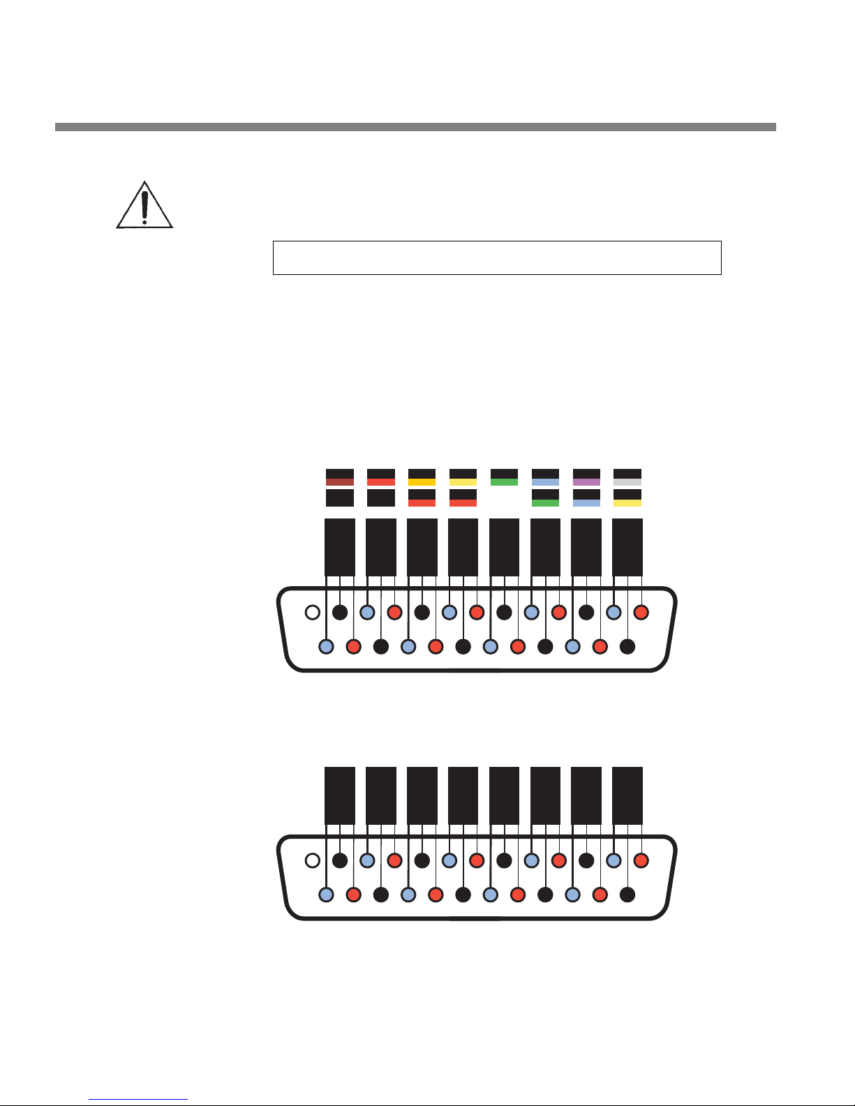
2-4
INSTALLATION ORBAN MODEL 1101
If you are upgrading from an earlier software version: If the ver-
sions of the driver, service, and application are incompatible, each
OPTIMOD-PC card will function in its default “sound card mode.” The
application will display the following message when you try to connect
to an incompatible card:
The OPTIMOD-PC driver version is incompatible with this application.
Please install latest driver and software.
If you get this error message, repeat the installation process by running
Setup from the Orban CD-R or as downloaded from ftp.orban.com/1101.
Do not uninstall the old version of OPTIMOD-PC before running the upgrade application. If you do so, you must reboot your computer before
running the Orban setup application.
4. Plan your installation.
Figure 2-1 on page 2-3 shows four possible installation scenarios:
A) OPTIMOD-PC cards are located on and are controlled from the local computer
TASCAM
ORBAN
BRN RED ORG YEL GRN BLU VIO GRY
BLK BLK RED RED GRN BLU YEL
A IN
A OUT
Left
Left
F- XLR
M- XLR
1 3 2
1 3 2
G +
G +
25 24 23 22 21 20 19 18 17 16 15 14
A IN
A OUT
Right
Right
F- XLR
M- XLR
1 3 2
1 3 2
G +
G +
REAR VIEW - MALE DB-25 CONNECTOR
Not
Used
D IN 2
Sync
F- XLR
1 3 2
G +
D IN 1
F- XLR
1 3 2
G +
D OUT
M- XLR
1 3 2
G +
12345678910111213
Figure 2-2: Wiring Diagram for the OPTIMOD-PC XLR Cable Assembly
A IN
Left
F- RCA
S S T
A OUT
Left
M- RCA
S S T
A IN
Right
F- RCA
S S T
A OUT
Right
M- RCA
S S T
Not
Used
D IN 2
Sync
F- RCA
S S T
D IN 1
F- RCA
S S T
D OUT
M- RCA
S S T
12345678910111213
Figure 2-3: Wiring Diagram for the OPTIMOD-PC RCA Cable Assembly
25 24 23 22 21 20 19 18 17 16 15 14
REAR VIEW - MALE DB-25 CONNECTOR
Page 57
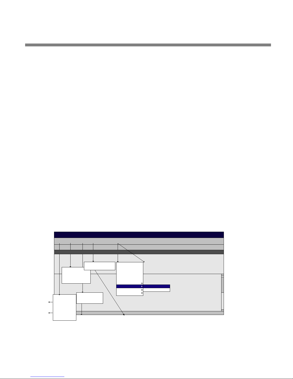
OPTIMOD-PC INSTALLATION
only.
B) OPTIMOD-PC cards are located elsewhere on the network, to be controlled by
a local computer that has no installed OPTIMOD-PC cards.
C) OPTIMOD-PC cards are located both locally and elsewhere on the network.
Local cards cannot be controlled from remote computers.
D) OPTIMOD-PC cards are located both locally and elsewhere on the network. All
cards are controllable from any machine on the network, whether local or
remote.
If your installation corresponds to scenario (A), skip to step 15 on page 2-
14. This scenario is typically true for simple, single-card installations such
as those where OPTIMOD-PC is used in a production studio.
5. Connect hardware inputs and outputs. (optional)
The wiring harness containing input and output cables is an optional accessory because some OPTIMOD-PC users will use only its software WAVE
inputs and outputs and do not need its hardware inputs and outputs.
2-5
Save Preset:
saves to a
selected
Windows folder
where you can
compare presets
Save Setup:
create multiple
Optimod PC
Mixers and save
them in a selected
Window's folder.
There are three versions of the cable assembly available: one terminated
with XLR connectors for balanced operation, one terminated with RCA
connectors for unbalanced operation, and one with bare wires. Figure 2-2
on page 2-4 shows how these cable assemblies are wired and can be used
as a guide for making your own harness.
Note that the diagram shows the rear view of the male connector that
terminates the cable assembly, not the front view. This is the same as the
front view of the female connector mounted on OPTIMOD-PC.
In the Orban XLR cable assembly, pin 2 of the XLR connectors is wired
EditFile
View Help
Tools Connect
Local:STREAM01 Active Preset: ROCK-MEDIUM
I/O Mixer
Basic Control
Advanced Control
__________________
I/O Mixer
Open Preset
Save Preset
Save Preset As...
________
Open Setup
Save Setup As
________
Exit
Administration
Toolbar
Status Bar
View Tool Tips
View: allows you to display or
hide the Toolbar, Status Bar,
and Tool Tips.
Add
Edit
Remov e
_________________
Disconnect
_________________
Local
New York
Los Angeles
London
Administration: allows you to rename cards and set both Administrator and User
Passwords when you are connected to a card at a Local or Remote site.
Connect: allows you to connect to different cards on your
local PC. You can also add card profiles, connect to cards,
and edit card profiles on PCs in remote locations.
Stream02
Stream02 Backup
TOOLBAR
METERS
CONTROLS
Controls appear when you select
Basic Control or Advanced Control
from Edit menu bar drop down options.
Figure 2-4: The Orban Control Application
Page 58
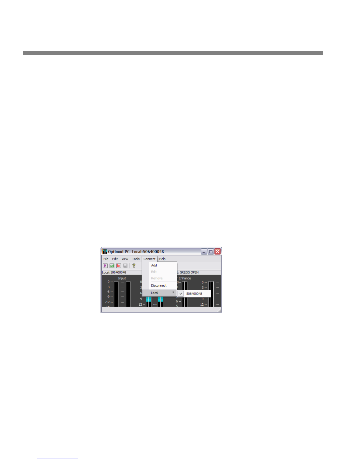
2-6
INSTALLATION ORBAN MODEL 1101
HIGH and pin 3 is wired LOW. Pin 1 is ground.
In the Orban RCA cable assembly, the center pin is HIGH, while the LOW
and SHIELD are wired together.
In the unterminated harness, the white and white/blue striped wires are
HIGH; the blue and blue/white striped wires are LOW. The shield is
ground.
Note that balanced cables wired to the Tascam® standard are also compatible with OPTIMOD-PC. Unbalanced cables may not work with all inputs and/or outputs. Figure 2-2 also shows the Tascam color codes.
6. Set up passwords and card names for cards in your computer. (optional)
A) Start the Optimod-PC control application,
(“agent”) in your computer’s system tray, or from Start > Programs > Orban >
Optimod-PC. (See Figure 2-4 on page 2-5.)
Newly installed cards have no passwords. You do not need to assign a
password to a card unless you want that card to be accessible to a network connected to your computer.
Once you have assigned passwords, these passwords can be changed either locally or on the network by anyone with the Administrator password for that card, but no one else. Do not lose the Administrator password you assign in the steps below.
B) Connect to the local card to which you are assigning a name and password.
C) From the Tools menu bar, choose “Administration.”
Optimod.exe, by clicking its icon
Initially, Optimod-PC software identifies a card by its serial number,
which it reads from the card. You can give the card an easily remembered
name (“alias”) by filling in the C
Optimod-PC software will then identify the card by this name from anywhere on the network.
ARD NAME field.
Page 59
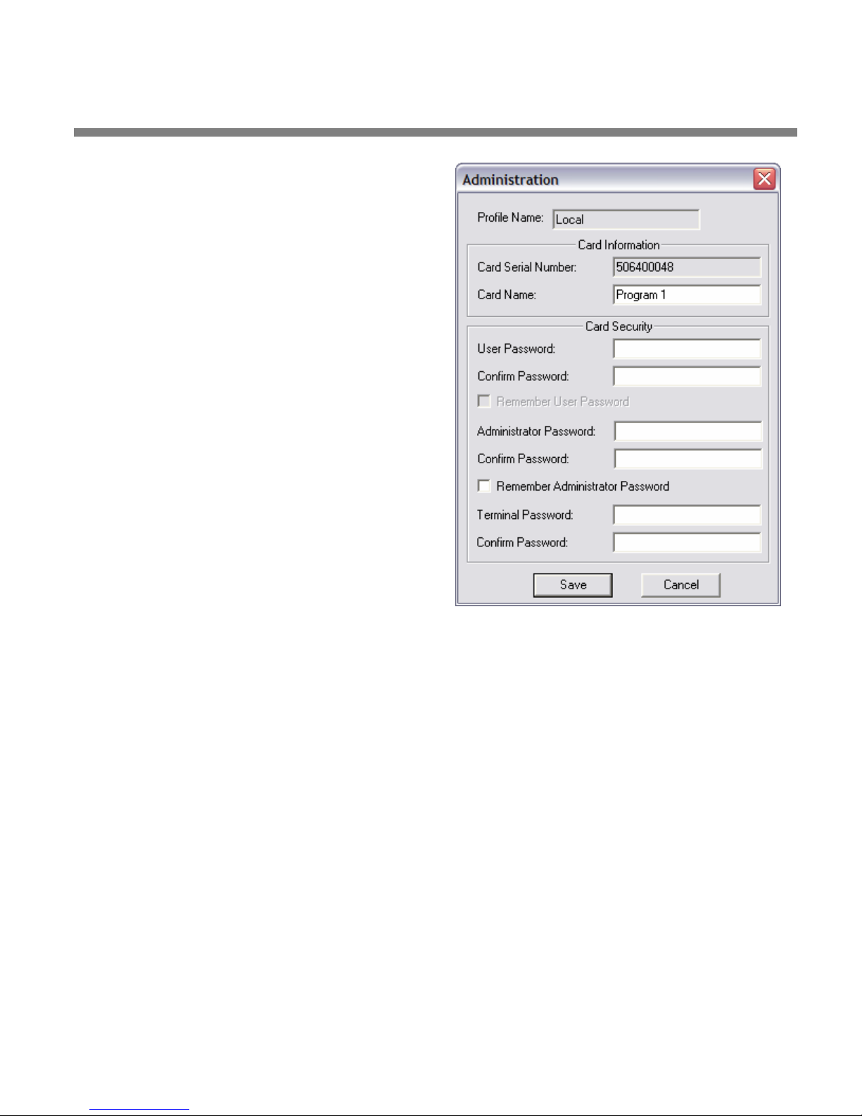
OPTIMOD-PC INSTALLATION
D) Assign a User Password to the card by filling
in the U
SER PASSWORD and CONFIRM
PASSWORD fields identically. This password
allows you to connect to a card via the
OPTIMOD-PC Control Application.
E) Assign a Terminal Password to the card by
filling in the T
ONFIRM PASSWORD fields identically. This
C
ERMINAL PASSWORD and
password allows you to connect to a card
via OPTIMOD-PC TCP/IP terminal server to
allow external control of the OPTIMOD-PC
cards from either a Telnet/SSH client or a
custom third party application. See
Optimod-PC System/Mixer Control API on
page 6-1.
If you do not assign a Terminal Password in
this step, your installation will not be secure
unless U
SE LOCALHOST ONLY FOR TERMINAL
ACCESS is checked (step (7.G) on page 2-9).
2-7
F) Assign an Administrator Password to the
card by filling in the A
DMINISTRATOR
PASSWORD and CONFIRM PASSWORD fields
identically.
Do not make the User and Administrator
passwords identical.
Figure 2-5: Card & Security Administration
Be sure to write down and remember the
Administrator Password because you must have it to change the card’s
User Password or the Card Name in the future. You may check R
EMEMBER
ADMIN. PASSWORD, but be aware that this will allow anyone with access to
your computer to change the User and Administrator passwords for this
card. If this privilege was used maliciously, it could lock you out of the
card, requiring an inconvenient editing of your computer’s Registry to
remove the unwanted password.
G) Click S
AVE to confirm your entries.
H) Repeat steps (B) through (G) for each new card installed in your local com-
puter.
When you re-enter the C
ONNECT menu, you will now see the cards listed by the
names you have assigned to them, not by their serial numbers.
7. Set up network access for all OPTIMOD-PCs on your computer. (optional)
If you want other computers to be able to access local cards via a TCP/IP network,
you must complete the following steps:
A) If the OPTIMOD-PC application is currently connected to a card, disconnect it
by choosing D
ISCONNECT from the CONNECT menu.
Page 60
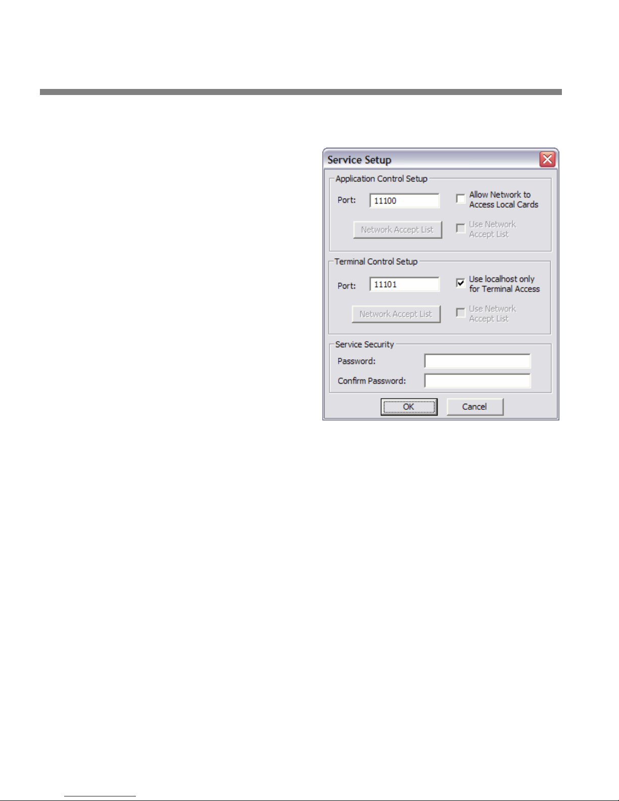
2-8
INSTALLATION ORBAN MODEL 1101
B) Navigate to
OOLS > SERVICE SETUP
T
C) Set the “Application Control
Setup” port through which
the OPTIMOD-PC Control
Application running on
networked computers can
access the OPTIMOD-PC
Service running on your local
computer.
The OPTIMOD-PC Service
allows you to access all
cards on a given computer through the same
port.
The default port is 11100.
If a given computer also
has OPTIMOD-PC 1100
cards installed, you must
assign the 1101 and 1100
cards different port
numbers to prevent
conflicts.
D) Set the “Terminal Control
Setup” port through which
the OPTIMOD-PC Control Application running on networked computers can
access the OPTIMOD-PC TCP/IP terminal server to allow external control of the
OPTIMOD-PC cards from either a Telnet/SSH client or a custom third party application. See Optimod-PC System/Mixer Control API on page 6-1.
The default port is 11101. If a given computer also has OPTIMOD-PC 1100
cards installed, you must assign the 1101 and 1100 cards different port
numbers to prevent conflicts.
E) Set ALLOW NETWORK TO ACCESS LOCAL CARDS as appropriate.
By default, this box is not checked. When it is not checked, no card in
your computer can be accessed through the OPTIMOD-PC Control Application running on the network.
Before you check this box, be sure that you have assigned a password to
each OPTIMOD-PC card in your computer (step 6 on page 2-6).
F) If you wish to allow only specified computers to access local cards via the
OPTIMOD-PC Control Application, check the Application Control Setup U
SE
NETWORK ACCEPT LIST.
The Network Accept List adds another layer of security beyond password
security. It is not strictly necessary to use this feature if you have assigned
passwords to all cards in your computer.
a) Click the NETWORK ACCEPT LIST button.
b) Click the A
DD button.
Page 61
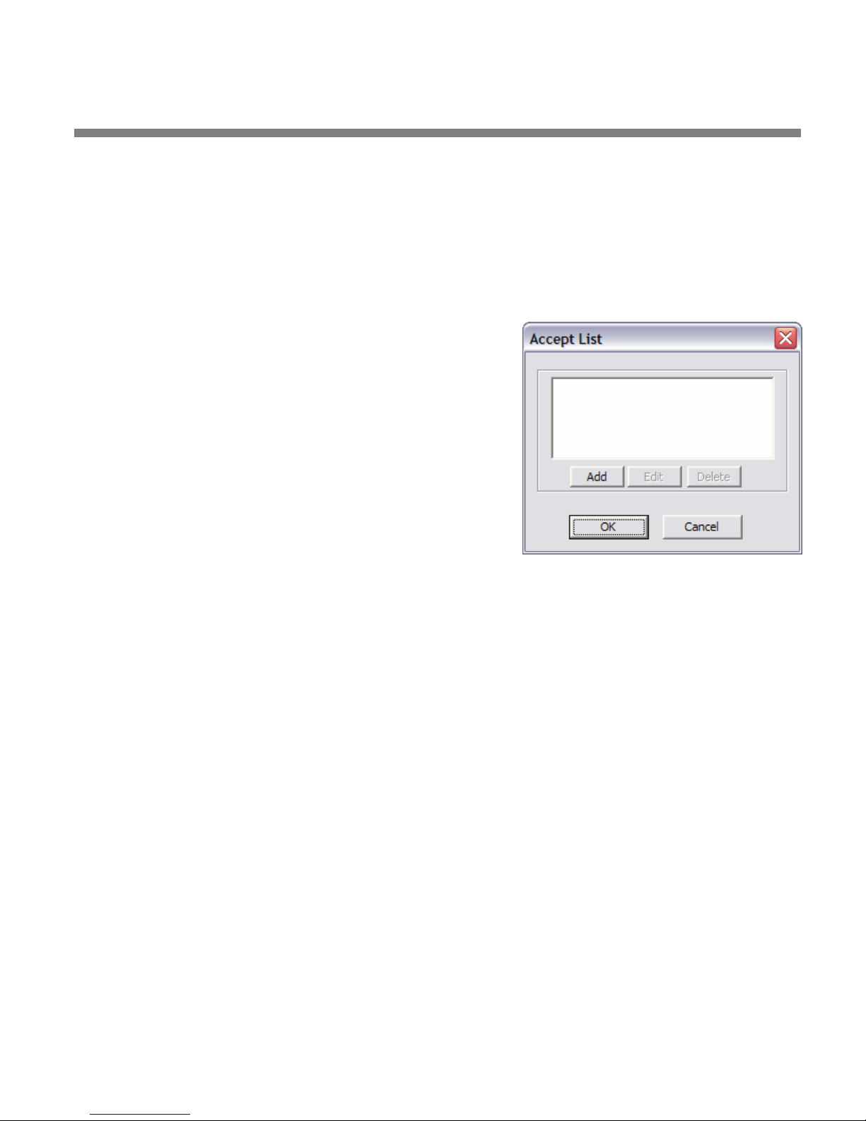
OPTIMOD-PC INSTALLATION
c) Enter host name, domain name, IP address, or subnet address in CIDR
format.
Examples:
host.domain.com Single Computer
domain.com Entire Domain
123.45.67.8 Single Computer
123.45.67.8/24 Entire IP (subnet) Range
123.45.67.8/255.255.255.0 Entire IP (subnet) Range
d) If you wish to add another computer, repeat steps
(a) through (c).
e) When you are finished adding computers, click OK.
2-9
G) Set U
SE LOCALHOST ONLY FOR TERMINAL ACCESS as
appropriate.
This box is checked by default. This prevents any
external computer on the network from connecting to
a local OPTIMOD-PC via the OPTIMOD-PC TCP/IP Terminal Server.
Before you uncheck this box, be sure that you have
assigned a password to each OPTIMOD-PC card in your
computer (step 6 on page 2-6).
H) If you wish to allow only specified computers to access local cards via the
OPTIMOD-PC TCP/IP Terminal Server, check the Terminal Control U
SE NETWORK
ACCEPT LIST.
The Network Accept List adds another layer of security beyond password
security. It is not strictly necessary to use this feature if you have assigned
passwords to all cards in your computer.
a) Click the NETWORK ACCEPT LIST button.
b) Click the A
DD button.
c) Enter host name, domain name, IP address, or subnet address in CIDR
format.
d) If you wish to add another computer, repeat steps (a) through (c).
e) When you are finished adding computers, click OK.
I) Create a Service Security Password.
Enter identical passwords in the S
SECURITY CONFIRM PASSWORD fields.
J) Click OK.
Your cards now have full security. Any OPTIMOD-PC control application on the
network will be unable to detect a card’s presence without knowing its User
Password in advance—the OPTIMOD-PC control application cannot automatically
poll the network to discover cards.
ERVICE SECURITY PASSWORD and SERVICE
Page 62
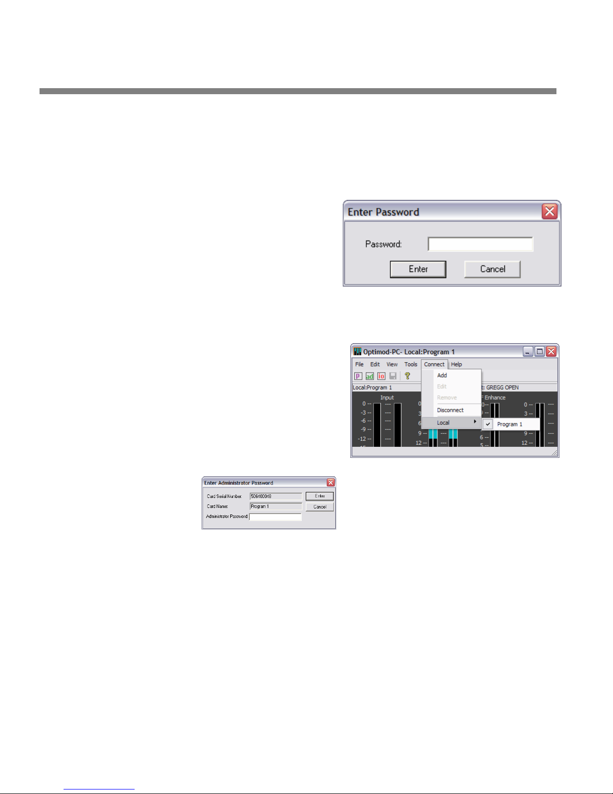
2-10
INSTALLATION ORBAN MODEL 1101
8. Edit the local OPTIMOD-PC server’s network accessibility, port numbers,
and Service Security Password. (optional)
A) If the OPTIMOD-PC application is currently connected to a card, disconnect it
by choosing D
B) Navigate to
OOLS > SERVICE SETUP.
T
C) Enter the Service Security Pass-
word that you originally set in
step (7.I) on page 2-9.
The Service Setup Window appears.
D) Edit parameters in this window as
desired. Then click OK. (See step 7 on page 2-7.)
9. Edit a given card’s name and/or passwords. (optional)
A) Connect to the local card to which
you are assigning a name and
password.
ISCONNECT from the CONNECT menu.
B) From the Tools menu bar, choose
“Administration.”
The Enter Administrator Password
window appears. Enter the card’s
Administrator password and hit En-
ter.
If you did not enter an Administrator Password in step (6.E), you will not
see the “Enter Administrator Password” dialog box and the Card and Security Administration window will appear immediately.
C) The Card and Security Administration window opens. Edit the fields as re-
quired. (See Figure 2-5 on page 2-7.)
D) Click “Save” to confirm your changes.
10. Add remote cards to your list of available cards. (optional)
To maintain security, all OPTIMOD-PC cards in the remote machines on your network are initially hidden from the Orban Control application on your computer.
You must explicitly “add” each card that you wish to control locally. To do so,
you must know three things: (1) the IP address of the remote computer in which
Page 63
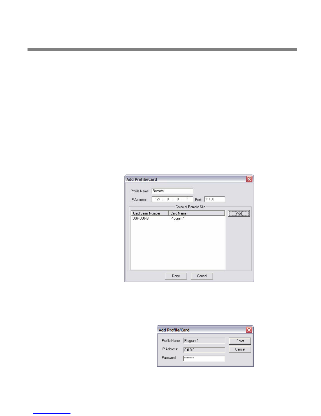
OPTIMOD-PC INSTALLATION
2-11
the card resides, (2) the port that was assigned to the Optimod Cards running on
the remote computer, and (3) the User or Administrator password of each card.
To add cards, you must be able to connect to the Orban server software on the
remote computer containing those cards. That is, the remote computer must be
on-line and connected to the network, and the Orban server software on that
computer must be running. If you are using a modem connection, this connection must already be established.
The Orban server software will be running if the remote computer is
turned on, you have installed your card and driver on that computer, the
OPTIMOD-PC Control software is installed on that computer, and the “Allow Network to Access Local Cards” box in S
page 2-8) is selected on a card in that system.
Orban server software does not have to be running on your local computer.
ERVICE SETUP (step 7.E) on
A) Add a remote computer to the list of available computers containing
OPTIMOD-PC cards:
a) Select C
ONNECT/ADD.
The ADD PROFILE /
CARDS(S) menu appears.
b) Enter the Profile Name,
IP Address, and Port of
the remote computer
The Profile Name can
be any name you wish
to use—for example,
“Boston.” The profile
name is known only to
your local computer.
The network identifies
a given computer by its
IP address and port,
not its profile name.
The profile name is merely a convenient alias that you use to help identify a remote computer hosting OPTIMOD-PC cards without your having
to memorize the computer’s IP address.
B) Add the remote computer’s cards to the list of cards that you can access:
You must have the User Passwords of all cards you wish to add.
a) Click ADD.
The ADD PROFILE/CARD dialog box
opens.
b) Enter the card’s User Password into
ASSWORD field.
the P
c) Click ENTER to confirm your entry.
Page 64
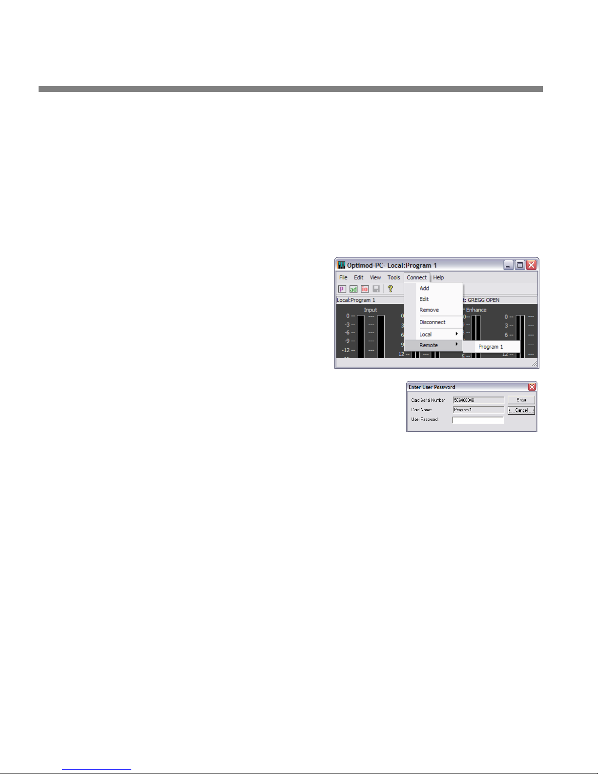
2-12
INSTALLATION ORBAN MODEL 1101
The newly added card(s) will appear in the list of “Cards at Remote Site.”
d) Repeat steps (a) through (c) for each card in the remote computer.
C) Click D
D) Add remote computer Profiles and the cards in each Profiled computers as de-
sired, by repeating steps (A) through (C) for each remote computer.
11. Connect to a remote card. (optional)
You can now connect to any card that you added in step 8 on page 2-10 if this
card’s server is running and connected to the network.
A) Click the C
down menu appears containing a
list of all remote computers. Drag
your mouse down to the desired
computer to reveal a submenu
containing all cards within it that
have been added. Select the de-
sired card to connect to it.
B) The “Enter User Password” dialog
box appears. Enter the password
and click E
box automatically in the future, check the
R
SECURITY ADMIN screen on your local computer.
(Only Administrators of your local Machine can
restore this dialog box once you have specified that it is to be bypassed.)
ONE when you have added all cards in a given remote computer.
ONNECT menu. A drop-
NTER. If you wish to bypass this dialog
EMEMBER USER PASSWORD box in the CARDS AND
After you click E
card to which you just connected, and you can recall presets, adjust in-
put/output levels, edit and save presets, etc.
12. Change passwords and card names over a network. (optional)
If you have the Administrator password for a card, you can change the card’s
Name, User Password, and Administrator Password from anywhere on the network. This can be particularly useful if you are in a large broadcast group that
has one administrator for audio processing throughout the group’s stations.
To administer a card, Orban server software must be running on the computer in
which the card is installed and that computer must be connected to the network.
A) Select T
The “Enter Administrator Password” dialog box appears.
B) Enter the administrator password for that card and click E
The “Card and Security Administration” dialog box appears. (See Figure
2-5 on page 2-7.)
OOLS > ADMINISTRATION
NTER, the Control application will display the state of the
NTER.
Page 65
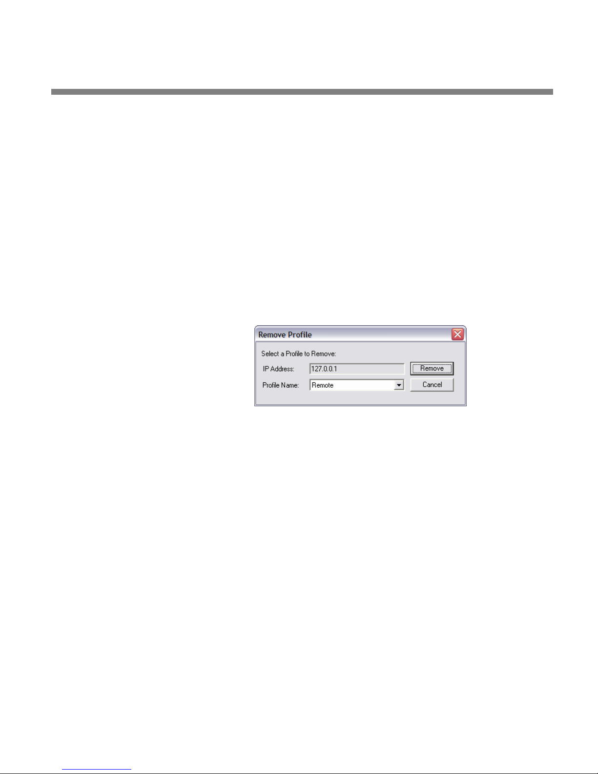
OPTIMOD-PC INSTALLATION
2-13
You can enter a new User Password, Administrator Password, and/or Card
Name in the appropriately named fields in the dialog box. If you do not
explicitly change the value in a field, it will remain unchanged.
We do not recommend checking REMEMBER ADMINISTRATOR PASSWORD because this action introduces considerable security risk.
C) Click SAVE to confirm your changes.
13. Delete a remote computer’s profile. (optional)
If you no longer wish to have a particular remote computer appear in the
list of available computers, you can delete it from the list.
A) Select C
ONNECT/REMOVE.
B) Specify the remote computer you wish to remove by selecting its name in the
drop-down P
C) Click R
EMOVE
ROFILE NAME list.
The remote computer’s profile
(and the profiles of all of its
corresponding cards) is removed from your local computer. This action does not affect any other computer on the
network.
You can restore the remote computer’s profile by following the instructions in step (10.A) on page 2-10. If you do so, you will also have to readd all of the cards in the host computer to the client computer by executing step (10.B).
14. Defeat the OPTIMOD-PC service in a computer that does not contain
OPTIMOD-PC cards. (optional)
If a computer running the OPTIMOD-PC control application contains no
OPTIMOD-PC cards, you may wish to defeat the OPTIMOD-PC service on that
computer (although this is not required).
This scenario applies to computers that control OPTIMOD-PC cards on a
network, yet contain no local cards.
A) On the computer, navigate to
TART > SETTINGS > CONTROL PANEL > ADMINISTRATIVE TOOLS > SERVICES.
S
B) Locate
C) Right-click
D) In the S
OptimodPcService in the list of services. Right-click it and select STOP.
OptimodPcService and select PROPERTIES.
TARTUP TYPE drop-down list, select DISABLED or MANUAL. (Either will de-
feat the service.)
If you wish to reactivate the service in the future, reset the STARTUP TYPE
UTOMATIC. Then right-click OptimodPcService and select START.
to A
Page 66
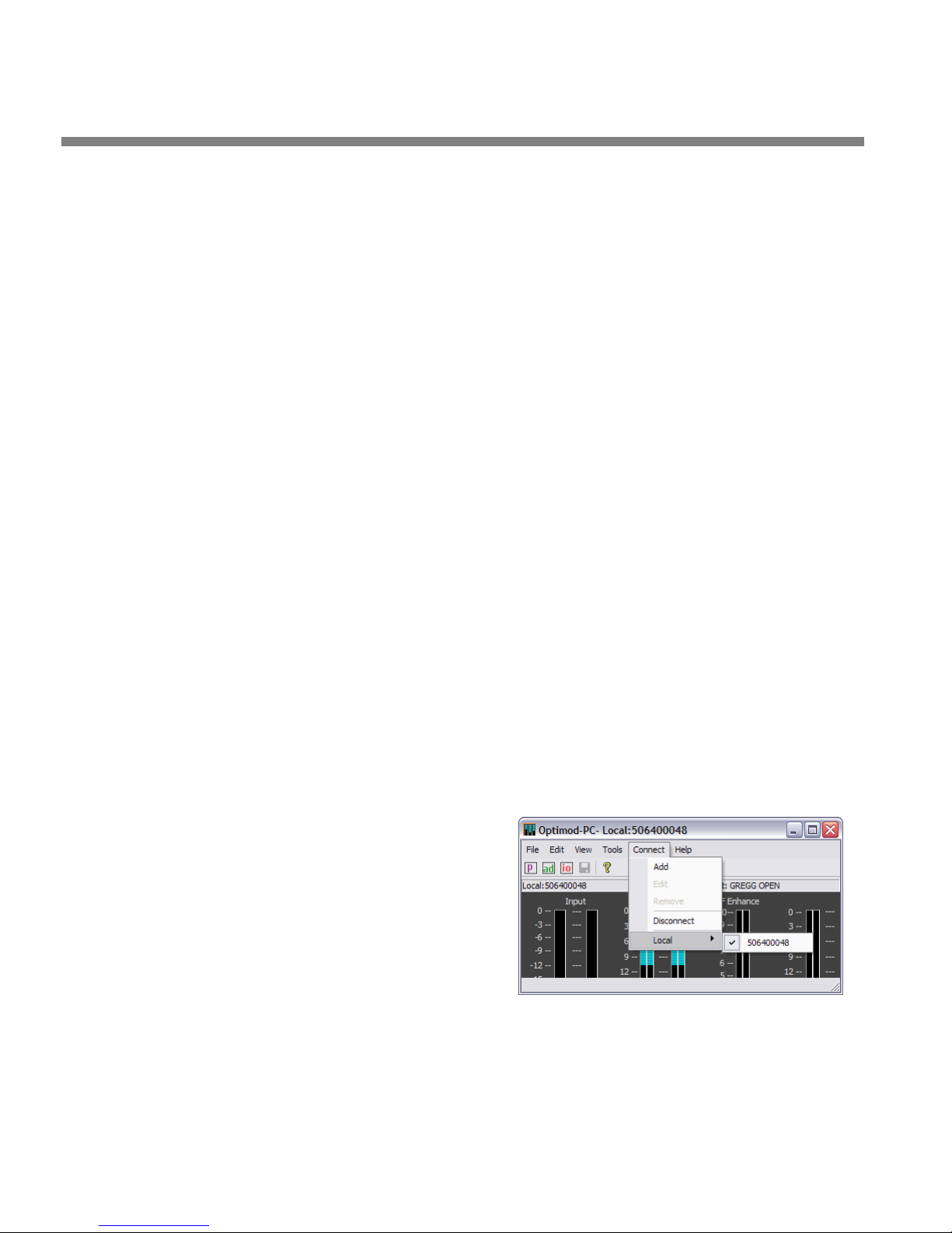
2-14
INSTALLATION ORBAN MODEL 1101
15. Simple installations: Connecting to an OPTIMOD-PC card.
In the simplest possible installation (one card being controlled locally in one
computer), the OPTIMOD-PC control application,
Optimod.exe, will automatically
connect to (and control) the card when you start the software by clicking its
“agent” icon (in the right-hand side of the Windows taskbar).
The installer will ordinarily place a shortcut to the OPTIMOD-PC control
application in your computer’s START menu under
(“PC2” indicates that the software is for a model 1101 card, not an 1100
card). If you so specified during installation, there will also be an icon for
OptimodPC2.exe on your desktop and a small icon (agent) in your system
tray. When you click on the agent icon, it will open the OPTIMOD-PC
control application and automatically connect to your card. On the other
hand, if you start the software from the START menu or from a desktop
icon, it will not automatically connect to your card; you must do this
manually from the OPTIMOD-PC control application’s C
The installer will also install the “Orban OPTIMOD-PC 1101” Windows
Service application and set it to start automatically at boot-up. Please
note that the network cannot see your OPTIMOD-PC card(s) unless you
explicitly expose them to the network as described in step 7 on page 2-7.
Auto-starting the Service at boot time allows it to automatically reload
OPTIMOD-PC’s DSP code on boot, which can be invaluable in a streaming
application where the stream must automatically restart after a system
crash. The server application has no user controls and you do not have to
interact with it or otherwise worry about it other than to be aware that
it is normal for it be running in the background as a Windows service.
Orban/OPTIMOD-PC2.
ONNECT menu.
If you have more than one card installed in your computer, you must select the
one you are controlling by choosing it from a list available from the C
menu. If you did not edit the names of the cards, then the list will show the
cards’ serial numbers.
If, for convenience in identifying them, you wish to assign them easily remembered names (“aliases”), you must edit their profiles as described in step 6 on
page 2-6.
To connect to a card (thereby controlling it), left-click
drag the mouse to
CONNECT and
LOCAL. Continue
to drag the mouse to the desired
card name that appears in the
submenu, and release the mouse
button.
16. Connect inputs and outputs. (optional)
This is not required if you are going to be using only WAVE inputs and outputs,
which are routed through your computer’s operating system. In this case, skip to
Setting up OPTIMOD-PC: the Orban Control Application on page 2-18.
ONNECT
Page 67

OPTIMOD-PC INSTALLATION
If you are using hardware inputs or outputs, see the hookup and grounding information on the following pages.
Audio Input and Audio Output Connections..................................Page 2-15
AES3 Digital Input and Output ........................................................Page 2-16
Grounding .........................................................................................Page 2-16
2-15
Audio Input and Output Connections
Cable
We recommend using two-conductor foil-shielded cable (such as Belden
8451/1503A/1504A/1508A or equivalent for analog signals and Belden 1800B/1801B
or equivalent for digital signals), because signal current flows through the two conductors only. The shield does not carry signal, and is used only for shielding.
Connectors
The cable assemblies are optional and must be purchased separately from
OPTIMOD-PC. If you order the model 1101/CBLXLR assembly, input and output connectors are XLR. If you order OPTIMOD-PC/CBLRCA assembly, input and output connectors are RCA. If you order OPTIMOD-PC/CBL assembly, the cables are terminated
in bare wires so you can terminate them with the connectors of your choice.
In the XLR-type connectors, pin 1 is CHASSIS GROUND, while pin 2 and
pin 3 are a balanced, floating pair. This wiring scheme is compatible with
any studio-wiring standard: If one pin is considered LOW, the other pin is
automatically HIGH. However, we arbitrarily call pin 2 HIGH and pin 3
LOW to conform to AES standards.
In the RCA-type connectors, the center pin (called “T” [for “tip”] in the
diagram) is HIGH, while the outer sleeve (called “S” in the diagram) is
LOW and SHIELD.
See Figure 2-2: Wiring Diagram for the OPTIMOD-PC XLR and Figure 2-3:
Wiring Diagram for the OPTIMOD-PC RCA Cable Assembly on page 2-4.
Analog Audio Input
Using Orban’s mixer application (available from the TOOLS menu on the Orban Control application or from your computer’s control panel in Multimedia), you can
choose a nominal input level of either –10dBV (IHF consumer level) or +4dBu (professional level).
(0dBu = 0.775Vrms. For this application, the dBm@600Ω scale on voltmeters can be read as if it were calibrated in dBu. 0dBV = 1.0Vrms.)
The peak input level that causes overload depends on whether you have set the input for –10 dBV (–7.8 dBu) or +4dBu. Overload occurs at approximately +9.2 dBV
(+11.4 dBu) for the –10 dBV setting and +20 dBu for the +4 dBu setting.
Page 68

2-16
INSTALLATION ORBAN MODEL 1101
The electronically balanced input uses an ultra low noise and distortion differential
amplifier for best common mode rejection. It is compatible with most professional
and semi-professional audio equipment, balanced or unbalanced, having a source
impedance of 600Ω or less. The input is EMI suppressed.
• Input connections are the same whether the driving source is balanced or unbal-
anced.
• Connect the red (or white) wire to the pin on the XLR-type connector (#2 or #3)
that is considered HIGH by the standards of your organization. Connect the
black wire to the pin on the XLR-type connector (#3 or #2) that is considered
LOW by the standards of your organization.
• In low RF fields (like a studio site not co-located with an RF transmitter), connect
the cable shield at OPTIMOD-PC input only—it should not be connected at the
source end. In high RF fields (like a transmitter site), also connect the shield to
pin 1 of the male XLR-type connector at the source driving OPTIMOD-PC.
• If the output of the driving unit is unbalanced and does not have separate
CHASSIS GROUND and (–) (or LOW) output terminals, connect both the shield
and the black wire to the common (–) or ground terminal of the driving unit.
Analog Audio Monitor Output
Electronically balanced and floating outputs simulate a true transformer output. The
source impedance is 50Ω. The output is capable of driving loads of 600Ω or higher.
The peak output level is adjustable up to +20dBu before clipping occurs. The outputs are EMI suppressed.
• If an unbalanced output is required (to drive unbalanced inputs of other equip-
ment), it should be taken between pin 2 and pin 3 of the XLR-type connector.
Connect the LOW pin of the XLR-type connector (#3 or #2, depending on your
organization’s standards) to circuit ground, and take the HIGH output from the
remaining pin. No special precautions are required even though one side of the
output is grounded.
• Use two-conductor foil-shielded cable (Belden 8451, or equivalent).
• At OPTIMOD-PC’s output (and at the output of other equipment in the system),
do not connect the cable’s shield to the CHASSIS GROUND terminal (pin 1) on
the XLR-type connector. Instead, connect the shield to the input destination.
Connect the red (or white) wire to the pin on the XLR-type connector (#2 or #3)
that is considered HIGH by the standards of your organization. Connect the
black wire to the pin on the XLR-type connector (#3 or #2) that is considered
LOW by the standards of your organization.
AES3 Digital Input and Output
There are two AES3 inputs and two AES3 outputs. With v1.0 software, the two outputs emit the same signal. Both inputs accept program audio and can be mixed; either input can also accept AES11 house sync. The program inputs and output are
both equipped with sample rate converters. The output can operate at 32, 44.1, 48,
Page 69

OPTIMOD-PC INSTALLATION
2-17
88.1, and 96 kHz. The inputs can receive sample rates between 30 and 96 kHz; two
asynchronous digital inputs can therefore be mixed.
Per the AES3 standard, each digital input or output line carries both the
left and right stereo channels. The connection is 110Ω balanced. The
AES3 standard specifies a maximum cable length of 100 meters. While
almost any balanced, shielded cable will work for relatively short runs (5
meters or less), longer runs require use of 110Ω balanced cable like
Belden 1800B, 1801B (plenum rated), multi-pair 180xF, 185xF, or 78xxA.
Single-pair category 5, 5e, and 6 Ethernet cable will also work well if you
do not require shielding. (In most cases, the tight balance of Category
5/5e/6 cable makes shielding unnecessary.)
The AES3id standard is best for very long cable runs (up to 1000 meters).
This specifies 75Ω unbalanced coaxial cable, terminated in BNC connectors. A 110Ω/75Ω balun transformer is required to interface an AES3id
connection to your Optimod’s digital input or output.
The digital input clip level depends on the setting on the DIGITAL 1 INPUT
IGITAL 2 INPUT mixer controls. To avoid clipping, set these so that the
and D
ROCESSOR MIXER OUTPUT meters never indicate red.
P
A Backup function allows inputs to be programmed to automatically
mute unless digital lock is lost on another input. Such loss of lock causes
the backup input to be unmuted. You can arrange this function so that,
for example, loss of lock on digital input 1 causes digital input 2 to unmute, and loss of lock on both digital inputs causes the analog input to
unmute. This allows you to connect backup program sources to ordinarily
unused inputs and have the backup inputs activate automatically if the
primary program feed is lost.
Note that OPTIMOD-PC does not fully implement the AES11 standard because it also does not pass AES3 user bits and does not control the phasing of the AES data frames between reference and output. However, it
correctly locks the sample frequency of the output to the sample frequency of the reference.
Grounding
Very often, grounding is approached in a “hit or miss” manner. However, with care
it is possible to wire an audio studio so that it provides maximum protection from
power faults and is free from ground loops (which induce hum and can cause oscillation).
In an ideal system:
• All units in the system should have balanced inputs. In a modern system with
low output impedances and high input impedances, a balanced input will
provide common-mode rejection and prevent ground loops—regardless of
whether it is driven from a balanced or unbalanced source.
OPTIMOD-PC has balanced inputs.
• All equipment circuit grounds must be connected to each other; all equipment
chassis grounds must be connected together.
Page 70

2-18
INSTALLATION ORBAN MODEL 1101
• In a low RF field, cable shields should be connected at one end only—
preferably the destination (input) end.
• In a high RF field, audio cable shields should be connected to a solid earth
ground at both ends to achieve best shielding against RFI.
• Whenever coaxial cable is used, shields are automatically grounded at both
ends through the terminating BNC or phono connectors.
Power Ground
Ground the computer chassis through the third wire in the power cord. Proper
grounding techniques never leave equipment chassis unconnected to power/earth
ground. A proper power ground is essential to safe operation. Lifting a chassis from
power ground creates a potential safety hazard.
Audio ground loop or hum problems are often solved by proper shield connections
and/or by making sure that analog inputs and outputs are correctly balanced. They
should never be solved by disconnecting or lifting power grounds. Refer to the previous section, Grounding, for details.
Setup: The OPTIMOD-PC Control Application
Once you have connected the Orban Control application to an OPTIMOD-PC card,
the software allows you to control the card as if it were a dedicated hardware processor like an Orban OPTIMOD. The Control application displays gain reduction meters, as well as controls that allow you to edit the sound of the factory presets to
your liking. Section 3 of this manual explains these sound editing controls in detail.
This section of the manual tells you how to set up the input and output controls of
an OPTIMOD-PC card, with emphasis on connections that use OPTIMOD-PC’s external analog or digital inputs and outputs to emulate a hardware audio processor.
Starting on page 2-33, we provide additional instructions for users who want to connect OPTIMOD-PC’s inputs and outputs to other programs (like streaming encoders)
through the Windows WAVE multimedia mechanism inside your computer. Even if
you are only using OPTIMOD-PC’s WAVE input and output, you should still work
through all of the instructions below, ignoring those that apply only to OPTIMODPC’s hardware I/O.
1. From the Tools
The I/O Mixer is a tabbed control panel that allows you to configure many global
OPTIMOD-PC parameters, like input and output levels. If you are familiar with
Orban’s hardware processors (like our Optimod-PC 6200/6200S), you will recognize many functions as being similar to those found in OPTIMOD-PC’s S
SETUP menu. However, the OPTIMOD-PC I/O Mixer is more powerful.
menu, bring up the I/O Mixer.
YSTEM
Page 71
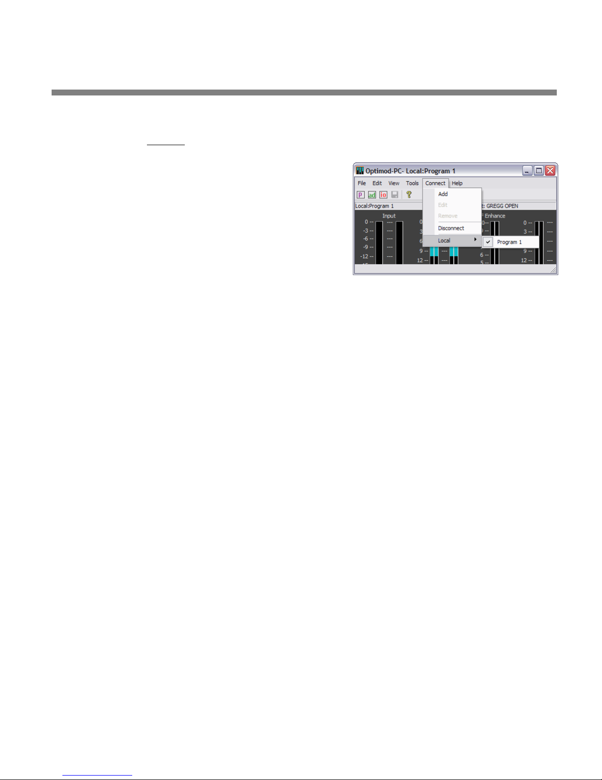
OPTIMOD-PC INSTALLATION
2-19
2. Select the card you are setting up.
A) From the Connect
menu on the Control application, select the card you are
setting up by connecting to it.
If you have only one card installed in your machine
and you open the OPTIMOD-PC application from the
agent, you do not need to connect manually
because you will automatically be connected to this
card already.
If you wish, you can edit the factory default
Input/Output (“IO”) setup. You also have the option
PEN SETUP or SAVE SETUP AS in the Control
to O
application’s F
ILE menu. Therefore:
• You can save your current setup to a file and then apply it to another card.
• You can load a previously saved setup into the card that is currently se-
lected.
B) To copy an IO setup from a source card to a destination card (optional):
a) If you have not already saved the IO setup you wish to apply to the
destination card, use the Orban Control application to connect to the
source card. Then go to FILE/SAVE SETUP and save the IO setup of the source
card.
When saving, use any legal operating system filename other than de-
fault.orbfs
A given card’s setup is stored in the Registry on the computer where that
card resides.
The current active setup file is always the last file that was recalled by the
ILE/OPEN SETUP operation. If you have never recalled a setup file this
F
way, the current active setup is stored in a file named system.orbs.
The current active setup file is a transient file. That is, the Orban Control
application updates it whenever you change the setup manually. The
Orban Control application also automatically updates the file when the
application starts and reads the setup information from the Registry. You
cannot assume that a *.orbs setup file (other than
static or that it will retain its original information.
The factory default system setup is stored as
read-only file. It is the only system setup file that is static and unchanging. For further security, it is automatically regenerated each time the
Orban Control Program or Service starts up.
, which is a reserved name. Setup files have the form *.orbs.
default.orbfs)is
default.orbfs. This is a
b) Connect the Orban Control application to the destination card.
c) Go to F
ILE/OPEN SETUP.
d) Navigate to the folder containing the setup file you wish to retrieve.
This will usually be the file you saved in step (a).
Page 72

2-20
INSTALLATION ORBAN MODEL 1101
The OPTIMOD-PC file system labels the card folders by their serial numbers. Look for the folder labeled with the source card’s serial number. In
that folder will be a preset folder containing the setup you wish to restore.
e) Highlight the setup file and select OPEN.
The Orban Control application will automatically make a copy of justopened setup file in the destination card’s Presets folder. It will automatically update this file if you make manual changes to the destination
card’s IO setup. The original setup file is not changed.
C) If you wish to edit an existing (or factory) setup, proceed to step 3 below.
D) When you are finished setting up each card, close the
clicking D
ONE.
I/O MIXER window by
3. Configure global audio processing parameters.
A) From the T
OOLS menu, open the I/O Mixer and click the Configuration tab
The Configuration page appears:
B) Set the M
AX LOWPASS FILTER cutoff frequency.
[10.0 kHz] to [20.0 kHz]
You can set OPTIMOD-PC’s audio bandwidth in two places:
(1) in the I/O Mixer’s C
tab. (If the EQ
tab is not visible, click the AD button on the toolbar.)
ONFIGURATION tab, and (2) in the main window’s EQ
OPTIMOD-PC’s bandwidth is always the lowest of these settings. The fre-
quency in C
ONFIGURATION is a technical parameter that determines the
highest bandwidth available. The installing engineer should set it to be
appropriate for the sample rate of the digital system that OPTIMOD-PC is
driving. For example, if OPTIMOD-PC is driving a system with a 32 kHz
sample rate, set the M
AX LOWPASS FILTER cutoff frequency to 15.0 kHz.
That way, a setting of 20 kHz in the EQ tab will not cause excessive
bandwidth and aliasing because OPTIMOD-PC will automatically override
it with the M
AX LOWPASS FILTER cutoff frequency setting.
Note that the LP filter on the EQ tab is part of the active preset, like any
other equalization control in the preset. If you recall a different preset,
the L
determine the system bandwidth (unless, of course, the L
cutoff frequency setting in the new preset is higher than the MAX
LOWPASS FILTER cutoff frequency parameter in the CONFIGURATION page).
C) Set the AGC mode as appropriate for your installation.
[Enabled] or [Disabled]
This control turns OPTIMOD-PC’s internal AGC (Automatic Gain Control)
on [enabled] or off [disabled].
In radio applications, it is common to have an external AGC at the studio
side of a studio-to-transmitter link to protect the link from overload.
Most of the processing structures in OPTIMOD-PC control level with a
OWPASS FILTER cutoff frequency control in the new preset will now
OWPASS FILTER
Page 73
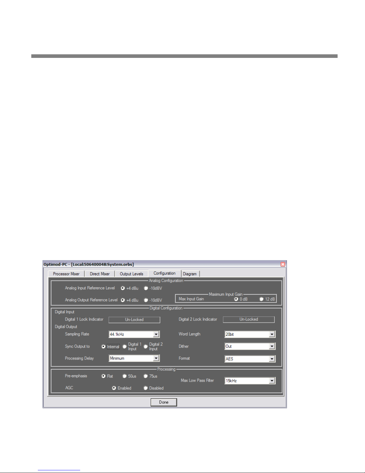
OPTIMOD-PC INSTALLATION
2-21
preliminary AGC internal to OPTIMOD-PC. If you are using an external
AGC device (such as an Orban 6300 multipurpose audio processor or another OPTIMOD-PC) in front of OPTIMOD-PC, set OPTIMOD-PC’s internal
AGC to D
not “fight” each other and that they do not simultaneously increase gain
(resulting in increased noise).
If you are using an Orban 4000 Transmission Limiter, set the AGC to
NABLED (so that the AGC function in OPTIMOD-PC continues to work).
E
The Orban 4000 is a transmission system overload protection device; it is
normally operated below threshold. It is not designed to perform an AGC
or gain-riding function and it cannot substitute for the AGC function in
OPTIMOD-PC.
ISABLED. This is to ensure that the internal and external AGCs do
Temporarily set AGC to ENABLED so that the Analog and Digital Input ref-
erence level alignment steps (below) will work correctly. After you have
finished with these steps, set the AGC
parameter appropriately for your
installation.
D) Set the Processing Delay.
[Minimum], [30 fps], [29.97 fps], [25 fps], [24 fps], [24-57 ms]
OPTIMOD-PC can add time delay to make its input/output delay exactly
one frame, using a variety of different standards. The selections are
INIMUM (depends on software version; typically between 14 and 24 ms),
M
24 milliseconds, 30 fps, 29.97 fps (NTSC color video), 25 fps (most PAL
video), and 24 fps (film).
You can also choose delay in one-millisecond intervals from 24 to 60 milli-
Figure 2-6: Configuration Page in the I/O Mixer
Page 74

2-22
INSTALLATION ORBAN MODEL 1101
seconds by choosing the desired value from the bottom entries in the
drop-down list.
4. Set digital output properties. (optional)
[Skip to “Input Setup” on page 2-24 if you will not be using OPTIMOD-PC’s
WAVE output or AES3 digital output.]
There are several properties you can set to match OPTIMOD-PC’s AES3 digital
outputs to your requirements.
A) Set the AES3 Digital Output sample rate.
[32], [44.1], [48 kHz], [88.2 kHz] or [96 kHz]
48 kHz or 96 kHz are preferred because their samples are synchronous
with the peak-controlled samples in the processing.
Selecting a 32 kHz output sample rate will automatically set the highest
available audio bandwidth to 15 kHz.
B) Set the Digital Output Sync mode to internal or external.
[Internal], [Digital 1 Input], or [Digital 2 Input]
OPTIMOD-PC’s AES3 output has a hardware sample rate converter that
allows the output sample rate to be synchronized to a source.
• The I
• The E
If a valid AES3 signal is present at the designated sync input, it will be
used for synchronization. If lock is unavailable, OPTIMOD-PC automati-
cally switches to I
sync after one second of continuously valid AES3 signal lock at a valid
sample rate. Furthermore, external lock is only permitted when the out-
put rate matches the sync (or AES3 input) rate.
C) Set the desired output word length.
[14 bits], [16bits], [18bits], [20bits], and [24bits]
The largest valid word length in OPTIMOD-PC is 24 bits. OPTIMOD-PC can
also truncate its output word length to 20, 18, 16, or 14 bits. If the input
material is insufficiently dithered for these lower word lengths,
OPTIMOD-PC can add dither (see the next step), which is wise if the input
material is insufficiently dithered for these lower word lengths.
NTERNAL sync setting synchronizes the output words at the AES3 out-
put to OPTIMOD-PC’s internal clock.
XTERNAL setting synchronizes the output rate to the input rate. You
can use either the D
The same input can also supply audio. If a given input is used only as a sync
source, it is wise to check the M
and Direct Mixer.
IGITAL 1 INPUT or the DIGITAL 2 INPUT as the sync source.
UTE box for that input in the Processor mixer
NTERNAL. OPTIMOD-PC automatically returns to external
D) Adjust DITHER to on or off, as desired.
[in] or [out]
Page 75

OPTIMOD-PC INSTALLATION
2-23
OPTIMOD-PC can add “high-pass” dither before any truncation of the
output word. The amount of dither automatically tracks the setting of
ORD LENGTH control.
the W
OPTIMOD-PC’s dither is first-order noise shaped dither that adds less
noise in the midrange than white PDF dither. However, unlike extreme
noise shaping, it adds a maximum of 3dB of excess total noise power
when compared to white PDF dither. It is therefore a good compromise
between white PDF dither and extreme noise shaping.
In many cases, you will not need to add dither because the source material has already been correctly dithered. However, particularly if you use
the Noise Reduction feature, the processing can sometimes attenuate input dither so that it is insufficient to dither the output correctly. In this
case, you should add dither within OPTIMOD-PC.
E) Set digital output format.
[AES3], [SPDIF]
This control determines whether the status bits supplied at the digital
output are in Professional (AES3) or Consumer (SPDIF) mode.
It does not affect the output level or source impedance, both of which
correspond to the AES3 standard.
5. Set preemphasis curve on which the look-ahead limiting operates.
[Flat], [50 µs], [75 µs]
Normally, OPTIMOD-PC will feed transmission channels that do not use
preemphasis and you should set this control F
LAT. Rarely, the transmission
channel uses preemphasis. (An example is an analog microwave studiotransmitter link in broadcast applications.) For these applications, you can
apply preemphasis before OPTIMOD-PC’s look-ahead limiter so it will
control the peaks of the preemphasized audio. A deemphasis filter after
the look-ahead limiter then restores “flat” audio at OPTIMOD-PC’s output; it is assumed that the transmitter driven by OPTIMOD-PC will restore
the preemphasis before the signal is transmitted.
When in doubt, choose F
Unlike OPTIMOD-FM and OPTIMOD-TV, OPTIMOD-PC cannot emit the
preemphasized signal, which would allow the transmitter’s preemphasis
filter to be bypassed. Instead, you must always use the transmitter’s builtin preemphasis filter.
Because its processing is configured to be most effective with “flat media,” OPTIMOD-PC cannot provide extreme loudness for preemphasized
radio channels. Use one of Orban’s Optimod-FM processors for this application. For analog television with FM aural carrier(s), use Optimod-TV
8382.
When operated with preemphasis, the look-ahead limiter should only be
used for light protection limiting with a low duty cycle. Otherwise, you
may hear pumping on material with a lot of high frequency energy like
LAT operation.
Page 76
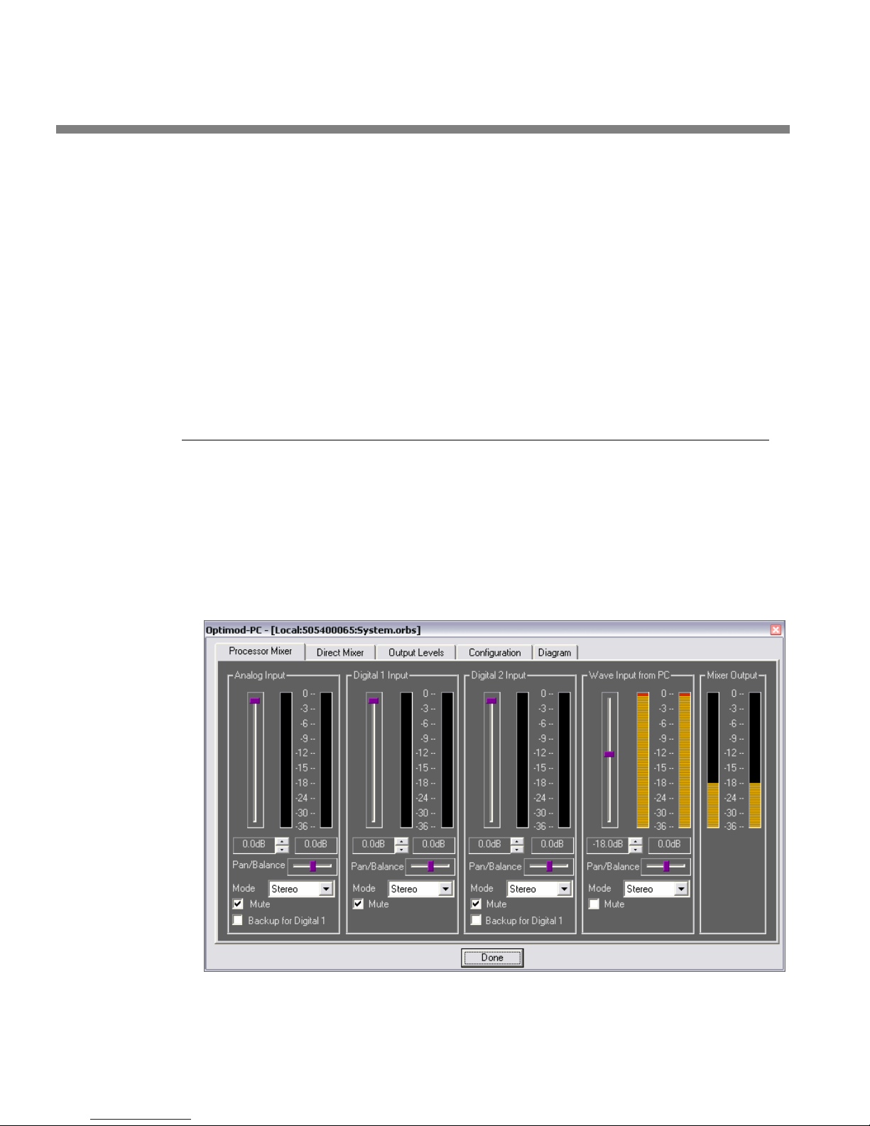
2-24
INSTALLATION ORBAN MODEL 1101
sibilance and cymbals. The cure is lowering the LIMITER DRIVE control until the problem is no longer audible.
If you find that lowering the
loss, you can use the Band 5 compressor as a high frequency limiter to
compromise between loudness and limiting artifacts. Set B5
RELEASE to +6 and B5 STEREO COUPLING to OFF. Adjust B5 THRESHOLD control until you see gain reduction on the Band 5 GR meter with problematic material. Continue to lower the B5
longer hear gain pumping. Instead, you will probably hear some high
frequency loss. This loss is less subjectively objectionable than gain pumping.
You can use the AGC+LIMITER
do this. See AGC+[FLAT, 50 µs, 75 µs] LIMITER on page 3-18.
LIMITER Drive causes too much loudness
DELTA
THRESHOLD control until you no
factory presets as an example of how to
Input Setup
There are two input mixers in the I/O Mixer: the PROCESSOR MIXER and the DIRECT
MIXER (see Figure 2-7 on page 2-24).
• The Processor Mixer drives the input of OPTIMOD-PC’s audio processing.
• The Direct Mixer drives the direct input of OPTIMOD-PC’s Output Routing
Switcher.
Figure 2-7: Processor Mixer Page in I/O Mixer
Page 77
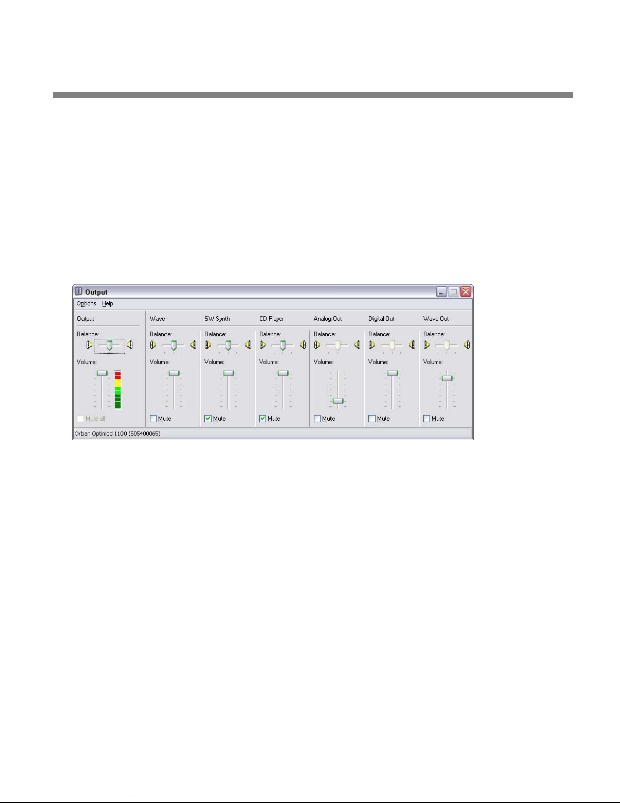
OPTIMOD-PC INSTALLATION
Both mixers are functionally identical. They have four inputs:
• Analog Left/Right
• Digital 1 Input
• Digital 2 Input
• WAVE Out from PC.
2-25
About the Interaction between the OPTIMOD-PC Input Mixers
and the Microsoft Windows Mixer
Figure 2-8: MS Mixer Output
Most PCs have a master WAVE volume control that you can access from the speaker
icon in the System Tray (Figure 2-8). If you are using the OPTIMOD-PC as your computer’s default sound card, OPTIMOD-PC’s driver defeats the MS Mixer’s Wave In
Volume (Figure 2-9), forcing it to full gain. This attempts to ensure that the
OPTIMOD-PC I/O Mixer’s gain is calibrated correctly. The reason it cannot predictably
do this is that there is another WAVE gain control in series with the master volume
control. This control is located in the Windows Mixer.
Right clicking the speaker icon and choosing Volume opens the Windows Mixer. This
mixer has several controls. One is the Output control, which is the same control that
appears when you click the speaker icon and (to repeat) is defeated by the
OPTIMOD-PC driver. The other controls are typically (1) WAVE (the culprit mentioned above), (2) Music Synthesizer, and (3) CD Player controls. Your computer’s
operating system sums the outputs of these controls; their sum is the WAVE signal
applied to the WAVE inputs in the OPTIMOD-PC I/O Mixer.
Page 78
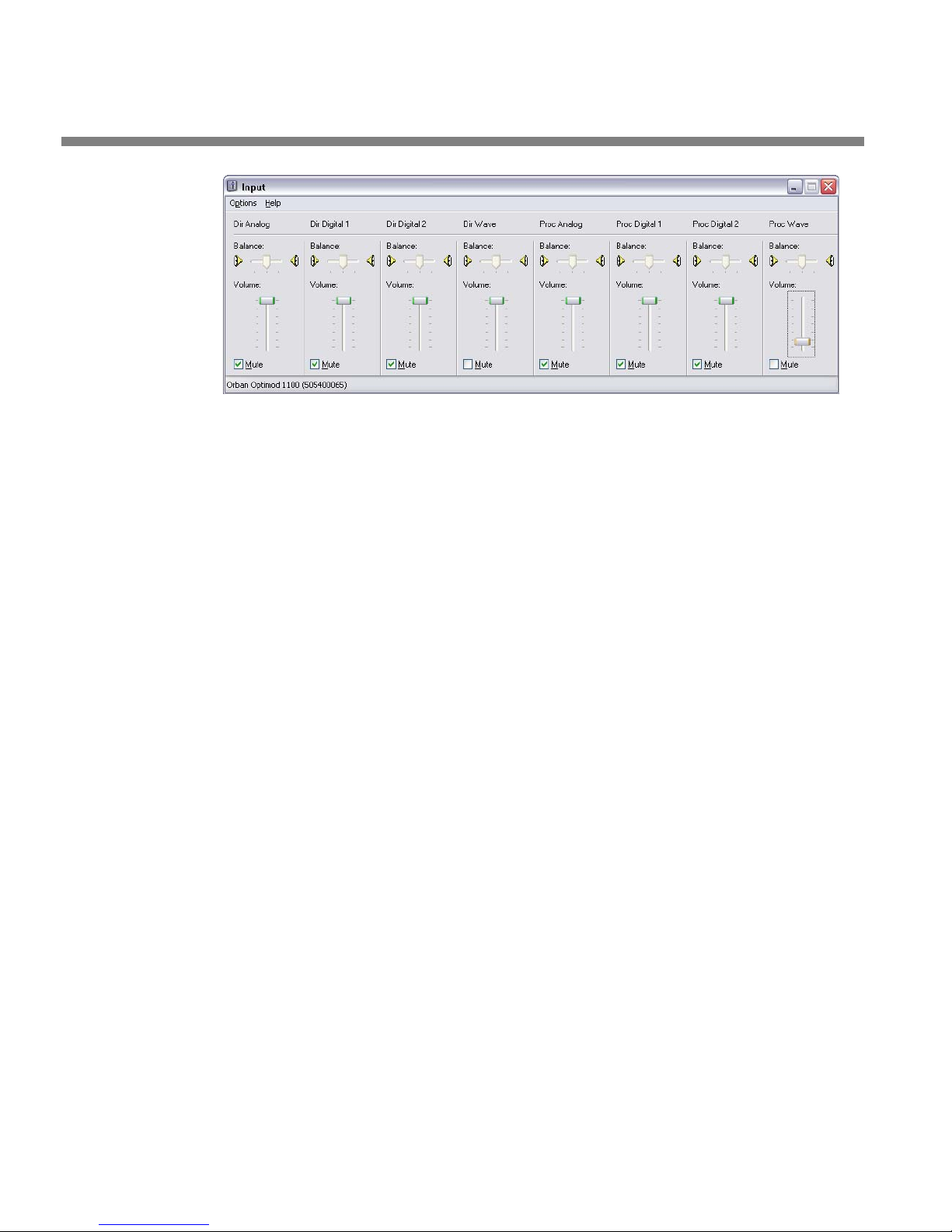
2-26
INSTALLATION ORBAN MODEL 1101
Figure 2-9: MS Mixer Input
To ensure correct calibration of the OPTIMOD-PC I/O Mixer WAVE Input, set the
Windows Mixer WAVE control to full-scale. There are certain applications (at this
writing, RealPlayer® is one of them) whose dedicated volume controls operate by
resetting the Windows Mixer WAVE control. If the WAVE level in the OPTIMOD-PC
mixer seems unexpectedly low, check the setting of the Windows Mixer WAVE control to ensure that it is still at full scale and that another application has not
changed it.
There is also an OPTIMOD-PC record volume control available in C
PANELS>SOUNDS AND AUDIO DEVICES>AUDIO—click VOLUME in the SOUND RECORDING
box to see it. The Recording or Input Mixer mirrors with the OPTIMOD-PC mixer and
can therefore be accessed by any standard Windows audio application that enumerates Windows audio controls.
Because OPTIMOD-PC supports the Windows Mixer API, Windows makes the controls associated with OPTIMOD-PC appear automatically in the MS Mixer Input and
Output. However, it is better to use the Orban application to adjust these controls
because the faders in the Orban I/O mixer have better resolution and the Orban
mixer has more functionality.
ONTROL
Input Setup Procedure
1. Adjust the Analog Input Reference Level control.
[If you will not be using OPTIMOD-PC’s analog input, continue with step 6 on
page 2-30.]
A) In the I/O Mixer, click the C
B) Set the A
whether you are driving the OPTIMOD-PC’s analog input with professional or
consumer equipment, respectively.
If the A
the A
material to the analog input, reset the A
+4DBU.
NALOG INPUT REFERENCE LEVEL to +4DBU or –10DBV depending on
NALOG INPUT REFERENCE LEVEL is set to –10DBV and the level meter on
NALOG L/R INPUT control hits full scale when you apply normal program
ONFIGURATION tab (see Figure 2-6 on page 2-21).
NALOG INPUT REFERENCE LEVEL to
Page 79

OPTIMOD-PC INSTALLATION
2-27
ANALOG L/R INPUT controls are found on the PROCESSOR MIXER and DIRECT
MIXER pages.
Using +4dBu as the reference level, the system is calibrated correctly
when the I
duce –20dBfs at the WAVE output for recording/encoding applications.
The input stage has 20dB of headroom prior to the Input Level Control.
Hence, a +4dBu tone at the analog input indicates –20dB on the analog
input level meter. If the level meter hits full-scale when the A
REFERENCE LEVEL is set to +4DBU, you are exceeding a peak level of approximately +24dBu at OPTIMOD-PC’s analog input and you must reduce
the output level of the device driving OPTIMOD-PC.
NPUT LEVEL CONTROL adjusted to 0dB (maximum). This will pro-
NALOG INPUT
2. Adjust the Analog Output Reference Level control.
If you are using the Processing w/Limiting Output: An output level fader
setting of –12dB produces approximately +4dBu at the output with normal arbitrary processed audio.
When the analog output is set to receive PROCESSING WITH LIMITING, a
–20dBfs 1kHz sinewave tone produces –18dB at the Analog Output Meter
and +2dB on an external meter with VU ballistics calibrated so that 0 VU
= +4 dBu and connected to Optimod-PC’s analog output. This assumes
that:
• The Active Preset is Rock Medium.
• The
The Optimod-PC digital and WAVE output meters indicate –6 dBfs when
their respective OUTPUT LEVEL controls are set to 0 dB (maximum).
LIMITING control in the preset is set to 0.0dB.
If you are using the Direct Mixer Output: The Direct Mixer Output is used
when Optimod-PC is used without processing as a sound card only.
Set the A
NALOG OUTPUT LEVEL CONTROL to 0dB (maximum) to achieve correct level
calibration for the corresponding analog output reference level (+4 dBu or –10
dBV).
• When the Analog Output is set to DIRECT MIXER, a –20dBfs 1kHz sine-
wave file produces –20dB at the Analog Output Meter and 0dB on an
external meter with VU ballistics connected to Optimod-PC’s analog
output. This assumes that the external meter is calibrated so that 0 VU
= +4 dBu.
• When the A
A
NALOG OUTPUT control is set to 0dB (maximum), the system is properly
calibrated and set to unity gain with 20dB of headroom.
• When the ANALOG INPUT REFERENCE LEVEL is set to +4dBu, a +4dBu input
level produces a –20dBfs digital output signal at the D
outputs, and a –20dBfs input signal from the D
produces a +4dBu output level when the A
LEVEL is set to +4dBu.
NALOG INPUT control is set to 0dB (maximum) and the
IGITAL or WAVE
IGITAL or WAVE INPUTS
NALOG OUTPUT REFERENCE
Page 80
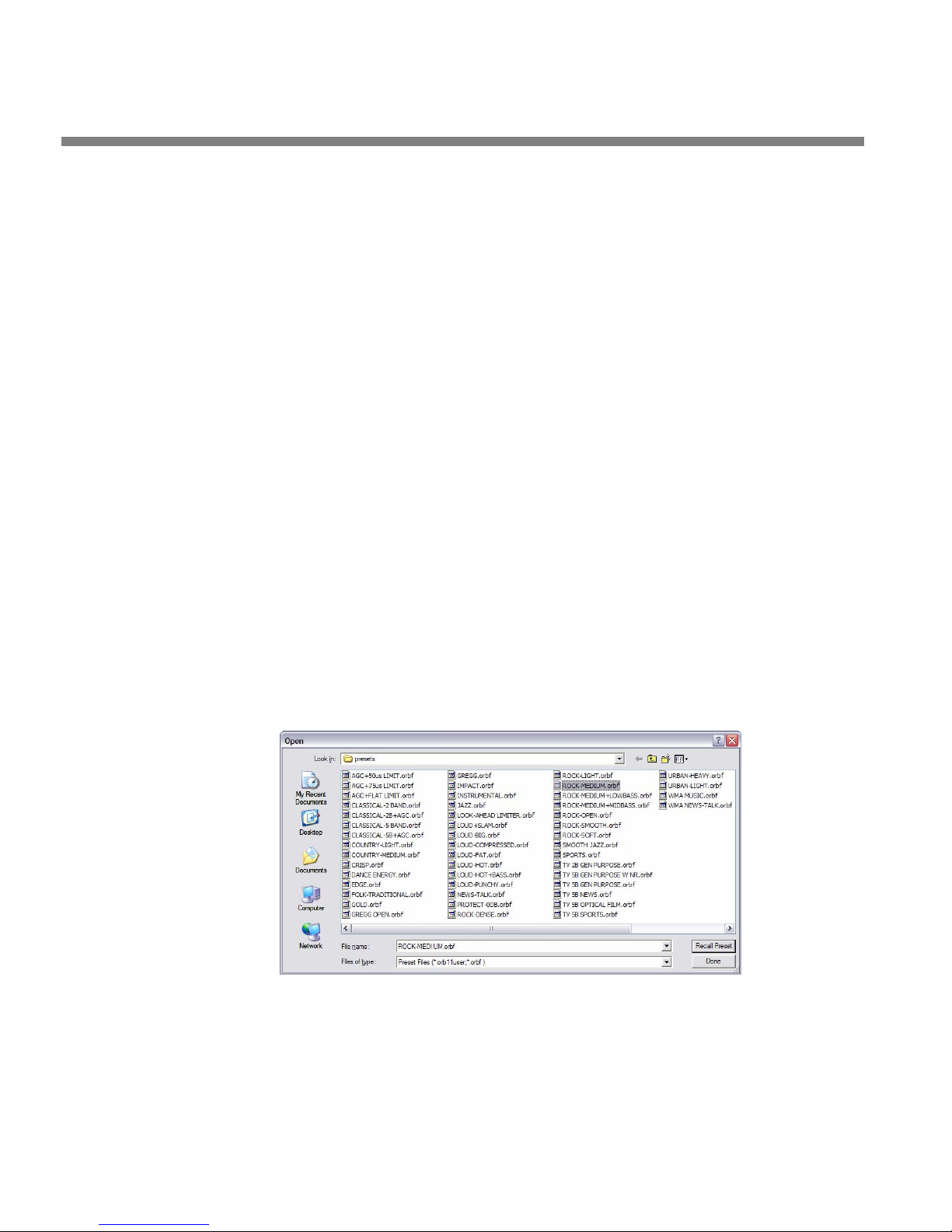
2-28
INSTALLATION ORBAN MODEL 1101
• If you use a digital reference level higher than –20dBfs or an analog
reference level higher than +4dB, you will lose headroom if you wish
to retain unity gain. Because the analog input’s absolute clipping level
is +24 dBu (with the A
ducing the setting of Optimod-PC’s A
gain the lost headroom. For example, a +8 dBu analog reference level
can provide no more than 16 dB of headroom. For this reason, elevated reference levels are not recommended for use with Optimod-PC
unless you fully understand the headroom tradeoffs that result.
NALOG INPUT REFERENCE LEVEL set to + 4 dBu), re-
NALOG INPUT control will not re-
3. Select the Stereo/Mono input mode for the analog input.
You can choose whether the fader operates on both stereo channels applied to
the analog input or if it operates in mono, driving the left and right channels of
the processing with identical signals. The choices are:
• Stereo
• Mono from the left-channel input
• Mono from the right-channel input
• Mono from the sum of the left and right channel inputs
Choose the functionality you want from the STEREO/MONO drop-down list (found
on the I/O mixers below the corresponding faders). The default is S
TEREO.
4. Adjust the Processor mixer analog input fader.
This step adjusts the drive to OPTIMOD-PC’s audio processing so that it operates
in its preferred range.
A) Open the ROCK-MEDIUM factory processing preset.
a) On the Orban Control application, choose F
The Open Preset dialog box appears.
b) Click ROCK-MEDIUM in the preset list.
ILE/OPEN PRESET.
Page 81

OPTIMOD-PC INSTALLATION
2-29
The ROCK-MEDIUM preset becomes active. The dialog box remains open
until you explicitly close it by clicking D
ONE.
B) Calibrate using tone—feed a test tone at your reference level to OPTIMOD-PC.
[Skip this step if you are using program material to calibrate OPTIMODPC to your standard studio level. Skip to step (C) on page 2-29]
a) If you are not using a studio level controller, feed a tone through your
console or mixer at the level at which you normally peak program material
(typically 0 VU if your console uses VU meters).
If you are using a studio level controller that performs an AGC function,
such as another OPTIMOD-PC or an Orban 6300, adjust it for normal
operation.
b) In the I/O Mixer, click the C
c) Click the P
d) Set the A
ROCESSOR MIXER tab.
NALOG L/R INPUT fader to make the MIXER OUTPUT meter indicate
ONFIGURATION tab.
–20dBfs.
For more information, refer to the notes under step 1 on page 2-26.
e) Note the setting of the ANALOG L/R INPUT fader. Click the DIRECT MIXER tab
and set the A
NALOG L/R INPUT fader to the same value.
f) Skip to step 5 on page 2-30.
C) Calibrate using program: Feed normal program material to OPTIMOD-PC’s
analog input.
[Skip this step if you are using tone to calibrate OPTIMOD-PC to your
standard studio level—see step (B) above.]
a) Play program material from your studio, peaking at the level to which you
normally peak program material (typically 0 VU if your console uses VU
meters).
b) In the Mixer application, click the C
c) Verify that AGC
Refer to step (0 on page 2-20.
is set to ENABLED.
ONFIGURATION tab.
d) Click the PROCESSOR MIXER tab.
e) Set the A
NALOG L/R INPUT fader to make the AGC GAIN REDUCTION meter (on
the main meter screen in the Orban Control application) indicate an
average of 10 dB gain reduction when normal levels are applied to the
OPTIMOD-PC’s analog input.
If necessary, drag the Mixer window so that the AGC GAIN REDUCTION me-
ter is visible.
Page 82

2-30
INSTALLATION ORBAN MODEL 1101
If the AGC gain reduction meter averages less than 10dB gain reduction
(higher on the meter), or if the G
material is present, turn the A
If the AGC gain reduction meter averages more gain reduction (lower on
the meter), turn the A
NALOG L/R INPUT fader down.
ATE indicator stays on when program
NALOG L/R INPUT fader up.
f) Note the setting of the ANALOG L/R INPUT fader. Click the DIRECT MIXER tab
and set the A
NALOG L/R INPUT fader to the same value.
g) When finished, reset AGC
to DISABLED, if required.
5. Adjust the Analog L/R Input Balance Control. (optional)
[Skip this step if the channels are already balanced satisfactorily.]
[This step can only be accurately performed with test tones.]
A) Click the P
ROCESSOR MIXER tab.
B) Make your console or other program source output a correctly balanced test
tone, such that its left and right output level meters indicate identical levels.
C) If the M
tically, adjust the P
IXER OUTPUT meters on the PROCESSOR MIXER tab do not indicate iden-
AN/BALANCE control in the ANALOG L/R INPUT block until they
do.
6. Adjust the remaining input faders. (optional)
If you are using any of the other inputs (D
IGITAL 1, DIGITAL 2, WAVE OUT FROM PC),
perform steps 3 through 5 (above) for these sources, substituting the appropriate
fader and balance control for the analog control referenced in these steps. Be
sure that you are driving only the input you are adjusting; you can mute the
other inputs by checking their M
You can use a program like Adobe Audition to generate .WAVE files for
tone calibration.
UTE boxes temporarily.
7. Set up the automatic backup feed function. (optional)
You may wish to configure your system so that OPTIMOD-PC will automatically
switch to a backup feed if a primary feed fails. The A
puts can be programmed to mute automatically if the D
an AES3 input signal, and to unmute if the D
To do this, check (by clicking) the B
both) of the A
of the D
IGITAL 2 INPUT then fails, the ANALOG L/R INPUT will automatically unmute.
D
IGITAL 1 INPUT will automatically unmute only the DIGITAL 2 INPUT. If the
NALOG L/R and DIGITAL 2 in-
IGITAL 1 input is locked to
IGITAL 1 input loses lock.
ACKUP INPUT FOR DIGITAL 1 box on either (or
NALOG L/R and DIGITAL 2 inputs. If both are checked, then a failure
Page 83
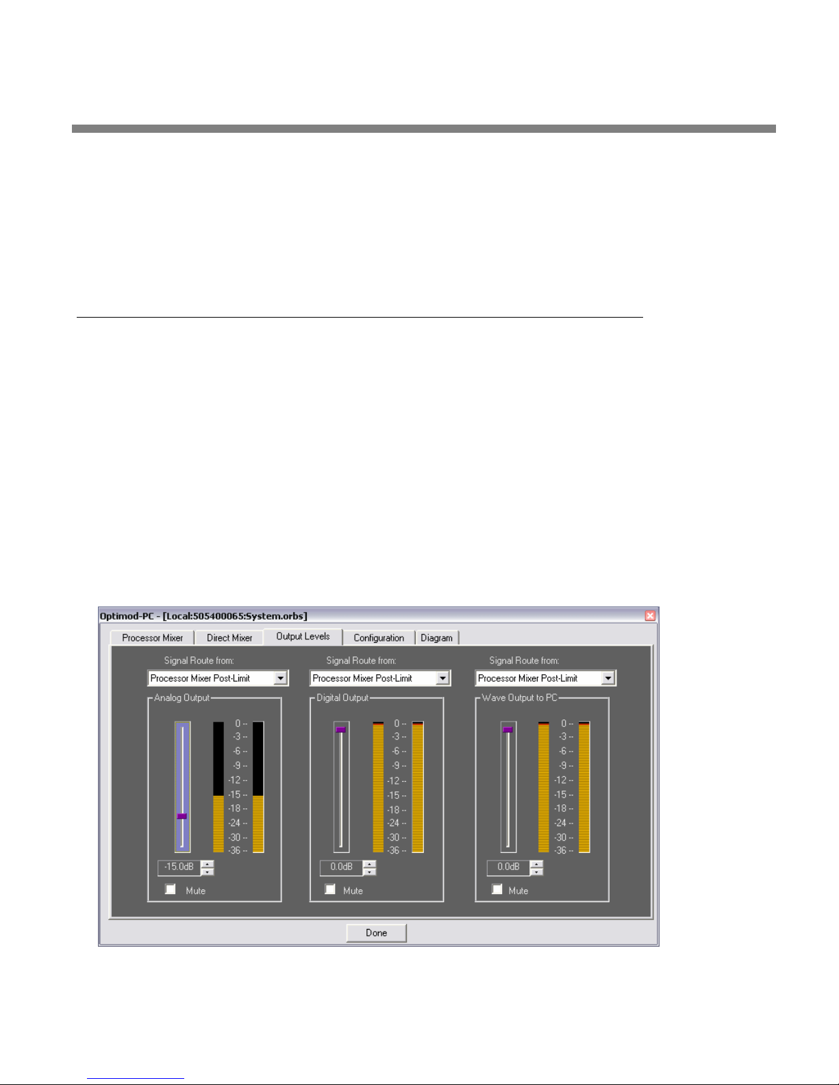
OPTIMOD-PC INSTALLATION
You can set these functions separately on the Processor mixer and the Direct Mixer. The two mixers will behave independently according to their
individually set programming.
If both “backup for digital 1” and “mute” are selected, the backup function will override the mute function.
2-31
Output and Routing Switcher Setup
The three-switch output routing switcher determines the feed to:
• The OPTIMOD-PC card’s stereo analog output
• The OPTIMOD-PC card’s two AES3 digital outputs, which emit identical sig-
nals in v1.0 software.
• The WAVE input to the computer.
Each output can receive any of the following four sources:
• The WAVE output from the computer
• The output of the direct mixer
• The output of the OPTIMOD-PC audio processing that follows all processing
Figure 2-10: Output Levels Page in I/O Mixer
Page 84

2-32
INSTALLATION ORBAN MODEL 1101
except final peak limiting
• The output of the OPTIMOD-PC audio processing that follows all processing,
including peak limiting.
The “processed without limiting” output can provide a low-delay monitor feed back to live talent headphones because it has significantly lower
throughput delay than the “processed with limiting” output. Because the
look-ahead limiter contributes most of the time delay through the system, listening from the output of the multiband compressor (ahead of
the look-ahead limiter) can be more comfortable to a DJ or presenter
who is monitoring his or her voice live through headphones.
Each of the three outputs has an attenuator and a stereo peak-reading meter,
which indicates the post-attenuator level.
A) Using the drop-down menu, choose the source that feeds each output.
B) Set the output level of each output as desired, using its attenuator.
See the notes under step 2 on page 2-27 for more information on headroom and calibrating for unity input/output gain.
Refer to Setting Output/Modulation Levels on 1-29 of this manual for advice on setting output levels and on their relationship to headroom.
C) If you wish to save the entire setup (that is, the settings of all controls in all
tabbed pages), click S
cation. Then follow the prompts.
Saving a setup is useful mainly if you wish to be able to paste this entire
setup to another OPTIMOD-PC card later. Any changes you have made to
the setup of the currently active card will be saved automatically for that
card when you click D
losing changes you made. See step (2.B) on page 2-19.
AVE SETUP on the File menu in the Orban Control appli-
ONE; it is unnecessary to use SAVE SETUP to avoid
The Direct Mixer
The Direct Mixer looks the same as the Processor Mixer (see Figure 2-7 on page 2-
24). The Direct Mixer determines the gain applied to input signals before these signals are sent directly (without OPTIMOD-PC processing) to the output routing
switcher. If the output attenuator in the routing switcher is set to “0dB” and the
analog input and output reference levels are set identically (to +4dBu or –10dBv),
then the Direct Mixer faders will indicate the input/output gain directly in dB.
The default settings of “0dB” provide unity gain in and out of the OPTIMOD-PC card
for both the analog and the digital inputs. If you want to change a reference level
between a source and destination (for example, from –16dBfs to –18dBfs), you can
do so by adjusting the fader corresponding to the source (in our example, by setting
it to –2dB).
Note that you are limited by input headroom: if you set the D
OPTIMOD-PC’s digital output level cannot exceed –2dBfs because this level corresponds to 0dBfs at OPTIMOD-PC’s digital 1 input.
IGITAL 1 fader to –2dB,
Page 85
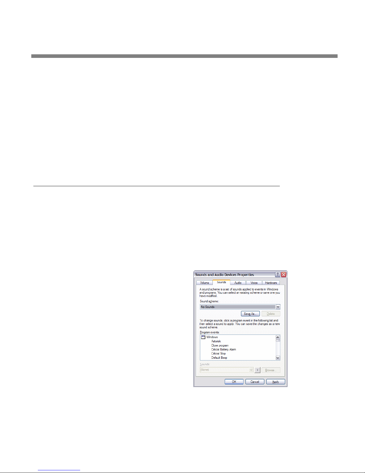
OPTIMOD-PC INSTALLATION
If you are using a digital input and an analog output, note that OPTIMOD-PC’s internal gain for both input and output is such that 0dBfs = +24dBu. OPTIMOD-PC’s
output line amplifiers can drive +24dBu into a balanced load. However, the maximum analog output level they can drive into an unbalanced load is +18dBu. Therefore, to match analog and digital clipping levels when driving an unbalanced load
NALOG REFERENCE LEVEL = +4dBu, set the ANALOG OUTPUT fader to –6dB.
with A
The ANALOG OUTPUT fader is located in the OUTPUT LEVELS page.
If you are mixing more than one active input, be careful not to exceed the headroom of OPTIMOD-PC’s mix bus, whose peak level is indicated by the M
meters on both the P
do not permit the “0”
ROCESSOR MIXER and DIRECT MIXER pages. To prevent clipping,
SEGMENT OF this meter to light.
IXER OUTPUT
2-33
Interfacing OPTIMOD-PC with WAVE Devices
Turning Off Windows Sounds
If OPTIMOD-PC is the Windows Preferred or Default Device, to prevent Windows’
OS-generated and application-generated sounds from going “on the air” or over
your stream, you must turn them off.
This caveat applies only when you are using OPTIMOD-PC’s WAVE inputs.
If you are using only OPTIMOD-PC’s hardware inputs and have the WAVE
inputs turned off in the OPTIMOD-PC I/O mixer, then the system WAVE
sounds will not mix with your desired program material.
• In Windows XP, navigate to CONTROL
PANEL/SOUNDS AND AUDIO DEVICES/SOUNDS. In the
“sound scheme” drop-down box, choose N
SOUNDS.
O
Applying Output from WAVE Applications to OPTIMOD-PC
Windows mixes the audio outputs of all simultaneously operating WAVE applications that have been
set up to feed OPTIMOD-PC as a Windows sound
device. The resulting mix feeds the OPTIMOD-PC’s
OUT FROM PC faders in both the PROCESSOR
WAVE
MIXER and DIRECT MIXER pages. Because the volume
controls on most WAVE applications are attenuators only (providing no gain at any setting), it is
usually wise to set them to maximum and to set levels via the OPTIMOD-PC Mixer’s
OUT FROM PC faders.
WAVE
Windows Media Player does not allow you to specify its target Windows
Sound Device, instead always feeding the Windows Default Sound De-
Page 86
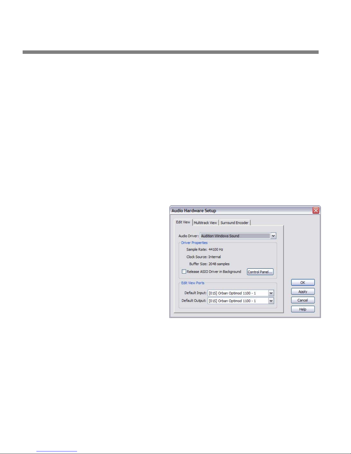
2-34
INSTALLATION ORBAN MODEL 1101
vice. Therefore, to use WMP as a playout application, you must set
OPTIMOD-PC as the Default Sound Device in Windows.
The OPTIMOD-PC DirectSound Driver allows digital audio playout applications to
output multiple sources simultaneously to one sound device. This eliminates the
need for multiple sound cards or sound cards with multiple sound devices for each
player and allows multiple players to mix automatically in automated operation,
independent of sample-rate and/or bit-rate. If individual outputs for each player are
not needed, this feature of DirectSound eliminates the need to mix all player outputs together externally,
Please note that some applications (like RealPlayer, as of this writing)
have volume controls that affect the Windows master volume instead of
just their own output levels. See About the Interaction between
OPTIMOD-PC’s Input Mixers and Your PC’s Built-In Mixer on page 2-25.
Note also that if the sample rate of the source material is different from
48 kHz (OPTIMOD-PC’s native sample rate), the operating system will apply the appropriate sample rate conversion.
Applying OPTIMOD-PC’s Output to WAVE Devices
OPTIMOD-PC’s WAVE output
looks like the output of a
sound card to the host computer. Any application that
can receive the output of a
standard Windows WAVE device can use this output. Most
such applications have a menu
item that lets you select the
particular WAVE device from
which they are receiving input; select “OPTIMOD-PC.”
Once you have done this, you
can set the drive level to the
application via the WAVE
output attenuator in the
OPTIMOD-PC I/O Mixer. You
can select the source that drives the application (PC WAVE output, output of Direct
Mixer, output of OPTIMOD-PC pre-limiter, or output of OPTIMOD-PC post-limiter)
via the drop-down selector located above this attenuator.
For example, the figure shows Adobe Audition 2.0 Audio Hardware Setup.
If you have more than one OPTIMOD-PC card installed, these will be known to Windows as “Orban Optimod 1101 (serial number of card #1),” “Orban Optimod 1101
(serial number of card #2)),” etc.
This is mainly relevant to users running multiple instances of a streaming
encoder program like Orban Opticodec-PC, Real/Helix Producer or Windows Media Encoder. Typically, each instance of the streaming program
is connected to a separately named OPTIMOD-PC WAVE device. For example, if you were running two streams, one instance of HELIX Producer
Page 87
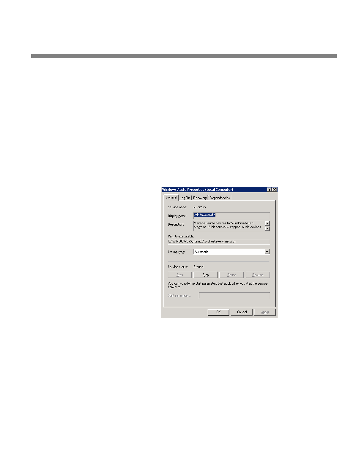
OPTIMOD-PC INSTALLATION
2-35
would be connected to “Orban OPTIMOD-1101 (serial number of card
#1)” and the other instance would be connected to “Orban OPTIMOD1101 (serial number of card #2).”
Because Windows XP fully supports OPTIMOD-PC’s multiclient driver, it is
possible to drive several record/encode applications from a single output
of OPTIMOD-PC. For example, this would allow the output of one
OPTIMOD-PC to drive several instances of an encoder, several encoders,
or any other record application.
Enabling the Windows 2003 Server Audio Service
By default, some versions of Windows 2003 server have the Audio Service Disabled.
To use audio Wave I/O with OPTIMOD-PC, you must enable the Windows 2003
Server Audio Service. This service is unnecessary if you are only using OPTIMOD-PC
with its hardware audio I/O.
Do one of the following:
1. In Windows, navigate to:
C
ONTROL PANEL > ADMINISTRATIVE
TOOLS > SERVICES > WINDOWS AUDIO >
PROPERTIES.
A) Set the S
UTOMATIC.
A
B) Click S
TART.
TARTUP TYPE to
C) Click OK.
…or
2. Enable and configure the Windows audio service.
A) Navigate to C
ONTROL PANEL > SOUNDS AND AUDIO DEVICES
B) Check “Enable Windows Audio.”
If the Windows Audio Service is already enabled, the dialog box will not
appear. The dialog box will not reappear unless Windows Audio Service
is disabled in C
AUDIO > PROPERTIES.
ONTROL PANEL > ADMINISTRATIVE TOOLS > SERVICES > WINDOWS
Page 88
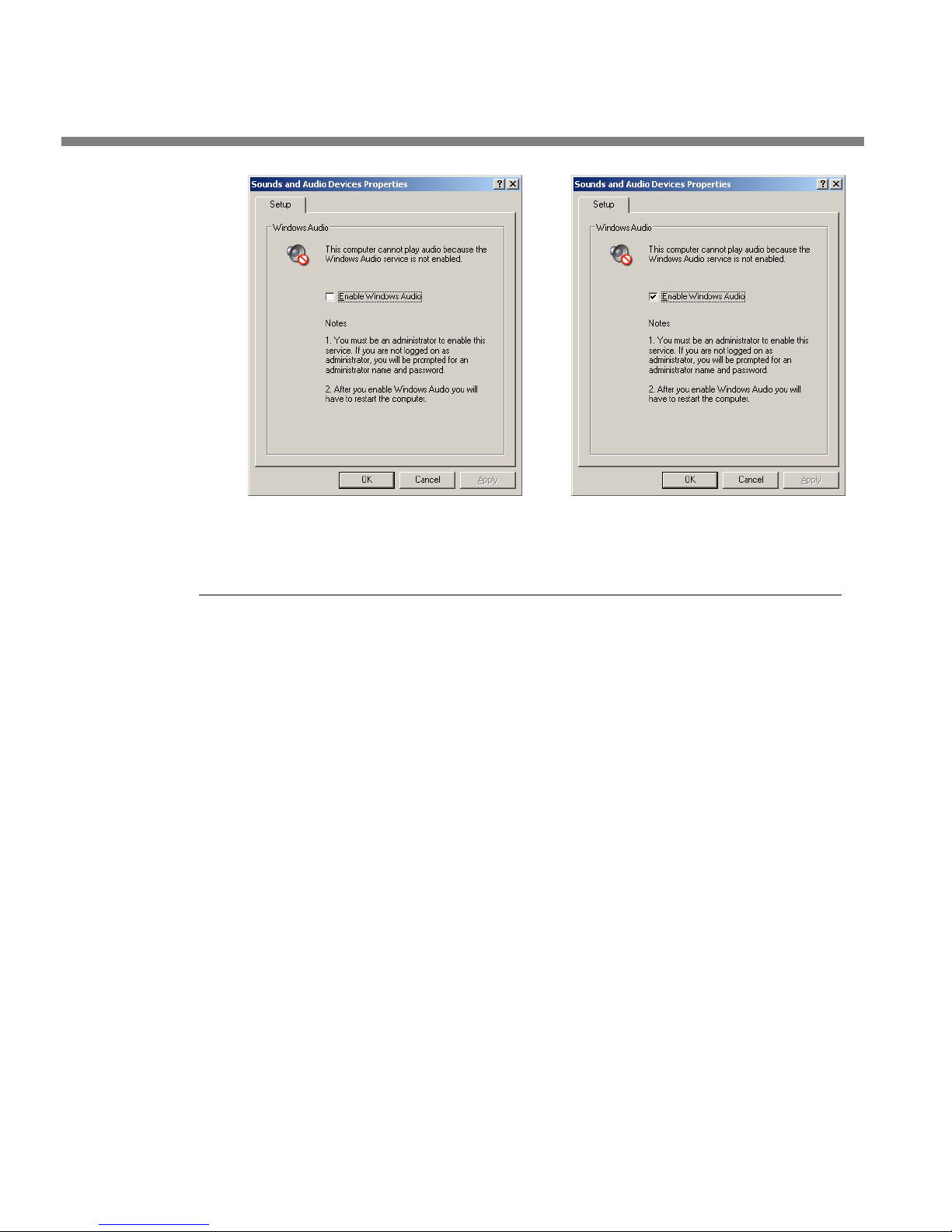
2-36
INSTALLATION ORBAN MODEL 1101
Problems and Possible Causes
Always verify that the problem is not the source material being fed to OPTIMOD-PC,
or in other parts of the system.
When I first turn on my computer, the sound seems wrong.
This is normal. Upon boot, the OPTIMOD-PC driver loads a “placeholder” preset and
I/O setup into the OPTIMOD-PC’s DSP so that the card will pass audio. After the
OPTIMOD-PC Service application starts (as part of the computer’s boot sequence), it
will automatically load the last active preset and I/O setup.
The driver does not restore the Processing Delay, AGC, and I/O Lowpass
Filter Configuration parameters at startup. They are restored at startup if
the OPTIMOD-PC service is being started automatically. If the OPTIMODPC service is not being started automatically, these parameters will be restored when the OPTIMOD-PC Control application is launched.
All others IO settings are restored when the driver loads.
When I Launch the OPTIMOD-PC control application, the meters do not move and I
cannot control my card.
Unless you have only one OPTIMOD-PC card installed in your computer, you must
connect the application to a given card (via the C
control it. This is because the Control Application is designed to address more than
one card in multi-card installations. See the steps starting with step 4 on page 2-4.
I can’t connect to a given OPTIMOD-PC card from my network.
You must check the ALLOW NETWORK TO ACCESS LOCAL CARDS box in the CARDS AND
SECURITY ADMINISTRATION dialog box for that card.
Other possible causes are:
ONNECT Menu item) before you can
Page 89

OPTIMOD-PC INSTALLATION
2-37
• Your computer’s firewall is blocking the connection. See page 2-42.
• Password is wrong.
• The target card is open on another computer on the network.
• The system that houses the target card is not on.
• The Orban Windows service routine,
OptimodPcService, is not running in the
computer housing the target card.
• The Orban Windows service routine has malfunctioned. If all else fails, try end-
ing and then restarting
OptimodPcService in the Windows Task Manager:
A) Right-click the Windows task bar and choose “Task Manager.”
B) Click the Process tab and
OptimodPcService to highlight it.
C) Click the “End Process” button.
D) Right-click
I get clicks when I source my WAVE material from a CD.
OptimodPcService and choose “Start process.”
CD audio playback can sometimes have dropouts if the CD player is being accessed
by the IDE controller using PIO mode. Usually, this can be fixed by setting the IDE
controller to DMA mode. Here are the steps to change the setting on Windows XP:
A) Open the S
B) Select the H
C) Select D
D) Expand the node labeled I
E) Right-click the first device labeled S
ROPERTIES.
P
YSTEM control panel.
ARDWARE tab.
EVICE MANAGER...
DE ATA/ATAPI CONTROLLERS.
ECONDARY IDE CHANNEL and choose
F) Select the A
G) Change the T
DVANCED SETTINGS tab.
RANSFER MODE dropdown menu from “PIO only” to “DMA if
available.”
H) Repeat steps (E) through (G) for any other devices labeled S
CHANNEL.
I get clicks when I source my WAVE material from my computer’s hard drive.
If Windows XP detects several hard disk read errors in a row, it will automatically set
the hard disk data transfer mode, usually DMA, to PIO. This can cause clicks in the
OPTIMOD-PC audio if the hard drive is sourcing the WAVE material driving
OPTIMOD-PC. See I Get Clicks When I Source My WAVE Material from a CD above.
Note that Windows’ automatically setting the HD data transfer mode to PIO can be
an early warning of impending hard disk failure. It is wise to search the Windows
System log for instances of hard drive read or write problems (C
ADMINISTRATIVE TOOLS > EVENT VIEWER > SYSTEM LOG).
ECONDARY IDE
ONTROL PANEL >
Page 90

2-38
INSTALLATION ORBAN MODEL 1101
I get clicks in the 1101’s WAVE output.
Wrap-around glitches can occur at the peaks of OPTIMOD-PC’s processed output
when you are recording or streaming it via the Windows WAVE mechanism at sample rates other than 48 kHz and OPTIMOD-PC’s WAVE output level is set to 0 dBfs.
We believe that overshoots in the computer’s WAVE sample rate converter cause
this; it is not caused by OPTIMOD-PC’s DSP. To prevent such glitches, set the 1101’s
WAVE output level lower than –0.5 dBfs for 44.1 kHz recording/streaming and lower
than –1.0 dBfs for 32 kHz recording/streaming.
The 1101’s hardware outputs do not have this issue.
I am running Windows 2003 and I cannot get audio to pass through OPTIMOD-PC’s
WAVE inputs and outputs.
See Enabling the Windows 2003 Server Audio Service on page 2-35.
Meters on Optimod-PC Control Application freeze temporarily but audio continues
to be processed normally.
This is by design. The software thread controlling the meters is given lower than
“normal” priority in Windows to prevent the meters from interrupting important
threads that maintain audio continuity through the Windows WAVE mechanism.
RFI, hum, clicks, or buzzes
A grounding problem is likely. Review the information on grounding on page 2-17.
OPTIMOD-PC has been designed with substantial RFI suppression on its analog and
digital input and output ports. It will usually operate adjacent to high-powered
transmitters without difficulty. In the most unusual circumstances, it may be necessary to reposition the host computer to reduce RF interference, and/or to reposition
OPTIMOD-PC’s input and output cables to reduce RF pickup on their shields.
The AES3 inputs and output are transformer-coupled and have good resistance to
RFI. If you have RFI problems and are using analog connections on either the input
or output, using digital connections will probably eliminate the RFI.
Poor peak level control
OPTIMOD-PC audio processing ordinarily controls its output peak levels to an accuracy of ±2% when operated with 48 kHz output sample rate. As explained in the
note on page 1-24, output sample rate conversion will slightly compromise this control because the peak control occurs with reference to individual sample values at 48
kHz. The converted samples no longer have the same peak values as the 48 kHz
samples, and some values can be slightly higher. However, the overshoot of the converted signal almost never exceeds 0.5 dB and is therefore not a significant problem.
Using the analog output will cause similar amounts of overshoot because the samples in the transmitter or encoder are not synchronous with the peak-controlled
samples in OPTIMOD-PC. Further, analog connections can cause analog-domain
overshoot if the connection is not phase linear and has a low-frequency cutoff of
greater than 0.15Hz (at –3dB).
Audible distortion
Make sure that the problem can be observed on more than one sound system and at
several locations.
Page 91

OPTIMOD-PC INSTALLATION
Verify that the source material at OPTIMOD-PC's audio inputs is clean. Heavy processing can exaggerate even slightly distorted material, pushing it over the edge into
unacceptability.
The subjective adjustments available to the user have enough range to cause audible distortion at their extreme settings. Advancing the F
inevitably cause distortion. (Distortion is very probable if gain reduction in the final
limiter frequently exceeds 8 dB.) Setting the L
cause audible distortion of some program material.
If you are using analog inputs, you must correctly match the headroom of the unit's
analog-to-digital (A/D) converter to the peak audio levels expected in your system. If
your peak program level exceeds the peak level you have specified, OPTIMOD-PC's
A/D converter will clip and distort. See step 1 on page 2-26.
Be sure that the output meters for the processor mixer and Direct Mixer never go
into the red. If they do, turn down the input attenuator(s) connected to the signal
causing the overload.
Audible noise in processed audio
(See also “RFI, Hums, Clicks, or Buzzes” on page 2-38.)
Excessive compression will always exaggerate noise in the source material.
OPTIMOD-PC reduces this problem with its compressor gate, which freezes the gain
of the AGC and compressor systems whenever the input noise drops below a level
set by the G
being further increased.
If you are using OPTIMOD-PC's analog input, the overall noise performance of the
system is usually limited by the overload-to-noise ratio of the analog-to-digital converter used by OPTIMOD-PC to digitize the input. (This ratio is better than 100dB.)
ATE THR (Gate Threshold) control, preventing noise below this level from
ESS-MORE control beyond “9” will
INAL LIMIT control too far will
2-39
It is important to specify the A
page 2-26). You should specify the level as the highest peak level that OPTIMOD-PC
will receive under normal operation. If, in an attempt to build in a “safety factor” or
increase headroom, you specify a higher level than this, every 1dB of extra headroom that you gain will increase OPTIMOD-PC's noise floor by 1dB.
OPTIMOD-PC's AES3 input is capable of receiving words of up to 24 bits although
the dynamic range of its input sample rate converters limits the worst-case dynamic
range to 20 bits. A 20-bit word has a dynamic range of approximately 120dB.
OPTIMOD-PC's digital input will thus never limit the unit's noise performance even
with very high amounts of compression.
In digital radio applications, if an analog studio-to-transmitter link (STL) is used to
pass unprocessed audio to OPTIMOD-PC, the STL's noise level can severely limit the
overall noise performance of the system because compression in OPTIMOD-PC can
exaggerate the STL noise. For example, the overload-to-noise ratio of a typical analog microwave STL may only be 70-75dB. In this case, it is wise to use an Orban Studio Level Controller (like an Orban 6300 or another OPTIMOD-PC) to perform the
AGC function prior to the STL transmitter and to control the STL's peak modulation.
This will optimize the signal-to-noise ratio of the entire transmission system. An uncompressed digital STL will perform much better than any analog STL. Section 1 of
this manual has a more detailed discussion.
NALOG INPUT REFERENCE LEVEL correctly (see step 1 on
Page 92

2-40
INSTALLATION ORBAN MODEL 1101
Shrill, harsh sound; excessive sibilance
Excessively high settings of the HF GAIN control can cause this problem. It can also be
caused by excessively high settings of the B5
THRESHOLD (Band 5 Compression
Threshold) control. In the latter case, you are first likely to notice the problem as
harsh sibilance on voice.
Gain pumping when high frequency energy is present
This will occur with most OPTIMOD-PC factory presets when OPTIMOD-PC’s preemphasis is set to 50 µs or 75µs. [See step 5 on page 2-23.] The gain pumping happens
because the preemphasis creates a large high frequency boost before the lookahead limiter, so the look-ahead limiter must produce large amounts of gain reduction to control peak levels.
To correct this problem, turn down the F
INAL LIMIT DRIVE control (page 3-40) until the
pumping is no longer audible (see Processing for Low Bitrate Codecs on page 3-5). It
may also be helpful to adjust band 5 so that it produces some high frequency limiting. (The AGC+75
US LIMITER factory preset illustrates this technique; see page 3-18.)
Then save your work as a User Preset.
System receiving OPTIMOD-PC’s AES digital output will not lock
Be sure that OPTIMOD-PC’s output sample rate is set to match the sample rate that
the driven system expects. Be sure that OPTIMOD-PC’s digital output format control
is set to match the standard expected by the driven system (either AES3 or SPDIF).
(See step 4 on page 2-22.)
System will not pass line-up tones at full output level/100% modulation
This is normal in OPERATE mode. Sine waves have a very low peak-to-average ratio
by comparison to program material. The processing thus automatically reduces their
peak level to bring their average level close to that of program material, promoting
a more consistent and well-balanced sound quality.
To pass line-up tones transparently, recall OPTIMOD-PC’s P
ROTECT preset. If neces-
sary, adjust its gain and save your edited preset as a User Preset.
These tones should be injected into the transmitter after OPTIMOD-PC, or
OPTIMOD-PC should be temporarily switched to P
ROTECT to pass the tones.
Alternatively, you can you can bypass OPTIMOD-PC’s processing of the tones by
patching OPTIMOD-PC’s digital output into one of its digital inputs. This leaves you
with one analog or one digital input into which you can connect the unprocessed
audio. Use the remaining unused input to receive the output of the tone generator.
Use the Direct mixer to mix the tone generator and processed signal as desired. In
OPTIMOD-PC’s Output Levels tab (in the I/O mixer), assign to the Direct Mixer the
OPTIMOD-PC output driving your target system.
This scenario is particularly practical if the final output of the system is a
WAVE stream. Otherwise, the only remaining available output is the analog output. Of course, you can reverse the scenario by using the
OPTIMOD-PC analog output and input for the loop-through connection,
in which case the final mixed output could be the digital output.
General dissatisfaction with subjective sound quality
OPTIMOD-PC is a complex processor that can be adjusted for many different tastes.
For most users, the factory presets, as augmented by the gamut offered by the L
ORE control for each preset, are sufficient to find a satisfactory “sound.” However,
M
ESS-
Page 93

OPTIMOD-PC INSTALLATION
some users will not be satisfied until they have accessed other Modify Processing
controls and have adjusted the subjective setup controls in detail to their satisfaction. Such users must fully understand the material in Section 3 of this manual to
achieve the best results from this exercise.
2-41
Technical Support
If you require technical support, contact Orban customer service. See
http://www.orban.com/contact/
problem accurately. Know the serial number of your 1101 and the software and
driver versions are you running. (The driver version number is available through Settings/Control Panel/Sounds and Multimedia/Hardware/Orban Optimod 1101
/Properties/Driver.)
Before you return a product to the factory for service, please refer to this manual.
Make sure you have correctly followed installation steps, operation procedures, and
any appropriate troubleshooting suggestions. If you are still unable to solve a problem, contact our Customer Service department. Often, a problem is relatively simple
and can be fixed quickly after telephone or email consultation.
If you must return a product for factory service, please notify Customer Service by
telephone or email before you ship the product; this helps us to be prepared to service your unit upon arrival. In addition, when you return a product to the factory for
service, we strongly recommend you include a letter describing the problem.
Please refer to the terms of your Limited One-Year Standard Warranty, which extends to the first end user. After expiration of the warranty, a reasonable charge
will be made for parts, labor, and packing if you choose to use the factory service
facility. Returned units will be returned C.O.D. if the unit is not under warranty.
Orban will pay return shipping if the unit is still under warranty. In all cases, the customer pays transportation charges to the factory (which are usually quite nominal).
for contact information. Be prepared to describe the
Adding a Custom Logo
A user defined bitmap can be displayed at the right of the meter dialog in the PC
Control application. Separate bitmaps must be assigned to each OPTIMOD-PC that
you have configured; there is no “global” or default bitmap available.
To use this feature, create or copy a standard Windows format .bmp file and name it
logo.bmp. Then place this file in the directory associated with the desired Alias. To
identify this directory, open the Properties dialog by right clicking on the Alias name
in the Control Application’s connection list and look at the entry for "Local Folder.”
This will usually be:
c:\Program Files\Orban\OPTIMOD-PC2\[serial number]\presets\
The Control Application will automatically change the bitmap’s size so that it is displayed 120 pixels wide x 60 pixels high. (The original file will not be altered.) Build
custom logos or art to exactly 120 x 60; save the file in .bmp format.
Page 94
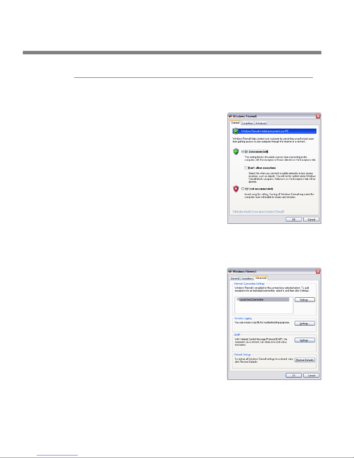
2-42
INSTALLATION ORBAN MODEL 1101
Using Windows Firewall with Optimod-PC
Depending upon your network security requirements, it may be necessary to configure a software firewall application like Windows Firewall, included with Windows
XP SP2 and higher.
1. Enable Windows Firewall:
A) Navigate to C
FIREWALL
B) Enable the On (recommended) button.
C) Select the Advanced tab.
2. Choose the network device that will be used for Optimod-PC access and
will be protected with Windows Firewall.
A) Click Settings…
ONTROL PANEL > WINDOWS
Page 95
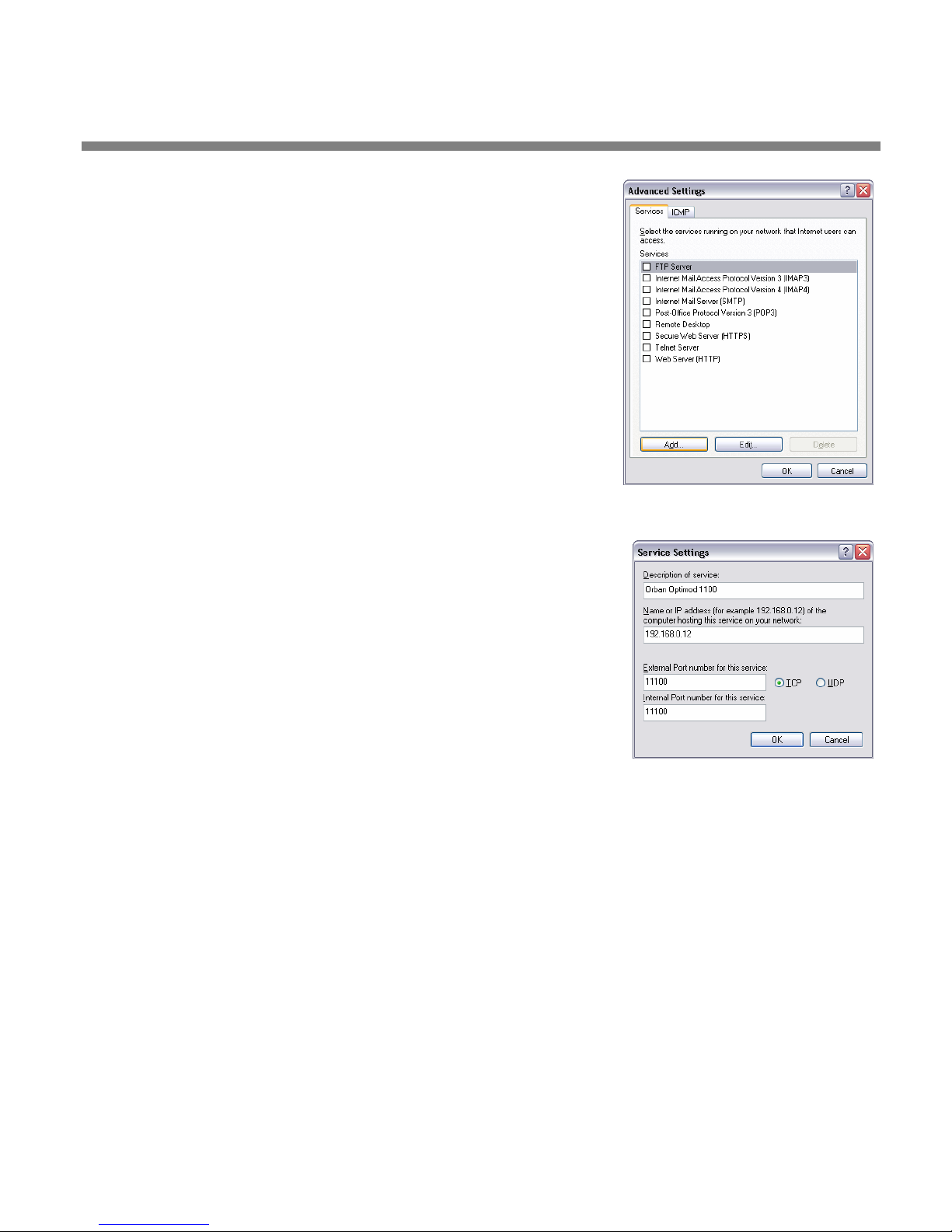
OPTIMOD-PC INSTALLATION
B) Click Add…
2-43
C) Enter the Description of the service, the name or IP address,
the External Port number, and the Internal Port number.
D) Select TCP.
The IP address will be that of the computer. To avoid
any conflict, we recommend choosing a Port higher
than 1024 that is not otherwise assigned according
to IANA:
http://www.iana.org/assignments/port-numbers
• Port 11100 is the default for the Optimod-PC Control Application.
• Port 11101 is the default for the Optimod-PC Terminal Application.
If you have 1100 and 1101 cards in the same computer, they must be assigned different ports numbers.
Page 96
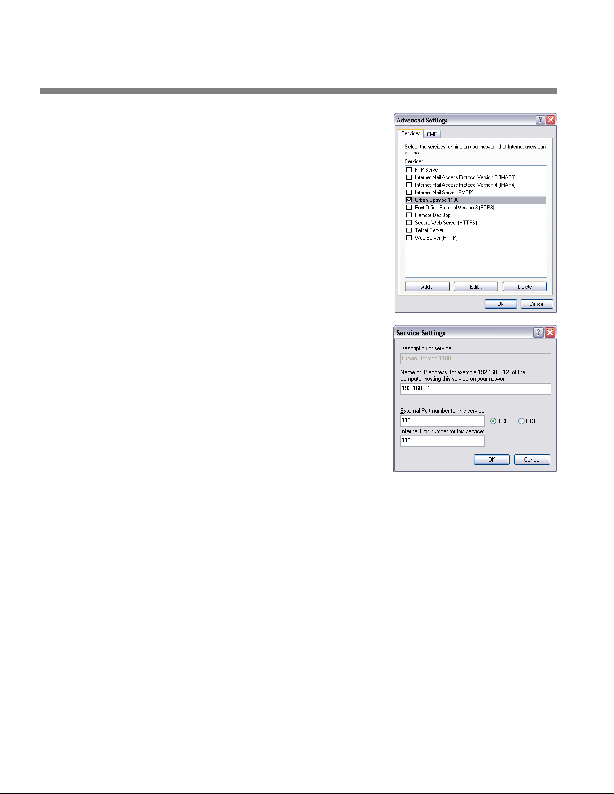
2-44
INSTALLATION ORBAN MODEL 1101
E) Select OK.
A dialog box appears, indicating
that the Orban Optimod 1101 Ser-
vice is accessible through Windows
Firewall.
F) If any changes are required (like IP ad-
dress or port):
a) Click Edit.
b) Make the changes.
c) Click OK.
NAT (Network Address Translation) Firewalls
If the computer containing Optimod-PC is on a network behind a NAT firewall, you
must configure the firewall to allow outside access to the Optimod-PC computer
from another computer outside the firewall. This is usually done via router port forwarding: The Optimod-PC port(s) are forwarded to the Optimod-PC computer by
configuring the NAT firewall accordingly. The Optimod-PC computer is then addressed with the network IP address (WAN) instead of the actual IP address of the
Optimod-PC computer.
For a single IP addressable network, each port can only be used once. Therefore, if
you have more than one computer with Optimod-PC requiring outside access, each
computer must have a unique OPTIMOD-PC port.
Refer to your router/firewall documentation for the exact configuration procedure,
paying close attention to the network security risks inherent in configuration
changes.
Page 97
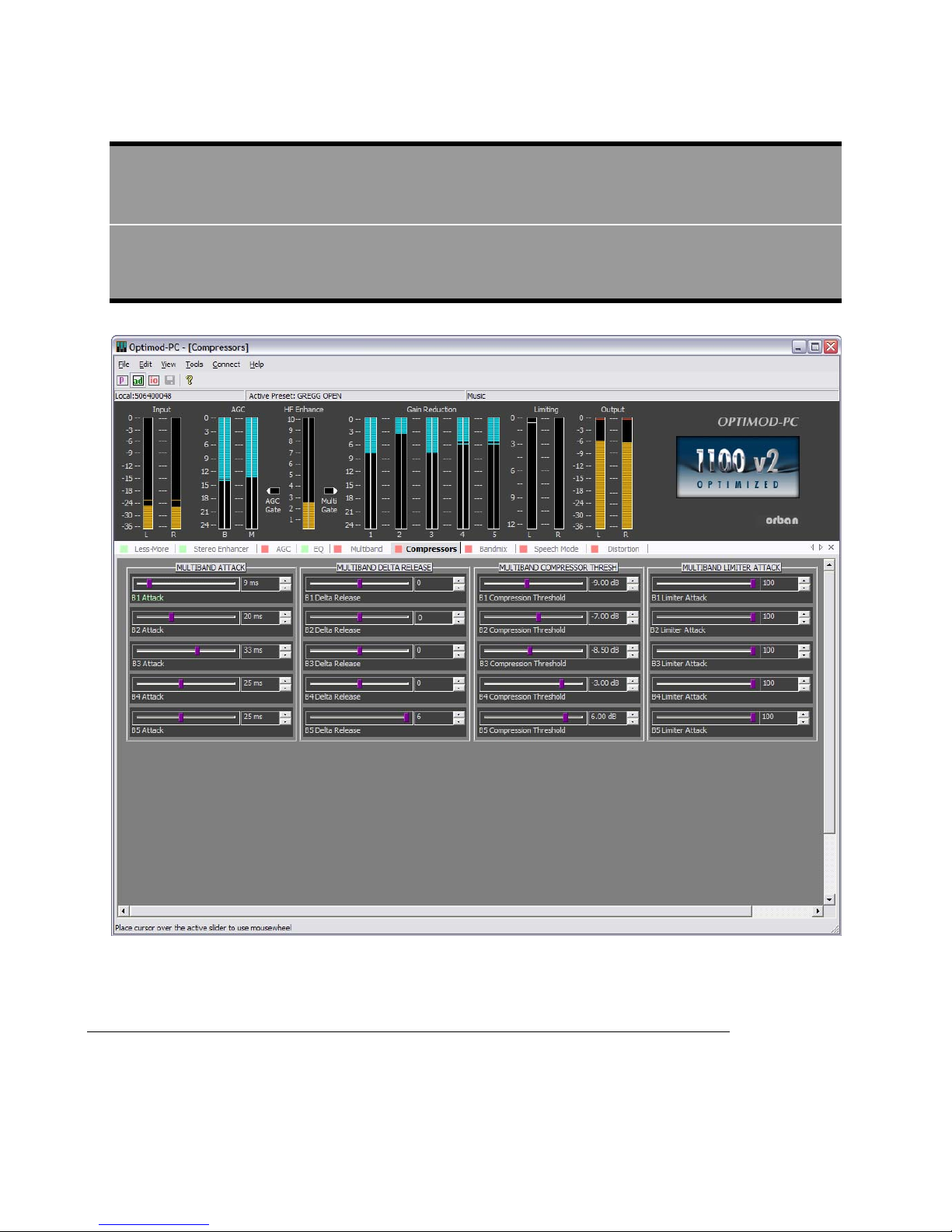
OPTIMOD-PC OPERATION
Section 3
Operation
3-1
Figure 3-1: The OPTIMOD-PC Control Application
The OPTIMOD-PC Control Application
• AGC meter shows the gain reduction of the slow AGC processing that precedes
the multiband compressor. Full-scale is 24dB gain reduction.
Page 98

3-2
OPERATION ORBAN MODEL 1101
Because the AGC is a two-band unit with Orban’s patented bass coupling
system, this meter actually reads the gain reduction of the AGC Master
band.
• Gate indicators show gate activity. They light when the input audio falls below
the threshold set by the gate threshold controls. (There are two gating circuits—
one for the AGC and one for the multiband compressor/limiter—each with its
own gate threshold control.) When gating occurs, the AGC and compressor’s recovery times slow drastically to prevent noise rush-up during low-level passages.
• Multiband gain reduction meters show the gain reduction in the multiband
compressor. Full-scale is 25 dB gain reduction. Because of the 1101V2’s dualmono architecture, each meter is split vertically to show the gain reduction in
the left and right channels.
• Input Meters show the input level applied to the audio processing following
the Processor mixer. Normal levels are around –20dB. This is because the Processor Mixer has sufficient headroom to drive the AGC into full 25 dB of gain reduction without clipping.
• Output Meters show the output levels of the processed signal before it is ap-
plied to the output routing switcher in the I/O Mixer.
• Limiter meters show the amount of low-IM look-ahead peak limiting in the left
and right channels, which we chose not to couple because the fast release time
of this circuit would otherwise cause elements in one channel to modulate the
opposite channel objectionably. Full-scale is 12 dB gain reduction.
• Control Pane shows editing controls that allow you to customize the factory
presets. There are two levels of control: Basic Control and Advanced Control. The
control pane is organized in tabs. Clicking a given tab will bring up the controls
pertaining to the tab’s title.
Sliders can be grouped according to the following rules. When sliders are
grouped, adjusting one slider will cause all other sliders in that group to move
by the same number of increments.
• At least one slider in a given window is always active and will be the base for
any grouping.
• SHIFT CLICK will toggle a slider’s status (ADD or REMOVE) with the current
group of one or more sliders.
• CONTROL CLICK will add a slider to the current group.
• CLICK DRAG will un-group all current sliders and make a new group consisting
of the sliders within the hatched selection box.
Page 99

OPTIMOD-PC OPERATION
• CONTROL CLICK DRAG will add the sliders within the hatched-selection box to
the current group
• CLICKing on a part of the window outside of any slider will ungroup all but
one slider.
• CLICKing a slider outside the group will ungroup all current sliders and select
the clicked one.
• I/O Mixer Window allows you to set input and output levels, system setup pa-
rameters, and audio routing.
• File Menu allows you to open factory and user presets and to save user presets
that you have created by editing factory presets or older user presets. When you
save a preset, it is saved on the computer housing OPTIMOD-PC card on which
you created the preset and to the computer running the Control Application. To
share presets between cards, use a file manager or Windows Explorer to copy
preset files from one folder to another.
3-3
You can also save and restore the state of the OPTIMOD-PC Mixer by using the
S
AVE SETUP and OPEN SETUP menu items.
• Edit Menu brings up the Basic Control, Advanced Control, and the OPTIMOD-PC
Mixer screens, which allow you to edit presets to get the sound you want.
• View Menu allows you to display or hide the Toolbar, which contains icon-
based shortcuts for common tasks. It also allows you to hide or display the status
bar and control help.
• Tools Menu allows you to access the OPTIMOD-PC Mixer and the Cards and Se-
curity Administration Screen.
• Connect Menu allows you to connect to an OPTIMOD-PC card to perform the
various tasks implemented by the Control application and the OPTIMOD-PC
Mixer application. It also allows you to add, edit and remove cards and to disconnect from a card.
• Help Menu provides access to the Help and About functions.
• Info Bar shows OPTIMOD-PC card to which you are currently connected and the
preset that the card is running.
• Toolbar contains icons that implement common functions, like recalling and
saving presets, opening the mixer screen, opening the modify screens, saving
presets, and Help.
Page 100

3-4
OPERATION ORBAN MODEL 1101
Introduction to Processing
Some Audio Processing Concepts
Reducing the peak-to-average ratio of the audio increases loudness. If peaks are reduced, the average level can be increased within the permitted modulation limits.
The effectiveness with which this can be accomplished without introducing objectionable side effects (such as pumping or intermodulation distortion) is the single
best measure of audio processing effectiveness.
Compression reduces the difference in level between the quiet and loud sounds to
make more efficient use of permitted peak level limits, resulting in a subjective increase in the loudness of quiet sounds. It cannot make loud sounds seem louder.
Compression reduces dynamic range relatively slowly in a manner similar to riding
the gain. Limiting and clipping, on the other hand, reduce the short-term peak-toaverage ratio of the audio.
Limiting increases audio density. Increasing density can make loud sounds seem
louder, but can also result in an unattractive busier, flatter, or denser sound. It is
important to be aware of the many negative subjective side effects of excessive density when setting controls that affect the density of the processed sound.
Clipping sharp peaks does not produce any audible side effects when done moderately. Excessive clipping will be perceived as audible distortion.
Look-ahead limiting is limiting that prevents overshoots by examining a few milliseconds of the unprocessed sound before it is limited. This way the limiter can anticipate peaks that are coming up.
Distortion in Processing
In a competently designed processor, distortion occurs only when the processor is
controlling peaks to prevent the audio from exceeding the peak modulation limits
of the transmission channel. The less peak control that occurs, the less likely that the
listener will hear distortion. However, to reduce the amount of peak control, you
must decrease the drive level to the peak limiter, which causes the average level
(and thus, the loudness) to decrease proportionally.
Loudness and Distortion
In processing, there is a direct trade-off between loudness and distortion. You can
improve one only at the expense of one or both of the other two. Thanks to Orban’s
psychoacoustically optimized designs, this is less true of Orban processors than of
any others. Nevertheless, all intelligent processor designers must acknowledge and
work within the laws of physics as they apply to this trade-off.
In AM and FM processing, we have long said that there is a direct tradeoff between loudness, brightness, and distortion, However, because DAB
and netcasting systems don’t use preemphasis, there is no problem getting the audio to sound bright and the trade-off is only between loudness and distortion.
Perhaps the most difficult part of adjusting a processor is determining the best
trade-off for a given situation. We feel that it is usually wiser to give up ultimate
loudness to achieve low distortion. A listener can compensate for loudness by simply
adjusting the volume control. However, a listener cannot make an excessively compressed or peak-limited signal sound clean again.
 Loading...