

Orban OPTIMOD-FM 8700i Operating Manual

Operating Manual
OPTIMOD-FM
8700i
Digital Audio Processor
Version 1.1 Software
IMPORTANT NOTE: Refer to the unit’s rear panel for your Model Number.
Model Number:
Description:
8700i
OPTIMOD 8700i, Stereo Encoder, Digital I/O, Digital
MPX I/O, Protection Structure, Two-Band Structure,
Multi-Band Structure, HD Radio™ / Digital Radio /
Netcast Processing, Digital Composite Output, Dante
AES67-Compliant Audio-Over-IP, MP3/OPUS streaming for remote monitoring, Dual-Redundant Power
Supply 90 V to 240V (automatically selected),
switchable to 50µs or 75µs.
h
CAUTION
I
RISK OF ELECTRIC SHOCK
DO NOT OPEN
CAUTION: TO REDUCE THE RISK OF ELECTRICAL SHOCK, DO NOT REMOVE COVER (OR BACK).
NO USER SERVICEABLE PARTS INSIDE. REFER SERVICING TO QUALIFIED SERVICE PERSONNEL.
WARNING: TO REDUCE THE RISK OF FIRE OR ELECTRICAL SHOCK,
DO NOT EXPOSE THIS APPLIANCE TO RAIN OR MOISTURE.
h
This symbol, wherever it appears, alerts you to
the presence of uninsulated dangerous voltage
inside the enclosure voltage that may be
sufficient to constitute a risk of shock.
I
This symbol, wherever it appears, alerts you to important
operating and maintenance instructions in the accompanying literature. Read the manual.
In accordance to the WEEE (waste electrical and electronic equipment) directive of the European Parliament, this product must not be discarded into
the municipal waste stream in any of the Member States. This product may be
sent back to your Orban dealer at end of life where it will be reused or recycled at no cost to you.
If this product is discarded into an approved municipal WEEE collection site or
turned over to an approved WEEE recycler at end of life, your Orban dealer
must be notified and supplied with model, serial number and the name and
location of site/facility.
Please contact your Orban dealer for further assistance.
www.orban.com

IMPORTANT SAFETY INSTRUCTIONS
All the safety and operating instructions should be read before the appliance is operated.
Retain Instructions: The safety and operation instructions should be retained for future reference.
Heed Warnings: All warnings on the appliance and in the operating instructions should be adhered to.
Follow Instructions: All operation and user instructions should be followed.
Water and Moisture: The appliance should not be used near water (e.g., near a bathtub, washbowl, kitchen sink, laundry tub, in a wet base-
ment, or near a swimming pool, etc.).
Ventilation: The appliance should be situated so that its location or position does not interfere with its proper ventilation. For example, the appli-
ance should not be situated on a bed, sofa, rug, or similar surface that may block the ventilation openings; or, placed in a built-in installation, such as a
bookcase or cabinet that may impede the flow of air through the ventilation openings.
Heat: The appliance should be situated away from heat sources such as radiators, heat registers, stoves, or other appliances (including amplifiers)
that produce heat.
Power Sources: The appliance should be connected to a power supply only of the type described in the operating instructions or as marked on
the appliance.
Grounding or Polarization: Precautions should be taken so that the grounding or polarization means of an appliance is not defeated.
Power-Cord Protection: Power-supply cords should be routed so that they are not likely to be walked on or pinched by items placed upon or
against them, paying particular attention to cords at plugs, convenience receptacles, and the point where they exit from the appliance.
Cleaning: The appliance should be cleaned only as recommended by the manufacturer.
Non-Use Periods: The power cord of the appliance should be unplugged from the outlet when left unused for a long period of time.
Object and Liquid Entry: Care should be taken so that objects do not fall and liquids are not spilled into the enclosure through openings.
Damage Requiring Service: The appliance should be serviced by qualified service personnel when: The power supply cord or the plug has
been damaged; or Objects have fallen, or liquid has been spilled into the appliance; or The appliance has been exposed to rain; or The appliance
does not appear to operate normally or exhibits a marked change in performance; or The appliance has been dropped, or the enclosure damaged.
Servicing: The user should not attempt to service the appliance beyond that described in the operating instructions. All other servicing should be
referred to qualified service personnel.
The Appliance should be used only with a cart or stand that is recommended by the manufacturer.
Safety Instructions (European)
Notice For U.K. Customers If Your Unit Is Equipped With A Power Cord.
WARNING: THIS APPLIANCE MUST BE EARTHED.
The cores in the mains lead are coloured in accordance with the following code:
GREEN and YELLOW - Earth BLUE - Neutral BROWN - Live
As colours of the cores in the mains lead of this appliance may not correspond with the coloured markings identifying the terminals in your plug, pro-
ceed as follows:
The core which is coloured green and yellow must be connected to the terminal in the plug marked with the letter E, or with the earth symbol, or col-
oured green, or green and yellow.
The core which is coloured blue must be connected to the terminal marked N or coloured black.
The core which is coloured brown must be connected to the terminal marked L or coloured red.
The power cord is terminated in a CEE7/7 plug (Continental Europe). The green/yellow wire is connected directly to the unit's chassis. If you need to
change the plug and if you are qualified to do so, refer to the table below.
WARNING: If the ground is defeated, certain fault conditions in the unit or in the system to which it is connected can result in full line voltage between
chassis and earth ground. Severe injury or death can then result if the chassis and earth ground are touched simultaneously.
h
Conductor
WIRE COLOR
Normal
Alt
L
LIVE
BROWN
BLACK
N
NEUTRAL
BLUE
WHITE
E
EARTH GND
GREEN-YELLOW
GREEN
AC Power Cord Color Coding

Safety Instructions (German)
Gerät nur an der am Leistungsschild vermerkten Spannung und Stromart betreiben.
Sicherungen nur durch solche, gleicher Stromstärke und gleichen Abschaltverhaltens ersetzen. Sicherungen nie überbrücken.
Jedwede Beschädigung des Netzkabels vermeiden. Netzkabel nicht knicken oder quetschen. Beim Abziehen des Netzkabels den
Stecker und nicht das Kabel enfassen. Beschädigte Netzkabel sofort auswechseln.
Gerät und Netzkabel keinen übertriebenen mechanischen Beaspruchungen aussetzen.
Um Berührung gefährlicher elektrischer Spannungen zu vermeiden, darf das Gerät nicht geöffnet werden. Im Fall von Betriebsstörungen darf das Gerät nur Von befugten Servicestellen instandgesetzt werden. Im Gerät befinden sich keine, durch den Benutzer
reparierbare Teile.
Zur Vermeidung von elektrischen Schlägen und Feuer ist das Gerät vor Nässe zu schützen. Eindringen von Feuchtigkeit und
Flüssigkeiten in das Gerät vermeiden.
Bei Betriebsstörungen bzw. nach Eindringen von Flüssigkeiten oder anderen Gegenständen, das Gerät sofort vom Netz trennen und
eine qualifizierte Servicestelle kontaktieren.
Safety Instructions (French)
On s'assurera toujours que la tension et la nature du courant utilisé correspondent bien à ceux indiqués sur la plaque de l'appareil.
N'utiliser que des fusibles de même intensité et du même principe de mise hors circuit que les fusibles d'origine. Ne jamais
shunter les fusibles.
Eviter tout ce qui risque d'endommager le câble seceur. On ne devra ni le plier, ni l'aplatir. Lorsqu'on débranche l'appareil,
tirer la fiche et non le câble. Si un câble est endommagé, le remplacer immédiatement.
Ne jamais exposer l'appareil ou le câble ä une contrainte mécanique excessive.
Pour éviter tout contact averc une tension électrique dangereuse, on n'oouvrira jamais l'appareil. En cas de dysfonctionnement,
l'appareil ne peut être réparé que dans un atelier autorisé. Aucun élément de cet appareil ne peut être réparé par l'utilisateur.
Pour éviter les risques de décharge électrique et d'incendie, protéger l'appareil de l'humidité. Eviter toute pénétration
d'humidité ou fr liquide dans l'appareil.
En cas de dysfonctionnement ou si un liquide ou tout autre objet a pénétré dans l'appareil couper aussitôt l'appareil
de son alimentation et s'adresser à un point de service aprésvente autorisé.
Safety Instructions (Spanish)
Hacer funcionar el aparato sólo con la tensión y clase de corriente señaladas en la placa indicadora de características.
Reemplazar los fusibles sólo por otros de la misma intensidad de corriente y sistema de desconexión. No poner nunca los fusibles en
puente.
Proteger el cable de alimentación contra toda clase de daños. No doblar o apretar el cable. Al desenchufar, asir el enchufe y no el
cable. Sustituir inmediatamente cables dañados.
No someter el aparato y el cable de alimentación a esfuerzo mecánico excesivo.
Para evitar el contacto con tensiones eléctricas peligrosas, el aparato no debe abrirse. En caso de producirse fallos de funcionamiento,
debe ser reparado sólo por talleres de servicio autorizados. En el aparato no se encuentra ninguna pieza que pudiera ser reparada por
el usuario.
Para evitar descargas eléctricas e incendios, el aparato debe protegerse contra la humedad, impidiendo que penetren ésta o líquidos
en el mismo.
En caso de producirse fallas de funcionamiento como consecuencia de la penetración de líquidos u otros objetos en el aparato,
hay que desconectarlo inmediatamente de la red y ponerse en contacto con un taller de servicio autorizado.
Safety Instructions (Italian)
Far funzionare l'apparecchio solo con la tensione e il tipo di corrente indicati sulla targa riportante i dati sulle prestazioni.
Sostituire i dispositivi di protezione (valvole, fusibili ecc.) solo con dispositivi aventi lo stesso amperaggio e lo stesso comportamento
di interruzione. Non cavallottare mai i dispositivi di protezione.
Evitare qualsiasi danno al cavo di collegamento alla rete. Non piegare o schiacciare il cavo. Per staccare il cavo, tirare la presa e mai
il cavo. Sostituire subito i cavi danneggiati.
Non esporre l'apparecchio e il cavo ad esagerate sollecitazioni meccaniche.
Per evitare il contatto con le tensioni elettriche pericolose, l'apparecchio non deve venir aperto. In caso di anomalie di funzionamento
l'apparecchio deve venir riparato solo da centri di servizio autorizzati. Nell'apparecchio non si trovano parti che possano essere riparate
dall'utente.
Per evitare scosse elettriche o incendi, l'apparecchio va protetto dall'umidità. Evitare che umidità o liquidi entrino nell'apparecchio.
In caso di anomalie di funzionamento rispettivamente dopo la penetrazione di liquidi o oggetti nell'apparecchio, staccare immediatamente
l'apparecchio dalla rete e contattare un centro di servizio qualificato.

PLEASE READ BEFORE PROCEEDING!
Manual
The Operating Manual contains instructions to verify the proper operation of this unit and initialization of certain options.
You will find these operations are most conveniently performed on the bench before you install the unit in the rack.
Please review the Manual, especially the installation section, before unpacking the unit.
Trial Period Precautions
If your unit has been provided on a trial basis:
You should observe the following precautions to avoid reconditioning charges in case you later wish to return the unit to
your dealer.
(1) Note the packing technique and save all packing materials. It is not wise to ship in other than the factory carton. (Re-
placements cost $35.00).
(2) Avoid scratching the paint or plating. Set the unit on soft, clean surfaces.
(3) Do not cut the grounding pin from the line cord.
(4) Use care and proper tools in removing and tightening screws to avoid burring the heads.
(5) Use the nylon-washered rack screws supplied, if possible, to avoid damaging the panel. Support the unit when tighten-
ing the screws so that the threads do not scrape the paint inside the slotted holes.
Packing
When you pack the unit for shipping:
(1) Tighten all screws on any barrier strip(s) so the screws do not fall out from vibration.
(2) Wrap the unit in its original plastic bag to avoid abrading the paint.
(3) Seal the inner and outer cartons with tape.
If you are returning the unit permanently (for credit), be sure to enclose:
The Manual(s)
The Registration / Warranty Card
The Line Cord
All Miscellaneous Hardware (including the Rack Screws and Keys)
The Extender Card (if applicable)
The Monitor Rolloff Filter(s) (OPTIMOD-AM only)
The COAX Connecting Cable (OPTIMOD-FM and OPTIMOD-TV only)
Your dealer may charge you for any missing items.
If you are returning a unit for repair, do not enclose any of the above items.
Further advice on proper packing and shipping is included in the Manual (see Table of Contents).
Trouble
If you have problems with installation or operation:
(1) Check everything you have done so far against the instructions in the Manual. The information contained therein is
based on our years of experience with OPTIMOD and broadcast stations.
(2) Check the other sections of the Manual (consult the Table of Contents and Index) to see if there might be some sug-
gestions regarding your problem.

I
WARNING
This equipment generates, uses, and can radiate radio-frequency energy. If it is not installed
and used as directed by this manual, it may cause interference to radio communication. This
equipment complies with the limits for a Class A computing device, as specified by FCC
Rules, Part 15, subject J, which are designed to provide reasonable protection against such
interference when this type of equipment is operated in a commercial environment. Operation
of this equipment in a residential area is likely to cause interference. If it does, the user will be
required to eliminate the interference at the user’s expense.
I
WARNING
This digital apparatus does not exceed the Class A limits for radio noise emissions from digital apparatus set out in the radio Interference Regulations of the Canadian Department of
Communications. (Le present appareil numerique n’emet pas de bruits radioelectriques depassant les limites applicables aux appareils numeriques [de las class A] prescrites dans le
Reglement sur le brouillage radioelectrique edicte par le ministere des Communications du
Canada.)
I
IMPORTANT
Perform the installation under static control conditions. Simply walking across a rug can generate a static charge of 20,000 volts. This is the spark or shock you may have felt when
touching a doorknob or some other conductive surface. A much smaller static discharge is
likely to destroy one or more of the CMOS semiconductors employed in OPTIMOD-FM. Static
damage will not be covered under warranty.
There are many common sources of static. Most involve some type of friction between two
dissimilar materials. Some examples are combing your hair, sliding across a seat cover or
rolling a cart across the floor. Since the threshold of human perception for a static discharge
is 3000 volts, you will not even notice many damaging discharges.
Basic damage prevention consists of minimizing generation, discharging any accumulated
static charge on your body or workstation, and preventing that discharge from being sent to or
through an electronic component. You should use a static grounding strap (grounded through
a protective resistor) and a static safe workbench with a conductive surface. This will prevent
any buildup of damaging static.
Orban and Optimod are registered trademarks.
All trademarks are property of their respective companies.
This manual was published April 2018.
© Copyright Orban. This document may be freely printed and distributed by Orban’s customers, but its text may not be
incorporated into derivative works.
Orban Labs Inc., 7209 Browning Road, Pennsauken NJ 08110 USA
Phone: +1 856.719.9900; E-Mail: custserv@orban.com; Site: www.orban.com

Operating Manual
OPTIMOD-FM
8700i
Digital Audio Processor
Version 1.1 Software

Table of Contents
Table of Contents .................................................................................................... 0-2
Index ....................................................................................................................... 0-11
Section 1 Introduction
......................................................................................................................................... 1-1
ABOUT THIS MANUAL....................................................................................................... 1-1
THE OPTIMOD-FM 8700I DIGITAL AUDIO PROCESSOR ...................................................... 1-1
User-Friendly Interface ............................................................................................ 1-2
Absolute Control of Peak Modulation ................................................................... 1-2
Flexible Configuration ............................................................................................ 1-4
Adaptability through Multiple Audio Processing Structures ............................... 1-6
Controllable ............................................................................................................. 1-7
PRESETS IN OPTIMOD-FM............................................................................................... 1-8
Factory Presets ......................................................................................................... 1-8
User Presets .............................................................................................................. 1-9
INPUT/OUTPUT CONFIGURATION ......................................................................................... 1-9
Digital AES3 Left/right Input/outputs .................................................................. 1-10
Analog Left/right Input/output ............................................................................ 1-10
Stereo Baseband Composite Output .................................................................... 1-10
Digital Composite Output .............................................................................................. 1-11
Subcarriers .............................................................................................................. 1-11
Digitized Subcarrier Inputs ............................................................................................ 1-11
Wordclock/10 MHz Sync Reference Input ............................................................ 1-12
Remote Control Interface ..................................................................................... 1-12
Computer Interface ............................................................................................... 1-12
RS-232 Serial Port (Serial 1) ............................................................................................ 1-12
RS-232 Serial Port (Serial 2) ............................................................................................ 1-12
100 Mbps Ethernet Port for Remote Connectivity........................................................ 1-13
Dante Audio-Over-IP Ethernet Ports ............................................................................. 1-13
LOCATION OF OPTIMOD-FM......................................................................................... 1-13
Optimal Control of Peak Modulation Levels ....................................................... 1-13
Best Location for OPTIMOD-FM ........................................................................... 1-14
If the transmitter is not accessible: ................................................................................ 1-14
If the transmitter is accessible: ...................................................................................... 1-15
STUDIO-TRANSMITTER LINK ............................................................................................. 1-16
Transmission from Studio to Transmitter ............................................................ 1-16
Digital Links .................................................................................................................... 1-16
Composite Baseband Microwave STLs (Analog and Digital) ........................................ 1-18
Dual Microwave STLs ...................................................................................................... 1-18
Analog Landline (PTT / Post Office Line) ....................................................................... 1-19
Using the Orban 8100AST (or 8100A/ST) External AGC with the 8700i ............ 1-19
STL and Exciter Overshoot .................................................................................... 1-20
USING LOSSY DATA REDUCTION IN THE STUDIO ................................................................. 1-20
ABOUT TRANSMISSION LEVELS AND METERING .................................................................. 1-21
Meters .................................................................................................................... 1-21
Studio Line-up Levels and Headroom .................................................................. 1-21
Figure 1-2: Absolute Peak Level, VU and PPM Indications ........................................... 1-22
Transmission Levels ............................................................................................... 1-22
LINE-UP FACILITIES ......................................................................................................... 1-23

Metering of Levels and Subjective Loudness ....................................................... 1-23
Figure 1-3: VU Meter Indication Compared to Peak Level vs. Time ............................. 1-23
Left/right Output Level ................................................................................................... 1-23
Composite Output Level ................................................................................................. 1-24
BS.1770 Loudness Level .................................................................................................. 1-24
Figure 1-4: BS.1770 Loudness Meter Block Diagram (from ITU-R document) .............. 1-24
Built-in Calibrated Line-up Tones .................................................................................. 1-25
Built-in Calibrated Bypass Test Mode ............................................................................ 1-26
MONITORING ON LOUDSPEAKERS AND HEADPHONES ......................................................... 1-26
Low-Delay Monitoring.................................................................................................... 1-28
EAS TEST ...................................................................................................................... 1-29
PC CONTROL AND SECURITY PASSCODE ............................................................................ 1-30
WARRANTY, USER FEEDBACK .......................................................................................... 1-30
User Feedback ........................................................................................................ 1-30
LIMITED WARRANTY ............................................................................................. 1-30
INTERNATIONAL WARRANTY ............................................................................... 1-31
Section 2 Installation
......................................................................................................................................... 2-1
INSTALLING THE 8700I ...................................................................................................... 2-1
Figure 2-1: AC Line Cord Wire Standard) ......................................................................... 2-2
Figure 2-2: Wiring the 25-pin Remote Interface Connector ........................................... 2-4
8700I REAR PANEL .......................................................................................................... 2-5
AUDIO INPUT AND OUTPUT CONNECTIONS .......................................................................... 2-6
Cable ......................................................................................................................... 2-6
Connectors ............................................................................................................... 2-6
Analog Audio Input ................................................................................................. 2-6
Analog Audio Output ............................................................................................. 2-7
AES3 Digital Input and Output ............................................................................... 2-8
Connecting a Ratings Encoder ................................................................................ 2-8
COMPOSITE OUTPUT AND SUBCARRIER INPUTS ..................................................................... 2-9
Figure 2-3: Separation vs. load capacitance .................................................................. 2-10
Digital Composite Outputs ............................................................................................. 2-11
Digitized Subcarrier Inputs ............................................................................................. 2-11
Wordclock/10 MHz Sync Reference Input ...................................................................... 2-11
GROUNDING .................................................................................................................. 2-12
Power Ground ........................................................................................................ 2-12
Circuit Ground ....................................................................................................... 2-12
8700I FRONT PANEL....................................................................................................... 2-13
EXTERNAL AGC INSTALLATION (OPTIONAL) ....................................................................... 2-15
If you are using an Orban 8200ST external AGC: ................................................ 2-15
Figure 2-4: 8200ST Jumper Settings (*Factory Configuration) ..................................... 2-17
QUICK SETUP ................................................................................................................. 2-18
ANALOG AND DIGITAL I/O SETUP ..................................................................................... 2-27
USING CLOCK-BASED AUTOMATION ................................................................................. 2-42
SECURITY AND PASSCODE PROGRAMMING ........................................................................ 2-44
To Unlock the Front Panel .................................................................................... 2-46
8700i User Interface Behavior during Lockout .............................................................. 2-46
Default ADMIN Passcode ................................................................................................ 2-46
Security and Orban’s PC Remote Application ..................................................... 2-47
Passcodes and Software Updates ......................................................................... 2-47
If you have forgotten your “All Screens” passcode… ........................................ 2-47

ADMINISTERING THE 8700I THROUGH ITS SERIAL PORTS OR ETHERNET .................................. 2-48
Connecting via Serial Port #2 Using a Terminal Program on a PC ..................... 2-48
Administrative Operations Available via Serial Port #2 ............................................... 2-50
Connecting to the 8700i’s Ethernet Port or Serial Port #1 via a Terminal Program
on a PC ................................................................................................................... 2-57
Direct Control Using PuTTY ........................................................................................... 2-59
Automated Control Using PuTTY/Plink ......................................................................... 2-60
Automated Control Using Netcat .................................................................................. 2-60
REMOTE CONTROL INTERFACE PROGRAMMING .................................................................. 2-61
TALLY OUTPUT PROGRAMMING ....................................................................................... 2-63
NETWORKING AND REMOTE CONTROL .............................................................................. 2-63
INSTALLING 8700I PC REMOTE CONTROL SOFTWARE ......................................................... 2-66
Installing the Necessary Windows Services .......................................................... 2-66
Check Hardware Requirements ............................................................................ 2-67
Running the Orban Installer Program ................................................................. 2-68
Setting Up Ethernet, LAN, and VPN Connections ............................................... 2-68
Conclusion .............................................................................................................. 2-69
SYNCHRONIZING OPTIMOD TO A NETWORK TIME SERVER ................................................... 2-69
Updating your 8700i’s Software ........................................................................... 2-72
APPENDIX: SETTING UP SERIAL COMMUNICATIONS ............................................................. 2-74
Preparing for Communication through a Null Modem Cable ........................... 2-74
Connecting Using Windows 7 Direct Serial Connection: .................................... 2-74
Preparing for Communication through Modems ............................................... 2-85
SNMP SUPPORT ............................................................................................................ 2-85
SNMP Network Setup ..................................................................................................... 2-85
SNMP Mib file ................................................................................................................. 2-86
SNMP Default Settings ................................................................................................... 2-86
SNMP Features ................................................................................................................ 2-86
RDS/RBDS GENERATOR ................................................................................................. 2-89
Using System I/O ............................................................................................................. 2-89
Table 2-1: System I/O RDS controls and defaults .......................................................... 2-90
Using Processing Presets ................................................................................................ 2-91
Using the Terminal Server .............................................................................................. 2-92
Using Telnet to Control the Terminal Server ................................................................ 2-92
Security ........................................................................................................................... 2-94
RDS Terminal Commands ............................................................................................... 2-94
Table 2-2: Preset/Terminal RDS controls and defaults .................................................. 2-96
Alternative Frequency Channel Numbers ..................................................................... 2-97
Table 2-3: Alternative Frequency Channel Numbers: ................................................... 2-98
Program Type (PTY)........................................................................................................ 2-98
Table 2-4: Program Type (PTY) ...................................................................................... 2-98
SCA/Subcarrier Phase Relationship ................................................................................ 2-98
Figure 2-5: Pilot/SCA Phasing Scope Trace .................................................................... 2-99
References ...................................................................................................................... 2-99
SETTING UP A DANTE AUDIO-OVER-IP CONNECTION ........................................................ 2-100
SETTING UP A STREAMING AUDIO MONITOR ................................................................... 2-103
Protocols ....................................................................................................................... 2-103
Security and Authentication ........................................................................................ 2-103
Compatible Players ....................................................................................................... 2-104
Setup ............................................................................................................................. 2-104
Updating the Streaming Server’s Firmware ................................................................ 2-106

Section 3 Operation
......................................................................................................................................... 3-1
8700I FRONT PANEL......................................................................................................... 3-1
INTRODUCTION TO PROCESSING.......................................................................................... 3-3
Some Audio Processing Concepts ........................................................................... 3-3
Distortion in Processing........................................................................................... 3-4
Loudness and Distortion ......................................................................................... 3-4
OPTIMOD-FM—from Bach to Rock ........................................................................ 3-5
Fundamental Requirements: High-Quality Source Material and Accurate
Monitoring ............................................................................................................... 3-6
ABOUT THE 8700I’S SIGNAL PROCESSING FEATURES ............................................................. 3-7
Dual-Mono Architecture ......................................................................................... 3-7
Signal Flow ............................................................................................................... 3-7
“Multipath Mitigator” Left/Right Phase Skew Correction ............................................. 3-8
Figure 3-1: 10-Tone Lissajous Pattern, 250-9250 Hz, 90 degree phase difference ........ 3-9
Figure 3-2: 10-Tone Lissajous Pattern, Processed by Phase Corrector ............................ 3-9
Figure 3-3: Xponential Loudness Block Diagram .......................................................... 3-10
ITU-R 412 Compliance for Analog FM Broadcasts ............................................... 3-15
Two-Band Purist Processing .................................................................................. 3-15
Digital Radio Processing ........................................................................................ 3-15
BS.1770 Compliance for Digital Radio ................................................................. 3-16
Input/Output Delay ............................................................................................... 3-17
CUSTOMIZING THE 8700I’S SOUND ................................................................................... 3-17
Basic Modify ........................................................................................................... 3-17
Intermediate Modify ............................................................................................. 3-18
Advanced Modify .................................................................................................. 3-18
Gain Reduction Metering ..................................................................................... 3-19
To Create or Save a User Preset ............................................................................ 3-19
To Delete a User Preset ......................................................................................... 3-20
ABOUT THE PROCESSING STRUCTURES ............................................................................... 3-21
FACTORY PROGRAMMING PRESETS ................................................................................... 3-22
Table 3-1: Factory Programming Presets ....................................................................... 3-23
EQUALIZER CONTROLS .................................................................................................... 3-31
Table 3-2: Equalization Controls .................................................................................... 3-33
Table 3-3: Stereo Enhancer Controls .............................................................................. 3-37
STEREO ENHANCER CONTROLS ......................................................................................... 3-37
Table 3-4: Xponential Loudness Controls ...................................................................... 3-38
XPONENTIAL LOUDNESS CONTROLS .................................................................................. 3-38
AGC CONTROLS ............................................................................................................ 3-39
Table 3-5: AGC Controls .................................................................................................. 3-40
Advanced AGC Controls ........................................................................................ 3-42
PEAK LIMITER CONTROLS ................................................................................................ 3-45
Table 3-6: Peak Limiter Controls Common to 8500-Style and MX Presets ................... 3-45
Peak Limiter Controls Common to 8500-style and MX Presets .......................... 3-45
Figure 3-4: 0-100 kHz Baseband Spectrum (Loud-Hot preset) ...................................... 3-47
Figure 3-5: 19 kHz Pilot Notch Filter Spectrum (Loud-Hot preset; detail).................... 3-47
Table 3-7: 8500-Style Peak Limiter Controls .................................................................. 3-49
8500-Style Peak Limiter Controls .......................................................................... 3-50
Advanced 8500-Style Peak Limiter Controls ........................................................ 3-51
Figure 3-6: Bass Clipper Input/Output Transfer Curves as Bass Clip Shape Control is
Varied from 0.0 (Hard) to 10.0 (Soft) ............................................................................. 3-52

8700i MX Technology Peak Limiter Controls ....................................................... 3-53
Table 3-8: MX Technology Peak Limiter Controls ......................................................... 3-53
THE TWO-BAND STRUCTURE ........................................................................................... 3-55
Setting Up the Two-Band Structure for Classical Music ..................................... 3-55
Customizing the Settings ...................................................................................... 3-57
The Two-Band Structure’s Full Setup Controls .................................................... 3-57
Table 3-9: Two-Band Controls ....................................................................................... 3-58
Advanced Two-Band Controls .............................................................................. 3-60
THE FIVE-BAND STRUCTURE ............................................................................................ 3-61
Putting the Five-Band Structure on the Air ......................................................... 3-62
Customizing the Settings ...................................................................................... 3-62
The Five-Band Structure’s Full Setup Controls ..................................................... 3-62
Table 3-10: Multiband Controls ..................................................................................... 3-63
Table 3-11: MB Attack / Release Controls ..................................................................... 3-65
Table 3-12: MB Band Mix Controls ................................................................................ 3-69
Advanced Multiband and Band Mix Controls ..................................................... 3-70
To Override the Speech/Music Detector ........................................................................ 3-73
ABOUT THE 8700I’S HD / DIGITAL RADIO PROCESSING ....................................................... 3-74
Delay Difference between HD and FM Outputs ................................................. 3-76
HD I/O Setup Controls ........................................................................................... 3-77
Input/Output > HD Digital Radio screen: ...................................................................... 3-77
Table 3-13: HD I/O Setup Controls ................................................................................. 3-78
Digital Output ................................................................................................................ 3-79
Table 3-14: Unique HD Audio Controls (found in HD Limiting page) ......................... 3-81
Unique HD Audio Controls ................................................................................... 3-81
ITU-R MULTIPLEX POWER CONTROLLER ........................................................................... 3-83
MPX Power Meter .......................................................................................................... 3-84
Figure 3-7: Multiplex power over 15 minute observation interval with Multiplex power
controller active, measured at the Optimod’s composite output ............................... 3-85
Audio Processing and the Multiplex Power Threshold Control ................................... 3-86
About the Multiplex Power Controller’s Time Constants ............................................ 3-87
TEST MODES ................................................................................................................. 3-88
Table 3-15: Test Modes .................................................................................................. 3-88
GETTING THE BASS SOUND YOU WANT ............................................................................ 3-88
Bass Punch in the MX Presets ........................................................................................ 3-90
Summary ......................................................................................................................... 3-91
USING THE 8700I PC REMOTE CONTROL SOFTWARE .......................................................... 3-91
To set up a new connection: ................................................................................. 3-92
To initiate communication: ................................................................................... 3-92
To modify a control setting: ................................................................................. 3-93
To recall a preset: .................................................................................................. 3-93
To save a user preset you have created: .............................................................. 3-94
To back up User Presets, system files, and automation files onto your computer’s
hard drive: .............................................................................................................. 3-94
To restore archived presets, system files, and automation files: ....................... 3-95
To share an archived User Preset between 8700is: ....................................................... 3-96
To modify INPUT/OUTPUT and SYSTEM SETUP: ........................................................... 3-96
To modify AUTOMATION: ......................................................................................... 3-96
To group multiple 8700is: ..................................................................................... 3-97
Operation Using the Keyboard ............................................................................ 3-97
To Quit the Program ............................................................................................. 3-97
About Aliases created by Optimod 8700i PC Remote Software ........................ 3-97

Multiple Installations of Optimod 8700i PC Remote .......................................... 3-98
White Paper: Measuring the Improvements in Optimod-FM 8700i’s FM Peak
Limiting Technology ............................................................................................ 3-100
Figure 3-8 Madonna, “Get Together” remix; third-octave difference ...................... 3-100
Introduction .................................................................................................................. 3-100
Figure 3-9 U2, “Within You Without You” ................................................................. 3-101
Measurements ............................................................................................................... 3-101
Figure 3-10 Kelly Clarkson, “Because of You” opening............................................. 3-102
Figure 3-11 Level 42, “Starchild” ................................................................................ 3-103
Figure 3-12 Simple Minds, “Alive and Kicking” ......................................................... 3-104
Figure 3-13 Stanford Research Systems Model SR785 Dynamic Signal Analyzer ...... 3-105
Conclusions .................................................................................................................... 3-105
Section 4 Maintenance
......................................................................................................................................... 4-1
ROUTINE MAINTENANCE ................................................................................................... 4-1
SUBASSEMBLY REMOVAL AND REINSTALLATION ................................................................... 4-2
FIELD AUDIT OF PERFORMANCE ......................................................................................... 4-6
Table 4-1: Decoder Chart for Power Supervisor .............................................................. 4-8
Section 5 Troubleshooting
......................................................................................................................................... 5-1
PROBLEMS AND POTENTIAL SOLUTIONS ............................................................................... 5-1
RFI, Hum, Clicks, or Buzzes ............................................................................................... 5-1
Unexpectedly Quiet On-Air Levels ................................................................................... 5-1
Poor Peak Modulation Control / Low On-Air Loudness .................................................. 5-1
Audible Distortion On-Air ................................................................................................ 5-2
Audible Noise on Air......................................................................................................... 5-3
Whistle on Air, Perhaps Only in Stereo Reception .......................................................... 5-4
Interference from stereo into SCA ................................................................................... 5-4
Figure 5-1: Typical 8700i baseband spectrum with heavy processing, 0-100 kHz. ........ 5-4
Shrill, Harsh Sound ............................................................................................................ 5-5
Dull Sound ......................................................................................................................... 5-5
System Will Not Pass Line-Up Tones at 100% Modulation ............................................. 5-5
System Will Not Pass Emergency Alert System (“EAS” USA Standard) Tones at the
Legally Required Modulation Level ................................................................................. 5-6
System Receiving 8700i’s Digital Output Will Not Lock .................................................. 5-6
19 kHz Frequency Out-of-Tolerance ................................................................................ 5-6
L–R (Stereo Difference Channel) Will Not Null With Monophonic Input ...................... 5-6
Talent Complains About Delay in Their Headphones ..................................................... 5-6
HD Output Sounds Too Bright ......................................................................................... 5-6
Harsh Sibilance (“Ess” Sounds) in the HD Channel ......................................................... 5-6
HD and FM Levels Do Not Match When the Receiver Crossfades .................................. 5-6
Digital Radio Loudness Cannot be Set Using the Digital Output 100% Peak Level
Control............................................................................................................................... 5-7
Loudness Drops Momentarily During HD Radio Analog/Digital Crossfades .................. 5-7
HD Frequency Response is Limited to 15 kHz .................................................................. 5-7
Loudness is unexpectedly low from the analog FM processing chain ........................... 5-7
Digitized SCA inputs do not appear at the analog composite outputs and vice-versa

(MPX hardware only) ....................................................................................................... 5-7
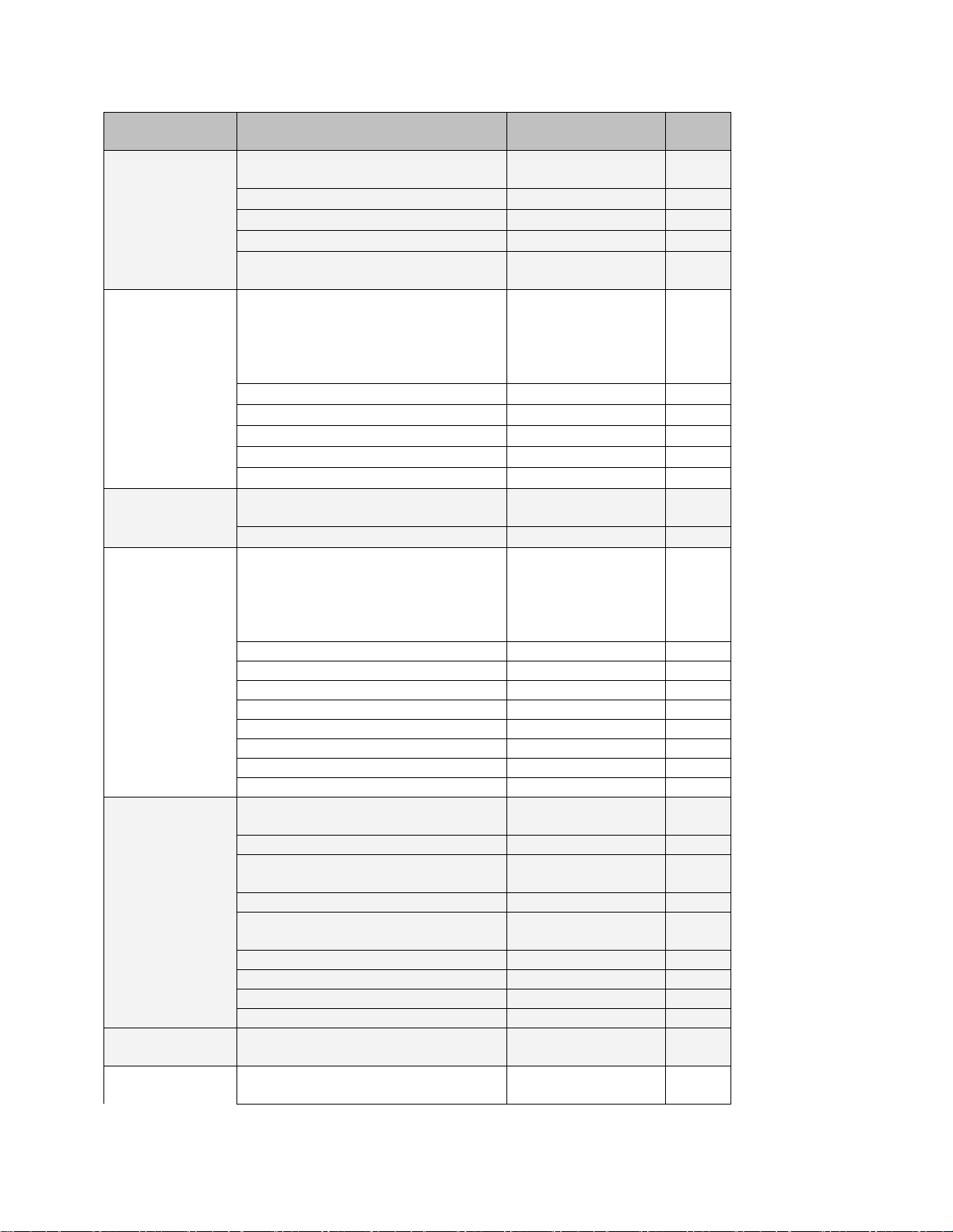
Function
Description
Drawing
Page
Chassis
Circuit Board Locator and basic
interconnections
Top view
(not to scale)
6-37
Base Board
Glue logic; supports CPU board
and RS-232 daughterboard.
Parts Locator
6-38
General Dissatisfaction with Subjective Sound Quality .................................................. 5-7
BS.1770 Safety Limiter produces too much gain reduction ........................................... 5-8
Security Passcode Lost (When Unit is Locked Out) ......................................................... 5-8
Connection Issues between the 8700i and a PC, Modem, or Network................ 5-8
Troubleshooting Connections ................................................................................ 5-8
You Cannot Access the Internet After Making a Direct or Modem Connection to
the 8700i: ................................................................................................................. 5-9
TROUBLESHOOTING IC OPAMPS ....................................................................................... 5-10
TECHNICAL SUPPORT ...................................................................................................... 5-10
FACTORY SERVICE .......................................................................................................... 5-10
SHIPPING INSTRUCTIONS .................................................................................................. 5-11
Section 6 Technical Data
......................................................................................................................................... 6-1
SPECIFICATIONS ................................................................................................................ 6-1
Performance............................................................................................................. 6-1
Installation ............................................................................................................... 6-2
CIRCUIT DESCRIPTION ....................................................................................................... 6-7
Overview .................................................................................................................. 6-7
Control Circuits ........................................................................................................ 6-8
User Control Interface and LCD Display Circuits ................................................... 6-8
Input Circuits ............................................................................................................ 6-9
Output Circuits....................................................................................................... 6-10
DSP Circuit .............................................................................................................. 6-13
Power Supply ......................................................................................................... 6-13
Audio-Over-IP Module .......................................................................................... 6-14
Streaming Server ................................................................................................... 6-14
ABBREVIATIONS ............................................................................................................. 6-14
PARTS LIST .................................................................................................................... 6-16
Obtaining Spare Parts ........................................................................................... 6-16
Base Board ............................................................................................................. 6-17
CPU board .............................................................................................................. 6-19
RS-232 Board .......................................................................................................... 6-20
Input/Output (I/O) Board ...................................................................................... 6-21
Auxiliary Input/Output Board ............................................................................... 6-24
DSP Board ............................................................................................................... 6-28
Interface Board ...................................................................................................... 6-30
Headphone Board ................................................................................................. 6-31
Encoder Board ....................................................................................................... 6-32
LCD Carrier Board .................................................................................................. 6-32
Power Supply Distribution Board ......................................................................... 6-32
SCHEMATICS AND PARTS LOCATOR DRAWINGS .................................................................. 6-34
Function
Description
Drawing
Page
Contains:
Drawing
System Connections
Schematic 1 of 4
6-39
CPU board interface
Schematic 2 of 4
6-40
Power Supply Monitor
Schematic 3 of 4
6-41
CPLD, General Purpose Interface,
and Remotes
Schematic 4 of 4
6-42
CPU board
Control microprocessor. Services
front panel, serial port, Ethernet,
DSP board, and control board. Resides on base board.
Contains:
Parts Locator
Drawing
6-43
Ethernet
Schematic 1 of 5
6-44
General Purpose Bus
Schematic 2 of 5
6-45
Memory
Schematic 3 of 5
6-46
Miscellaneous Functions
Schematic 4 of 5
6-47
Power and Ground Distribution
Schematic 5 of 5
6-48
RS-232 Board
Supports Serial Port
Parts Locator
Drawing
6-49
Schematic 1 of 1
6-50
Main I/O Board
Analog Input/output
AES3 Input/output
Composite Output
SCA Input.
Contains:
Parts Locator
Drawing
6-51
Interconnects
Schematic 1 of 8
6-52 L and R Analog Inputs
Schematic 2 of 8
6-53 L and R Analog Outputs
Schematic 3 of 8
6-54 Composite / SCA
Schematic 4 of 8
6-55 Digital I/O
Schematic 5 of 8
6-56 Interface and Power Distribution
Schematic 6 of 8
6-57 Control and Miscellaneous 1
Schematic 7 of 8
6-58 Control and Miscellaneous 2
Schematic 8 of 8
6-59
DSP Board
DSP Chips; Local +3.3V regulator.
Contains:
Parts Locator
Drawing
6-60
Interconnects
Schematic 1 of 9
6-61
Enhanced Serial Audio
Interface (ESAI)
Schematic 2 of 9
6-62
Control Interface
Schematic 3 of 9
6-63
External Memory Controller
Interface 1
Schematic 4 of 9
6-64
Power and Ground
Schematic 5 of 9
6-65 86xx 8-Bit Control Interface
Schematic 6 of 9
6-66 Clock Generation and CPLD
Schematic 7 of 9
6-67 Power Distribution
Schematic 8 of 9
6-68
External Memory Controller
Interface 2
Schematic 9 of 9
6-69
Front-Panel
Boards
LCD Carrier
Contains:
Parts Locator
Drawing
6-70
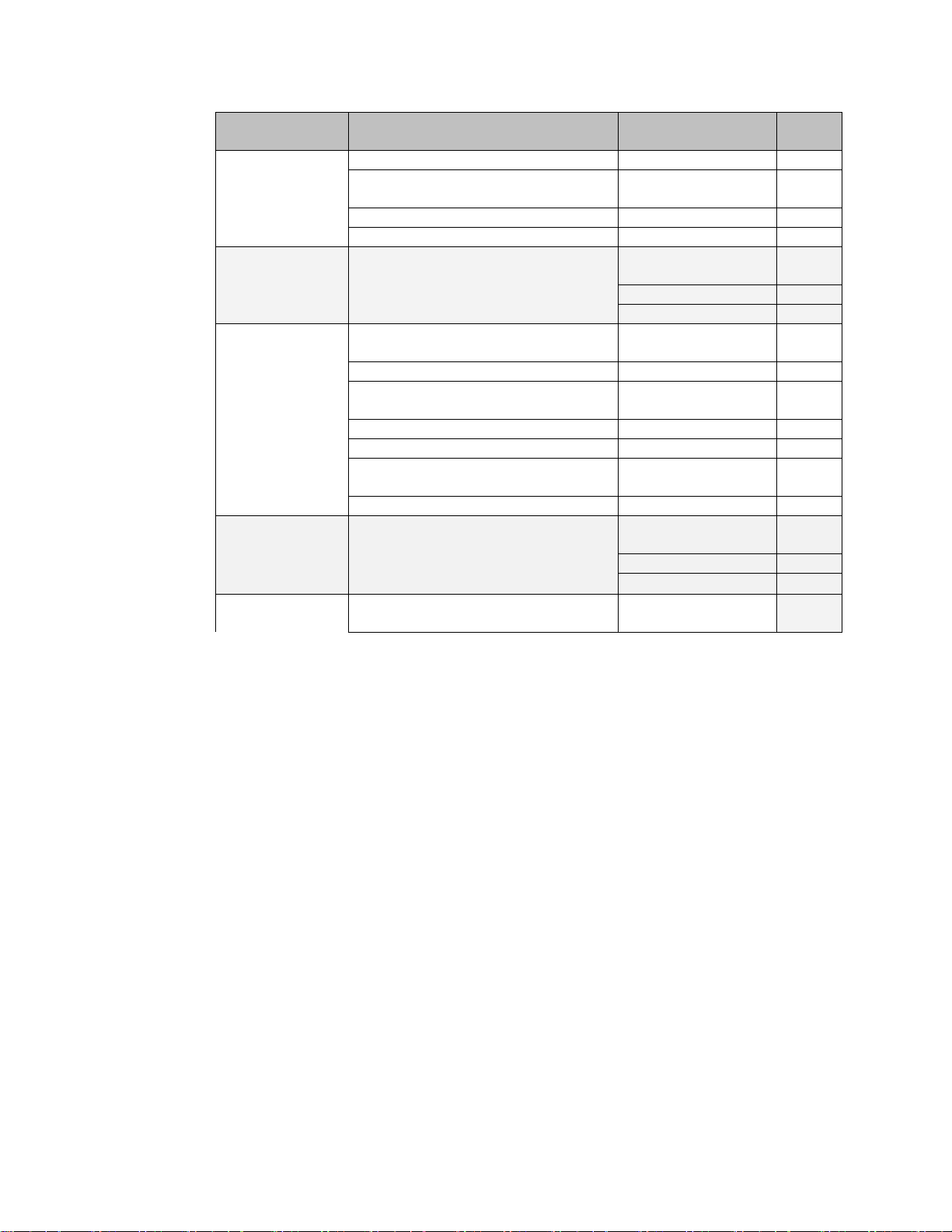
Function
Description
Drawing
Page
LCD Carrier
Schematic 1 of 3
6-71
Headphone and Encoder Board
Parts Locator
Drawings
6-72
Headphone Board
Schematic 2 of 3
6-73 Encoder Board
Schematic 3 of 3
6-74
Front-Panel In-
terface
Front Panel Interface Board
Parts Locator
Drawing
6-75
Board
Schematic 1 of 2
6-76
Schematic 2 of 2
6-77
Aux I/O Board
Aux !/O Board
Contains:
Parts Locator
Drawing
6-78
Interconnects
Schematic 1 of 6
6-79
SCA Inputs, Sync &
Digital Composite
Schematic 2 of 6
6-80
Dante SRC & CPLD
Schematic 3 of 6
6-81
Dante Codec & Network Interface
Schematic 4 of 6
6-82
Streaming SRC &
Raspberry Pi Interface
Schematic 5 of 6
6-83
Streaming Network Interface
Schematic 6 of 6
6-84
Power
Adapter
Power Distribution Board
Parts Locator
Drawing
6-85
Schematic 1 of 2
6-86
Schematic 2 of 2
6-87
DSP Block
Diagram
Audio processing block diagram
Drawing 1 of 1
6-88

Index
1
10 MHz reference 2- · 11
19 K Ref control 2- · 11
2
2B Drive 3- · 57
2B Release 3- · 57
8
8100A/ST 1- · 19
8100A1 1- · 19
8100AST 1- · 19
8100AXT2 1- · 19
8200ST 2- · 15
8400
importing presets from 3- · 95
8700i OPTIMOD-FM 1- · 1
A
A/D converter
Circuit description 5- · 10
Abbreviations
Table of 6- · 14
AC Line Cord Standard 2- · 2
Administrative Operations
via terminal program 2- · 50
Adobe pdf 1- · 1
Advanced Modify 3- · 18
AES/EBU I/O 2- · 8
AES3 I/O 2- · 5
AES67 2- · 100
AGC
controls 3- · 39
defeating 3- · 25
Defeating 3- · 40
external AGC setup 2- · 15
meter 2- · 14
meter 3- · 2
AGC 3- · 9
AGC Drive 3- · 40
AGC Matrix 3- · 43
AGC Release
Master 3- · 41
Analog
output 2- · 7
Analog auto-fallback 2- · 40
Analog baseband outputs 1- · 10
analog composite output 2- · 5
Analog delay
remote control 2- · 62
analog fallback 2- · 32
Analog I/O 1- · 10
analog I/O 2- · 5
analog input
fallback 2- · 40
fallback to digital 2- · 40
Analog input
Circuit description 6- · 9
Analog input 2- · 6
Analog input clip level 2- · 27
Analog input ref level
I/O setup 2- · 30
Analog landline 1- · 19
Analog output
Circuit description 6- · 11
Analog output trim 4- · 9
API
adjusting delay time 2- · 54
delay on/off 2- · 53, 55
Archiving presets 3- · 94
Attack
2-Band Bass 2- · 60
2-Band Master · 60
AGC Bass 3- · 44
AGC Master 3- · 44
Multiband 3- · 70
Audio
Connections 2- · 6
Input 2- · 6
Output 2- · 7, 8
audio monitor
streaming 2- · 103
Audio-Over-IP 2- · 100
audio-over-IP 6- · 14
automated control
via PuTTY/Plink 2- · 60
automation
capabilities 2- · 43
Automation

Clock-based 2- · 42
PC Remote 3- · 96
B
B4>B5 coupling 3- · 11
Backing up presets 3- · 94
Balance adjust
I/O setup 2- · 31
balanced
output transformer 2- · 7
Balanced
inputs 2- · 7
Band Mix
Multiband 3- · 68
Band mix controls 3- · 70
Bandwidth
Setting HD 3- · 78
Base board
Reinstalling 4- · 5
removing 4- · 5
baseband spectrum 5- · 4
Baseband spectrum diagram 3- · 47
Basic Modify 3- · 17
Bass
equalizer 3- · 90
Getting sound you want 3- · 88
Bass CLip Mode 3- · 48, 52, 54
Bass Clip Threshold 3- · 50
Bass Coupling
2-Band 3- · 59
AGC 3- · 42
Bass Threshold 3- · 43
Battery
Replacing 6- · 8
Block diagram 6- · 88
brightness
controlling excessive 3- · 75
controlling in HD 3- · 16
Brilliance control 3- · 34
BS.1770
analog radio 1- · 25
GR meter 2- · 15
BS.1770 1- · 24
BS.1770 Limiter
too much GR 5- · 8
BS.1770 Loudness Control Threshold 3- ·
81
BS.1770 loudness meter
limitations 2- · 41
BS.1770 safety limiter
and FInal Limit Drive 2- · 41
setup 2- · 32
BS.1770 Safety Limiter
control functionality 3- · 81
BS.1770 Safety Limiter 2- · 15
Button bar
FM > HD coupling 3- · 74
Buttons · 1
Enter 2- · 13
Escape 2- · 13
Escape 3- · 1
Buzz 5- · 1
bypass
PC remote 1- · 30
Bypass
Locally 1- · 29
Remote interface 1- · 29
test mode 1- · 26
Bypass mode
activate via GPI 2- · 61
C
cable
shielding 2- · 12
Cable 2- · 6
capacitance
separation vs. load 2- · 10
CD mastering
and processing 3- · 6
chassis
ground 2- · 12
Chassis
getting inside 4 · 2
Chassis ground 2- · 12
Circuit description
Control 6- · 8
LCD display 6- · 8
user Control interface 6- · 8
Circuit description 6- · 7
Circuit ground 2- · 12
Classical music 3- · 25, 55
Cleaning front panel 4- · 1
Clip level
I/O setup 2- · 27
Clipper
Controls 3- · 45
Clipper, bass 3- · 11
Clipping
2-Band 3- · 61

Defined 3- · 4
Multiband 3- · 67
Clock
Battery 6- · 8
GPI control of 2- · 62
Setting 2- · 42
Setting via Internet 2- · 69
Clock-based automation 2- · 42
codec artifacts
minimizing 3- · 15
common-mode rejection 2- · 12
Components
Obtaining 6- · 16
composite
digital setup 2- · 38
Composite
Circuit description 6- · 12
isolation transformer 2- · 10
limiter 3- · 13
Composite baseband microwave STL 1- ·
18
composite isolation transformer 1- · 15,
12, 1
Composite level output 1- · 24
Composite Limit Drive 3- · 46
Composite limiter
Pilot tone protection 2- · 10
Composite metering 1- · 24
composite output
analog 2- · 5
digital 1- · 11
digital 2- · 6, 11
Composite output
I/O setup 2- · 37
Level adjustment range 2- · 9
Meter 2- · 14
Setting output impedance 2- · 9
Specifications 6- · 4
Termination 2- · 9
Composite output 2- · 9
Composite outputs 1- · 10
Compression
Defined 3- · 3
Compression Ratio
AGC 3- · 43
Compressor look-ahead
and bass clipper mode 3- · 49
Computer
Connecting to 2- · 4
Troubleshooting connections 5- · 8
Computer interface
Ethernet port 2- · 5
RS-232 2- · 5
serial 1 2- · 5
Computer interface 1- · 12
Connection to PC
Troubleshooting 5- · 8
Connectors
Audio 2- · 6
Connectors 2- · 6
control
scripted 2- · 60
control coupling
FM and HD 3- · 81
Control coupling
FM > HD 3- · 74
Control knob 2- · 14
Control knob 3- · 1
Control setting
Modifying from PC Remote 3- · 93
controls
HD audio 3- · 81
Speech Detect 3- · 12
subharmonic synthesizer 3- · 36
Corrosion 4- · 1
Coupling Control 3- · 68
Cover
Removing 4- · 2
CPU board
Reinstalling 4- · 5
removing 4- · 4
Crossfade 3- · 79
Crossover
2-Band 3- · 60
AGC 3- · 44
Band 1 / Band 2 3- · 72
D
D/A converter
Circuit description 6- · 11
Dante 2- · 5, 100
Dante 6- · 14
de-emphasis
applying to output meter 2- · 37
De-Essing
in HD channel 3- · 83
Defaults
Resetting to 2- · 47
Defeating final clipper 2- · 39
delay
on/off from API 2- · 53, 55

Delay
Analog vs. HD 3- · 76
diversity on/off 3- · 77
diversity vernier 3- · 77
Input/Ouput 3- · 17
delay time
adjusting via API 2- · 54
diagnostic info
fetching via API 2- · 56, 57
Dialnorm
re Loudness Level meter 1- · 25
digital composite
setup 2- · 38
digital composite 2- · 11
digital composite output 2- · 6
digital encoder
setup 2- · 38
digital fallback 2- · 40, 103
Digital I/O 1- · 10
digital input
fallback to analog 2- · 40
invalid or missing 2- · 32
Digital input
Circuit description 6- · 10
Digital links 1- · 16
Digital output
Circuit description 6- · 12
digital radio processing 3- · 15, 74
Display
Removing 4- · 4
Display Interface
Reinstalling 4- · 5
Removing 4- · 4
Distortion
Aliasing 3- · 14
Excessive 5- · 7
in processing 3- · 4
Testing 4- · 10
Troubleshooting 5- · 2
dither
setting 2- · 35
Dither control
HD 3- · 80
diversity delay
on/off from API 2- · 55
Diversity delay
composite on/off 3- · 77
control via GPI 2- · 62
diversity delay 3- · 77
DJ Bass control 3- · 35
Drive control
Multiband 3- · 63
DSP
Block diagram 6- · 88
Circuit description 6- · 13
DSP board
Reinstalling 4- · 5
Removing 4- · 2
Dual microwave STLs 1- · 18
Dull sound
troubleshooting 5- · 5
E
EAS
modulation Low 5- · 6
EAS test tones 1- · 29
Easy setup 2- · 18
EBU R 128 1 · 24
Enter button 2- · 13
Enter button 3- · 1
EQ Frequency control
HD 3- · 82
equalizer
bass shelf 3- · 31
Equalizer
Bass Gain 3- · 31
Bass Shelf Hinge Frequency 3- · 31
Bass Slope 3- · 31
Controls 3- · 31
Parametric Frequency 3- · 32
Parametric Gain 3- · 32
Parametric Width 3- · 32
Equalizer 3- · 10
Error indications
power light flashes 4- · 8
Escape button 2- · 13
Escape button 3- · 1
esses
excessive HD 5- · 6
Ethernet 2- · 68, 92
Ethernet port 2- · 5
Exciter overshoot 1- · 20
Expander
Multiband Downward 3- · 67
F
Factory defaults
Resetting to 2- · 47
Restoring via Terminal Program 2- · 50

Factory preset
Selecting 2- · 23
Factory presets
Table of 3- · 23
Factory presets 1- · 8
Factory service 5- · 10
Field audit of performance 4- · 6
Filter
Pilot Protection 3- · 46
Final Clip Drive 3- · 51
Final clipper
Defeating 2- · 39
Firewall 2- · 64, 68, 92
Firmware
updating 8700i 2- · 72
firmware update
streaming server 2- · 106
Five-band structure
Customizing settings 3- · 62
Setup controls 3- · 62
Five-band structure 3- · 21, 61
FM > HD mode 3- · 74
FM polarity
changing via API 2- · 55
control via GPI 2- · 62
FM Polarity control 2- · 37
FMHD control coupling 3- · 81
Forgotten passcode 2- · 47
Format control
HD 3- · 81
Frequency response
Testing 4- · 9
Front panel
Reinstalling 4- · 6
removing 4- · 3
Unlocking 2- · 46
Front Panel
Cannot access 2- · 47
fuse 6- · 13
G
Gain Reduction
Maximum Delta 3- · 72
Gain reduction metering 3- · 19
Gate indicators 2- · 14
Gate indicators 3- · 2
Gate Threshold
2-Band 3- · 59
AGC 3- · 41
Multiband 3- · 66
Gateway
Setting via terminal program 2- · 52
Gateway 2- · 64, 68, 92
GPI
programming 2- · 61
ground loop
eliminating in composite 1- · 15, 12, 1
Grounding
loss of 4- · 1
Grounding 2- · 12
Grouping 8700is
In PC Remote 3- · 97
H
Half-cosine interpolation limiter 3- · 14
Hard Clip Shape 3- · 52
hardwire bypass 1- · 5
hardwire bypass 2- · 6, 56
HD
Bandwidth 3- · 78
Dither control 3- · 80
EQ frequency control 3- · 82
EQ Gain control 3- · 82
Format control 3- · 81
Frequency response not 20 kHz 5- · 7
GR meter 3- · 3
HF Shelf EQ 3- · 77
Limiter Drive control 3- · 82
Out Level control 3- · 79
Output Sample Rate 3- · 79
Output too bright 5- · 6
Sync control 3- · 80
HD audio controls 3- · 81
HD De-ess 3- · 83
HD delay
setting 3- · 79
HD loudness
adjusting 5- · 6
HD loudness too low 5- · 7
HD Radio
cannot adjust loudness 5- · 7
crossfade 3- · 79
loudness mismatch between FM and HD 5- ·
7
match loudness of HD and FM 3- · 82
HD/FM loudness
dips during crossfades 5- · 7
does not match 5- · 6
Headphone

Jack 2- · 13
Jack 3- · 1
Level control 2- · 13
Level control 3- · 1
Headphone amplifier
Reassembling 4- · 6
Removing 4- · 3
Headphones
low-delay monitoring 1- · 28
low-delay monitoring 2- · 38
Headphones 1- · 26
HF Clipping 3- · 51
HF Enhance control 3- · 35
HF enhancer 3- · 10
hiding meters 2 - · 45
High frequency limiter 3- · 11
High Frequency Limiter 3- · 72
Highpass Filter 3- · 35
Hum 5- · 1
hyperlinks 1- · 1
Hyperterminal 2- · 48
I/O setup 2- · 27
Inspection of contents 2- · 1
Instrumental format 3- · 28
Interface type
Changing via terminal program 2- · 53
Intermediate Modify 3- · 18
Internet
Cannot access 5- · 9
Time server 2- · 69
IP address
changing via Terminal Program 2- · 51
Entering into 8700i 2- · 64
serial connection 2- · 58
streaming server 2- · 105
terminal connection 2- · 58
ITU-412 3- · 83
ITU-R 412 3- · 15
ITU-R 412 requirements 2- · 24
ITU-R BS.1770 1- · 24
J
I
I/O
AES/EBU 2- · 8
Connections 2- · 3
I/O assembly
Removing 4- · 2
I/O board
Reinstalling 4- · 5
IC opamps
Troubleshooting 5- · 10
Icecast 2- · 106
Icecast2 2- · 103
Idle Gain 3- · 43
In meters 2- · 14
In meters 3- · 2
Independent mode 3- · 74
Input
Analog 2- · 6
SCA, Specifications 6- · 5
Subcarrier 2- · 9
Input conditioning 3- · 7
Input level
Line-up 1- · 21
Input level meters 1- · 23
Input Select
Control via GPI 2- · 61
Input selector
J.17
and NICAM 1- · 17
preemphasis applied to digital audio output
6- · 4
Jazz format 3- · 28
Jensen transformer 1- · 15, 12, 1
Joystick 2- · 13
Joystick 3- · 1
K
Keyboard shortcuts 3- · 97
L
Latency
Low delay presets 3- · 25
Ultra-low-delay presets 3- · 22
LCD display
Reassembling 4- · 6
LCD display 6- · 9
Less-More control
Grayed-out 3- · 19
Less-More control 3- · 17
Level
Metering 1- · 23
Transmission 1- · 23

Limit Threshold
Multiband 3- · 54, 71
Limiter
Multiband Attack 3- · 72
Limiting
Defined 3- · 3
Line voltage 2- · 2
Line-up tones
System will not pass at 100% modulation 5- ·
5
Line-up tones 1- · 25
LLHard mode 3- · 49
Local mode
streaming server 2- · 105
locate joystick 2- · 13
Locate joystick 3- · 1
Location 1- · 13
Lock
Driven equipment cannot lock to 8700i
output 5- · 6
Locked out 2- · 47
Lockout
Front panel 2- · 46
Lookahead
Multiband Control 3- · 73
Look-ahead
Compressor/limiter 3- · 11
Lookahead 3- · 60
look-ahead limiter 3- · 16, 75
Look-ahead limiting
Defined 3- · 4
Lossy data reduction
In studio 1- · 20
NICAM 1- · 17
Used in STLs · 16
Loudness
adjusting HD/FM 5- · 6
Insufficient 5- · 7
Insufficient due to ITU412 controller 5- · 1
Insufficient due to poor peak control 5- · 1
match HD and FM channels 3- · 79, 82
Loudness and distortion 3- · 4
loudness control
in digital radio 2- · 32
loudness GR meter 2- · 15
loudness meter 1- · 24
Loudness Safety Limiter
setup 2- · 32
low-delay monitor 3- · 45
low-delay monitor processor 1- · 4, 28
L–R will not null 5- · 6
M
Main board
Reinstalling 4 · 5
Matrix
AGC 3- · 43
Max Delta GR
AGC 3- · 42
Max Distortion Control 3- · 71
MB Drive control 3- · 63
MB GR Meter switch 3- · 2
meter
output · 37
loudness 1- · 24
MPX Power 3- · 84
MPX Power Level 3- · 84
Meter Sel control 3- · 77
Meters
circuit description 6- · 9
studio 1- · 21
Mod reduction
explained 2- · 22
via GPI 2- · 62
Modem
Preparing for connection 2- · 85
Setting up 2- · 65
Specification for 2- · 67
Modem init string
changing from front panel 2- · 65
Changing via terminal program 2- · 53
Modulation control
Troubleshooting poor 5- · 1
Modulation Mode control 2- · 38
monitor
low-delay 3- · 45
Monitor Drive control 3- · 45
Monitor Mute
BPI control 2- · 62
monitor processor 1- · 4
Monitoring
Requirements for 3- · 6
Monitoring 1- · 26
MPX Power Level meter 3- · 84
MPX Power meter 3- · 84
MPX Pwr Ctrlr Gate control 3- · 87
Multiband
gain reduction meters 2- · 14
Gain reduction meters 3- · 2
Multiband Band Mix 3- · 68
Multiband Limit Threshold 3- · 61
Multipath Mitigator

and HD chain 3- · 15
and SSB overshoot 3- · 13
bypassing 2- · 32
Multipath Mitigator 1- · 7, 26
Multipath Mitigator 3- · 8, 36
Multiplex power
Compliance graph 3- · 85
Multiplex power 2- · 15
Multiplex power 3- · 3, 15, 83
Multiplex power offset 3- · 26, 27, 42, 48,
86
Multiplex Power Threshold control 3- · 85
Music Mode
forcing 3- · 73
MX controls
Bass Limiting 3- · 54
Bass PreLimit Mode 3- · 54
Bass PreLimiting 3- · 54
Distortion Control 3- · 54
Multiband Clipping 3- · 54
Peak Limiter Drive 3- · 53
MX structures 1- · 6
N
Netcat
automated control using 2- · 60
automation using 2- · 59
Networking 2- · 63
News format 3- · 29
NICAM 1- · 17
Noise
Troubleshooting 5- · 3
Null modem cable
Communicating through 2- · 74
Null modem cable 2- · 67
O
Out level control
HD 3- · 79
Out meters 2- · 14
output
digital, specifications 6- · 4
Output
Analog 2- · 7
Composite 2- · 9
composite, Specifications 6- · 4
digital, Specifications 6- · 3
Output configuration 2- · 21
Output level
I/O setup 2- · 33
Output levels
Quick setup 2- · 22
Output meters 1- · 23
overshoot
reduction 1- · 20
Overshoot
In exciter 1- · 20
Overshoot
Excessive 5- · 1
Overshoot 3- · 86
Overshoot Compensation Drive 3- · 51
P
Parametric equalizer 3- · 10, 31
Parts
Obtaining 6- · 16
Parts list
Aux I/O board 6- · 24
Base board 6- · 17
CPU board 6- · 19
DSP board 6- · 28
Encoder board 6- · 32
Headphone board 6- · 31
I/O board 6- · 21
Interface board 6- · 30
LCD carrier board 6- · 32
Power supply 6- · 32
RS-232 board 6- · 20
Parts list 6- · 16
Passcode
default ADMIN 2- · 46
Forgotten 2- · 47
Programming 2- · 44
PC
Orban installer program 2- · 68
PC control
security 1- · 30
PC hardware requirements 2- · 67
PC Remote
aliases 3- · 97
Modifying control setting 3- · 93
moving alias folders 3- · 99
Multiple coexisting versions 3- · 98
Operating from keyboard 3- · 97
Recalling preset 3- · 93
Saving Preset 3- · 94
Setting up new connection 3- · 92
Upgrading versions 3- · 98

PC Remote Software 3- · 91
Peak control criteria 1- · 13
peak limiter
8500-style 3- · 50
MX controls 3- · 53
Phase
HD 3- · 79
Phase Correct Crossover 3- · 8
Phase Corrector
bypassing 2- · 32
Phase Corrector 3- · 8, 36
Phase Rotator 3- · 35
phase skew corrector 1- · 7, 26
phase skew corrector 3- · 8
Phase-linear
System group delay spec · 13
Pilot Protection Filter 3- · 46
pilot reference 2- · 40
pilot reference 6- · 5
pilot reference control 2- · 11
Pilot tone
Frequency out of tolerance 5- · 6
Reference output 2- · 10
Plink
automation using 2- · 59
Plink 2- · 59
polarity
FM analog processing 2- · 55
setting FM 2- · 37
Polarity
HD 3- · 79
Pop-up menu 2- · 14, 1
Port
Terminal 2- · 57
Port #
Setting via terminal program 2- · 52
port number
setting 2- · 58
Ports 2- · 68, 92
Power
Cord 2- · 5
Ground 2- · 12
power light
flashing 4- · 8
power supply
Orban part # 6- · 13
Power supply
Circuit description 6- · 13, 14
Parts list 6- · 32
pre-emphasis
setting 2- · 27
Pre-emphasis
in STLs 1- · 13
Quick setup 2- · 19
Side-effect of changing 3- · 19
preset
recalling 2- · 41
Preset
8400 compatibility 3- · 95
Backup 3- · 94
Deleting user 3- · 20
recall via GPI 2- · 61
Recalling via terminal program 2- · 53
restoring archived 3- · 95
Saving from PC Remote 3- · 94
sharing between 8700is 3- · 96
Presets
Factory 1- · 8
factory 3- · 24
Gregg 3- · 27
Impact 3- · 28
Instrumental 3- · 28
Jazz 3- · 28
Loud 3- · 28
News-Talk 3- · 29
Rock 3- · 29
Saving user 3- · 19
Sports 3- · 29
Table of factory 3- · 23
UL (Ultra-Low Latency) 3- · 22, 6
Urban 3- · 30
User presets 1- · 9
processing
for HD Radio 3- · 15
Processing
AGC 3- · 9
block diagram 6- · 88
Customizing 3- · 17
Equalization 3- · 10
Input conditioning 3- · 7
Intelligent clipping 3- · 11
Multiband compression 3- · 11
Stereo enhancement 3- · 8
Tutorial 3- · 3
Two-band purist 3- · 15
processing structures 1- · 6
Processing structures discussed 3- · 21
Protection preset 3- · 25
Purist processing 3- · 15
PuTTY
direct control using 2- · 59
PuTTY 2- · 59

Q
Quick setup 2- · 18
Quiet on-air levels 5- · 1
R
Rack-mounting unit 2- · 3
Raspberry Pi 6- · 14
ratings encoder 2- · 8, 36
Ratio
Control 3- · 9
RDS
terminal timeout 2- · 96
timeout 2- · 94
RDS -2 · 89
Rear panel 2- · 5
Recalling preset
via terminal program 2- · 53
reference input
wordclock 1- · 12
Registration card 2- · 1
relay bypass 1- · 5
relay bypass 2- · 6, 56
Release
AGC Bass 3- · 44
Multiband 3- · 64
Multiband Delta 3- · 72
Remote
PC Remote software 3- · 91
Remote control
Bypass 1- · 29
Connecting 2- · 3
Remote control 2- · 5
Remote control interface
Connecting 2- · 3
programming 2- · 61
Remote control interface 1- · 12
Remote interface 2- · 12
Remote interface connector 2- · 5
Remote Software 2- · 5, 58, 66, 71, 72
Resetting 8700i 2- · 47
Restoring archived presets 3- · 95
RFI 5- · 1
Right channel balance
I/O setup 2- · 31
Rock format 3- · 29
Rotary encoder
Removing 4- · 3
Rotary Encoder
Reassembling 4- · 6
Routine maintenance 4- · 1
RS232 board
Reinstalling 4- · 5
RS-232 connector 2- · 5
RS-232 interface
Circuit description 6- · 9
removing board 4- · 4
Rumble Filter 3- · 35
S
Sample Rate control
HD 3- · 79
sample rate conversion
overshoot in 1- · 3
Sample rate converter
Testing 4- · 11
Saving user presets 3- · 19
SCA
digitized setup 2- · 38
Input, specifications 6- · 5
inputs 1- · 11
Interference from stereo 5- · 4
SCA input
digitized 2- · 11
SCA inputs
analog 2- · 5
Schematics
Table of contents 6- · 34
Screen display 2- · 14
Screen display 3- · 2
Screens
System Setup 2- · 18
scripted control 2- · 60
security
view meters 2- · 45
Security
PC Remote 2- · 47
Security 1- · 30
Security 2- · 44
serial 1 connector 2- · 5
serial 2 connector 2- · 5
Serial Communications
Setting up 2- · 74
serial connection
via port #1 2- · 57
via Port #2 2- · 48
Serial connection
Setting up direct 2- · 65

Service 5- · 10
Setup
I/O 2- · 27
Quick 2- · 18
Shelf equalizer 3- · 31
Shelving equalizer
Bass, slope of 3- · 10
Shipping instructions 5- · 11
SHOUTCast 2- · 106
SHOUTcast2 2- · 103
Shrill sound
Troubleshooting 5- · 5
Sibilance
excessive HD 5- · 6
excessive in HD channel 3- · 83
Signal flow diagram 6- · 88
Signal flow in 8700i 3- · 7
Silence sense
Tally output 2- · 63
Silence sense 2- · 40
silence threshold 2- · 40
Single-sideband mode 3- · 12
SNMP 1- · 8
SNMP 2- · 85
Software
updating 8700i 2- · 72
Software Updates 1- · 8
Solo 3- · 69
Source material
Requirements for 3- · 6
Spare parts
Obtaining 6- · 16
Specifications 6- · 1
Speech Bass Clip Threshold 3- · 52
Speech Detect control 3- · 12
Speech Mode
forcing 3- · 73
speech mode 3- · 11
speech/music detector
overriding 3- · 73
Speech/music detector 3- · 49, 73
Sports format 3- · 29
SSB
GPI control 2- · 62
SSB mode 3- · 12
Stereo Coupling
Multiband Downward Expander 3- · 72
Stereo encoder
control via GPI 2- · 61
SSB/VSB Operation 3- · 12
Testing 4- · 11
Stereo encoder 3- · 12
Stereo enhancement 3- · 8
Stereo Enhancer
Amount 3- · 38
Depth 3- · 38
Diffusion 3- · 38
In/Out 3- · 38
Ratio Limit 3- · 38
Style 3- · 38
Stereo/Mono
HD output 3- · 77
STL
low frequency cutoff 1- · 13
systems 1- · 16, 18
streaming server
codec 2- · 105
compatible players 2- · 104
IP address 2 - · 105
setting audio source 2- · 104
setting Mode 2- · 105
updating firmware - · 106
streaming server 2- · 103
streaming server 6- · 14
Studio Level Controller
Installation 2- · 15
Studio Level Controller mode 2- · 19
Studio-transmitter link 1- · 16
Subassembly removal and reinstallation 4-
· 2
Subcarrier
Input, specifications 6- · 5
inputs 2- · 10
Subcarrier input 1- · 11
Subcarrier input 2- · 9
subcarriers
digitized 1- · 11
digtized 5- · 7
subharmonic synthesizer 3- · 10, 36
Subnet
Crossing 2- · 64
Mask 2- · 64
Subnet Mask
Setting via Terminal Program 2- · 51
Sync control
HD 3- · 80
sync reference
10 Mhz 1- · 12
wordwordclock 1- · 12
sync reference 2- · 11
System clock
Setting 2- · 42

System setup
Quick setup 2- · 18
System Setup screen 2- · 18
T
Talk format 3- · 29
Tally output
Programming 2- · 63
Silence sense threshold 2- · 40
Wiring 2- · 4
Technical support 5- · 31, 10
Telephone support 5- · 31, 10
Telnet 2- · 57, 92
terminal connection
timeout 2- · 57
terminal connection 2- · 48
Terminal Port 2- · 57
Terminal Port #
Changing via terminal program 2- · 52
terminal timeout
RDS 2- · 96
Test modes 3- · 88
Threshold
2-Band Bass Compressor 3- · 60
2-Band Master Compressor 3- · 60
Band-5 Clip 3- · 71
Bass Delta 3- · 44
Master Delta 3- · 44
Multiband Compression 3- · 70
Multiband Speech 3- · 61, 73
Time & date 2- · 19
Time Server 2- · 69
timeout
RDS connection 2- · 94
terminal connection 2- · 57
Tone
activate via GPI 2- · 61
Transformer
Composite isolation 2- · 10
Troubleshooting
Installation 5- · 1
true peak control 1- · 3
Two-band structure
Customizing settings 3- · 57
Setup controls 3- · 57
Two-band structure 3- · 21, 55
U
Ultra-low Latency
and clipping distortion controller 3- · 11
and compressor look-ahead 3- · 11
Ultra-low-latency presets 3- · 21, 22
Unlocking 8500
via Terminal Program 2- · 50
Unlocking 8700i 2- · 47
Unlocking unit 2- · 46
Unpacking 2- · 1
Updating software 2- · 72
Urban format 3- · 30
User preset
deleting 3- · 20
User presets
Archiving 3- · 20
Creating 3- · 17, 19
User presets 1- · 9
V
Vestigial sideband 3- · 12
view meters 2- · 45
Voice/music balance 3- · 19
VPN 2- · 64
VPN, setting up 2- · 68, 92
W
Warranty 1- · 30
Warranty 6- · 7
Whistle on-air
Troubleshooting 5- · 4
Window Release 3- · 43
Window Size 3- · 42
Windows
Installing services 2- · 66
word length
setting 2- · 35
Word Length control
HD 3- · 80
wordclock 1- · 12
wordclock 2- · 11
X
Xponential Loudness

and HD processing 3- · 15
controls 3- · 38
description of 3- · 10
Xponential Loudness 1- · 6

 Loading...